 Ping Wang
 Shuya Xu
 Shengjun Shao1*
95% of researchers rate our articles as excellent or good
Learn more about the work of our research integrity team to safeguard the quality of each article we publish.
Find out more
ORIGINAL RESEARCH article
Front. Earth Sci. , 21 January 2022
Sec. Geohazards and Georisks
Volume 9 - 2021 | https://doi.org/10.3389/feart.2021.762508
This article is part of the Research Topic Multidisciplinary Loess Geohazard Investigations View all 23 articles
The meso-structure of the soil has an important restriction on its engineering properties. Based on dynamic triaxial tests and SEM meso-structure test experiments, this study investigated the meso-scale structural deformation characteristics of Q3 loess samples treated by physical, chemical, and compound improvement methods, before and after strong earthquakes of typical seismic subsidence loess. On this basis, the seismic subsidence performance of the improved method is given under the conditions of frequent earthquakes, fortifying earthquakes, and rare earthquakes. The results show that 1) the physical improvement method has the most obvious effect on the elimination of macropores and overhead pore structures; 2) the chemical method can generate unique glass beads or flocculated fine structures, which can greatly enhance the strength of the soil and play the role of filling, cementing, or buffering, respectively, in the event of a strong earthquake; 3) for several improved treatment methods, the amount of seismic subsidence increases non-linearly with the increase in peak acceleration; and 4) in the event of frequent earthquakes, the earthquake subsidence can be eliminated by the method of adding fly ash, and when the fortification earthquake comes, the dynamic composite method can completely eliminate the seismic subsidence of the site. The related results can give reasonable suggestions for the treatment of seismic subsidence of different foundations in the “resilient urban and rural” and key engineering construction and seismic design of China’s loess area.
China’s Loess Plateau and adjacent areas have recorded 395 earthquakes with a magnitude MS ≥ 5 (Xu et al., 2018). The areas with seismic intensity above VII in the loess area account for 54.21% of the total areas, and the risk of strong earthquakes is extremely high (Wang, 2017; Gao et al., 2015). The systematic study of loess engineering properties in China began in the early days of founding of our country. From the early 1950s to the mid-1960s, Chinese researchers began to carry out a large number of indoor and field experimental research on the engineering properties of collapsible loess on the Loess Plateau such as Lanzhou, Xi’an, Taiyuan, and Luoyang (Huang, 1963). From 1966 to 1978, researchers found that the newly accumulated loess has similar characteristic indexes to Q3 loess, but it has high compressibility and low bearing capacity (Shaanxi Comprehensive Survey Institute, 1973). Since 1978, a breakthrough has been made in the microstructure, pore structure, and its influence on the engineering properties of loess (Gao, 1980; Wang and Lin, 1990; Xu and Guo, 2020; Xu et al., 2020). Unfortunately, none of these methods take into account the dynamic stress like earthquake. The unique macroporous and weakly cemented overhead structure of loess makes the area extremely sensitive to earthquakes (Wang, 2003). Seismic investigations have shown that the earthquake subsidence caused by strong earthquakes, disasters such as ground cracks, and landslides have caused serious damage to housing constructions and road and railway subgrades (Zhang, 2016; Wang, 2018). Therefore, for major construction projects in areas that have been judged as seismic subsidence, site selection not only needs to meet the seismic fortification standards but also should fully consider what kind of foundation anti-seismic treatment method is most effective under fortified earthquakes and rare earthquakes. This is the actual problem of the transformation of infrastructure construction to prevention oriented in the new concept of earthquake prevention and disaster reduction. It is also an urgent problem in scientific research.
A large number of loess seismic subsidence studies have produced fruitful results in three aspects: microstructure and mechanism, determination of seismic subsidence, and estimation of seismic subsidence (Garratt-Reed and Bell, 2005; Shi and Qiu, 2011; Ng et al., 2017; Shao et al., 2018; Dal et al., 2012; Romero and Simms, 2008; Lin et al., 2019; Bruchon et al., 2013; Wen and Yan, 2014; Zhu et al., 2019; Jiang et al., 2014; Wang et al., 2019; Wang and Zhang, 1993). The anti-seismic subsidence treatment technology of the relevant loess foundation is based on fully grasping the characteristics of the loess seismic subsidence and the disaster-causing mechanism. Foundation modification (improvement) methods can be broadly classified into physical modification treatment and chemical modification treatment. These methods have been relatively mature and widely used in dealing with general site and collapsible loess foundation seismic subsidence (Teng et al., 2012; Li et al., 2012). However, there are still few research studies on the improvement methods for the seismic settlement of the loess site under the action of earthquakes of different intensities; furthermore, they still lack systematic and quantitative research and evaluation about the effectiveness of different foundation treatment methods for the same loess engineering site (Deng et al., 2012; Wang et al., 2013; Wang et al., 2016).
The view that the seismic subsidence of the loess foundation is mainly controlled by its microscopic structure has been recognized by many scholars. Shi Yucheng et al. and Deng Jin et al. discussed the influence of medium and large pores and particle skewness on loess seismic subsidence and affirmed the feasibility of studying loess structural changes with microstructure (Shi and Li, 2003; Deng et al., 2007); Wang Lanmin et al. and Li Lan et al. obtained quantitative data on the area of overhead pores through electron microscope photos and established the relationship between loess seismic subsidence characteristics and soil constitutive models (Wang et al., 2007; Li et al., 2005). With the development of microstructure analysis theory, such as the introduction of fractal theory, the improvement of CT technology, and image processing technology, a new feasible method for studying loess earthquake disasters from a microscopic perspective has been provided (Gu et al., 2011; Zhu and Chen, 2009; Wei, 2019).
This study uses indoor dynamic triaxial tests, scanning electron microscopy, image processing technology, and numerical simulation to improve the commonly used loess foundation physical improvement method and dynamic compaction method, which can effectively solve the general building foundation deformation and settlement problems. The cement modification method and fly ash modification method are applied to the seismic settlement loess site (fly ash modification method, which can recycle industrial waste, is an environmental protection technology) to reveal the meso-structure characteristics of the foundation treatment methods under strong earthquake loads, get results of statistical analysis of the particle size and pore size distribution of the sample before and after the test with different seismic subsidence treatment techniques, get the correlation with the macroscopic failure characteristics of the sample, and then discuss the effect of seismic subsidence treatment. On this basis, the most scientific and economical treatment method for seismic subsidence loess engineering site is proposed.
The undisturbed area along the Yuzhong County of Lanzhou City on the Baolan Passenger Dedicated Line with strong seismic subsidence is selected. This area is a typical area with thick loess coverage. The thickness of Q3 loess reaches 28m, which can be used as ideal loess seismic settlement study place. The undisturbed samples were obtained through the excavation of artificial exploration wells, and the sampling depth was 4 m. All the soil samples were undisturbed Q3 loess, and their physical properties are shown in Table 1.

TABLE 1. Soil physical property parameter table.
The original sample (YZ-1) is cut into a cylinder of 50 mm × 100 mm (diameter × height). In order to ensure the consistency of its physical parameters, the essential effects of different anti-seismic subsidence improvement methods are analyzed; a sufficient amount of loose soil samples is taken around the same depth of the exploratory shaft wall. There have been previous studies on the optimal addition amount of fly ash and cement (refer to the references). Related experiments will not be repeated here, and the relevant data will be quoted directly. The fly ash content in the fly ash improvement method is 18% (Wang et al., 2013). In the cement–soil improvement method, #425 Portland cement was selected, and the optimal cement content was selected at 5% for the ratio, according to the previous research results (Wang, 2018). Various samples and their physical properties are shown in Table 2. When using chemical methods, prepare a set of fly ash (FMH-1) and cement–soil (SN-1) samples with a density consistent with the natural density of the site soil of 1.39 g/cm3; when using physical improvement methods, according to the compaction requirements of loess foundation in the actual project, a set of dynamic compaction samples (QH-1) are made with a density of 1.75 g/cm3; the compound improvement methods means to prepare one set of dynamic compaction–fly ash (FH-1) and dynamic compaction–cement–soil (FH-2) samples; and the additive content and sample density are consistent with physical and chemical improvement methods, respectively. All the above methods are adopted.
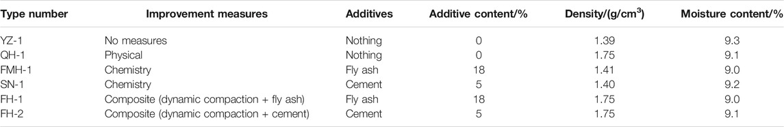
TABLE 2. Physical property parameters of original and modified samples.
The sample of the visual structure test is the soil sample before and after the abovementioned indoor dynamic triaxial test. First, the undisturbed loess, dynamic compaction, fly ash, and cement-modified samples before and after the dynamic triaxial test are 12 groups. After natural drying, they are completely air-dried. The air-dried samples are separated, and the cross sections are obtained and selected. The small soil block that is leveled and has the original fresh surface is used as the observation sample, prepared into a thin slice of 10 mm × 10 mm × 2 mm (length × width × height), and the bottom is leveled.
The test instrument is the WF-12440 dynamic triaxial-torsion shear test system of the Key Laboratory of Loess Earthquake Engineering of China Earthquake Administration (as shown in Figure 1A). The test adopts the consolidated undrained test (CU). The axial stress during consolidation is 200kPa, and the consolidation ratio Kc is 1.69 (Sheng et al., 1999). The microstructure image of the soil sample was acquired using the KYKY2800B electron microscope of the Key Laboratory of Loess Earthquake Engineering, China Earthquake Administration, as shown in Figure 1B. After scanning the soil sample, select images of the same magnification and secondary images with clear particles and pores were used for quantitative analysis, and we used image processing software for normalization and binarization of the secondary images for analysis to get the required parameters (Xu et al., 2017).
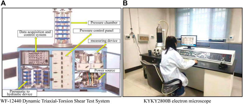
FIGURE 1. Test system. (A) WF-12440 dynamic triaxial-torsion shear test system and (B) KYKY2800B electron microscope.
After the consolidation and deformation are stabilized, dynamic stresses of different amplitudes are applied to 7–10 specimens in the same group, and the relationship curves between dynamic stress
This research focuses on the quantitative analysis of loess grain and pore changes, number, size, shape, cementation form, and fractal characteristics of loess particles before and after the earthquake in different method. The classification refers to 12 types of microstructures that have been widely recognized (Shi and Li, 2003). The skeletal morphology of loess particles seen in the electron microscope can be roughly divided into three types: single-grain, aggregated, and agglomerated. Single particles include clay particles (less than 5 μm), powder particles (5–50 μm), and sand particles (greater than 50 μm). In addition to a small amount of these three particles accumulated in a separate form to form scattered point contacts and mosaic contacts, they are mainly aggregated or the clot shape appears. Aggregate (50–100 μm) is a unit with low strength, which has collapsed and disintegrated. In addition to elastic deformation, it also produces partial plastic deformation. After unloading, the rebound of the clot is constrained by the aggregate to form a residual strain. The clot (30–70 μm) is a unit with higher strength and only undergoes elastic deformation. The pore size is undoubtedly one of the important factors affecting the occurrence of seismic subsidence. Generally, a pore diameter is used as the standard for classification (Gao, 1980; Deng et al., 2007). The classification standard is shown in Table 3.
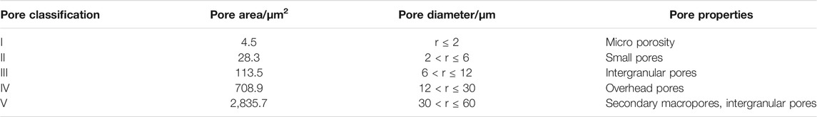
TABLE 3. Classification of loess pore microstructure.
The processing of microstructure images mainly includes image binarization, repair of fractures, removal of noise, automatic/manual identification of particles and pores, and statistics of their quantity and geometric information.
The microstructure images of 12 samples before and after the seismic subsidence test under 400 times magnification were obtained which include undisturbed loess and modified loess sample, and the grain characteristics and pore characteristics of the samples were analyzed.
For general loess samples, except for a small amount of clay, powder, and sand in the form of single particles, soil particles are mainly presented in the form of aggregates. Under 400 times magnification, it can be clearly seen that the microstructure is characterized by a large aggregate particle size, a large number of coarse mineral particles, and point contact between the particles, and an overhead structure is formed between multiple particles, as shown in Figure 2A. After the test, the overhead pore structure of the undisturbed sample is significantly reduced and the average particle size of the aggregates is reduced, but the particle numbers has risen. This is consistent with the collapse of the overhead pore structure obtained earlier, which is an important cause of seismic subsidence. At the same time, it can be seen that the sample in this area is relatively loose so that the microstructure of the sample is still in point contact and there are many large and medium pores in the case of seismic subsidence.
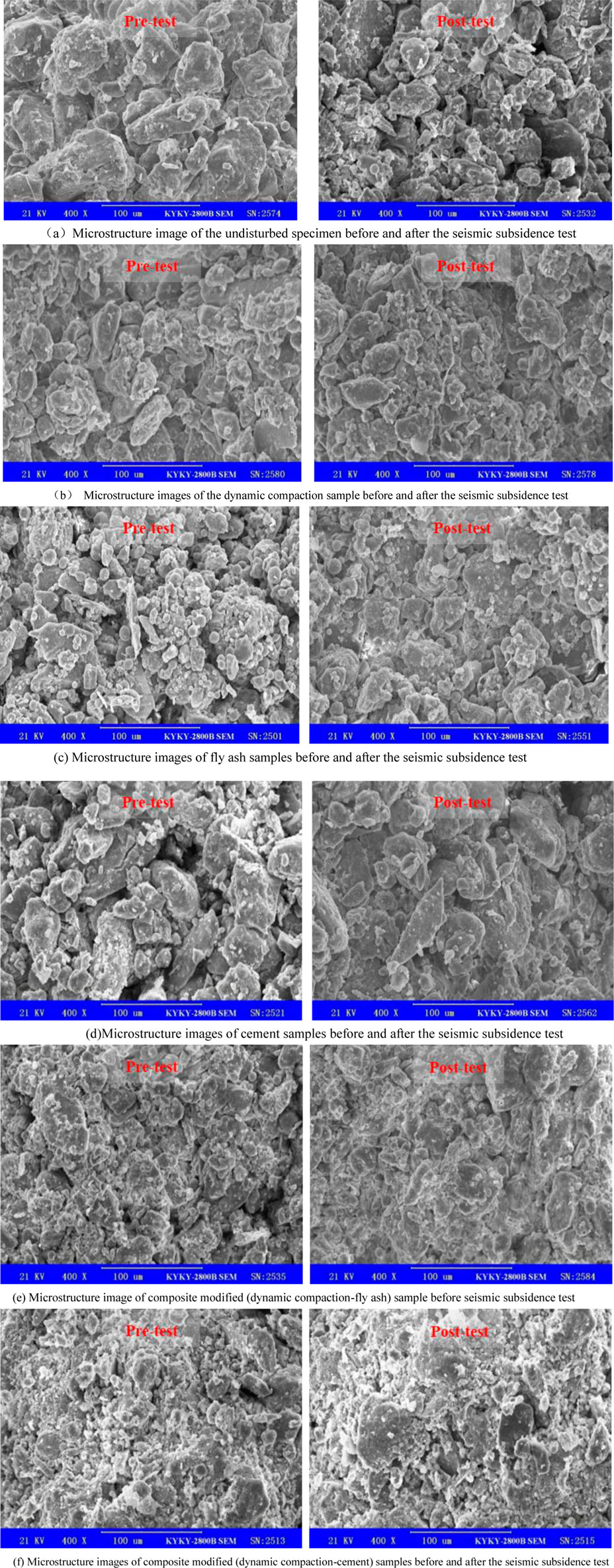
FIGURE 2. Microstructure image of samples before and after the seismic subsidence test. (A) Microstructure image of the undisturbed specimen before and after the seismic subsidence test. (B) Microstructure images of the dynamic compaction sample before and after the seismic subsidence test. (C) Microstructure images of fly ash samples before and after the seismic subsidence test. (D) Microstructure images of cement samples before and after the seismic subsidence test. (E) Microstructure image of composite modified (dynamic compaction–fly ash) sample before seismic subsidence test. (F) Microstructure images of composite modified (dynamic compaction–cement) samples before and after the seismic subsidence test.
The microstructure of the sample before and after the seismic subsidence test after the dynamic compaction is shown in Figure 2B. Before the test, the loess shows obvious flocculent structure. The large aggregates collapsed due to compaction and further broke into small aggregates; the particles were arranged more densely, and they are in the area of contact. After the test, the vibrating effect of the strong earthquake makes the granular mosaic structure of the dynamic compaction sample after the test more obvious than that before the test, that is, the small and medium particles are filled in the middle of the pores, and the contact between the particles is no longer point-like. The contact area is larger but not completely embedded, and the boundary between particles is still relatively obvious, which is convenient for dividing it in statistical analysis.
The microstructure of the modified fly ash sample before and after the test is shown in Figure 2C. Before the test, the sample structure showed that the surface of the soil particles is covered with unique spherical particles, that is, glass beads with a content of more than 70% in the fly ash. These microbeads are mostly on the surface of loess particles or filled in the medium and large pores, which undoubtedly have a compact and homogeneous effect on the soil; on the other hand, the soluble oxides (SiO2 and Al2O3, etc.) in fly ash forms hydrated salts with water and soil hydrates, which increase the strength of intergranular cementation. The glass microbeads formed by fly ash not only increase the small and medium particles but also fill and eliminate some of the overhead and large and medium pores; more importantly, the unique spherical microbeads close to the standard form play a role in adjusting the particle arrangement. As a result, the sample does not undergo shear failure after the triaxial test but manifested itself as swelling in the middle of the sample and microscopically as the peak of the curve caused by the formed particles or glass beads between 20 and 30 um; the reduction of small particle size particles is more obvious.
The microstructure of the sample before and after the test after adding cement is shown in Figure 2D. Before the test, the particle size of the sample does not change much, but the cement obviously changes the form of cementation between the soil particles; the particles are superimposed, and even the cementation becomes for large clots; and the arrangement of particles has also changed to an obvious mosaic structure, and the boundaries between the clots are obvious. For the cement modification method, after the test, as mentioned in the chemical principle, although the strength of the soil is enhanced after the reaction, the brittleness of the soil is also greatly enhanced. The significance of this in actual engineering is that under the condition of the same amount of earthquake subsidence, the foundation with fly ash shows gradual and uniform settlement, while the cement-compacted foundation shows sudden failure. Shear deformation and fracture occur, and this is confirmed by the macroscopic phenomenon of the triaxial test, as shown in Figure 9C; then uneven settlement occurs, which has a great impact on the buildings on it.
The microstructure of the sample before and after the dynamic compaction–fly ash composite improvement test is shown in Figure 2E. In addition to the unique presence of a large number of spherical glass beads, the particle morphology is completely clotted compared with the method of adding fly ash only. The form of intergranular connection is mainly cementation, the arrangement of clots is very dense, and there is no obvious directionality, and the pores are denser after the test.
The microstructure of the sample before and after the dynamic compaction–cement composite improvement test is shown in Figure 2F. Compared with the sample of adding cement only, the particles are more obvious as flocculent substances. The small clots are also completely removed, no obvious clot boundaries can be seen; the particles are completely cemented; the medium and small pores are also eliminated, almost becoming a large aggregate; and there is no obvious change in the microstructure before and after the test.
In general, after the seismic subsidence test, the application of the modification method combined with the cyclic load effect almost eliminated the large and medium pores. At the same time, the decomposing of the aggregate was caused by compaction and vibration in the new medium and small pores in the soil sample. During this dynamic change process, the pores had the largest rate of change in the area with smaller particle size. Therefore, it can be seen that in the modified side, the micropores are greatly increased, the overhead pores are completely eliminated, and the large pores are greatly reduced. It is worth noting that in the dynamic compaction samples, the number of micro- and small pores has increased significantly, but the overall pore area has been greatly reduced. This shows that although the number of medium and large pores is small, their elimination is very important. The growth of micropores does not affect the seismic subsidence of loess. For the two types of chemical modification methods, similarly, the micro- and small pores have increased significantly. Although the number of pores has changed greatly, the total pore area has not changed much compared to before the earthquake subsidence, and its anti-seismic subsidence effect is far better than that of macropores. The tamping method further proves that for the loess samples added with chemical materials, the improvement effect is mainly reflected in the contact and cementation of the particles, rather than the improvement of the pores.
Through the quantitative statistics of the particle morphology parameters in the image of a large number of original loess samples and different improved methods at 400 times, the particle size and pore size distribution before the test results are shown in Figures 3, 4. For the composite modified sample dynamic compaction-fly ash method and dynamic compaction–cement method, the particles and aggregates are arranged too densely, and the edges cannot be identified. It is considered that the particles are almost completely cemented, and the pores between the particles and the clots are completely eliminated. Therefore, no statistics are made.
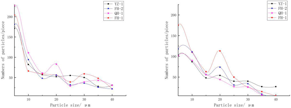
FIGURE 3. Particle size–quantity distribution statistics of various samples. All samples follow the distribution law that the larger the particle size is, the fewer the number of particles is, and more than 60% of the particles are concentrated within 15 um.

FIGURE 4. Statistical graph of the pore size–quantity distribution of various samples. After the seismic subsidence test, the large and medium pores are almost completely eliminated due to the application of the modified method and the effect of cyclic load.
According to the quantitative statistics of the particle size of the sample, no matter what kind of improvement method is used, it has the same rule as the original loess that the larger the particle size, the fewer the number of particles, and more than 60% of the particles are concentrated within 15 um. At the same time, the difference of the improvement methods also shows some differences: the dynamic compaction can identify and count the largest number of soil particles under the same area and, mainly, crush the medium and large particles above 30 um into 5–20 um. Particles: the number of particles is followed by the fly ash–modified sample. At the same time, it is noted that the curve has a small peak around 30 um. This phenomenon is not unrelated to the glass beads formed by fly ash at 30 um and the cement improvement method; although the number of small and medium particles has been increased to a certain extent and the number of particles with larger diameters has been reduced, the effect is slightly weaker than that of the other two methods.
Similarly, the quantitative statistics of the pore size of the sample show that the pore size–quantity distribution of dynamic compaction and fly ash and cement improvement methods have a relatively consistent trend with that of undisturbed loess, this is related to the particle size–quantity performance. The statistics also shows that the fly ash method significantly increased the number of pores within 10um, followed by the cement modification method. This is mainly due to the chemical method that generates fine particulate and increases the number of small and medium pores. At the same time, these chemicals are all over; filling the original particle pores has played a role in dividing the large pores, that is, the small number of large pores is divided into a large number of small and medium pores; the dynamic compaction method does not change the number of micro and small pores within 10 um significantly, but for 10 um the dynamic compaction method reduces the number of pores the most. In other words, the dynamic compaction method eliminates the medium and large pores more obviously, while the two chemical improvement methods mainly reduce the large pores or overhead pores above 50 um. There is even an increasing trend in the statistics of small and mesopores in range of 10–50 um.
Figure 5 shows the seismic subsidence coefficients of six types of loess samples when the vibration times N is gradually increased. Under the same dynamic stress, with the increase in vibration times, the residual strain of each type of specimen shows a gradual increase trend. The difference is that the seismic subsidence coefficient of undisturbed loess is the most sensitive to the increase in vibration times, followed by fly ash samples. The other four treatment methods greatly reduce the sensitivity of the seismic subsidence coefficient to the vibration times, and the seismic subsidence curves are very close, especially the dynamic compaction–cement method in the compound improvement method, which is not sensitive to the vibration times. Take the dynamic stress as 50 kPa and use the vibration times as the abscissa to draw the residual strain curve of the original and improved loess, as shown in Figure 6. It can be seen that regardless of the applied dynamic stress, the original sample shows strong sensitivity to the vibration times N, and the first 10 vibrations have accumulated more than 80% of the total residual deformation. This law is also consistent with the previous ones (Wang, 2003). Although different improvement methods have reduced its seismic subsidence to varying degrees, its residual deformation growth with the number of vibrations still has a similar law to that of the undisturbed soil, that is, the main deformation occurs in the first 10 vibrations, almost linearly increasing, and then the increase in the amount of earthquake subsidence gradually slowed down.

FIGURE 5. Seismic subsidence coefficients of original and improved loess samples under different vibration times.
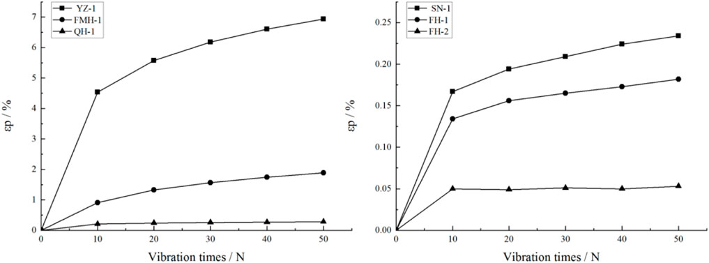
FIGURE 6. Vibration frequency and residual strain curves of original and improved soil samples.
The dynamic stress and residual strain curve of the sample is further analyzed after processing the dynamic stress and residual strain curve of the sample with 30 (fortification earthquake) and 40 (rare earthquake) times, respectively, under the action of strong earthquakes, as shown in Figure 7. Due to the large difference in the magnitude of the seismic subsidence caused by the effects of several improvements, in order to better show the difference between the curves, the original state, fly ash, and cement samples are used as a group to describe the seismic subsidence curve (Figure 8A). The dynamic compaction and two composite treatment samples are analyzed and described as a set (Figure 8B). The undisturbed loess sample exhibits strong shock sensitivity, and the shear deformation curve of the sample shows a sharp upward trend with the increase in dynamic stress. When the dynamic stress is loaded to 20–30 kPa, the strain reaches 3%, and when it is loaded to 50 kPa, the residual strain reaches 6%. Then the macroporous structure in the sample is destroyed (The microstructure is shown in Figure 2A), and the sample is macroscopically collapsed, so the residual strain value reaches to 6% after the test stops, and the value no longer rises.. The seismic subsidence curves of the two chemical improvement methods (fly ash and cement) mainly show three stages: 1) at the 0–20 kPa stage, the effect of the two improvement methods is almost the same, and the seismic subsidence of loess can be completely eliminated. 2) At the 20 kPa–60 kPa stage, both methods can increase the seismic performance of loess by more than 5 times, but the fly ash method begins to show the difference from the cement-soil method. The growth of the dynamic stress begins to accelerate, but the maximum residual deformation produced does not exceed 3% of the failure strain standard, which still has a good effect of improvement. 3) When the dynamic stress exceeds 60kPa, the residual deformation of the fly ash modification method produces a rapid growth stage with the application of dynamic stress. It is worth noting that the residual strain far exceeds the 3% strain standard, but it is different from the original test. In contrast, the sample body hardly produces fracture damage, can be supported until the dynamic stress is loaded above 120 kPa, and its deformation reaches 7% and above; the seismic subsidence curve of the cement-soil improvement method basically no longer increases with the continuous increase in the dynamic stress. When the dynamic stress reaches 120 kPa, the residual strain is still less than 1%. Figures 7, 8 on the right show the dynamic compaction, fly ash, fly ash when the dynamic load vibration times N are 30 (fortification earthquakes) and 40 (rare earthquakes) times, and the density is increased to 1.75 g/cm3. First of all, the residual strain of these three types of improvement methods is far superior to the first three types of specimens in magnitude, and their residual deformations do not exceed 1.5% under strong seismic loads. This result fully confirms that the increase in density has the improvement of seismic subsidence performance is of vital importance. In the treatment effect of the composite method, the cement-soil method after compaction is obviously the best and the fly ash method is the second. Especially for fly ash samples, the anti-seismic sinking effect is greatly enhanced after compaction treatment. When the dynamic stress reaches 100 kPa (N = 30), the residual deformation is only 0.54%, which is 6.28% lower than before compaction, which is almost eliminated seismic. Therefore, the test proves that the chemical modification method can effectively improve the seismic subsidence performance of the foundation, and the effect of tamping is the best.
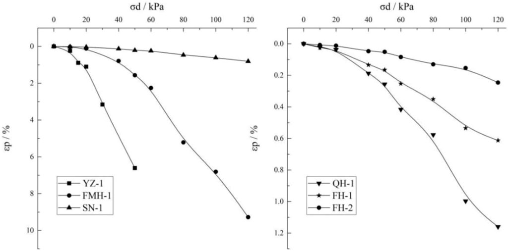
FIGURE 7. Original and improved loess seismic subsidence curve (N = 30).
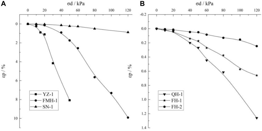
FIGURE 8. Seismic depression curve of original and improved loess (N = 40). (A) The original state, fly ash and cement samples. (B) The dynamic compaction and two composite treatment samples.
The research results show that the undisturbed loess samples have strong dynamic fragility. When the dynamic stress reaches about 50kPa, the residual strain reaches the peak value and the sample collapses, as shown in Figure 9A. Figure 9 shows the macroscopic phenomena of original and improved samples before and after the test. In the original sample, as shown in Figure 9A, it randomly contains calcareous nodules all over the sample; therefore, there are micro-cracks between the nodules and the surrounding soil. When stress is applied, the tips of the larger micro-cracks in the nodules are more likely to have stress concentration and rapidly expand, leading to the fracture of sample, and the position of the fractured surface often present an irregular form; the soil at the fracture site is loose and broken and dense micro-cracks are generated in other parts of the column. In the sample with fly ash, although the dynamic load caused considerable residual deformation of the sample, the sample did not appear to be broken or cracked but was manifested as the expansion of the column caused by the axial stress extrusion, as shown in Figure 9B. This also fully supports the role played by the “fly ash effect” in foundation treatment, that is, more than 70% of the glass beads contained therein play a role in compactness and homogenization and at the same time play a good lubricating effect. Therefore, although there will be residual deformation, it is shown as intermittent and gradual deformation so that sudden brittle failure will not occur. For the sample with cement, there is no visible change during the dynamic stress loading process. When the dynamic stress is loaded to the critical dynamic stress, the sample will undergo instantaneous segmental failure, as shown in Figure 9C. It shows that the column has X-shape through cracks, with obvious shear planes, and the whole process is abrupt. Due to the high strength of the two types of composite modified samples, there is no significant macroscopic deformation when loaded to 120 kPa, and the specimens have no significant height reduction phenomenon.
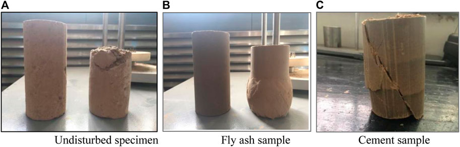
FIGURE 9. Macroscopic failure of the original, fly ash, and cement samples after the test. (A) Undisturbed specimen, (B) fly ash sample, and (C) cement sample.
In summary, it can be seen from the residual strain curve that the anti-seismic subsidence improvement methods for this seismic subsidence loess area are effective. Especially, it gives the qualitative evaluation of different improvements for Q3 loess under the conditions of fortified earthquake and rare earthquake. In microscopic view, physical improvement methods have the most obvious effect on eliminating large pores and overhead pore structures; chemical modification methods can generate unique glass beads or flocculated fine structures, which greatly increase the strength of the soil and play a role in filling, cementing, or buffering in strong earthquakes. From a dynamic point of view, under the conditions of frequent earthquakes, fortified earthquakes, and rare earthquakes, the amount of subsidence shows a non-linear growth trend with the increase in peak acceleration; therefore, for the actual engineering site, it is necessary to do a quantitative prediction of the amount of seismic subsidence under a specific earthquake intensity, and then take corresponding improvement measures according to suggestion in this study. In order to quantify the demand and better apply it to engineering practice, taking the sample collection area as an example, the amount of seismic subsidence under specific earthquake intensity is calculated: the total seismic subsidence of the site soil was obtained by the layered sum method based on the results of the indoor test, the seismic subsidence was predicted, and the effect evaluation of the modification treatment method was carried out. The ground motion parameters take the upper limit of the maximum horizontal ground acceleration
For the layered sum method, the amount of seismic subsidence is not only determined by the seismic subsidence coefficient but also inseparable from the soil thickness of the site. According to the seismic design standard, the calculated depth of foundation treatment was extended to 20 m. For sites with a thickness of less than 20m, the actual thickness is calculated. The calculation results and evaluation results of the seismic subsidence are shown in Table 4 (Department of Disaster Prevention, China Earthquake Administration, 1993).
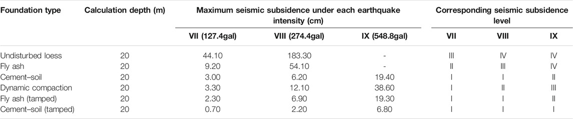
TABLE 4. Prediction results of seismic subsidence of loess field with different foundation treatment measures.
Combining the calculation results of the earthquake subsidence with Table 4 for analysis, for the undisturbed loess site, there is no doubt that it has extremely strong “seismic sensitivity,” which can cause severe earthquake subsidence in the foundation under frequent earthquakes. When the maximum horizontal ground acceleration
Loess in this site has extremely low water content. It is well known that loess has special structure, which makes it particularly sensitive to water. Therefore, the increase in loess moisture content caused by natural factors and human activities will increase the seismic subsidence and reduce the seismic subsidence performance. Therefore, the possible increase or decrease in water content of foundation soil and the drainage state of anti-seismic settlement measures should also be considered in the anti-seismic settlement treatment, which needs to be further studied.
The raw data supporting the conclusions of this article will be made available by the authors, without undue reservation.
PW is responsible for the overall implementation and writing manuscripts; SX is responsible for different earthquake in processing dynamic triaxial test, scanning electron microscopy (SEM) test, the implementation of the specific test, and data analysis; SS has carried on the theory of technical guidance to the whole manuscript. Graduate student, XL and ZQ as the main persons, participate in the test and manuscript finishing work.
This study was supported by the Central Public-Interest Scientific Institution Basic Research Fund (2020IESLZ07), the Joint funds for Earthquake Science (U1939209), the Key R&D Program in Gansu Province of China (18YF1FA101), and the Key Tasks of Emergency Youth of CEA(CEA_EDEM-2021).
The authors declare that the research was conducted in the absence of any commercial or financial relationships that could be construed as a potential conflict of interest.
All claims expressed in this article are solely those of the authors and do not necessarily represent those of their affiliated organizations or those of the publisher, the editors, and the reviewers. Any product that may be evaluated in this article, or claim that may be made by its manufacturer, is not guaranteed or endorsed by the publisher.
The authors are grateful to the members in the group, Shaofeng Chai, Shiyang Xu, Jinlian Ma, and Gaofeng Che, for their help in field tests and thankful to Wang for reviewing the manuscript.
Bruchon, J.-F., Pereira, J.-M., Vandamme, M., Lenoir, N., Delage, P., and Bornert, M. (2013). Full 3D Investigation and Characterisation of Capillary Collapse of a Loose Unsaturated Sand Using X-ray CT. Granular Matter 15 (06), 783–800. doi:10.1007/s10035-013-0452-6
Dal Ferro, N., Delmas, P., Duwig, C., Simonetti, G., and Morari, F. (2012). Coupling X-ray Microtomography and Mercury Intrusion Porosimetry to Quantify Aggregate Structures of a Cambisol under Different Fertilisation Treatments. Soil Tillage Res. 119, 13–21. doi:10.1016/j.still.2011.12.001
Deng, J., Wang, L., and Wu, Z. (2012). Acid Modification Method and Microstructure Analysis of Seismic Substance Deformation of Loess. Rock Soil Mech. 33 (12), 3624–3631. cnki: sun: ytlx.0.2012-12-017(In Chinese with English abstract).
Deng, J., Wang, L., and Zhang, Z. (2007). Microstructure Characteristics and Seismic Collapsibility of Loess. Chin. J. Geotechnical Eng. 29 (4), 542∼548. (In Chinese with English abstract). doi:10.3321/j.issn:1000-4548.2007.04.012
Department of Disaster Prevention, China Earthquake Administration (1993). Seismic Disaster Prediction and Evaluation Manual. Beijing: Seismological Press. (In Chinese).
Gao, G. (1980). Microstructure Analysis of Loess and its Application in Engineering Investigation. Eng. Invest. Surv. (06), 2583–2884. cnki:sun: gckc.0.1980-06-008 (In Chinese with English abstract).
Gao, G. (1980). Microstructure Classification and Collapsibility of Loess. Chin. Sci. 23 (12), 1203–1208. cnki:sun:jaxk.0.1980-12-008(In Chinese with English abstract).
Gao, M., Chen, G., Xie, F., Xu, X., Li, X., Yu, Y., et al. (2015). Zoning Map of Ground Motion Parameters in China. Beijing: Standards Press. (In Chinese).
Garratt-Reed, A., and Bell, D. (2005). Energy-dispersive X-ray Analysis in the Electron Microscope. Oxfordshire: BIOS Scientific Publishers Ltd.
Gu, T., Wang, J., Guo, L., Wu, D., and Li, K. (2011). Study on Microstructure Changes of Q3 Loess Based on Image Processing. Chin. J. Rock Mech. Eng. 30 (S1), 3185–3192. (In Chinese with English abstract).
Huang, Q. (1963). Discussion on Evaluation of Collapsible Loess Foundation. J. Civil Eng. 9 (2), 25–31. (In Chinese with English abstract).
Jiang, M., Zhang, F., Hu, H., Cui, Y., and Peng, J. (2014). Structural Characterization of Natural Loess and Remolded Loess under Triaxial Tests. Eng. Geology. 181, 249–260. doi:10.1016/j.enggeo.2014.07.021
Li, H., Tu, J., Wang, L., Mo, Y., Ma, L., Huo, H., et al. (2012). Local Standard of Gansu Province-Code for Seismic Design of Buildings. (In Chinese).
Li, L., Wang, L., and Wang, J. (2005). Quantitative Study of Microstructural Porosity of Loess in the Seismic Area of the Yongdeng M5.8 Earthquake. Chin. J. Seismological Res. 28 (3), 282–287. (In Chinese with English abstract). doi:10.3969/j.issn.1000-0666.2005.03.016
Lin, R.-S., Wang, X.-Y., Lee, H.-S., and Cho, H.-K. (2019). Hydration and Microstructure of Cement Pastes with Calcined Hwangtoh clay. Materials 12 (03), 458. doi:10.3390/ma12030458
Ng, C. W. W., Mu, Q. Y., and Zhou, C. (2017). Effects of Soil Structure on the Shear Behaviour of an Unsaturated Loess at Different Suctions and Temperatures. Can. Geotech. J. 54 (02), 270–279. doi:10.1139/cgj-2016-0272
Romero, E., and Simms, P. H. (2008). Microstructure Investigation in Unsaturated Soils: A Review with Special Attention to Contribution of Mercury Intrusion Porosimetry and Environmental Scanning Electron Microscopy. Geotech Geol. Eng. 26 (06), 705–727. doi:10.1007/s10706-008-9204-5
Shaanxi Comprehensive Survey Institute (1973). Characteristics of Loess and Loess like Soil in China and Evaluation Methods for Their Collapsibility and Bearing Capacity. Surv. Tech. Data 3 (3), 1–20. (In Chinese).
Shao, X., Zhang, H., and Tan, Y. (2018). Collapse Behavior and Microstructural Alteration of Remolded Loess under Graded Wetting Tests. Eng. Geology. 233, 11–22. doi:10.1016/j.enggeo.2017.11.025
Sheng, S., Dou, Y., Tao, X., Zhu, S., Xu, B., Li, Q., et al. (1999). Code for Geotechnical Testing. Beijing: China water resources and Hydropower Press. (In Chinese).
Shi, Y., and Li, L. (2003). Micro-analysis of Seismic Subsidence Characteristics of Loess. J. Rock Mech. Eng. 24 (2), 129–134. (In Chinese with English abstract). doi:10.3321/j.issn:1000-6915.2003.z2.061
Shi, Y., and Qiu, G. (2011). Constitutive Relationship of Seismic Subsidence of Loess Based on Microstructure. Chin. J. Geotechnical Eng. 33 (S1), 7–12. cnki:sun:ytgc.0.2011-S1-002 (In Chinese with English abstract).
Teng, Y., Zhang, Y., Yan, M., Zhang, F., Zhang, D., Yuan, N., et al. (2012). Technical Code for Foundation Treatment of Buildings. Beijing: China Construction Industry Press. (In Chinese).
Wang, J.-D., Li, P., Ma, Y., Vanapalli, S. K., and K, S. (2019). Evolution of Pore-Size Distribution of Intact Loess and Remolded Loess Due to Consolidation. J. Soils Sediments 19 (3), 1226–1238. doi:10.1007/s11368-018-2136-7
Wang, J., Wang, Q., Wang, P., Zhong, X., and Chai, S. (2013). Effect of Adding Amount of Fly Ash on Dynamic Constitutive Relationship of Modified Loess. Chin. J. Geotechnical Eng. 35 (S1), 156–160. cnki:sun: ytgc.0.2013-S1-025 (In Chinese with English abstract).
Wang, L., Deng, J., and Huang, Y. (2007). Microscopic Quantitative Analysis of Seismic Collapsibility of Loess. Chin. J. Rock Mech. Eng. 26 (Suppl. 1), 3025–3031. (In Chinese with English abstract). doi:10.3321/j.issn:1000-6915.2007.z1.066
Wang, L., and Zhang, Z. (1993). Estimation Method of Seismic Subsidence of Loess during Earthquake. J. Nat. Disasters 2 (3), 85–94. (In Chinese with English abstract).
Wang, Q., Liu, H., Ma, H., Wang, J., and Li, N. (2016). Anti-liquefaction Behavior and Mechanism of Cement-Stabilized Loess. Chin. J. Geotechnical Eng. 38 (11), 2128–2134. (In Chinese with English abstract). doi:10.11779/cjge201611025
Wang, Q. (2018). Study on the Earthquake Subsidence Characteristic of Loess and the Analysis and Evaluation Methods of Earthquake Subsidence in Loess Site. Xi’an: Xi'an University of Technology. (In Chinese with English abstract).
Wang, Y., and Lin, Z. (1990). Structural Characteristics and Physical and Mechanical Properties of Loess in China. Beijing: Science Press, 105–172. (In Chinese).
Wei, Y. (2019). Three-dimensional Microstructure Evolution and Collapsibility Mechanism of Loess under Water Action. Xi'an, China: Doctorates Discourse of ChangAn University. (In Chinese with English abstract).
Wen, B.-P., and Yan, Y.-J. (2014). Influence of Structure on Shear Characteristics of the Unsaturated Loess in Lanzhou, China. Eng. Geology. 168, 46–58. doi:10.1016/j.enggeo.2013.10.023
Xu, C., Wu, X., and Xu, X. (2018). Seismic Landslides in the Loess Plateau and its Adjacent Areas. J. Eng. Geology. 26 (Suppl. l), 260–273. (In Chinese with English abstract). doi:10.13544/j.cnki.jeg.2018208
Xu, S., Wu, Z., Zhao, W., and Zhao, T. (2017). Study of the Microscopic Pores of Structured Loess Based on MATLAB and IPP. China Earthquake Eng. J. 39 (1), 8094. (In Chinese with English abstract). doi:10.3969/j.issn.1000-0844.2017.01.0080
Xu, Y., and Guo, P. (2020). Disturbance Evolution Behavior of Loess Soil under Triaxial Compression. Adv. Civil Eng. 2020, 1–14. doi:10.1155/2020/4160898
Xu, Y., Guo, P., Wang, Y., Zhu, C.-W., Cheng, K., Lei, G., et al. (2021). Modelling the Triaxial Compression Behavior of Loess Using the Disturbed State Concept. Adv. Civil Eng. 2021, 1–17. doi:10.1155/2021/6638715
Xu, Y., Guo, P., Zhu, C., Lei, G., and Cheng, K. (2021). Experimental Investigation into Compressive Behaviour and Preconsolidation Pressure of Structured Loess at Different Moisture Contents. Geofluids 2021, 1–9. doi:10.1155/2021/5585392
Zhang, Z., Duan, R., Sun, C., Wang, L., Wang, J., Shi, Y., et al. (1999). Prediction of Loess Earthquake Disaster. Beijing: China Seismological Press. (In Chinese).
Zhang, K., and Ling, X. (2016). Geotechnical Seismic Engineering and Engineering Vibration. Beijing: Science Press. (In Chinese).
Zhang, Z., and Duan, R. (1986). “Discussion on Seismic Subsidence of Loess Sites in the north West of China during Earthquakes,” in Proceedings of the International Symposium on Engineering Geology Problems in Seismic Areas (Bari, Italy: Geologia Applicata ed Idrogeologia), 65–76.
Zhang, Z. (2016). Research on the Initiation Mechanism and Disaster Mode of Typical Seismic Loess Landslide. Wuhan: Doctoral Dissertation of China University of Geosciences. (In Chinese with English abstract).
Zhu, H., Ju, Y., Huang, C., Han, K., Qi, Y., Shi, M., et al. (2019). Pore Structure Variations across Structural Deformation of Silurian Longmaxi Shale: An Example from the Chuandong Thrust-fold Belt. Fuel 241, 914–932. doi:10.1016/j.fuel.2018.12.108
Keywords: seismic subsidence loess, modification treatment, mesoscopic features, strong earthquake, seismic performance
Citation: Wang P, Xu S, Shao S, Wang H, Li X and Qian Z (2022) Mesoscopic Characteristics and Performance Evaluation of Loess Treated by Different Anti-Seismic Subsidence Technologies. Front. Earth Sci. 9:762508. doi: 10.3389/feart.2021.762508
Received: 22 August 2021; Accepted: 17 November 2021;
Published: 21 January 2022.
Edited by:
Yueren Xu, China Earthquake Administration, ChinaReviewed by:
Panpan Guo, Zhejiang University, ChinaCopyright © 2022 Wang, Xu, Shao, Wang, Li and Qian. This is an open-access article distributed under the terms of the Creative Commons Attribution License (CC BY). The use, distribution or reproduction in other forums is permitted, provided the original author(s) and the copyright owner(s) are credited and that the original publication in this journal is cited, in accordance with accepted academic practice. No use, distribution or reproduction is permitted which does not comply with these terms.
*Correspondence: Ping Wang, bGFuemhvdXdhbmdfcEAxMjYuY29t; Shengjun Shao, c2pzaGFvQHhhdXQuZWR1LmNu
Disclaimer: All claims expressed in this article are solely those of the authors and do not necessarily represent those of their affiliated organizations, or those of the publisher, the editors and the reviewers. Any product that may be evaluated in this article or claim that may be made by its manufacturer is not guaranteed or endorsed by the publisher.
Research integrity at Frontiers
Learn more about the work of our research integrity team to safeguard the quality of each article we publish.