
94% of researchers rate our articles as excellent or good
Learn more about the work of our research integrity team to safeguard the quality of each article we publish.
Find out more
ORIGINAL RESEARCH article
Front. Earth Sci., 16 December 2021
Sec. Geohazards and Georisks
Volume 9 - 2021 | https://doi.org/10.3389/feart.2021.761455
This article is part of the Research TopicIntegration of State-of-Art Techniques for Landslide Hazard Assessment and for the Mitigation Caused by the Subsequent Multimodal DisasterView all 11 articles
This study proposes a numerical coupling approach to simulate seismic signals of rockfalls and conducts a parametric analysis to explore the characteristics of the seismic signals generated by rockfalls. To validate the approach, three field rockfall tests were selected for comparison. The rockfall velocity, duration, seismic frequency, Husid plot, Arias intensity, and spectrogram of the seismic signals were compared. We found that friction between rocks and the ground affects rock falling behavior. In addition, the local damping and Rayleigh damping assignments in the numerical model have strong effects on the simulation results. The volume of the falling rock and the falling speed of the rock affect the Arias intensity. The coupling approach proposed could be extended and can potentially be used as a useful tool in rockfall hazard estimations.
Seismic signals induced by rockfalls are transmitted over great distances and can therefore be monitored remotely by accelerometers or geophones. The movement processes of rockfall events can be well correlated to their seismic signals. Once the characteristics of the signals are analyzed, significant information about the rockfall process such as scale and velocity can be better evaluated (Provost et al., 2018; Schöpa et al., 2018). In particular, their distinct seismic frequency, duration, and spectrograms can be analyzed.
Although seismic signals are most useful for analysis if they are recorded from actual rockfalls (Vilajosana et al., 2008; Schimmel et al., 2017), it may not always be possible to successfully acquire the signals from natural rockfalls due to various constraints. Large-scale rockfall test can be conducted but are difficult to set up and control, in addition to their high cost. Small-scale rockfall tests are easier to carry out several times but still require manpower, funds, and space. Therefore, it is necessary to develop a numerical model to obtain sufficient synthetic seismic signals of rockfalls for systematic investigations and parametrical studies.
Particle flow code in 2 dimensions (PFC2D; Itasca Consulting Group, 2008) is a discrete element code and can calculate finite displacements and rotations of discrete elements and automatically recognize new contacts for rigid circular particles. Interaction between particles is treated as a dynamic process. The dynamic process is solved by an explicit finite-difference method. It is appropriate for simulating the movement of rock masses over large distances. For example, Tang et al. (2009) applied the PFC to model the Tsaoling large-scale landslide that resulted from the 1999 Chichi ML 7.3 earthquake. Yuan et al. (2014) utilized the PFC to simulate the Donghekou landslide triggered by the 2008 Wenchuan earthquake. The displacement of particles was traced to understand the landslide process. Deng et al. (2016) used the PFC to simulate the sliding processes of the Wenjiagou rock avalanche due to the 2008 Wenchuan earthquake. They classified the process into four stages: failure rupture, projectile motion, granular debris flow, and debris mass accumulation. Yan et al. (2020) applied the PFC to reconstruct sliding processes and classified the landslide process into five stages: stationary, slipping, transition, entrainment–transportation, and deposition.
From the aforementioned literature, it is evident that the PFC is capable of simulating various landslide processes and their deposition very well. However, these researchers did not simulate the seismic signals induced by the landslides. To facilitate the simulation of the seismic signals induced by a landslide, Feng et al. (2017) and Feng et al. (2021) coupled the PFC and fast Lagrangian analysis of continua (FLAC, Itasca, Inc., 2011) (Itasca Consulting Group, 2011) to simulate large-scale landslides and obtained the seismic signals caused by the landslides from the numerical model. They used the PFC to reconstruct the landslide process and FLAC to compute the seismic signals induced by the landslide.
In this study, we propose and establish a numerical coupling approach using the PFC and FLAC to simulate the seismic signals of rockfalls and perform a parametric study. For assessment purposes, three rockfall field tests from Feng and Zhuang (2021) were selected for comparison with the numerical results. The reasons for the discrepancies between the numerical simulations and the field tests are discussed.
The proposed numerical coupling approach can be modified for various sizes and types of landslide movement by altering the properties and scales of the modeled moving materials in the PFC. Therefore, the coupling approach can be further extended to study the characteristics of seismic signals corresponding to various landslide processes and behaviors.
In order to test the coupled simulations, three field test results were chosen from Feng and Zhuang (2021) for comparison. The path of the rockfall consisted of a slope, road, creek bank, and creek bed. The dimensions of the test site and positions of 3 accelerometers are shown in Figure 1. Accelerometers A1–A3 (Acc. A1–A3, hereafter) were installed approximately parallel to the path of the rockfall.
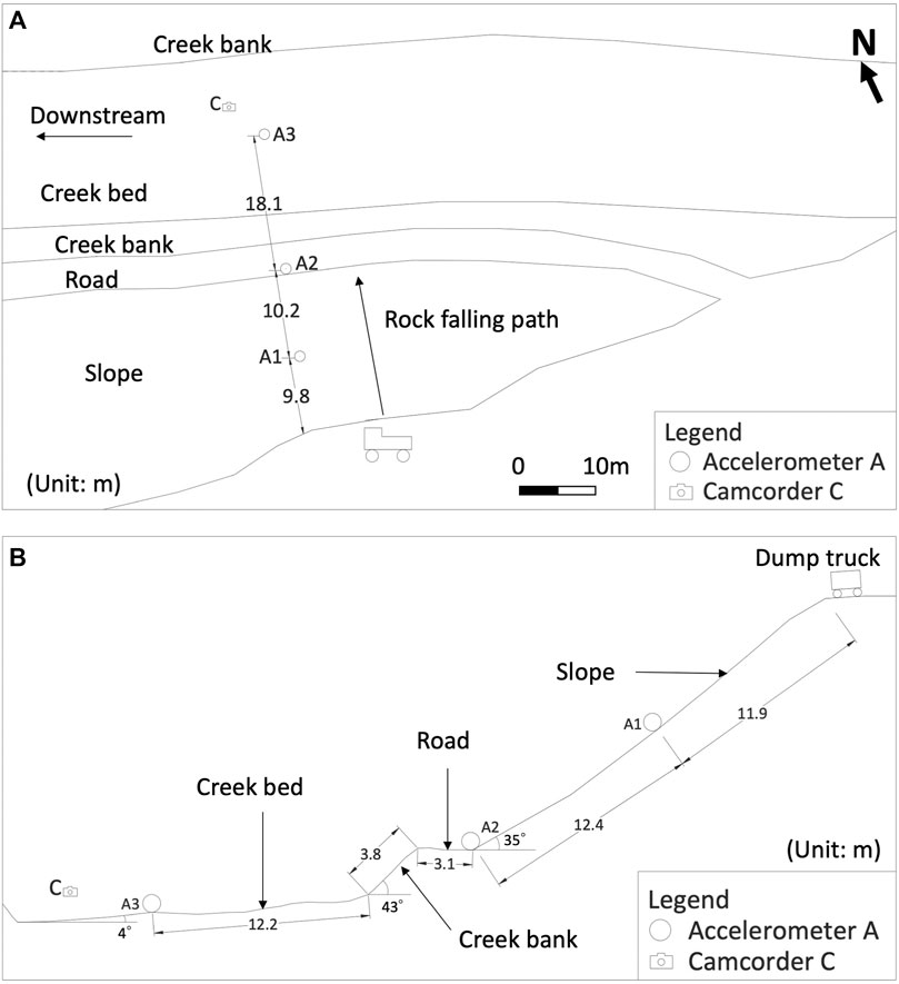
FIGURE 1. Setup of the tests and layout of the sensors (A) top view, (B) side view (modified from Feng and Zhuang (2021)).
The three field tests included a single large rockfall test, single small rockfall test, and rock mixture fall test. The size of the large rock was approximately 1.60 × 1.61 × 1.03 m across three of its axes and the small rock was approximately 0.91 × 0.98 × 0.72 m. The rock mixture consisted of rocks 0.3–0.8 m in diameter (approximate 4.5 m3). The rock block or rock mixtures were dumped from a truck at the crest and fell, bounced, or rolled to the downslope and creek. The serial snap pictures of the three field tests are shown in Figure 2.
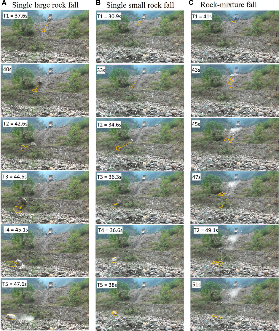
FIGURE 2. Serial snap pictures of the three field tests: (A) the single large rockfall (Test 2), (B) the single small rockfall (Test 5), (C) the rock mixture fall (Test 7). (The pictures were captured from the test films of Feng and Zhuang (2021). The test films can be viewed at https://link.springer.com/article/10.1007/s10346-021-01748-9).
A numerical coupling model was established to simulate the processes of the rockfall tests using the PFC and FLAC. A numerical parametrical study was also performed to investigate the differences in falling velocity, energy produced, and acceleration of a rock block fall due to variation of parameters. The coupling methodology used was that of Feng et al. (2017), who used the PFC to simulate the movement of the rock particles and used FLAC to simulate the seismic signals for a large-scale landslide.
The PFC is suitable for modeling the movement and interaction of particles, while also being excellent in the simulation of rockfalls, including rock rolling/bouncing processes. PFC modeling involves particle elements and “wall” elements. The rock masses are modeled by the particles. The wall elements are the boundary that defines the particle movement; for example, the ground surface can be represented by wall elements. There are many microscopic parameters in the PFC that are required to simulate particle movement properly, including the friction between particles, friction between particles and the “wall” elements, local damping, and viscous damping (Tang et al., 2009; Lo et al., 2011). Altering the parameters will result in different particle movement behaviors and outcomes. Therefore, the parameters were first set by referring to the aforementioned literature and then adjusted with many “trial-and-error” back-analyses to fit the rockfall processes of the field tests, including falling, bouncing, rolling, and final deposition. The parameters that were considered best describing the field tests are shown in Table 1.
A schematic view of the PFC models for the field tests is shown in Figure 3. In total, 80 wall elements were used to represent the ground surface, which are the slope, road, creek bank, and creek bed. The rock block was modeled by the “clump” command of the PFC to assemble particles to form the shape of the two single test rocks. The clumped model rock is a rigid object with almost no deformation. The single large rock was modeled to be approximately 1.25 m in diameter and was modelled using 25 particles clumped together, while the single small rock was 0.95 m in diameter and composed of 15 particles. However, the two numerical model rocks were not circular in shape to mimic the shape of the two rock blocks in the tests. For the modeling of the rock mixture, 224 particles were clumped into 18 small model rocks and placed together in the model dump truck which was also modeled by wall elements. The model rocks and rock mixture were dumped from the slope crest to simulate the falling, rolling, and bouncing processes.
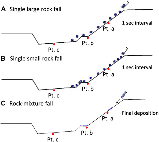
FIGURE 3. Schematic of PFC models for the tests. Pt. (a–c) are the monitoring points in FLAC. The particle traces shown are in 1 s interval for the rock block falls and the final deposition for rock mixture fall.
FLAC is a finite difference code suitable for dynamic analysis to model seismic waves traveling in geomaterial continua. To achieve the simulation of seismic waves induced by the particle falling process, the PFC had to be coupled with FLAC. This strategy takes advantage of each code.
The setup of the FLAC model includes 80 * 40 = 3,200 finite difference zones. The sizes of the zones varied from 1 m * 2 m at the bottom to 1 m * 0.6 m at the top of the mesh, as shown in Figure 4. Three materials were modeled in FLAC: the stratum, the road, and the revetment. As the shear wave velocity was estimated from the rock block fall tests, it could then be used to estimate the shear modulus of the stratum. The soils of the road were compacted and were stiffer than the stratum. The revetment was made from rocks and was stiffer than the road. Therefore, the properties of the three materials were assigned accordingly in the FLAC model and are listed in Table 2.
The left- and right-side boundaries of the FLAC mesh were assigned as free-field boundaries so that the stress waves were not reflected by the boundaries. Free-field boundaries are one of the various kinds of “absorbing” boundaries in dynamic simulations. The bottom of the mesh was assigned as a fixed boundary. Rayleigh damping was assigned for material damping as it can also reduce the reflection of stress waves from the boundary.
While setting up the mesh of the FLAC model, the coordinates of the 80 zones’ top surface had to be identical to the coordinates of the 80 wall elements in the PFC model to act as the coupling nodes for exchanging data between the PFC and FLAC code (Figure 4). Codes written in the computer language, FISH, organize the data exchange between the PFC and FLAC. During coupling calculations data are transferred between the two codes by “Socket I/O.” In each timestep (cycle), FLAC passes the velocities of the coupling nodes through the Socket I/O to PFC. After calculation, the PFC then passes forces of the wall elements also through the Socket I/O to FLAC, and this then completes a coupling cycle (Itasca Consulting Group, Inc., 2011) (Itasca Consulting Group, 2011). Later, the coupling cycles were repeated until the simulation was complete. During the coupling calculation, the timestep (delta t) and stepping cycles had to be identical across the two codes. Also, to allow stable coupling calculation, the timestep was set as small as
In the simulation, time series of seismic signals at selected nodes of the FLAC mesh were recorded and thus the simulation results can be compared with the field tests. Three monitoring points a, b, and c, were assigned in the FLAC model to trace the acceleration time series for analyses. However, the simulation is two-dimensional, meaning that particles rolling over the surface nodes or impacting the surface nodes, and generate much higher amplitudes of seismic signals than those of the field tests. To avoid excessively high seismic acceleration of the surface nodes due to direct impact, points a, b, and c in the model were located one node beneath the ground surface nodes. They corresponded to the locations of Acc. A1, A2, and A3, respectively, and were set up in the field tests.
The Hilbert–Huang transform (HHT, Huang et al., 1998) (Huang et al., 1998) is very well known and has been extensively applied in processing all kinds of signals in many research fields since its development in 1998. The HHT includes the calculation of empirical mode decomposition (EMD) and Hilbert transform (HT). EMD can decompose an original signal into many intrinsic mode functions (IMFs) and a residual signal. A time–frequency spectrum can be calculated by applying Hilbert transform to each IMF. The spectrum is very helpful when interpreting the characteristics of the signal and the relationship between spectral magnitude and instantaneous frequency over time. The average frequency of each IMF can be obtained. Also, the percentage power of each IMF can be calculated to identify the energy percentage of each IMF to the energy of the original signal. There are other methods for seismic signal analysis, such as short-time Fourier transform (STFT) and wavelet transform. However, the HHT is good for processing non-stationary and non-linear data. Therefore, the HHT was employed to process the seismic signals in this study using Visual Signal ver. 1.5 (AnCad, Inc., 2013) (AnCad, Inc., 2013).
Arias (1970) (Arias and Hansen, 1970) proposed Arias intensity (IA) to evaluate the intensity of a ground motion. IA is a reliable ground motion parameter. IA is defined as the square of the acceleration integrated over the duration of the signal, as shown in Eq. 1:
where g is the gravity (9.81 m/sec2), a(t) is the time-dependent acceleration, and Td is the duration of the acceleration signal.
A Husid plot is a time history of the normalized IA and can be obtained during integration of IA. A Husid plot is sometimes used to define the duration of a strong motion. Feng et al. (2021) and Feng et al. (2020) also successfully applied Husid plots to estimate the increased energy (power) during landslides. Therefore, Husid plots were used to compare the energy development in the rockfalls discussed in this study. SeismoSignal software (Seismosoft, Ltd., 2020) (Seismosoft, Ltd, 2020) was employed to calculate IA and Husid plots in this study.
Three simulations (SIM-1, SIM-2, and SIM-3) were first performed for the single large rockfall, single small rockfall, and rock mixture fall. Correspondingly, three test results (Test 2, Test 5, and Test 7) from Feng and Zhuang (2021) were chosen for comparison.
The 3 simulation results and the 3 test results are summarized in Table 3. For each simulation and test, the estimated falling duration and averaged falling velocity of the rock block falls were estimated as well as the Arias intensities of the signals acquired at the numerical monitoring points a, b, and c and recorded by Acc. A1–A3 during the tests were listed respectively for reference.
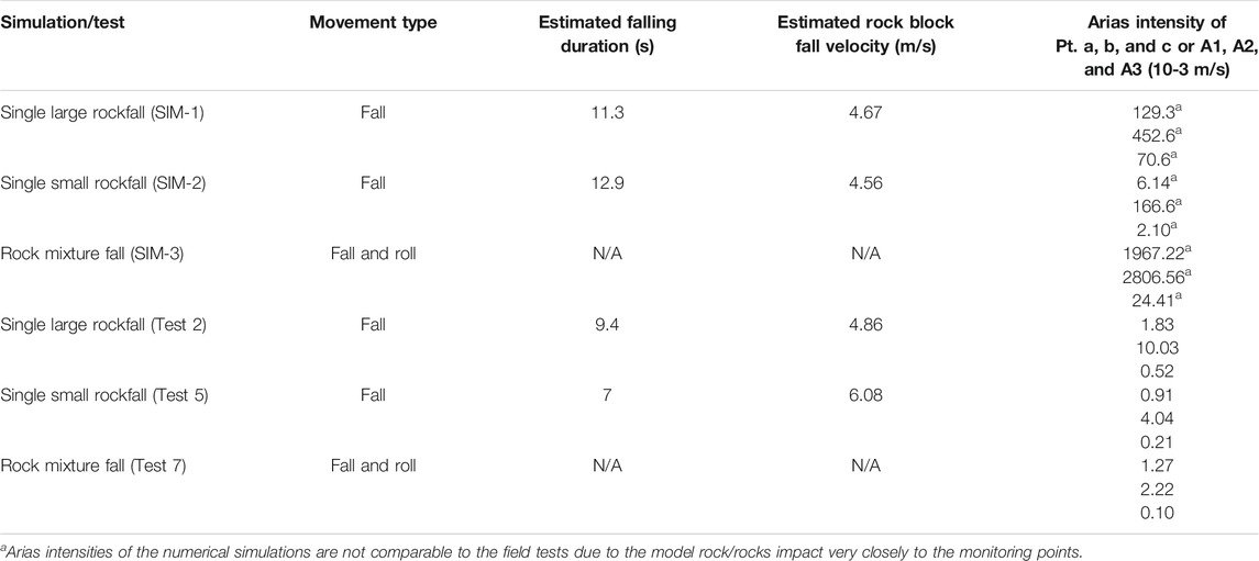
TABLE 3. Simulation results from this study and the field test results from Feng and Zhuang (2021).
Figure 5 shows the SIM-1 simulated signals alongside the time-–frequency spectra of the single large rockfall. Figure 6 depicts the seismic signals alongside time–frequency spectra of the single large rockfall test (Test 2) for comparison with Figure 5. The T1–T5 marked in Figure 6 are the timings of when the rock arrives at certain locations on the slope, bank, and creek bed and are explained in the figure caption. The timings also correspond to the snap pictures in Figure 3.
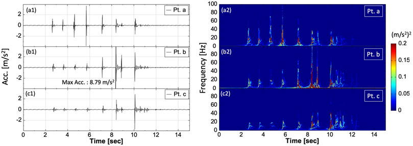
FIGURE 5. Seismic signals and their corresponding time–frequency spectra with respect to the monitored points a, b, and c of the single large rockfall simulation.
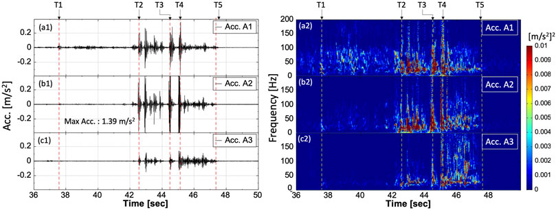
FIGURE 6. Seismic signals and their corresponding time–frequency spectra of the single large rockfall test (Test 2). T1: 37.6 s, the rock first impacting on the slope; T2: 42.6 s, the rock arriving the slope toe; T3: 44.6 s, the rock impacting on the bank; T4: 45.1 s, the rock impacting on the creek bed; and T5: 47.6 s, the rock stop.
Similarly, Figures 7, 8 present the resulting signals and spectra for the single small rockfall simulation SIM-2 and Test 5; Figures 9, 10 present the results of the rock mixture fall simulation SIM-3 and Test 7.
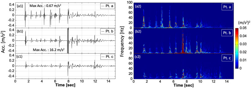
FIGURE 7. Seismic signals and their corresponding time–frequency spectra with respect to the monitored points a, b, and c of the single small rockfall simulation.
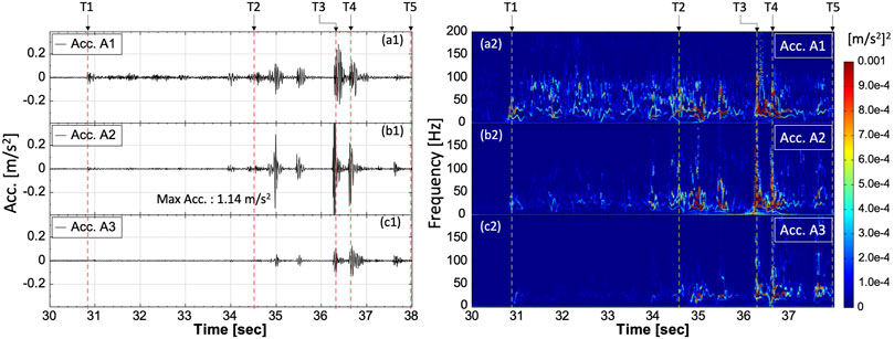
FIGURE 8. Seismic signals and their corresponding time-–frequency spectra of the single small rockfall test (Test 5). T1: 30.9 s, the rock first impacting on the slope; T2: 34.6 s, the rock arriving at the slope toe; T3: 36.3 s, the rock impacting on the bank; T4: 36.6 s, the rock impacting on the creek bed; and T5: 38.0 s, the rock stop.
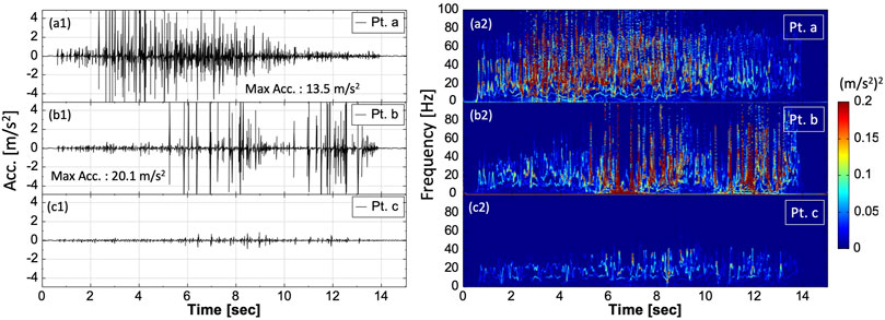
FIGURE 9. Seismic signals and their corresponding time–frequency spectra with respect to the monitored points a, b, and c of the rock mixture fall simulation.
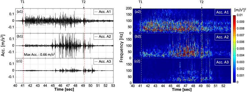
FIGURE 10. Seismic signals and their corresponding time–frequency spectra of the rock mixture fall test (Test 7). T1: 41.0 s, rock mixtures impacting on the slope; T2: 49.1 s, the rocks impacting on the creek bed.
After many trial-and-error simulations of coupling PFC and FLAC, it was found that the rock size, shape, friction, and local damping of a rock block fall have the most influence on the simulation results. According to Itasca Consulting Group, Inc. (2008) (Itasca Consulting Group, 2008), the local damping used in the PFC is achieved by adding a damping force term to the equations of motion. The damping force is controlled by a damping constant. This form of damping has the advantage that only the accelerating motion is damped; the damping constant is non-dimensional, and the damping is frequency-independent.
From our preliminary simulations, it was found that the larger the rock block, the greater the momentum, and the longer the resulting rolling distance. The rounder the shape of the rock, the less bouncing occurred, resulting in more rolling movement. The more irregular the shape of the rock (with an angular shape), the greater will be the occurrence of bouncing. The presence of a flat face on the model rock could also cause it to suddenly stop when the flat surface of the rock made contact with the ground. Therefore, when simulating a rock block fall, the shape of the model rock should reflect that of the rock block used in the tests as closely as possible.
The friction parameter of the wall elements in the PFC will affect the rolling distance and behavior of rockfall. If friction is set too low, the rock will slide and not roll, while if friction is set too high, the rock will come to a stop on the slope and cease to move. In the PFC, the local damping setting will affect the distance of rock movement and bounce height. The smaller the local damping value assigned, the greater the distance of movement will be and the more obvious the incidences of bouncing will be. Therefore, a set of parameters should be assigned in the PFC to allow the model rocks to fall/roll/bounce from top of the slope to the creek bed in a similar way to the field tests. The three simulations (SIM-1–3) were considered successful without too many occurrences of bouncing during the falling processes and were closely reflected the field tests.
In this study, local damping was adjusted to make the bouncing of the rocks fit the field tests; however, this resulted in a decrease in the falling speed of the simulated rocks. Therefore, the falling speeds of a rock block fall in SIM-1 and SIM-2 was slower than Test 2 and Test 5, respectively (Table 3).
The surface wave velocity of the numerical mesh was estimated to be 242 m/s by using the differences in arrival time and distance between points a and c for SIM-1. The surface wave velocity calculated from SIM-2 was 263.6 m/s. These two velocities are fairly close to the field test estimated average surface wave velocity of 291.4 m/s (Feng and Zhuang, 2021). This also supports that the estimation of the shear modulus of the stratum is quite realistic.
Most of the simulated signals of SIM-1 and SIM-2 have obvious “aperiodical impulse signals” (Figures 5, 7), which is the result of the rock bouncing on the ground surface. In Tests 2 and 5, such “aperiodical impulse signals” were also observed when the rock bounced on the road, bank, and creek bed (Figures 6, 8).
The signals and time–frequency spectra of SIM-3 Pt. a and Test 7 Acc. A1 in Figure 9a and Figure 10a are continuous due to percussion, rolling, and falling of the rock mixture. However, in field Test 7 when the rock mixture rolled down, debris on the slope surface moved downward too, resulting in a longer signal duration at Test 7 Acc. A1. The numerical simulation SIM-3 only contains rock mixture itself (i.e., the debris particles were not simulated) causing the duration of the SIM-3 signal to be shorter than that of Test 7 Acc. A1.
Average frequencies were also obtained from points a, b, and c for SIM-1 to SIM-3 (Table 4). In Table 4, only the major signal components (i.e., major IMFs) were selected from the field tests for frequency calculation based on higher energy content in the IMFs and screening of the noise signals from the environment. The average frequencies of the numerical simulations of rock block falls (SIM-1 and -2) were much lower than those of field tests 2 and 5. The reason for this is that the rock in the rock block fall tests mainly rolled on the slope and continued to generate high-frequency seismic waves from the slope. However, the average frequency of the signals of point a and b of SIM-3 are very close to those of Test 7 which indicates that the simulation of the rock mixture fall process is reflective of field Test 7.
Discrepancies were observed between the results of the numerical simulations and the field tests. The main source of the differences is that the numerical simulation is two-dimensional, resulting in the model rock/rocks contacting the monitoring points directly, causing large seismic signals. In addition, the model rock rolls on only one axis, but the rolling axis of the rock in the field tests could change randomly and did not necessarily adhere to a straight path. Moreover, the surface soils of the slope in the field tests were taken along by the falling rock, which was not accounted for in the simulations. All of these reasons result in differences between the numerical simulations and the field tests. Feng et al. (2017) indicated that the simulated seismic signals were obviously larger than those from station records because of the direct impacts of the particles on the mesh nodes.
The SIM-1 single large rockfall simulation was chosen as the baseline case in terms of parameters to discuss the influence of the friction coefficient of wall, bulk modulus, and Rayleigh damping on the numerical simulations. The results and parameters used are summarized in Table 5. The friction coefficient of wall elements in SIM-4, -5, and -6 were varied in the PFC, that is, by varying the friction of the modeled ground surface. It was observed that the greater the friction, the slower the rockfall velocity is, that is, friction slows the falling of the rock. However, due to increasing wall friction, the rock impacts on the slope (which is close to Pt. a) more often, increasing the Arias intensity of Pt. a. The acceleration amplitudes of Pt. a during the first impact also increased with increasing wall friction.
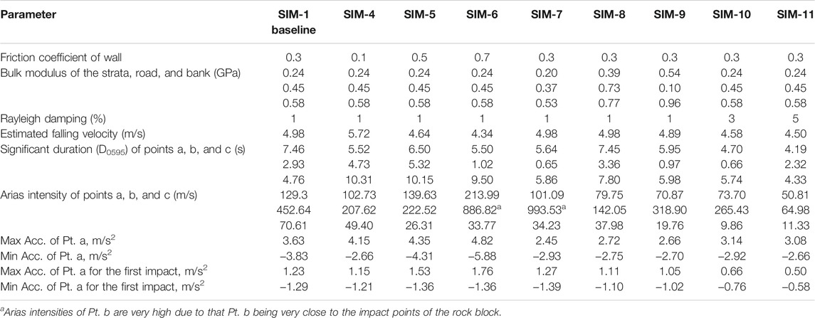
TABLE 5. Parameters settings and results of the parametrical study for single large rockfall. The friction coefficient of walls, bulk modulus, and Rayleigh damping were varied.
The bulk modulus of the strata, road, and bank in FLAC was varied in SIM-7, -8 and -9. The results show that the bulk modulus had little effect on the rockfall velocity, that is, the rockfall velocities of SIM-1, -7, and -8 greatly altered. It was found that the larger the bulk modulus, the smaller the acceleration amplitude of the first impact of the rock. As bulk modulus increases, dynamic deformation of the geomaterials decreases, resulting in less acceleration.
Rayleigh damping in FLAC was varied in SIM-10 and -11. The comparison results show that the larger the Rayleigh damping, the smaller the amplitude of the seismic signal and the smaller the Arias intensity, which indicates that Rayleigh damping models the dissipation of energy. There are limitations of modeling with Rayleigh damping in FLAC. Rayleigh damping is frequency dependent and requires the selection of a central frequency as an input parameter. The central frequency is neither the natural frequency of the stratum nor the major frequency of the external exciting forces but a combination of both (Mánica et al., 2014). We used a central frequency of 1 Hz for the Rayleigh damping setting in FLAC, but we were not able to calibrate it due to a lack of data. Also, while Rayleigh is assigned in FLAC, its use results in increase calculation times as it requires a smaller timestep (delta t) for a stable solution.
Figure 11 shows the Husid plots of seismic signals from Pt. c and Acc. 3, located in the creek bed, of simulations and field tests. The time zero for the Husid plot is the time when the rock first touched the ground surface.

FIGURE 11. Husid plots of seismic signals form Pt. c and Acc. 3: (A) single large rockfall, (B) single small rockfall, and (C) rock mixture fall.
The Husid plots for single large rockfalls of SIM-1 and Test 2 are shown in Figure 11A. The significant durations of SIM-1 and Test 2 are 4.76 and 3.95 s, respectively. The significant duration (D0595) of a signal is defined as the time interval between 5 and 95% accumulated Arias intensity. It can be observed that when the rock rolled on the slope, the accumulated Arias intensity increased very slowly. However, when the rock impacted the road, bank, or the creek bed, the accumulated Arias intensity increased rapidly. Since Pt. c and Acc. A3 are located in the creek bed, a large kink will appear in the Husid plots when the falling rock impacts the creek bed. It was found that when the rock was still rolling on the slope in SIM-1, the Arias intensity increment was larger than the field Test 2 as in Figure 11A. The reasons could be: 1) the energy of the rock rolling on the slope in the field tests was dissipated by the soft surface soils. 2) increased bouncing movement on the slope of SIM-1 resulting in greater seismic energy.
It can be seen from Table 3 that the Arias intensities of the simulations were much higher than those of the field tests. This was caused by the fact that the monitoring points of the numerical simulations were very close to the impact points of the model rock. The accelerometers of the field tests were at a distance >10 m from the rolling path of the rock. Moreover, the monitoring points of simulations and the rolling path of the model rock are in-line, that is, the model rock was able to roll over or impact the monitoring points directly.
Figure 11B shows the Husid plots for the single small rockfall SIM-2 and Test 5. The significant duration of Test 5 is 2.60 s. The significant duration of SIM-2 is comparatively long (11.01 s) and can be observed from Figure 11B. From the simulation film, it can be understood that the rock rolled slowly on the slope in SIM-2, impacted the road, and continued to slowly roll on the bank, resulting in an elongated significant duration. Compared with SIM-1 from its simulation film, the rock did not roll on the bank; it instead bounced from the road, impacted the creek bed, and came to a stop, resulting in a shorter significant duration. Similarly, when the rock was still rolling on the slope in SIM-2, the Arias intensity increment was larger than in field Test 5 as shown in Figure 11B.
Figure 11C shows the Husid plots for rock mixture fall SIM-3 and Test 7. The significant duration of Test 7 was 5.21 s, while the significant duration of SIM-3 was also rather long at 10.3 s. That is because the rocks slowly and sporadically rolled down the slope, and this can be observed from the simulation film of SIM-3. Also, the Husid plot of SIM-3 shows that the Arias intensity was still increasing between 12and 15 s. Generally, the rate of increase in the Arias intensity of the rock mixture fall tests is slower than that of the rock block fall tests and with less kinks in the Husid plots.
This study proposed a numerical coupling approach to simulate seismic signals of rockfalls to discuss the characteristics of seismic signals generated by rockfalls. The PFC was used to construct the rockfall mass and simulate the falling processes. The FLAC code was coupled with the PFC to calculate seismic signals induced by the rockfalls. Three field rockfall test results were used for comparison with the simulated results and to validate the numerical results of the approach. Hilbert–Huang transform (HHT) was employed to analyze the seismic signals to obtain the frequency, intrinsic mode functions, and time–frequency spectra of the seismic signals. We discussed the rockfall velocity, duration, seismic frequency, Husid plot, Arias intensity, and the characteristics of the time–frequency spectra of the seismic signals in detail. Finally, a numerical parametric study was performed to explore the parameters that were most sensitive with regard to their influence on the numerical simulations.
The results showed that the waveform patterns of the seismic signals of the simulations were similar to those of the field tests in general. The velocities of the surface waves of the stratum in the numerical models were estimated and compared well with the velocity obtained by the single large rock fall test. The friction of the ground surface affects the rolling distance and behavior of rockfalls. When we selected the friction parameter, we shall refer to the conditions of the surface soil and vegetation and with a trial-and-error approach. Due to better falling process simulation, the time-frequency spectra of the rock-mixture fall simulation was closer to that of the field tests than in the single rock fall simulation. Therefore, the closer to the real-life process of the rock fall the simulation was, the closer the characteristics of seismic signals were to the field results in general. Damping parameters in the numerical simulations influenced the kinematic behavior of the rock fall significantly. The local damping setting in PFC affects the distance of rock movement and bounce height. The Rayleigh damping in FLAC has a strong effect on energy dissipation. The Arias intensity and Husid plot reflect the seismic energy received by an accelerometer. They are affected by rock fall volume and falling speed.
The numerical coupling approach can be further extended to general landslide movements such as translational slides, rock flows, and various sizes of rock mass falls to study the seismic characteristics and movement processes. This will assist in interpretation of the seismic records of various landslide events acquired from seismic stations such that the evaluation of landslide movement types and magnitudes based on seismic signals can maturate.
The raw data supporting the conclusions of this article will be made available by the authors, without undue reservation.
Z-YF contributed to methodology, formal analysis, investigation, supervision, and writing original draft. Z-RS helped with data curation, formal analysis, visualization, and writing original draft. R-CZ assisted with data curation, formal analysis, visualization, and writing original draft.
The authors acknowledge the Ministry of Science and Technology, Taiwan, R.O.C, for providing research funding (Grant Number: 108-2625-M-005-006).
The authors declare that the research was conducted in the absence of any commercial or financial relationships that could be construed as a potential conflict of interest.
All claims expressed in this article are solely those of the authors and do not necessarily represent those of their affiliated organizations, or those of the publisher, the editors, and the reviewers. Any product that may be evaluated in this article, or claim that may be made by its manufacturer, is not guaranteed or endorsed by the publisher.
The authors thank Hallam Atherton for reviewing the manuscript style.
The Supplementary Material for this article can be found online at: https://www.frontiersin.org/articles/10.3389/feart.2021.761455/full#supplementary-material
Supplementary Film SIM-1 | Numerical simulation for the single large rockfall SIM-1.
Supplementary Film SIM-2 | Numerical simulation for the single small rockfall SIM-2.
Supplementary Film SIM-3 | Numerical simulation for the rock mixture fall SIM-3.
AnCad Inc (2013). Visual Signal Reference Guide Version 1.5. Available at: http://www.ancad.com.tw/VisualSignal/doc/1.5/RefGuide.html (Accessed June 28, 2021).
Arias, A. (1970). “A Measure of Earthquake Intensity,” in Seismic Design for Nuclear Power Plants. Editor RJ Hansen (Cambridge: MIT Press), 438–483.
Deng, Q., Gong, L., Zhang, L., Yuan, R., Xue, Y., Geng, X., et al. (2016). Simulating Dynamic Processes and Hypermobility Mechanisms of the Wenjiagou Rock Avalanche Triggered by the 2008 Wenchuan Earthquake Using Discrete Element Modelling. Bull. Eng. Geol. Environ. 76 (3), 923–936. doi:10.1007/s10064-016-0914-2
Feng, Z.-Y., Huang, H.-Y., and Chen, S.-C. (2020). Analysis of the Characteristics of Seismic and Acoustic Signals Produced by a Dam Failure and Slope Erosion Test. Landslides 17 (7), 1605–1618. doi:10.1007/s10346-020-01390-x
Feng, Z.-Y., Lo, C.-M., and Lin, Q.-F. (2017). The Characteristics of the Seismic Signals Induced by Landslides Using a Coupling of Discrete Element and Finite Difference Methods. Landslides 14 (2), 661–674. doi:10.1007/s10346-016-0714-6
Feng, Z.-Y., Lu, Y.-R., and Shen, Z.-R. (2021). A Numerical Simulation of Seismic Signals of Coseismic Landslides. Eng. Geology 289, 106191. doi:10.1016/j.enggeo.2021.106191
Feng, Z.-Y., and Zhuang, R.-C. (2021). Characteristics of Seismic and Acoustic Signals of rock falls: an Experimental Study. Landslides 18, 3695–3706. doi:10.1007/s10346-021-01748-9
Huang, N. E., Shen, Z., Long, S. R., Wu, M. C., Shih, H. H., Zheng, Q., et al. (1998). The Empirical Mode Decomposition and the Hilbert Spectrum for Nonlinear and Non-stationary Time Series Analysis. Proc. R. Soc. Lond. A. 454, 903–995. doi:10.1098/rspa.1998.0193
Itasca Consulting Group, Inc (2011). Fast Lagrangian Analysis of ContinuaVer. 7.0 User Manuals. Minneapolis, USA: Itasca.
Itasca Consulting Group, Inc (2008). Particle Flow Code in 2 dimensionsVer. 4.0 User Manuals. Minneapolis, USA: Itasca.
Lo, C.-M., Lin, M.-L., Tang, C.-L., and Hu, J.-C. (2011). A Kinematic Model of the Hsiaolin Landslide Calibrated to the Morphology of the Landslide deposit. Eng. Geology 123 (1-2), 22–39. doi:10.1016/j.enggeo.2011.07.002
Mánica, M., Ovando, E., and Botero, E. (2014). Assessment of Damping Models in FLAC. Comput. Geotechnics 59, 12–20. doi:10.1016/j.compgeo.2014.02.007
Provost, F., Malet, J.-P., Hibert, C., Helmstetter, A., Radiguet, M., Amitrano, D., et al. (2018). Towards a Standard Typology of Endogenous Landslide Seismic Sources. Earth Surf. Dynam. 6, 1059–1088. doi:10.5194/esurf-6-1059-2018
Schimmel, A., Hübl, J., Koschuch, R., and Reiweger, I. (2017). Automatic Detection of Avalanches: Evaluation of Three Different Approaches. Nat. Hazards 87, 83–102. doi:10.1007/s11069-017-2754-1
Schöpa, A., Chao, W.-A., Lipovsky, B. P., Hovius, N., White, R. S., Green, R. G., et al. (2018). Dynamics of the Askja Caldera July 2014 Landslide, Iceland, from Seismic Signal Analysis: Precursor, Motion and Aftermath. Earth Surf. Dynam. 6 (2), 467–485. doi:10.5194/esurf-6-467-2018
Seismosoft, Ltd (2020). SeismoSignal Software, Ver. 2020. Available at: https://seismosoft.com/products/seismosignal/ (Accessed on April 14, 2020).
Tang, C.-L., Hu, J.-C., Lin, M.-L., Angelier, J., Lu, C.-Y., Chan, Y.-C., et al. (2009). The Tsaoling Landslide Triggered by the Chi-Chi Earthquake, Taiwan: Insights from a Discrete Element Simulation. Eng. Geology 106 (1-2), 1–19. doi:10.1016/j.enggeo.2009.02.011
Vilajosana, I., Suriñach, E., Abellán, A., Khazaradze, G., Garcia, D., and Llosa, J. (2008). Rockfall Induced Seismic Signals: Case Study in Montserrat, Catalonia. Nat. Hazards Earth Syst. Sci. 8 (4), 805–812. doi:10.5194/nhess-8-805-2008
Yan, Y., Cui, Y., Guo, J., Hu, S., Wang, Z., and Yin, S. (2020). Landslide Reconstruction Using Seismic Signal Characteristics and Numerical Simulations: Case Study of the 2017 “6.24” Xinmo Landslide. Eng. Geology 270, 105582. doi:10.1016/j.enggeo.2020.105582
Keywords: rockfall, seismic signal, numerical simulation, time–frequency spectrum, Arias intensity
Citation: Feng Z-Y, Shen Z-R and Zhuang R-C (2021) A Numerical Investigation of the Characteristics of Seismic Signals Induced by Rockfalls. Front. Earth Sci. 9:761455. doi: 10.3389/feart.2021.761455
Received: 19 August 2021; Accepted: 17 November 2021;
Published: 16 December 2021.
Edited by:
Chih-Yu Kuo, Academia Sinica, TaiwanReviewed by:
Joern Lauterjung, Helmholtz Association of German Research Centres (HZ), GermanyCopyright © 2021 Feng, Shen and Zhuang. This is an open-access article distributed under the terms of the Creative Commons Attribution License (CC BY). The use, distribution or reproduction in other forums is permitted, provided the original author(s) and the copyright owner(s) are credited and that the original publication in this journal is cited, in accordance with accepted academic practice. No use, distribution or reproduction is permitted which does not comply with these terms.
*Correspondence: Zheng-Yi Feng, dG9ueWZlbmdAbmNodS5lZHUudHc=
Disclaimer: All claims expressed in this article are solely those of the authors and do not necessarily represent those of their affiliated organizations, or those of the publisher, the editors and the reviewers. Any product that may be evaluated in this article or claim that may be made by its manufacturer is not guaranteed or endorsed by the publisher.
Research integrity at Frontiers

Learn more about the work of our research integrity team to safeguard the quality of each article we publish.