 Shuaigang Liu1,2
 Jianbiao Bai
- 1School of Mines, China University of Mining and Technology, Xuzhou, China
- 2State Key Laboratory of Coal Resources and Safe Mining, China University of Mining and Technology Xuzhou, Xuzhou, China
The double-roadway layout system, which is extensively applied in large mines, has the potential to significantly balance excavation-mining and improve mine ventilation and transportation capacity. However, the coal pillar in the double-roadway layout system is easily destabilized due to the disturbance of repeated mining, which has a significant impact on the safety and reliability of coal mines. This paper takes the coal pillar and its supporting structure of the double-roadway layout system as the research object, establishes a UDEC trigon numerical calculation model, and systematically corrects the input parameters, while explaining the excavation method of roadways and the simulation method of the supporting structure element. The numerical simulation results show that under the conventional support intensity conditions, the internal damage of the coal pillar during the excavation period is about 20%, while the internal damage to the coal pillar develops to 55% throughout the first-panel mining. During the disturbance of repeated mining, the damage in the coal pillar increased to 90%, and the coal pillar was already in a state of failure. Under the combined control of rock bolts and counter-pulled anchor cables, the coal pillar damage does not change significantly during the excavation and first-panel mining. During the disturbance of repeated mining, the damage of the coal pillar is reduced to 63%. There is a certain low damage area in the coal pillar, which can ensure the stability of the coal pillar and its supporting structure as a whole. Furthermore, the on-site monitoring results show that the maximum value of the floor-to-roof and rib-to-rib convergence of a W1310 tailgate during the repeated mining disturbance stage is 730 and 620 mm, respectively. The findings of this study give an approach to—as well as estimated values for the design of, including its “small structure” control technical parameters—the double-roadway layout system.
Introduction
In the double-roadway layout system, the tailgate of the next panel is excavated in advance, and is inevitably subjected to mining-induced stress, causing a series of problems. The stability of the coal pillar and its supporting structures has a significant impact on coal mine safety (Feng et al., 2019a; Zhang et al., 2021a; Mohamed et al., 2021; Wang et al., 2021). The requirement of mining efficiency has led to the emergence of extra-long working faces, ventilation, transportation, etc., and due to the advantageous features of the ventilation of double-roadways layout and mining-excavation relay (Feng and Wang, 2020; Yang et al., 2020), the double-roadway layout system is becoming more and more common in large mines. When generating a stable “arc triangular structure” on the roof structure of the worked-out area in the upper mining face, the traditional gob-side entry driving is mined out along the edge of the worked-out area. The coal pillar and supporting structures are only subject to the bearing stress during the excavation period and the coal extraction of the in-service working face (Shen et al., 2016; Wu et al., 2019a; Si et al., 2019). The stress conditions around the coal pillar and roadways are relatively simple. However, in the double-roadway layout system during roadway service life, the coal pillar, as well as its supporting structure, are not only significantly impacted by the mining of the first working face but also subjected to repeated mining disturbance stress by the mining of the next working face (Jiang et al., 2017; Yan et al., 2018). As a result, controlling the coal pillar and rock around the roadway is quite challenging in this system.
During the coal extraction process of longwall working face, with the advancement of the longwall working face, the immediate roof above the coal seam will sink, displace, break, and collapse, but the main roof above the coal seam will break to form an arc-shaped triangle block (Zhang et al., 2020a; Shen et al., 2021). There has been an amount of research on gob-side entry driving, gob-side entry retaining, and other no-pillar layout systems (Shen et al., 2018; Xie et al., 2020; Zhang et al., 2021b). Hou and Li (2001) explained the “small structure” of the roof in detail, and provided the layout position of the narrow coal pillar roadway. Zhang et al. (2021b) analyzed the stability of the gob-side entry retaining roadways under the worked-out section of contiguous seams in view of the change of the damage extent between the upper coal seam and the lower coal seam. To obtain a reasonable and appropriate narrow pillar width, Qian et al. (2016) produced theoretical calculations of the widths of the mining-damaged zone and the limit equilibrium zone in the pillar, derived according to limit equilibrium theory. Liu et al. (2020a) recognized the mechanisms of floor heave induced by a hard roof breakage and instability. Xia et al. (2021) summarized the detailed regular pattern about the collapse mode, stress distribution features, and plastic zone distribution features of the roof during the overall process. The roof failure form, stress distribution features, and plastic zone distribution features during the whole dynamic pressure process was experienced by 6 m coal pillar of a double-roadway layout system. Yu et al. (2020) systematically analyzed the evolution of the stress around the coal pillar and at the convergence of the roadways while the roof around the roadways was suffering from instability induced by mining the face adjacent to the roadways’ driving head, and proposed the layout position and control strategy for this type of roadways. Wang et al. (2015) highlighted that the increase of the deep stress level is an important reason for the stability of the coal pillar in view of the failure features of gob-side entry driving in the deep level. Gao et al. (2015) investigated the rupture process in a lateral competent roof failure and revealed the roadway failure characteristics. Li et al. (2016) demonstrated the impact rule of the roof failure position on the retained roadways in relation to the different fracture positions of the roof of the gob-side entry retaining roadways, the damage features of the filling object, and the deformation features of the gob-side entry retaining roadways.
The previous study results are primarily concerned with the effect principle of the large roof structure around the gob-side entry. The distribution of stress around the roadways has always been the focus of longwall working face research. Salamon (1971) established and revised the coal pillar’s intensity equation. Galvin (2006) developed an analysis model, which is based on the strain energy methodologies. Rezaei et al. (2015) performed laboratory tests to investigate the effect of friction between the roof layer, coal seam and floor layer on the intensity of coal pillars and revised the analytical method of coal pillar intensity. Prassetyo et al. (2019) and Mark and Agioutantis (2018) considered the influence of mining abutment stress on coal pillars and proposed the stability analysis of longwall panel coal pillars and the stress evolution law in the coal pillar with Wilson and Carl method. However, the stressing features of the coal pillar are functions of mining abutment stress, roadway layout, load transfer mode, mining conditions, and other factors. Therefore, theoretically speaking, it is very difficult to calculate the load of a coal pillar under repeated mining disturbance.
Figure 1 depicts the internal stress propagation of both narrow and wide coal pillars during the excavation and coal extraction periods given in the literature (Li et al., 2015). It can be noticed from the figure that the narrow coal pillar is in the form of plastic load conditions, and in field construction, a narrow coal pillar is mainly used in isolating harmful gases in the worked-out section — a strong load-bearing capacity is not a necessary feature. However, if the double-roadway layout roadway is in accordance with Yu et al. (2020), the proposed “key area” control method, closely following the influence of mining stress, carries out a large-scale reinforcement and support, thus losing the significance of the double roadway layout system to improve mining efficiency. Wu et al. (2019b) proposed that the reinforcement prestress of the anchor bolts to reinforce the filling body is key to control the stability of the surrounding rock by simulating the influence features of counter-pulled anchor cables on the load-bearing ability of the filling body throughout the gob-side entry retaining roadway. There are many theoretical research results on the reinforcement of surrounding rock with bolts and cables (Bai and Tu, 2019; Fan et al., 2020a; Fan et al., 2020b; Liu et al., 2021). Prestressed anchor cables could maximize the bearing capacity of surrounding rock to a certain extent. Bai and Tu (2020) simulated the control effect of metal mesh on the roof, Gao et al. (2014) proposed that the interaction of the cracks of the bolts restricting the surrounding rock caused the formation of two types of rock bridges in the surrounding rock, which greatly improved the mechanical properties of said surrounding rock.
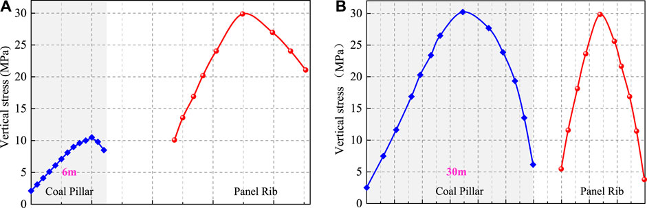
FIGURE 1. Vertical stress redistribution characterization of narrow and wide coal pillar. (A) Narrow coal pillar; (B) Wide coal pillar.
With the construction of large-scale intelligent mines, the double-roadway layout system will be chosen for more working faces. The research on controlling gob-side entry retaining roadways, gob-side entry driving roadways and rock surrounding the roadways has achieved many results, while there is less research on controlling of stability of the coal pillar and its supporting structures in the double-roadway layout system under the disturbance of roadway driving, working face mining, and repeated mining (Qi and Fourie, 2019; Zhang et al., 2020b; Meng et al., 2020; Chen et al., 2021a; Chen et al., 2021b). Wu et al. (2019c) proposed the strengthening effect of high-intensity support and grouting on coal pillars in mining roadways. Yao et al. (2020) discussed the impact of anchor cables in the advancing supporting area on mining support stress resistance. Li et al. (2014) presented a support form with a single hydraulic prop and I-beam support in the region impacted by the mining of the roadways driving head and working face. These studies considered the influence of dynamic pressure disturbance factors on the supporting structure instead of making a detailed study on the dynamic influence of the coal pillar and supporting structure, that is, the “small structure” under the disturbance condition of the double-roadway layout system. Nevertheless, there is almost no systematic research on the variation evolution of coal pillar stability under the whole disturbance process of the double-roadway layout system, which is the motivation of this paper.
Combining the previous research foundations of roof structure, lateral support stress for working face mining, and repeated mining disturbances stress law, and starting from coal pillar and supporting structures, this paper analyzes the influence law of the “small structure” of coal pillar and supporting bodies with different support intensities under the condition of repeated mining disturbance with a field investigation, numerical model construction, rock mechanics parameters input and calibration, and global model validation. The numerical simulation reproduces the whole process of the destruction of the “small structure” under repeated mining disturbances. Finally, the key technical parameters for narrow coal pillars under repeated mining disturbances is proposed. This numerical simulation reproduces the research method of stability control of the coal pillar and its supporting structure, promoting to an extent the development of the double-roadway layout system in China.
Therefore, the main objectives of this paper are:
- Developing a numerical model based on the geological conditions of the case, as well as proposing model parameter calibration and validation methods.
- The stability of coal pillars and their supporting structures under the face of repeated mining disturbance.
- The stability control strategies of “small structure” in the double-roadway system.
Case Study Site
Conditions of the Double-Roadway Layout System and Rock Strata
This object of study is the Gaohe Coal Mine, located in Changzhi City, Shanxi Province, China (Figure 2A); the current main coal seam is No. 3, with a thickness of 6.0 m and an average overburden depth of 600 m, and is mined using the consecutive single-wing mining method. The double-roadway layout means are adopted for the working face in Mining Area I in the western wing. The main research objects of this article are the W1308 headgate and W1309 tailgate. The double-roadway layout system involves driving along the roof strata of the coal seam, with a 7 m-wide coal pillar left in the middle. The cross-section of the W1308 headgate and W1309 tailgate is 5.0 m wide and 4.0 m in length. The three working faces of W1308, W1309, and W1310 are ceased and waiting for layout currently in the Mining Area W1 in the western wing, of which the working width of the working face W1308 is 180 m, with a length of 1,600 m (Figure 2B). The roof is composed of fine sandstone, mudstone, and medium sandstone in sequence. The floor plate is composed of mudstone, fine sandstone, and medium sandstone in sequence (Figure 2C).
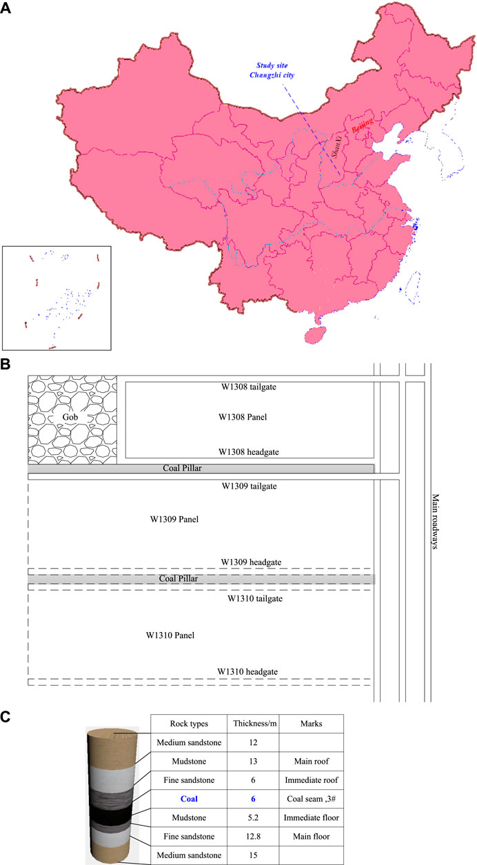
FIGURE 2. The geographical location and panel arrangement of the study site. (A) The location of the study site; (B) The panel and roadway layout of the study site; (C) The generalized stratigraphic column of the study site.
Coal Pillar Support Parameters of the Double-Roadway Layout System
The width of the coal pillar between the W1308 headgate and W1309 tailgate is 7.0 m and is driven along the roof. Figure 3 illustrates the roadways and coal pillar support parameters. Left-handed, non-longitudinal threaded steel bolts with a 22 mm diameter and a length of 2,400 mm were adopted for roof rock bolt support, with bolt spacing of 900 mm and each row of bolts spaced 800 mm apart, and six rock bolts per row. The roof rock bolts were perpendicular to the roof of the roadway, and were matched with square pallets and spherical anti-friction washers. The length, width, and height of the bolt plates were 150, 150, and 10 mm respectively, and the central aperture was 1.5–2.0 mm larger than the diameter of the bolt rod. CKb2335 and a K2360 resin anchoring agent were adopted for anchoring, with CKb2335 in the front, and K2360 at the rear. Mine anchor cables of a diameter and length of 17.8 and 6,300 mm respectively were used for roof anchor cable support. The spacing and row spacing of anchor cables were 1,600 mm and 800 mm respectively, with three anchor cables in each row, matched with locks and square plate. The length, width, and height of the anchor cable plates were respectively 300, 300, and 16 mm. One CKb2335 and two K2360 resin anchoring agents were adopted for anchoring the anchor cable, with CKb2335 in the front and K2360 in the back. The roof was laid with reinforced ladder beams made of 10# square mesh and 16# round steel. The length and width of square mesh were 5,200 mm and 1,100 mm respectively. Meshes must be overlapped with no less than 100 mm and must be tied firmly with barbed wire. The reinforced ladder beams used for the roof rock bolts were 4,700 mm long and 60 mm wide, while the roof anchor cables were 3,400 mm long and 60 mm wide.
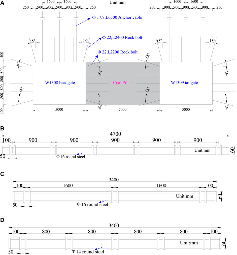
FIGURE 3. The width of the coal pillar and the specifications of the roadway support in the double-roadways layout system. (A) W1308 headgate and W1309 tailgate rock bolts and anchor cables support sectional drawing; (B) The dimensions of reinforced ladder beam of roof rock bolts; (C) The dimensions of reinforced ladder beam of roof anchor cables; (D) The dimensions of reinforced ladder beams of two ribs rock bolts.
Two ribs were supported using left-handed non-longitudinal rebar rock bolts with a size and length of 22 and 2,200 mm, respectively. The row spacing was 800 mm, and the bolt spacing was 800 mm. Four rock bolts were installed in each row, and the rock bolts on ribs were perpendicular to the rib, while the rock bolts at the rib corners were set at a 15° incline. Bolts were equipped with a square plate anti-friction washer, and a spherical washer. The length, width, and thickness of the rock bolt plates were 150, 150, and 10 mm respectively. The rock bolts were anchored with a CKb2335 and a K2360 resin anchoring agent, with CKb2335 in front and K2360 at back. The two ribs were laid with reinforced ladder beams made of 10# square mesh and 14# round steel. The square mesh was 4,200 mm long and 1,000 mm wide, while the two ribs of the reinforced ladder beam were 3,400 and 60 mm long and wide, respectively.
Numerical Model of Double-Roadway System
Simulation Model Setup
Gao and Stead (2014) introduced the “UDEC Trigon” logic to represent brittle rock fracture. The rock mass is described as a set of triangular blocks linked by internal contact to imitate brittleness material in the triangle procedure. These zones cannot fail if each triangular block is made of an elastic material and is split into triangular finite-difference areas. Shear or tensile stress damage can only occur across the contact surface, and the strength of the contact surface defines the effectiveness of the model. The stress-displacement connection is considered to be linear and is governed by stiffness
Where
Toward normal contact, there is a maximum tensile strength,
The reaction in the shearing direction is governed by a constant shear stiffness,
Then
or else, if
Then
Where
Configuration of the Numerical Model
The two-dimensional UDEC model is used to describe the failure characteristics of the coal pillar and its supporting structure under the disturbance of repeated mining, as well as to develop different coal pillar and roadway support parameters (Figure 4). The model is 180 m wide and 70 m high. To enhance the computation efficiency of the model, only the area of interest, namely the W1308 headgate and W1309 tailgate, and the coal pillar range between them, are discretized using “UDEC Trigon” logic. The average size of the triangular blocks in the region of interest is 0.2 m, and a longer triangular block with a size of 0.5 m is used to represent the roof-to-floor rocks in the region of the two roadways and the coal pillar, and a narrow and long rectangular block is used to represent the coal seam and rock layers at the triangular block boundary.
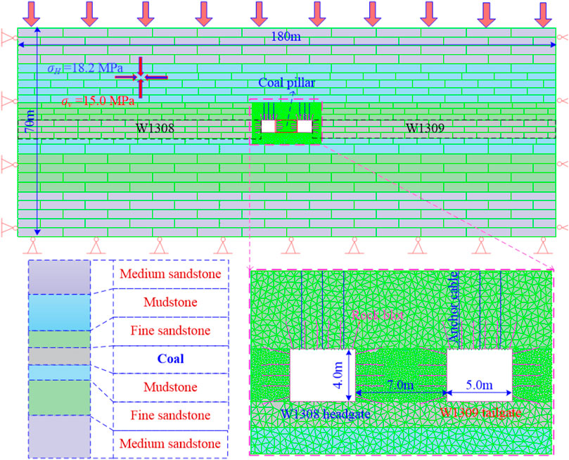
FIGURE 4. Numerical calculation model for stability analysis of coal pillar and its supporting structure under repeated mining disturbances.
Fixed displacements are conducted in the vertical and horizontal directions at the bottom and two sides of the model. According to the field stress test, the vertical stress is 15.0 MPa, the maximum principal stress is 18.2 MPa perpendicular to the axis of the roadway, and the minimum principal stress is 12.4 MPa parallel to the axis of the roadway. This original rock stress state is applied to the model, and a vertical stress of 15.0 MPa is applied to the upper boundary of the model to simulate the pressure of the overlying rock.
In general, the simulation calculation of the stability of the coal pillar and its supporting structure under the disturbance of repeated mining of the double-roadway layout system is mainly divided into four steps, as shown in Figure 5:
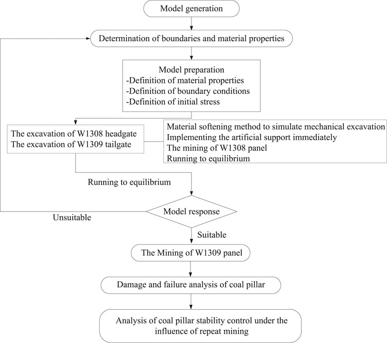
FIGURE 5. Flowchart of numerical modeling for studying coal pillar failures.
Step 1: Initial ground stress conditions are applied in the global model, to calculate the balance, and save it as a numerical model of the original rock stress balance.
Step 2: Excavation of the two roadways of the double roadway layout system, excavate the W1308 headgate and W1309 tailgate, and carry out bolt and cable support, calculate the balance, and save it as a numerical model after the roadways excavation.
Step 3: Mining simulation of the W1308 working face. It is a process of gradual mining by the coal mining machine for the excavation of the W1308 working face in the field. Therefore, segmented deletion of partial blocks is used for the mining simulation of the W1308 working face in the model to avoid discrepancy between the large dynamic loads and the site resulting in excessive errors in the simulation results. After the stepwise excavation, the balance is calculated and saved as a numerical model of the coal pillar disturbed by the mining at different excavation stages.
Step 4: W1309 working face mining simulation. The W1309 working face mining simulation method is the same as W1308 working face mining, the balance is calculated after distributed excavation, and it is saved as a numerical model of repeated mining disturbances in different excavation stages.
For the W1308 and W1309 working face mining simulation proposals: The excavation of the panels was recreated using a progressive excavation. Each step requires a 10 m advancing distance, 40,000 time steps were executed at each level to answer dynamic stress. (Gao et al., 2015).
Numerical Simulation Model Parameters Calibration
Laboratory-obtained rock characteristics should be modified into rock mass parameters. The RQD method is frequently used to estimate the deformation modulus of a rock mass. Supported by a large amount of on-site monitoring data, Zhang and Einstein (Zhang and Einstein, 2004) proposed the relationship Eq. 6 between RQD and
Where
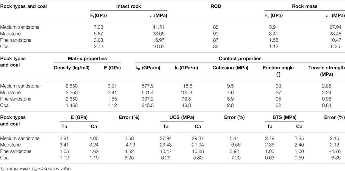
TABLE 1. Intact rock, rock mass, and mechanical properties.
These data’s rock mass properties parameters cannot be applied to the model directly, and the mechanic parameters of the contact surface and triangle utilized to represent the rock mass properties must be acquired by numerical calibration. Hence, UDEC Trigon logic calibration models were developed, which are the UCS test model with 2.0 m and a height of 4.0 m, and the Brazilian shear test model with a diameter of 2.0 m. The trial-and-error approach is used to calibrate the input parameters of the block and contact surface to fit the rock mass characteristics shown in Table 1; Figure 6 presents the calibration results for rock and coal (The term “Damage” shown in Figure 6 is introduced in Section Coal Pillar Failure Study Under the Original Support Scheme), as well as the micro-parameters in Table 1. Table 1 shows that the error between the UCS and E obtained by numerical simulation model and the results acquired by laboratory test is a little less than 10%. These parameters exactly match the rock mass properties in this research, indicating that the micro-mechanical parameters of coal and rock mass obtained in Table 1 are acceptable.

FIGURE 6. UDEC Trigon models calibration result for UCS testing. (A) The samples using for UDEC Trigon and laboratory testing; (B) The failure and cracking characteristics of UDEC Trigon and laboratory samples; (C) Stain-stress and damage curves of coal sample; (D) The strain-stress curves of three rock types of samples are acquired by the numerical model.
Roadway Excavation Method and Supporting Structure Units
In this section, the W1308 headgate and W1309 tailgate are excavated with a width and height of 5.0 and 4.0 m, respectively. The numerical simulation procedure simulates the excavation of the roadways by deleting blocks. Conversely, rapid excavation may result in an imbalanced model response, resulting in a dynamic stress path around the deleting border. This type of dynamic stress generally results in a more extensive damage region than desired around the excavation (Cai, 2008). The roadways are progressively and constantly mined by the heading machine in the field excavation, and the static stress path is developed by the roadway’s boundaries (Hazzard and Young, 2004; Yang and Fall, 2021). To reflect this more realistic mining impact, the material softening approach is used to simulate the mechanical excavation of the roadways. In this procedure, the Young’s modulus of the element in the excavation region deteriorates to zero in stages to represent the impact of progressive excavation. This procedure reduces the impact of transients on material failure and provides a more static resolution.
In the numerical simulation, a rock bolt element is made up of two structural nodes and one structural component. The structural components are elastic and plastic materials, as shown in Figure 7, which yield under tension and compression and can resist bending moments. The rock bolt element can realistically realize the normal shear and axial tension of the bolt. The components can be disconnected and separated at the nodes. Fracture of the rock bolt element is realized depending on the user-specified tensile failure strain thresholds (tfstrain). The following criteria were used to determine the failure of the rock bolt element:
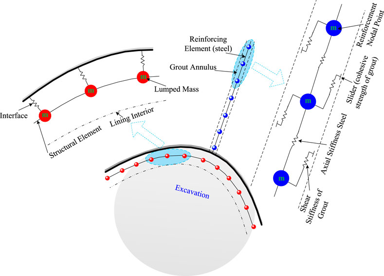
FIGURE 7. Schematic diagram of the realization of UDEC structural components of anchoring rock bolts, anchor cables, and reinforcing ladder beams (Inc., 2014; Qian et al., 2016).
If the sum tensile yield strain of every unit of the anchoring rod exceeds the artificially set tensile failure strain limit (tfstrain), the stress and bending moment of the anchoring rod member will instantly decrease to zero, and it can be considered that the rupture occurs at the point of the anchoring rod. The built-in “cable” component represents the anchor cables, while the built-in “liner” component represents the roof and two reinforcing ladder beams (Bai et al., 2016; Bai et al., 2017). Figure 7 shows the schematic diagram of the composition of the anchoring rock bolts, the anchor cables, and the structural elements (Inc., 2014). The details of the support unit are provided in Table 2 of this study.
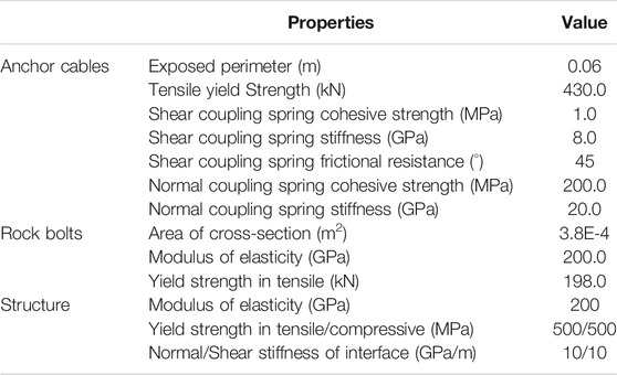
TABLE 2. The properties of supporting components used in the model.
Validation of Global Model Parameters
Deformation Analysis of W1309 Tailgate
The W1309 tailgate deformation and coal pillar loading characteristics are simulated numerically during the W1309 tailgate and W1308 headgate excavation periods, as well as throughout the W1308 mining stage. Figure 8 illustrates the difference between numerical simulation and on-site monitoring deformation data. The UDEC model shows the deformation features in the horizontal and vertical directions during double-roadway excavation and after first working face mining. Meanwhile, the numerical simulation also reproduces the failure mode of the roadway and coal pillar. From the results of the numerical simulation, the maximum value of horizontal convergence and vertical convergence of W1309 tailgate after double-roadway driveling are 200, 180 mm, respectively. After the first working face mining is completed, the maximum value of horizontal convergence and vertical convergence of the W1309 tailgate increases to 650 and 530 mm, respectively. The results of numerical calculations match those of on-site monitoring, demonstrating the validity of the UDEC model and the mechanical properties of the rock mass utilized in this research.
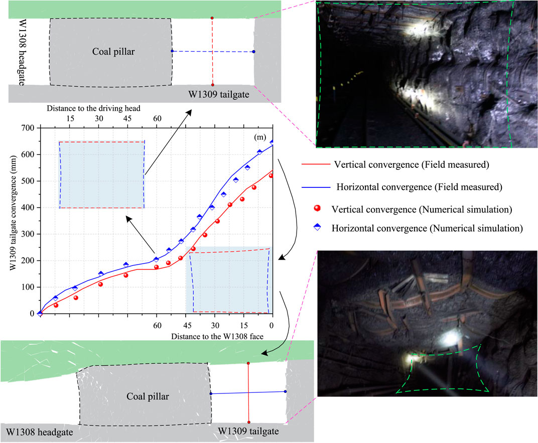
FIGURE 8. The simulation and on-site results of W1309 tailgate deformation during the driving of W1309 tailgate and W1308 headgate, as well as W1308 working face mining.
The Development of Vertical Stress on the Roadways’ Two Wall Sides
After excavating one side of the working face of the UDEC model established in part of this paper, the vertical stress features of the coal body on both sides of the roadway are monitored. The specific results are shown in Figure 9A. By comparing the distribution features of vertical stress on both sides of the roadway in the references (Zhang et al., 2017; Zhang et al., 2018; Feng et al., 2019b; Xia et al., 2021), as shown in Figure 9B, the rationality of the input parameters of the numerical calculation model is corrected. Due to the affection of the factors such as different burial depths, different supporting conditions, and different coal intensity in the references (Zhang et al., 2017; Zhang et al., 2018; Feng et al., 2019b; Xia et al., 2021), the stress on both sides of the roadway is converted into a stress concentration factor for better comparative analysis. The numerical modeling result indicates that the integrated coal side wall supports most of the pressure, as shown in Figures 9A,B. The vertical stress concentration factor in the integrated coal body on the side of the roadway is between 3.0 and 4.0. Under the action of lateral support stress, the coal pillar is in a plastic bearing state (Liu et al., 2020b), and the vertical stress concentration factor in the coal pillar is between 0.5 and 0.9, which are all less than the original rock pressure. The peak internal stress of the coal pillar appears at the center of the coal pillar, and the peak internal stress of the integrated coal appears at a location away from the roadways.
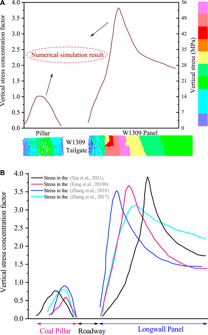
FIGURE 9. Comparison of vertical stress distribution features after the working face mining. (A) The law of vertical stress evolution of the roadways is calculated by the numerical simulation model; (B) The vertical stress concentration factor of the roadways in the references (Zhang et al., 2017; Zhang et al., 2018; Feng et al., 2019b; Xia et al., 2021).
Figures 9A,B shows that after the working face mining in a double-roadway layout system, the load in the coal pillar reaches its ultimate strength, and the vertical stress is lower than the in-situ stress, due to the combined activity of the lateral and advanced supporting pressure. By comparing the coal pillar of gob-side entry driving and double-roadway layout, as well as the vertical stress in integrated coal in the references (Zhang et al., 2017; Zhang et al., 2018; Feng et al., 2019b; Xia et al., 2021), the numerical model’s logic is proved. Meanwhile, it shows that when the coal pillar transitions from the elastic state to the plastic state, the roadways are prone to large deformation and damage, so it is necessary to strengthen the supporting intensity of the coal pillar. In general, it is feasible to simulate the control effect of different supporting intensities upon the roadway and coal pillar through the above input global parameters.
Study on the Stability of the Coal Pillar and its Supporting Structure
Coal Pillar Failure Study Under the Original Support Scheme
The Fish function has been used to measure the sum length of the cracks in the coal pillar, as well as the lengths of shear and tensile cracks induced by stress disturbances during excavation, first working face mining, then repeated mining, to obtain the failure characteristics of the coal pillar of the double-roadway layout system under the original support scheme. The damage parameters are proposed according to the standard of Gao and Stead (2014):
Where,
The changes in coal pillar damage parameters during double roadway tunneling (Stage 1), first working face mining (Stage 2), and repeated mining disturbance (Stage 3) are shown in Figure 10A. During double roadway driving (Stage 1), the damage parameter in the coal pillar increased slowly from 0 to about 20%, the damage parameter in the coal pillar increased from 20% to about 55% during the first working face mining (Stage 2), and the damage parameter in the coal pillar increased from 55% to around 90% during the repeated mining disturbance period (Stage 3).
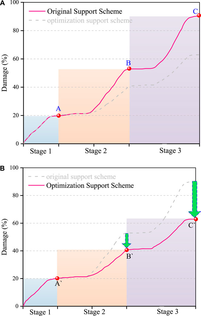
FIGURE 10. The damage change law of coal pillar at different stages. (A) original support scheme; (B) reinforced support scheme.
Analysis of Coal Pillar Failure Features Under Reinforced Support
It can be seen from the analysis in section Coal Pillar Failure Study Under the Original Support Scheme that under the original support conditions, when the first working face is mining at a long distance from the heading face, the extent of damage in the coal pillar does not change much compared with the tunneling period; but when completely experiencing the impact of first working face mining, the damage of the coal pillar increased to 55% under the original support scheme. When affected by the repeat mining disturbance, the final coal pillar was almost in a broken state, and the W1309 tailgate was seriously deformed, which could not meet the requirements for safe use. Therefore, a reinforced support plan is proposed in this part, and the main reinforced support parameters are as follows:
In the original support plan, the length of the bolts of the coal pillar sidewall was increased from 2,200 to 2,400 mm, and the pre-tightening force of the bolts was increased from 180 to 300 Nm. At the same time, two bolts with a length of 7,300 mm and a diameter of 7,300 mm were installed in the middle of the coal pillar. The tension pre-tightening force of the anchor cable is 200 kN. The model is recalculated according to the calculation process of the numerical model in 3.1, and the failure features of the coal pillar under the condition of reinforced support are obtained as shown in Figure 10B.
It can be seen from Figure 10B that after the reinforcement support conditions are adopted, the extent of damage in the coal pillar has not changed much compared with the original support scheme in stage 1. During stage 2, namely the first working face mining, with the gradual increase of the degree of mining influence, the damage in the coal pillar gradually became serious, but compared with the original support scheme, the final damage degree is reduced by about 15%; in the reinforcement support scheme for the stage 3, the repeated mining disturbance stage, the damage degree in the coal pillar is significantly reduced, and the reduction even reaches an astonishing 27%. Currently, the coal pillar is in the plastic bearing state and still has the features of isolation bearing.
Control Mechanism for the Stability of Coal Pillara and Roadways Under the Disturbance of Repeated Mining
From the previous analysis, we can see that there is a significant difference between the strength of reinforced support and conventional support in controlling the damage degree of a coal pillar, especially in the disturbance stage of repeated mining; the degree of damage to the coal pillar is significantly lower, and the supporting intensity is significantly reduced. The internal mechanism is mainly because the reinforcement support during the double roadway excavation can effectively limit the expansion and extension of the initial fissures inside the coal pillar under the disturbance of a dynamic load. It can be seen from Figure 11 that after the reinforcement support scheme is adopted, the damage extent in the coal pillar is not high after the first working face mining is completed, and there is a partially complete core bearing area inside the coal pillar; while during the disturbance period of repeated mining, the slipping, stretch, and shear occur to the internal fissures of the coal pillar, but under the restriction of high pre-tightening force bolts and high pre-tightening forces on the anchor cables. In the end, the large-scale destruction of the internal crack of the coal pillar did not occur, and in the middle of the coal pillar there existed a region defined as “Lower damage”, which is expected from the literature (Gao et al., 2015; Wu et al., 2019b; Wu et al., 2019c; Fan et al., 2019; Li et al., 2021). The damage is calculated by an Eq. 9, and “Lower damage” is defined as a region where the value is below 35%. Therefore, it shows that the initial support of the coal pillar and roadway has a significant effect in the double roadway layout system, which ensures the primary stability of the coal pillar and effectively limits the damage caused by disturbance of the repeated mining upon the coal pillar.
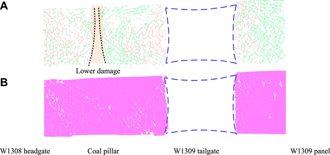
FIGURE 11. The failure rule of coal pillar and W1309 tailgate during repeated mining disturbance after reinforced support. (A) Crack features in coal pillar; (B) Failure model of coal pillar and roadways.
Discussion and Stability Control of Coal Pillar
Key Technical Parameters of Coal Pillar in the Double Roadway Layout System
Based on the above research, we proposed a double-roadway layout coal pillar stability control strategy under the disturbance of repeated mining. As shown in Figure 12A, it is mainly divided into two aspects: one is to improve the overall plastic bearing capacity of the coal pillar, and the other is to limit the expansion of the surface and internal cracks of the coal pillar.
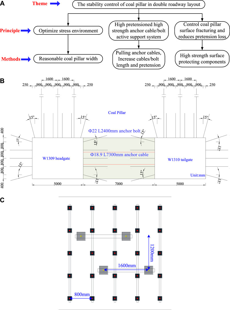
FIGURE 12. W1310 tailgate and the coal pillar support parameters. (A) Logic relation diagram of coal pillar stability control of double roadway layout; (B) The main view of the double roadway layout system support parameters; (C) The side view of the supporting parameters of coal pillar.
The proposed control strategy has been used in the double roadway layout system of the newly excavated W1309 headgate and W1310 tailgate. The main support parameters of W1310 tailgate control are shown in Figures 12B,C.
Field Application and Deformation of the Double-Roadway Layout System
Figure 13A shows the roadway deformation features of the W1310 tailgate during excavation, mining one side of the working face, and repeated mining disturbance. The monitoring results show that the deformation of the W1310 tailgate has been effectively controlled. During the excavation, the maximum value of the roof-to-floor convergence is 180 mm, and the maximum value of convergence of the rib-to-rib is 200 mm. During mining the first working face, the maximum value of roof-to-floor convergence is 420 mm, and the maximum value of convergence of the two sides is 500 mm. During the disturbance of repeated mining, the maximum value of roof-to-floor convergence is 620 mm, and the maximum value of rib-to-rib is 730 mm. Figure 13B shows the loads of rock bolts and anchor cables in the coal pillar during the repeated mining, within the influence range of the pressure, the loads of the anchor cables and rock bolts begin to increase. When the monitoring station is about 40 m away from the working face, the load of the anchor is increased to 140 kN, and the load of the anchor cable is increased to 195 kN. It shows that the load of the anchor cables and rock bolts increases rapidly and can bear the load in time, so the effect of controlling the deformation of the surrounding rock is better. Meanwhile, during the repeated mining disturbance, the imaging results of the borehole inside the coal pillar 10 m ahead of the working face are shown in Figure 13C. It can be seen from Figure 13C that at the position where the repeated mining disturbance is the most severe, there is still a certain complete area in the central part of the coal pillar, verifying the rationality of the control measures through the combination with the above deformation results.
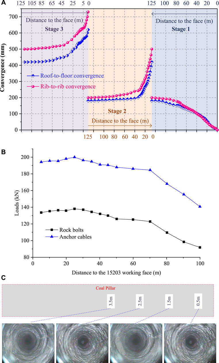
FIGURE 13. Deformation and crack features of the W1309 tailgate under the optimized support scheme. (A) Deformation of the newly excavated W1309 tailgate; (B) Loads of rock bolts and anchor cables in coal pillar during repeated mining; (C) Crack propagation features of coal pillar 10 m ahead of working face.
Conclusion
The supporting structures and coal pillar in the double-roadway layout system are impacted by driving, first working face mining, and repeated mining. The stability of coal pillar and supporting structures in a double-roadway layout system is investigated systematically using on-site and numerical simulation methods, the main conclusions are as follows:
1) A numerical calculation model of the double-roadway layout system was established, and the rock mechanics parameters input in the numerical model were systematically corrected based on the site geology and mining conditions. Meanwhile, the roadway excavation method and the simulation method of the support structure unit were analyzed. Finally, the global parameters are corrected to ensure the rationality of the numerical calculation model.
2) The stability of the coal pillar and its support structure under the disturbance of repeated mining was systematically studied through the corrected numerical calculation model, and the control effect of the reinforcement support on the damage extent of the coal pillar and its crack was analyzed. The combined support strategy of high pre-tightening force and high strength anchor cables and rock bolts with high rigidity surface protection members.
3) The proposed control key support strategy and technical parameters are applied to the newly excavated W1309 headgate and W1310 tailgate double roadway layout system. The on-site monitoring results show that after the optimized support parameters are adopted, the roof-to-floor convergence of the W1310 tailgate during the tunneling period, working face mining, repeated mining disturbance is 180, 420, and 620 mm respectively, and the rib-to-rib convergence is 200, 500, and 730 mm respectively, which verifies the control effect of the optimized support parameters on the coal pillar effect.
Further Research
The influence of the single hydraulic reinforcement support on the crack propagation and damage of the coal pillar and supporting structure should be considered, and the parameters of the rock bolts and anchor cables in the simulation model should be matched with the field data in detail in the future research.
The interaction and stability of the “large structure” of the “arc triangular block” formed by the lateral roof after panel mining as well as the “small structures” of the coal pillar and supporting structure are the focus of our future research.
Data Availability Statement
The original contributions presented in the study are included in the article/Supplementary Material, further inquiries can be directed to the corresponding author.
Author Contributions
Conceptualization, SL, YL, and JB; Methodology, XW; Formal analysis and investigation, SL and XW; Software, SL; Validation, JZ and GW; Writing-review and editing, SL, JB, XW, BW, GW, YL, and JZ.
Funding
This research was financially supported by the National Natural Science Foundation of China through contracts No. 52074239, and the National Key Research and Development Program of China through contracts No. 2020YFB1314200.
Conflict of Interest
The authors declare that the research was conducted in the absence of any commercial or financial relationships that could be construed as a potential conflict of interest.
Publisher’s Note
All claims expressed in this article are solely those of the authors and do not necessarily represent those of their affiliated organizations, or those of the publisher, the editors and the reviewers. Any product that may be evaluated in this article, or claim that may be made by its manufacturer, is not guaranteed or endorsed by the publisher.
Acknowledgments
The authors thank Gaohe coal mine for their support during the fieldwork.
References
Bai, Q.-S., Tu, S.-H., Zhang, C., and Zhu, D. (2016). Discrete Element Modeling of Progressive Failure in a Wide Coal Roadway From Water-Rich Roofs. Int. J. Coal Geology. 167, 215–229. doi:10.1016/j.coal.2016.10.010
Bai, Q., and Tu, S. (2019). A General Review on Longwall Mining-Induced Fractures in Near-Face Regions. Geofluids., 2019. doi:10.1155/2019/3089292
Bai, Q., and Tu, S. (2020). Numerical Observations of the Failure of a Laminated and Jointed Roof and the Effective of Different Support Schemes: a Case Study. Environ. Earth Sci. 79, 202. doi:10.1007/s12665-020-08935-2
Bai, Q., Tu, S., Wang, F., and Zhang, C. (2017). Field and Numerical Investigations of Gateroad System Failure Induced by Hard Roofs in a Longwall Top Coal Caving Face. Int. J. Coal Geology. 173, 176–199. doi:10.1016/j.coal.2017.02.015
Cai, M. (2008). Influence of Stress Path on Tunnel Excavation Response - Numerical Tool Selection and Modeling Strategy. Tunnelling Underground Space Technology. 23, 618–628. doi:10.1016/j.tust.2007.11.005
Chen, J., Liu, P., Zhao, H., Zhang, C., and Zhang, J. (2021a). Analytical Studying the Axial Performance of Fully Encapsulated Rock Bolts. Eng. Fail. Anal. 128, 105580. doi:10.1016/j.engfailanal.2021.105580
Chen, J., Zhao, H., He, F., Zhang, J., and Tao, K. (2021b). Studying the Performance of Fully Encapsulated Rock Bolts With Modified Structural Elements. Int. J. Coal Sci. Technol. 8, 64–76. doi:10.1007/s40789-020-00388-z
Fan, J., Jiang, D., Liu, W., Wu, F., Chen, J., and Daemen, J. (2019). Discontinuous Fatigue of Salt Rock With Low-Stress Intervals. Int. J. Rock Mech. Mining Sci. 115, 77–86. doi:10.1016/j.ijrmms.2019.01.013
Fan, J., Liu, W., Jiang, D., Chen, J., Tiedeu, W. N., and Daemen, J. J. K. (2020a). Time Interval Effect in Triaxial Discontinuous Cyclic Compression Tests and Simulations for the Residual Stress in Rock Salt. Rock Mech. Rock Eng. 53, 4061–4076. doi:10.1007/s00603-020-02150-y
Fan, J., Xie, H., Chen, J., Jiang, D., Li, C., Ngaha Tiedeu, W., et al. (2020b). Preliminary Feasibility Analysis of a Hybrid Pumped-Hydro Energy Storage System Using Abandoned Coal Mine Goafs. Appl. Energ. 258, 114007. doi:10.1016/j.apenergy.2019.114007
Feng, G., Wang, P., and Chugh, Y. P. (2019a). Stability of Gate Roads Next to an Irregular Yield Pillar: A Case Study. Rock Mech. Rock Eng. 52, 2741–2760. doi:10.1007/s00603-018-1533-y
Feng, X. W., Zhang, N., Xue, F., and Xie, Z. Z. (2019b). Practices, Experience, and Lessons Learned Based on Field Observations of Support Failures in Some Chinese Coal Mines. Int. J. Rock Mech. Mining Sci. 123, 104097. doi:10.1016/j.ijrmms.2019.104097
Feng, G., and Wang, P. (2020). Stress Environment of Entry Driven along Gob-Side Through Numerical Simulation Incorporating the Angle of Break. Int. J. Mining Sci. Technology. 30, 189–196. doi:10.1016/j.ijmst.2019.03.003
Galvin, J. M. (2006). “Considerations Associated with the Application of the Unsw and Other Pillar Design Formulae,” in Proceedings of the 41st U.S. Rock Mechanics Symposium - ARMA's Golden Rocks 2006 - 50 Years of Rock Mechanics.
Gao, F. Q., and Stead, D. (2014). The Application of a Modified Voronoi Logic to Brittle Fracture Modelling at the Laboratory and Field Scale. Int. J. Rock Mech. Mining Sci. 68, 1–14. doi:10.1016/j.ijrmms.2014.02.003
Gao, F., Stead, D., and Kang, H. (2014). Simulation of Roof Shear Failure in Coal Mine Roadways Using an Innovative UDEC Trigon Approach. Comput. Geotechnics. 61, 33–41. doi:10.1016/j.compgeo.2014.04.009
Gao, F., Stead, D., and Kang, H. (2015). Numerical Simulation of Squeezing Failure in a Coal Mine Roadway Due to Mining-Induced Stresses. Rock Mech. Rock Eng. 48, 1635–1645. doi:10.1007/s00603-014-0653-2
Hazzard, J. F., and Young, R. P. (2004). Dynamic Modelling of Induced Seismicity. Int. J. Rock Mech. Mining Sci. 41, 1365–1376. doi:10.1016/j.ijrmms.2004.09.005
Hou, C. J., and Li, X. H. (2001). Stability Principle of Big and Small Structures of Rock Surrounding Roadway Driven along Goaf in Fully Mechanized Top Coal Caving Face. Meitan Xuebao/Journal China Coal Soc. 26, 1. doi:10.3321/j.issn:0253-9993.2001.01.001
Inc, I. C. G. (2014). UDEC (Universal Distinct Element Code). Version 6.0. Minneapolis, MN, USA.: Itasca Office.
Jiang, L., Zhang, P., Chen, L., Hao, Z., Sainoki, A., Mitri, H. S., et al. (2017). Numerical Approach for Goaf-Side Entry Layout and Yield Pillar Design in Fractured Ground Conditions. Rock Mech. Rock Eng. 50, 3049–3071. doi:10.1007/s00603-017-1277-0
Li, L., Zhang, A. B., and Zhang, C. L. (2014). Study on the Abutment Pressure and Advanced Support of Driving Roadway Along Goaf of Isolated Mining Face. Amr. 941-944, 2533–2538. doi:10.4028/www.scientific.net/amr.941-944.2533
Li, W., Bai, J., Peng, S., Wang, X., and Xu, Y. (2015). Numerical Modeling for Yield Pillar Design: A Case Study. Rock Mech. Rock Eng. 48, 305–318. doi:10.1007/s00603-013-0539-8
Li, X., Ju, M., Yao, Q., Zhou, J., and Chong, Z. (2016). Numerical Investigation of the Effect of the Location of Critical Rock Block Fracture on Crack Evolution in a Gob-Side Filling Wall. Rock Mech. Rock Eng. 49, 1041–1058. doi:10.1007/s00603-015-0783-1
Li, X., Wang, Y., Yang, S., Xiong, J., and Zhao, K. (2021). Research Progress in the Mining Technology of the Slowly Inclined, Thin to Medium Thick Phosphate Rock Transition from Open-Pit to Underground Mine. Appl. Mathematics Nonlinear Sci. 6, 319–334. doi:10.2478/amns.2021.2.00017
Liu, S., Bai, J., Wang, X., Wu, B., Wang, G., Li, Y., et al. (2021). Study on Dynamic Evolution of Roof Crack and Support Timing of Secondary Tunneling for Large Section Open-Off Cut in Deep Mines. Adv. Civil Eng. 2021. doi:10.1155/2021/9918470
Liu, S., Bai, J., Wang, X., Wu, B., and Wu, W. (2020a). Mechanisms of Floor Heave in Roadways Adjacent to a Goaf Caused by the Fracturing of a Competent Roof and Controlling Technology. Shock and Vibration. 2020. doi:10.1155/2020/5632943
Liu, W., Zhang, Z., Fan, J., Jiang, D., Li, Z., and Chen, J. (2020b). Research on Gas Leakage and Collapse in the Cavern Roof of Underground Natural Gas Storage in Thinly Bedded Salt Rocks. J. Energ. Storage. 31, 101669. doi:10.1016/j.est.2020.101669
Mark, C., and Agioutantis, Z. (2018). “Analysis of Coal Pillar Stability (ACPS): A New Generation of Pillar Design Software,” in Proceedings of the 37th International Conference on Ground Control in Mining, ICGCM 2018, 1–6.
Meng, N., Bai, J., Chen, Y., Wang, X., Wu, W., Wu, B., et al. (2020). Damage Evolution Mechanisms of Rock Induced by Blasting With the Aid of Empty-Hole Effect. Energies. 13, 756. doi:10.3390/en13030756
Mohamed, K., Van Dyke, M., Rashed, G., Sears, M. M., and Kimutis, R. (2021). Preliminary Rib Support Requirements for Solid Coal Ribs Using a Coal Pillar Rib Rating (CPRR). Int. J. Mining Sci. Technology. 31, 15–22. doi:10.1016/j.ijmst.2020.12.006
Prassetyo, S. H., Irnawan, M. A., Simangunsong, G. M., Wattimena, R. K., Arif, I., and Rai, M. A. (2019). New Coal Pillar Strength Formulae Considering the Effect of Interface Friction. Int. J. Rock Mech. Mining Sci. 123, 104102. doi:10.1016/j.ijrmms.2019.104102
Qi, C., and Fourie, A. (2019). Cemented Paste Backfill for Mineral Tailings Management: Review and Future Perspectives. Minerals Eng. 144, 106025. doi:10.1016/j.mineng.2019.106025
Qian, D., Zhang, N., Shimada, H., Wang, C., Sasaoka, T., and Zhang, N. (2016). Stability of Goaf-Side Entry Driving in 800-M-Deep Island Longwall Coal Face in Underground Coal Mine. Arabian J. Geosciences. 9, 1–28. doi:10.1007/s12517-015-2119-6
Rezaei, M., Hossaini, M. F., and Majdi, A. (2015). Development of a Time-Dependent Energy Model to Calculate the Mining-Induced Stress Over Gates and Pillars. J. Rock Mech. Geotechnical Eng. 7, 306–317. doi:10.1016/j.jrmge.2015.01.001
Salamon, M. D. G. (1971). Stability, Instability and Design of Pillar Workings. Author's Reply to Discussion by D. F. Coates* *. Int. J. Rock Mech. Min. Sci. 8, 641–642. Paper of the International Journal of Rock Mechanics and Mining Sciences and 9 (1972) 667-668. doi:10.1016/0148-9062(72)90018-6
Shen, W.-l., Bai, J.-b., Li, W.-f., and Wang, X.-y. (2018). Prediction of Relative Displacement for Entry Roof With Weak Plane Under the Effect of Mining Abutment Stress. Tunnelling Underground Space Technology. 71, 309–317. doi:10.1016/j.tust.2017.08.023
Shen, W.-l., Bai, J.-b., Wang, X.-y., and Yu, Y. (2016). Response and Control Technology for Entry Loaded by Mining Abutment Stress of a Thick Hard Roof. Int. J. Rock Mech. Mining Sci. 90, 26–34. doi:10.1016/j.ijrmms.2016.10.001
Shen, W., Shi, G., Wang, Y., Bai, J., Zhang, R., and Wang, X. (2021). Tomography of the Dynamic Stress Coefficient for Stress Wave Prediction in Sedimentary Rock Layer Under the Mining Additional Stress. Int. J. Mining Sci. Technology. 31, 653–663. doi:10.1016/j.ijmst.2021.04.003
Si, G., Durucan, S., Shi, J.-Q., Korre, A., and Cao, W. (2019). Parametric Analysis of Slotting Operation Induced Failure Zones to Stimulate Low Permeability Coal Seams. Rock Mech. Rock Eng. 52, 163–182. doi:10.1007/s00603-018-1579-x
Singh, M., and Seshagiri Rao, K. (2005). Empirical Methods to Estimate the Strength of Jointed Rock Masses. Eng. Geology. 77, 127–137. doi:10.1016/j.enggeo.2004.09.001
Wang, J., Wang, X., Zhang, Q., Song, Z., and Zhang, Y. (2021). Dynamic Prediction Model for Surface Settlement of Horizontal Salt Rock Energy Storage. Energy. 235, 121421. doi:10.1016/j.energy.2021.121421
Wang, M., Bai, J., Li, W., Wang, X., and Cao, S. (2015). Failure Mechanism and Control of Deep Gob-Side Entry. Arab J. Geosci. 8, 9117–9131. doi:10.1007/s12517-015-1904-6
Wu, W.-d., Bai, J.-b., Wang, X.-y., Zhu, Z.-j., and Yan, S. (2019a). Field Investigation of Fractures Evolution in Overlying Strata Caused by Extraction of the Jurassic and Carboniferous Coal Seams and its Application: Case Study. Int. J. Coal Geology. 208, 12–23. doi:10.1016/j.coal.2019.04.002
Wu, B., Wang, X., Bai, J., Wu, W., Zhu, X., and Li, G. (2019b). Study on Crack Evolution Mechanism of Roadside Backfill Body in Gob-Side Entry Retaining Based on UDEC Trigon Model. Rock Mech. Rock Eng. 52, 3385–3399. doi:10.1007/s00603-019-01789-6
Wu, W.-d., Bai, J.-b., Wang, X.-y., Yan, S., and Wu, S.-x. (2019c). Numerical Study of Failure Mechanisms and Control Techniques for a Gob-Side Yield Pillar in the Sijiazhuang Coal Mine, China. Rock Mech. Rock Eng. 52, 1231–1245. doi:10.1007/s00603-018-1654-3
Xia, Z., Yao, Q., Meng, G., Xu, Q., Tang, C., Zhu, L., et al. (2021). Numerical Study of Stability of Mining Roadways With 6.0-m Section Coal Pillars Under Influence of Repeated Mining. Int. J. Rock Mech. Mining Sci. 138, 104641. doi:10.1016/j.ijrmms.2021.104641
Xie, S. R., Pan, H., Chen, D. D., Zeng, J. C., Song, H. Z., Cheng, Q., et al. (2020). Stability Analysis of Integral Load-Bearing Structure of Surrounding Rock of Gob-Side Entry Retention With Flexible concrete Formwork. Tunnelling Underground Space Technology. 103, 103492. doi:10.1016/j.tust.2020.103492
Yan, S., Liu, T. X., Bai, J. B., and Wu, W. D. (2018). Key Parameters of Gob-Side Entry Retaining in A Gassy and Thin Coal Seam With Hard Roof. Processes. 6, 51. doi:10.3390/pr6050051
Yang, J., and Fall, M. (2021). Coupled Hydro-Mechanical Modelling of Dilatancy Controlled Gas Flow and Gas Induced Fracturing in Saturated Claystone. Int. J. Rock Mech. Mining Sci. 138, 104584. doi:10.1016/j.ijrmms.2020.104584
Yang, J., Fall, M., and Guo, G. (2020). A Three-Dimensional Hydro-Mechanical Model for Simulation of Dilatancy Controlled Gas Flow in Anisotropic Claystone. Rock Mech. Rock Eng. 53, 4091–4116. doi:10.1007/s00603-020-02152-w
Yao, Q., Wang, X., Xia, Z., Li, L., Zhu, L., and Li, X. (2020). Key Technology and Application of Active Forepoling for Longwall Coal Mining in Coal Mine. Caikuang Yu Anquan Gongcheng Xuebao/Journal Mining Saf. Eng. 37, 289–297. doi:10.13545/j.cnki.jmse.2020.02.009
Yu, Y., Bai, J., Wang, X., and Zhang, L. (2020). Control of the Surrounding Rock of a Goaf-Side Entry Driving Heading Mining Face. Sustainability (Switzerland). 12, 2623. doi:10.3390/su12072623
Zhang, G.-c., He, F.-l., Jia, H.-g., and Lai, Y.-h. (2017). Analysis of Gateroad Stability in Relation to Yield Pillar Size: A Case Study. Rock Mech. Rock Eng. 50, 1263–1278. doi:10.1007/s00603-016-1155-1
Zhang, G., Liang, S., Tan, Y., Xie, F., Chen, S., and Jia, H. (2018). Numerical Modeling for Longwall Pillar Design: A Case Study from a Typical Longwall Panel in China. J. Geophys. Eng. 15, 121–134. doi:10.1088/1742-2140/aa9ca4
Zhang, L., and Einstein, H. H. (2004). Using RQD to Estimate the Deformation Modulus of Rock Masses. Int. J. Rock Mech. Mining Sci. 41, 337–341. doi:10.1016/s1365-1609(03)00100-x
Zhang, X., Liu, W., Jiang, D., Qiao, W., Liu, E., Zhang, N., et al. (2021a). Investigation on the Influences of Interlayer Contents on Stability and Usability of Energy Storage Caverns in Bedded Rock Salt. Energy. 231, 120968. doi:10.1016/j.energy.2021.120968
Zhang, Z., Deng, M., Bai, J., Yan, S., and Yu, X. (2021b). Stability Control of Gob-Side Entry Retained Under the Gob With Close Distance Coal Seams. Int. J. Mining Sci. Technology. 31, 321–332. doi:10.1016/j.ijmst.2020.11.002
Zhang, Z., Deng, M., Bai, J., Yu, X., Wu, Q., and Jiang, L. (2020a). Strain Energy Evolution and Conversion Under Triaxial Unloading Confining Pressure Tests Due to Gob-Side Entry Retained. Int. J. Rock Mech. Mining Sci. 126, 104184. doi:10.1016/j.ijrmms.2019.104184
Keywords: repeated mining disturbance, numerical simulation, parameter calibration, control strategy, double-roadway layout
Citation: Liu S, Bai J, Wang X, Wang G, Wu B, Li Y and Zhao J (2021) Study on the Stability of Coal Pillars Under the Disturbance of Repeated Mining in a Double-Roadway Layout System. Front. Earth Sci. 9:754747. doi: 10.3389/feart.2021.754747
Received: 06 August 2021; Accepted: 27 September 2021;
Published: 14 October 2021.
Edited by:
Jinyang Fan, Chongqing University, ChinaReviewed by:
Qiuhong Wu, Hunan University of Science and Technology, ChinaSijiang Wei, Henan Polytechnic University, China
Copyright © 2021 Liu, Bai, Wang, Wang, Wu, Li and Zhao. This is an open-access article distributed under the terms of the Creative Commons Attribution License (CC BY). The use, distribution or reproduction in other forums is permitted, provided the original author(s) and the copyright owner(s) are credited and that the original publication in this journal is cited, in accordance with accepted academic practice. No use, distribution or reproduction is permitted which does not comply with these terms.
*Correspondence: Jianbiao Bai, YmFpamlhbmJpYW9AY3VtdC5lZHUuY24=