 Wei Zhipeng
 Wang Jinwei
 Liu Rumin
 Wang Tao
 Han Guannan
95% of researchers rate our articles as excellent or good
Learn more about the work of our research integrity team to safeguard the quality of each article we publish.
Find out more
METHODS article
Front. Earth Sci. , 19 November 2021
Sec. Economic Geology
Volume 9 - 2021 | https://doi.org/10.3389/feart.2021.730080
This article is part of the Research Topic New Advances in Geology and Engineering Technology of Unconventional Oil and Gas View all 24 articles
For economic and efficient development of extremely high-condensate shale gas reservoirs, a numerical model of segmental multicluster fractured horizontal well was established considering the effect of condensate and desorption, and the optimization of fracturing segments, fracturing clusters, half-length of main fracture, fracture permeability, fracture mesh density, and fracture distribution patterns were studied. It is indicated that the horizontal well whose design length is 2,700 m performs best when it has 43 fracturing segments with three clusters in each segment and the fracture permeability is 300 mD. The production capacity of horizontal wells is positively linearly correlated with the half-length of fractures. Increasing fracture half-length would be an effective way to produce condensate oil near wellbore. An effective fractured area can be constructed to remarkably improve productivity when the half-length of the fracture is 50 m and the number of secondary fractures is four in each segment. On the basis of reasonable fracture parameters, the staggered type distribution pattern is beneficial to the efficient development of shale gas-condensate reservoirs because of its large reconstruction volume, far pressure wave, small fracture interference, and small precipitation range of condensate.
Extremely high-condensate shale gas reservoirs, whose content of condensate can be as much as 600 g/m3, undergo more sophisticated phase behavior compared with ordinary shale gas reservoirs, where issues such as low porosity, low permeability, adsorption, and desorption are investigated. Liquid phase would first precipitate and then reversely gasify during continuous isothermal depressurization (Ali et al., 1993).
This kind of gas reservoir is mainly distributed in North America. The exploration of this kind of liquid-rich shale condensate gas reservoir is still in initial stage. In recent years, scholars have carried out researches on different aspects (Behmanesh et al., 2013; Labed et al., 2015; Xu, 2016; Di et al., 2019; Guo et al., 2019; Qian et al., 2021; Zhi et al., 2021). Taylor et al. (2014) constructed an all-component dual-permeability model to simulate the flow after fracturing in the well group and studied the contribution of primary and secondary fracture systems to the production of liquid-rich shale gas reservoirs while ignoring the optimization of artificial fracture systems. Haghshenas et al. (2014) applied commercial numerical simulators to study the effects of factors such as recombination decomposition and absorption, pore structure and connectivity, fluid composition, and production conditions on the production of liquid-rich shale condensate gas reservoirs, without taking fracture systems into account. Jiang and Younis (2016) established a multicomponent model of complex fractured shale condensate gas reservoir and studied the productivity of CO2 huff and puff. Labed (2016) conducted a numerical study on the flow of condensate gas in shale matrix using a pore network model, revealing the flow characters of the condensate shale gas. Multicluster fracturing of horizontal well is an effective means to develop shale gas condensate gas reservoir. Complex fracture network is generated during hydraulic fracturing process, bringing with it multiscale flow of matrix, natural fracture, and artificial fracture. Current investigations on extremely high-condensate shale gas reservoirs hardly consider the complex fracture system brought by segmental multicluster fracturing on the productivity of shale gas. In this article, the flow behavior in complex fracture systems is investigated, with the effect of adsorption–desorption and condensation. A numerical model of segmental multicluster fractured horizontal well is established based on Duvernay shale gas formation. The impact of parameters, including the number of fracturing segments, number of clusters in each segment, the half-length and permeability of a fracture, the fracture mesh density, and the distribution pattern of fractures, on the productivity of shale gas is then investigated based on the model. An optimized set of parameters is proposed in order to maximize the productivity.
The effective thickness of the Duvernay shale reservoir in Simonette block of Western Canada Basin is 30 to 45 m, TOC is 2% to 6%, effective porosity is 3% to 6%, and permeability is 0.0001 to 0.0003 mD. The content of condensate of this block is 630 to 1,125 g/m3, which is an ultrahigh-condensate gas reservoir by the international standard. The formation pressure is 77,000 kPa, and temperature is 116°C, so the reservoir fluid in the original state is gaseous, making it an unsaturated condensate gas reservoir. The dew point pressure is 28,550 kPa, and the maximum liquid precipitation is 29.51% (Figure 1A). The Langmuir isothermal adsorption curve is shown in Figure 1B. The average content of brittle minerals such as quartz and feldspar reaches 53%. Natural and induced fractures are easily formed under the action of external forces. As a result, complex fracture network probably dominates the pore system here. Large-scale multistage fractured horizontal wells were the main methods to produce the shale gas. Reasonable fracturing parameters of horizontal Wells are not clear yet.
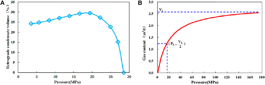
FIGURE 1. Volume fraction change of condensate oil in CVD experiment (A) and Langmuir equilibrium absorption curve (B).
At present, numerical simulation models of shale gas include dual-media model (Bustin et al., 2008; Ozkan et al., 2010), multimedia model (Wu et al., 2009), and equivalent-media model (Moridis et al., 2010). Among them, the dual-media model is the most widely used. The model assumes that shale is composed of two kinds of medium: matrix and fracture. Gas exists in shale in two forms: free state and adsorbed state, only free gas exists in fractures, and not only free gas exists in matrix, but also some gas is adsorbed on the matrix pore surface (Sun et al., 2012). The types of hydraulic fractures generated by staged fracturing vary from simple to complex, as shown in Figure 2. They are simple fractures, complex fractures, and fracture clusters (Fisher et al., 2004), among which the fracture cluster model is more consistent with the distribution of fracture network in the formation after hydraulic fracturing (Li et al., 2017; Li et al., 2018; Xie et al., 2020; Zhang et al., 2021a; Zhang et al., 2021b).
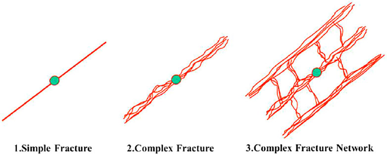
FIGURE 2. Types of hydraulic fracture.
It is a very effective method to treat complex fracture network into equivalent fracturing reconstruction volume (SRV). SRV is composed of artificial main fracture and inner and outer areas of fracturing reconstruction. The inner zone is a complex fracture network system formed by fracturing transformation, which is treated as dual medium. The outer zone is treated as a single pore medium because it is not subject to fracturing transformation. In each region, the fluid flow is treated as a linear flow (Wu et al., 2017). Other basic assumptions are as follows:
1) The reservoir is horizontally equal in thickness, the horizontal well is located in the center of the reservoir, and the fracture runs through the whole reservoir.
2) Consider the compressibility of oil and gas and ignore the compressibility of rock.
3) The adsorption and desorption of gas follows the Langmuir monolayer adsorption model. As the adsorption mechanism of condensate is not clear, it will not be considered separately.
4) The fluid is composed of oil and gas. The gas component exists only in the gas phase. The oil component can exist in both oil and gas phases at the same time. The content of dissolved condensate in the gas phase is characterized by Rv.
The outer region is the matrix region, and the adsorption and desorption of gas are described by Langmuir theory.
where VL is Langmuir volume (m3/m3); pL is Langmuir pressure (MPa); p is pressure (MPa); V is the gas adsorption capacity in unit volume rock (m3/m3).
Therefore, the gas phase seepage equation of the outer zone (subscript A indicates the outer zone) is as follows:
where k is absolute permeability (10-3 μm2); krg is relative permeability (decimal); μg is gas viscosity (mPa · s); Bg is volume factor (rm3/sm3); φ is porosity (decimal); Sg is gas saturation (decimal).
Initial condition:
Consider closed outer boundary conditions:
The inner boundary is coupled with the fractured medium in the inner region, and the inner boundary condition is
where pi is the original pressure (MPa); subscript f indicates the fracture in the inner area); y is the half-length of artificial fracture (m); ye is the outer boundary range (m).
The inner region is a dual medium, which is characterized by Kazemi model of unsteady mass transfer. Then, the gas phase seepage equation in the matrix of the inner area (expressed by subscript m) is:
Initial condition:
Consider closed outer boundary conditions:
The inner boundary is coupled with the fractured medium, and the inner boundary condition is:
Considering that there is gas exchange between the fractures in the outer area and the inner area. The gas phase flow from the outer area is as follows:
Considering the fluid supply from the inner matrix and the outer zone to the fracture medium in the inner zone, the gas-phase seepage equation in the fracture (expressed by subscript f) can be obtained as follows:
Initial condition:
Outer boundary condition:
The inner boundary is coupled with the artificial fracture, so the inner boundary condition is
Considering the fluid exchange from the inner fracture to the artificial fracture (expressed by subscript F), the gas phase exchange capacity can be obtained as follows:
Therefore, the gas phase seepage equation in artificial fracture can be obtained as follows:
Initial condition:
Outer boundary closure:
If the gas well is produced under constant bottom-hole pressure, the inner boundary condition is as follows:
Then, the gas production of the well can be obtained as follows:
GOR can be used to predict the output of oil phase. At the initial stage of production, the pressure has not spread to the reservoir boundary, and the gas oil ratio is constant, and GOR can be predicted with the data at the initial stage of production. When the pressure spreads to the boundary, GOR can be predicted by the material balance method.
Based on the DK-LS-LGR (dual permeability–logarithmic spacing change–local grid refinement) method of commercial numerical simulation software CMG, the complex fracture network generated by staged fracturing was characterized, and a mechanism model of staged multicluster fractured horizontal well in dual-media shale gas condensate reservoir considering the effects of condensate and desorption was established (Figure 3). A locally infilled double-permeability mesh with logarithmic spacing variation was used within the staged fracture zone to simulate the primary and secondary fractures generated by fracturing near the wellbore zone, whereas a common double-permeability mesh was used outside the zone to simulate the effects of natural fractures.
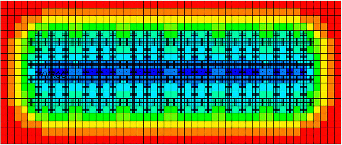
FIGURE 3. Fracture distribution diagram of segmental fractured horizontal well mechanism model.
Based on the implementation of a large number of microseismic monitoring in the target block, it is clear that the effective half-length of fracture in the segmental fractured horizontal well is 50 to 75 m (Figure 4). The historical matching process of the model shows that the fitting effect is the best when the half-length of the fracture is 50 m. The permeability of hydraulic fractures is high in the near-well zone and low in the far-well zone. The fractures in each fracture stage are described as the fracture model in Figure 5, and the fracture permeability is set to decrease along the half-length of the fracture from the near-well to the far-well to further describe the actual situation of fractures in the formation.
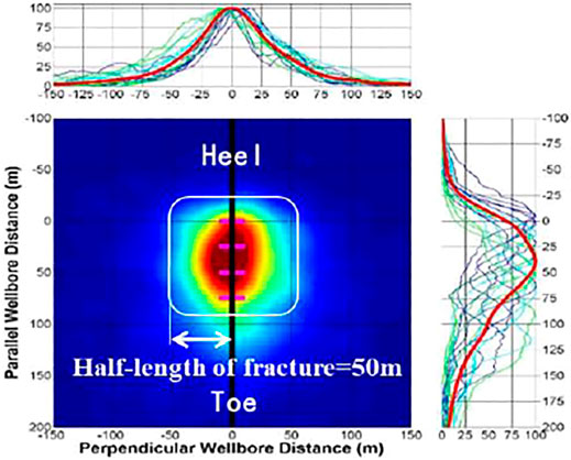
FIGURE 4. Microseismic interpretation map.
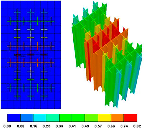
FIGURE 5. Permeability distribution of hydraulic fractures in fracturing segment.
WinProp module was used to process the PVT experimental data of the original well fluid, and the equation of state was fitted to generate the fluid model. Considering the influence of parameters such as fracture permeability, porosity, and water saturation decreasing along the half-length of fracture, the single-well history matching is carried out for bottom-hole pressure and daily oil and gas production, so as to make the model truly conform to the actual performance of gas reservoir. The fracture stress sensitivity is introduced into the simulation, and the fitting formula is as follows:
where Kmult is dimensionless permeability multiplication coefficient, and P is formation pressure (kPa). Fracture permeability will decrease with the decrease in formation pressure, which can further improve the fitting accuracy of bottom-hole pressure. During the model prediction, the half-length of fractures is set to be 50 m, with two to four clusters of fractures in each fracture stage, and the cluster spacing is 18 m. The production at constant pressure of 20,000 kPa was carried out under the combined action of condensate and desorption for 25 years.
The typically designed well length in ultrahigh condensate zone is 2,700 m. In order to develop shale condensate gas reservoir economically and efficiently, reasonable fracturing parameters of horizontal well should be determined. Based on the single-well model, the effects of the number of fracture stages, the number of clusters in the fracture stage, the half-length and permeability of the main fracture, the fracture network density, and the fracture distribution pattern on the development effect were studied.
By keeping the length of horizontal wells constant, the numerical simulation study was carried out on horizontal wells with different number of fracture stages including two cluster fractures, three cluster fractures, and four cluster fractures. The variation curves of accumulated gas and accumulated condensate under different number of fractures were obtained (Figure 6).
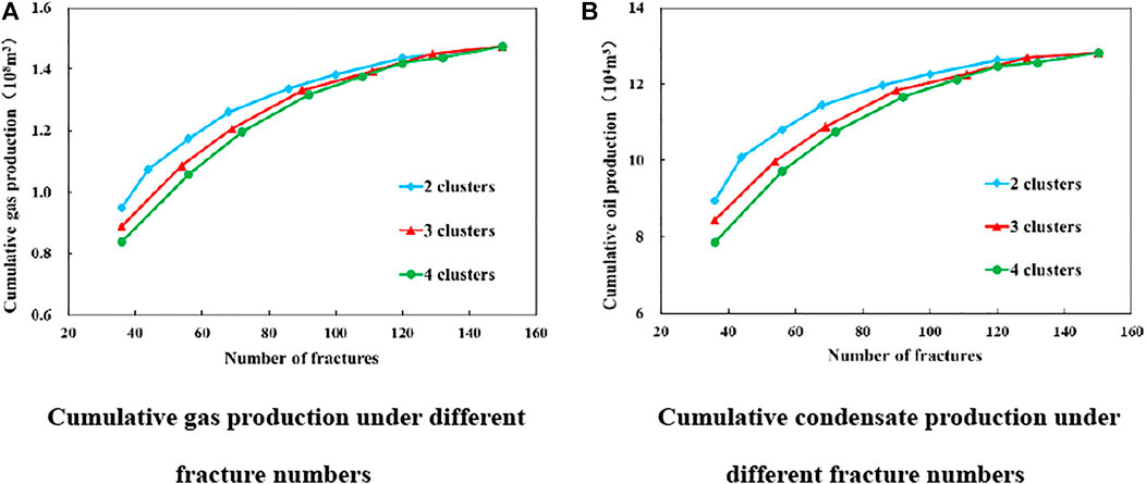
FIGURE 6. Cumulative gas and condensate production curves of different numbers of fractures.
It can be seen from Figure 6 that the number of fractures has a great influence on the amount of accumulated condensate oil and gas. When the number of fractures is small, the growth range of accumulated gas and accumulated condensate oil is large with the increase in the number of fractures, and the lower the number of clusters within the interval, the higher the accumulated oil production. This is because under the same number of fractures, the fewer clusters per stage, the more fracture stages, and the larger the transformation range, which is conducive to the communication of more natural fractures, so as to improve the seepage conditions and increase the production rate. When the total number of fractures reaches a certain number, the change of accumulated gas and accumulated condensate with the increase in fracture number is not significant, and the difference between different cluster numbers becomes small. This is due to the decrease in reservoir pressure during depletion development of shale gas reservoirs as production progresses. The more the number of fractures, the faster the formation pressure drops. On the one hand, it is advantageous to the adsorption of shale gas desorption, increasing the reservoir gas. On the other hand, when the pressure is lower than the dew point, the condensate oil precipitates, and two-phase flow begins to appear in the formation, which leads to the increase in seepage resistance, the decrease in gas and oil production speed, and the loss of a large amount of condensate oil in the formation. It is the contradiction between fracturing stimulation and fluid resistance reduction. At the same time, the increase in fracture number leads to the decrease in interval spacing, bringing with it the interfracture interference, which restrains the production of each fracture and the overall effect of fracturing stimulation. Because of the large number of fractures, the difference of fracture treatment range with different cluster numbers becomes smaller, so the difference of cumulative production becomes smaller too. The comparison shows that 129 fractures is the optimal value, corresponding to a reasonable number of fracturing stages of 43, with three clusters of fractures in each stage. In this way, the shale reservoir can be fully stimulated to significantly increase oil and gas production, and the cumbersome situation caused by too many fracturing stages due to the small number of clusters in a single stage can be avoided.
Artificial fracture half-length affects the control range of single horizontal well to some extent. Increasing the half-length can improve the contact area between fracture and reservoir. Based on the optimized number of fracturing stages and the number of clusters within the stages, the fracture half-lengths were set as 20, 50, 80, 110, and 140 m, and the relationship curve between the accumulated oil and gas volume and the fracture half-length was obtained through simulation (Figure 7A). As can be seen from the figure, horizontal well productivity basically goes positively linear with fracture half-length. For shale reservoirs with very poor permeability, increasing artificial main fracture half-length can significantly expand the scope of reservoir reconstruction, thus increasing gas well productivity. In the production process, there will be two phase zones and condensate accumulation around the fracture surface, which leads to the decrease in gas and liquid permeability and the decrease in production. As can be seen from the condensate saturation distribution diagram (Figure 7B) in the fracturing stage under different fracture half-lengths, as the fracture half-length increases, the condensate saturation in the fracturing stage gradually decreases, so the seepage resistance will decrease correspondingly and the flow state of the fluid will be significantly improved. It can be concluded that increasing the fracture half-length is an effective way to exploit the potential of condensate near the well. However, in the actual fracturing process, fracturing equipment cannot meet the construction requirements of excessively high fracture half-length, so the economic and technical constraints can be fully considered to optimize the economic and optimal main fracture half-length.
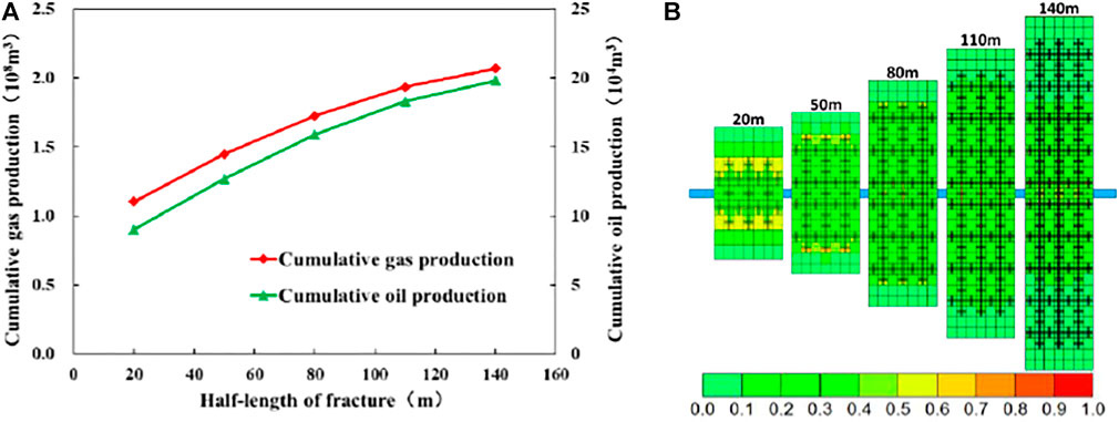
FIGURE 7. Cumulative condensate and gas production curves (A) and condensate saturation distribution of fracturing segment (B) under different half-length of fracture.
Domestic and foreign experience in the transformation of ultralow permeability reservoirs by staged fractured horizontal wells shows that such reservoirs do not require high conductivity of artificial fractures (Yin et al., 2014). Figure 8 shows the productivity prediction curves of horizontal Wells with different fracture permeability. The simulation results also confirm this view. Figure 9A shows that increasing the main fracture permeability has limited ability to improve the production status of shale condensate gas wells. When the main fracture permeability increases to a certain extent, the productivity of gas Wells does not increase significantly.
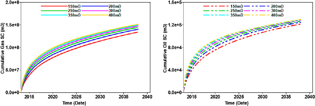
FIGURE 8. Productivity of segmental fractured horizontal well with different fracture permeability.
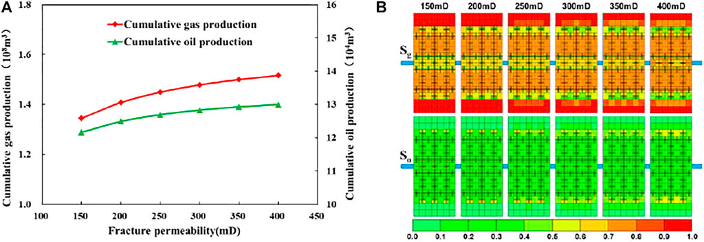
FIGURE 9. Cumulative condensate and gas production curves (A) and oil and gas saturation distribution of fracturing segment (B) under different fracture permeability.
The permeability of shale gas condensate reservoir is very poor, and the conductivity between the fractures and the surrounding reservoir after fracturing is an important factor restricting the productivity of horizontal wells. Insufficient fluid supply from unmodified reservoirs to artificial fractures restricts the high seepage capacity of artificial fractures. As can be seen from the oil–gas saturation distribution in Figure 9B, when the permeability of the main fracture increases to a certain extent, there is no significant effect on oil and gas stimulation. When the number and half-length of fractures remain unchanged, the pursuit of excessive seepage capacity will inevitably lead to the increase in the difficulty of construction and the increase in fracturing cost (Mao et al., 2020). Therefore, it is reasonable to set the main fracture permeability as 300 mD.
Fracture mesh density means the number of secondary fractures in each half-fracture. On the basis of the above fracture parameter optimization results, the half-length of the fracture in the model is set to be 50 m. Numerical simulations in which the number of secondary fractures in a single fracture stage is 0, 2, 4, 6, 8, and 10 are conducted, respectively, to simulate the development effect of staged fractured horizontal wells in shale condensate gas reservoir under different fracture network densities. It can be seen from the cumulative oil and gas volume curves of different numbers of secondary fractures (Figure 10A) that when the number of secondary fractures increases from 0 to 2, the cumulative oil and gas volume does not increase significantly. This is because there are few secondary fractures at this time, and no effective fracturing area has been formed. The amount of oil and gas production increased dramatically when the number of secondary fractures increases to 4. While the fracture mesh density continues to increase, oil and gas production increment is slow, which is due to the overlapping waste of transformation volume when fracture mesh density increases to a certain degree.
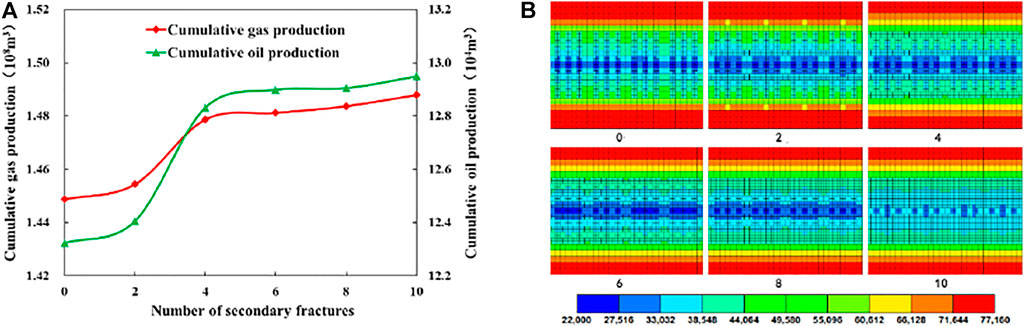
FIGURE 10. Cumulative condensate and gas production curves (A) and local pressure distribution map of horizontal wells (B) under different number of secondary fractures.
Figure 10B shows the local pressure distribution of staged fractured horizontal wells with different fracture network densities during 1 year of production. The analysis shows that when there are fewer than two secondary fractures, the fracture network density is small, the pressure wave propagation is slow, and the spread range is small. When the number of secondary fractures reaches four, the main fractures and secondary fractures are staggered and connected, forming a complex fracture network. The reservoir between fractures is fully reformed, the pressure swept area increases, the pressure drop range is wide, and the stimulation effect is significant. As the fracture network density continues to increase, the pressure swept area does not change significantly, so the stimulation effect is no longer obvious.
After optimizing the fracture parameters of segmented multicluster fractured horizontal wells, the effect of fracture distribution pattern on the productivity of shale gas condensate wells is further studied. In this case, a local horizontal well is fractured with six fractured sections, three clusters of fractures in each section, and main fracture permeability of 300 mD. Four fracture distribution patterns are designed (Figure 11) under the condition of maintaining the same total fracture length, which are of equal length type, staggered type, spindle type, and dumbbell type. Through simulation, the cumulative production figure (Figure 12) and the relationship curve between cumulative production and production time (Figure 13) were obtained under different fracture laying patterns.
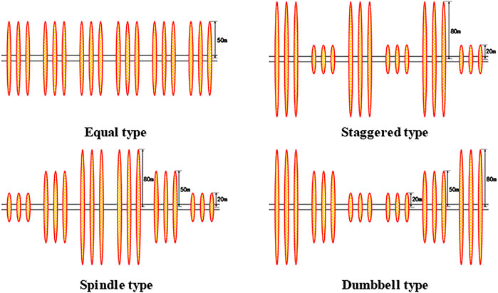
FIGURE 11. Different fracture laying patterns.
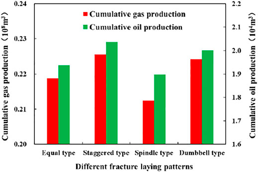
FIGURE 12. Cumulative condensate and gas production of different fracture laying patterns.
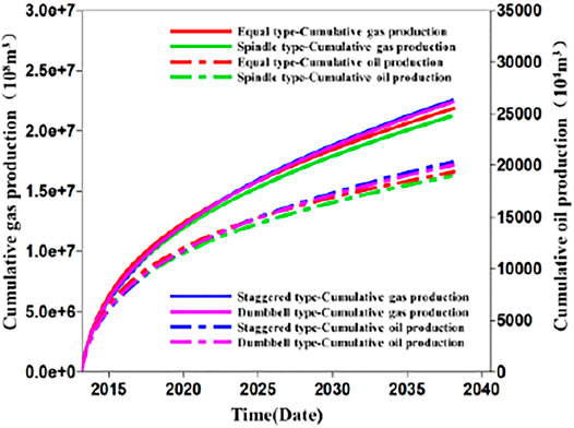
FIGURE 13. Cumulative condensate/gas–time curves of different fracture laying patterns.
It can be illustrated from Figure 12 that the total fracture length is the same, and the final production of different fracture distribution pattern is different. The cumulative oil and gas production of staggered pattern is significantly higher than that of the other three types. It can be demonstrated from Figure 13 that the initial outputs of the four fracture laying patterns are the same, and the production capacity of the staggered type in the middle and later stages of production is obviously different from the other three types. This is because in the early stages of production, production is largely controlled by artificial fractures. Because the total fracture length is the same, the oil and gas productions are the same. With the extension of production time, the influence of pressure spread and the interference between fractures on productivity is greater. As can be seen from the pressure distribution diagram (Figure 14) of horizontal wells with different distribution methods after 5 years of production, the staggered type has a higher productivity due to more long fractures, larger volume of transformation, and longer range of pressure spread. At the same time, there is little interference between long and short cross-fractures, avoiding large scale of low pressure zones, and condensate precipitating (Figure 15), which reduces the reservoir damage, thus effectively improving the fluid flow state of the reservoir and achieving better stimulation effect.
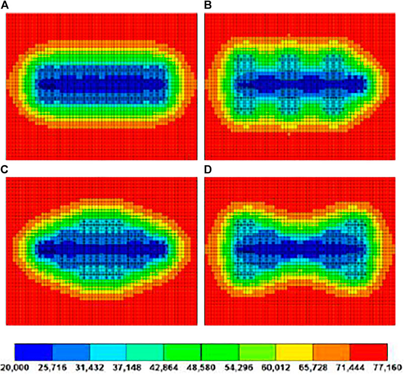
FIGURE 14. Pressure distribution map of horizontal wells with different fracture laying patterns.
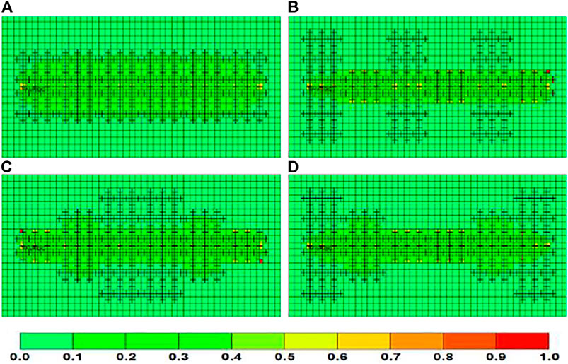
FIGURE 15. Oil saturation distribution map of horizontal wells with different fracture laying patterns.
A numerical model of segmental multicluster fractured horizontal wells is composed to discuss the flow of extremely rich gas condensate in complex fracture systems. The impact of factors including fracturing segments, fracturing clusters, half-length of main fracture, fracture permeability, fracture mesh density, and fracture distribution patterns on productivity were studied. The conclusions may provide meaningful support to the economic and efficient development of Duvernay gas-condensate shale reservoirs. However, some issues are still valuable to be further investigated and listed below.
1) The optimized fracture parameters are discussed via numerical simulation on the Duvernay formation, whereas those parameters have not yet been coupled with the field fracturing process. Whether the values of the parameters are applicable in the field practice needs to be further discussed.
2) In the optimization process, the parameters are discussed on the basis of other optimized values. Therefore, the interactions between parameters are not investigated. Further study could discuss the interaction between fracturing parameters by an orthogonal designed test.
3) The fracture patterns in this article are just in a theoretical way; the applicability of the fracture pattern should be discussed on the basis of field fracturing practice. The relationship between pump procedure and fracture patterns on the basis of stress interference is a significant issue.
For economic and efficient development of extremely high-condensate shale gas reservoirs, a numerical model of segmental multicluster fractured horizontal well was established considering the effect of condensate and desorption, and the optimization of fracturing segments, fracturing clusters, half-length of main fracture, fracture permeability, fracture mesh density, and fracture distribution patterns were studied. The results are as follows:
1) Based on the DK-LS-LGR method of CMG, the complex fracture network generated by staged fracturing is characterized with a single-well mechanism model of dual media staged multicluster fracturing horizontal well to simulate the multiscale flow of matrix, natural fractures, and artificial fractures in ultrahigh-condensate shale gas reservoir under the joint action of condensate and desorption. Considering the effect of fracture stress sensitivity and the decline of fracture permeability, porosity, and water saturation along the half-length of fracture, the accuracy of the history matching of the model can be further improved.
2) The fracture parameters of horizontal wells with a designed length of 2,700 m in the ultrahigh condensate area of Duvernay shale reservoir in the Simonette block of Western Canada Basin are simulated and optimized. The results show that the best development effect can be obtained when 43 stages are fractured with three clusters in each stage and 300 mD of the permeability. It not only can fully transform the shale reservoir and significantly increase the oil and gas production, but also can avoid the complicated situation caused by too many fracturing stages due to the small number of clusters in a single stage. There is a linear positive correlation between horizontal well productivity and fracture half-length. Increasing fracture half-length is an effective way to tap the potential of condensate near the well.
3) When the half-length of the fracture is 50 m, and the number of secondary fractures in a single fracturing stage reaches four, an effective fracturing area can be formed, with a large pressure sweep area, wide pressure drop range, and significant stimulation effect. As the fracture network density continues to increase, further increment of oil and gas production is slow, hindered by the overlapping waste of transformed volume.
4) On the basis of reasonable fracture parameters of staged multicluster fractured horizontal wells, the staggered fracture distribution method has the characteristics of a large reformation volume, far spread of pressure, small interference between fractures, and small range of condensate oil precipitation, which is conducive to the efficient development of shale condensate gas reservoir.
The original contributions presented in the study are included in the article/Supplementary Material, further inquiries can be directed to the corresponding author.
WZ and WJ contributed to conception and design of the study. WZ Conduct numerical simulation work. WJ performed the statistical analysis. LR wrote the first draft of the article. LR and WT wrote sections of the article. All authors contributed to article revision, read, and approved the submitted version.
Authors WZ, WJ, LR, WT, and HG was employed by the company China Oilfield Services Limited.
All claims expressed in this article are solely those of the authors and do not necessarily represent those of their affiliated organizations, or those of the publisher, the editors and the reviewers. Any product that may be evaluated in this article, or claim that may be made by its manufacturer, is not guaranteed or endorsed by the publisher.
Ali, J. K., Butler, S., Allen, L., and Wardle, P. (1993). The Influence of Interfacial Tension on Liquid Mobility in Gas Condensate Systems. Aberdeen, United Kingdom: Society of Petroleum Engineers.
Behmanesh, H., Hamdi, H., and Clarkson, C. R. (2013). “Production Data Analysis of Liquid Rich Shale Gas Condensate Reservoirs,” in SPE Unconventional Resources Conference Canada, Calgary, Alberta, Canada, November, 2013.
Bustin, A., Bustin, R. M., and Cui, X. (2008). “Importance of Fabric on the Production of Gas Shales,” in SPE Unconventional Reservoirs Conference, February 10–12, 2008.
Di, S., Hong, J., Lyu, P., Ye, W., Li, H., Zhang, J., et al. (2019). Method for Fracturability Evaluation of Tight Oil Reservoirs in the Shulu Sag. Well Logging Techn. 43 (5), 536–541. doi:10.16489/j.issn.1004-1338.2019.05.018
Fisher, M. K., Heinze, J. R., Harris, C. D., Davidson, B. M., Wright, C. A., and Dunn, K. P. (2004). “Optimizing Horizontal Completion Techniques in the Barnett Shale Using Microseismic Fracture Mapping,” in Proceedings of the Paper SPE 90051 presented at the SPE Annual Technical Conference and Exhibition, Houston, Texas, USA, 26 September, 2004 (Society of Petroleum Engineers), 26–29. doi:10.2118/90051-ms
Guo, X., Wu, K., An, C., Tang, J., and Killough, J. (2019). Numerical Investigation of Effects of Subsequent Parent-Well Injection on Interwell Fracturing Interference Using Reservoir-Geomechanics-Fracturing Modeling. SPE J. 24, 1884–1902. doi:10.2118/195580-pa
Haghshenas, B., Soroush, M., Brohi, I., and Clarkson, C. R. (2014). “Simulation of Liquids Rich Shale Gas Reservoirs with Heavy Hydrocarbon Fraction Desorption,” in SPE Unconventional Resources Conference, April 1–3, 2014.
Jiang, J., and Younis, R. M. (2016). Compositional Modeling of Enhanced Hydrocarbons Recovery for Fractured Shale Gas-Condensate Reservoirs with the Effects of Capillary Pressure and Multicomponent Mechanisms. J. Nat. Gas Sci. Eng. 34, 1262–1275. doi:10.1016/j.jngse.2016.08.006
Labed, I., Oyeneyin, B., and Oluyemi, G. (2015). “Hydraulic Fracture Spacing Optimisation for Shale Gas-Condensate Reservoirs Development,” in Proceedings of the SPE Offshore Europe Conference and Exhibition, Aberdeen, Scotland, UK, 8 September, 2015 (Society of Petroleum Engineers). doi:10.2118/175475-ms
Labed, I. (2016). Gas-condensate Flow Modelling for Shale Gas Reservoirs. PhD thesis. Robert Gordon University.
Li, J., Yu, W., Guerra, D., and Wu, K. (2018). Modeling Wettability Alteration Effect on Well Performance in Permian basin with Complex Fracture Networks. Fuel 224, 740–751. doi:10.1016/j.fuel.2018.03.059
Li, Y., Jia, D., Rui, Z., Peng, J., Fu, C., and Zhang, J. (2017). Evaluation Method of Rock Brittleness Based on Statistical Constitutive Relations for Rock Damage. J. Pet. Sci. Eng. 153, 123–132. doi:10.1016/j.petrol.2017.03.041
Mao, S., Siddhamshetty, P., Zhang, Z., Yu, W., Chun, T., Kwon, J. S.-I., et al. (2020). Impact of Proppant Pumping Schedule on Well Production for Slickwater Fracturing. SPE J. 26, 342–358. doi:10.2118/204235-pa
Moridis, G. J., Blasingame, T. A., and Freeman, C. M. (2010). “Analysis of Mechanisms of Flow in Fractured Tight-Gas and Shale-Gas Reservoirs,” in Proceedings of the SPE Latin American and Caribbean Petroleum Engineering Conference, Lima, Peru, 1 December, 2010 (Society of Petroleum Engineers). doi:10.2118/139250-ms
Ozkan, E., Raghavan, R. S., and Apaydin, O. G. (2010). “Modeling of Fluid Transfer from Shale Matrix to Fracture Network,” in SPE Annual Technical Conference and Exhibition, September 19–22, 2010 (Society of Petroleum Engineers).
Qian, Y., Wang, W., Lin, L., Zhang, H., Hou, Z., and Cheng, J. (2021). Calculation and Application of Transversely Isotropic Formation Rock Mechanical Parameters. Well Logging Techn. 45 (1), 62–67. doi:10.16489/j.issn.1004-1338.2021.01.011
Sun, H., Yao, J., Sun, Z., and Fan, D. (2012). Recent Development and prospect on Numerical Simulation of Shale Gas Reservoirs. PGRE 19 (1), 46–49. doi:10.13673/j.cnki.cn37-1359/te.2012.01.013
Taylor, R. S., Stobo, B., Niebergall, G., Aguilera, R., Walter, J., and Hards, E. (2014). “Optimization of Duvernay Fracturing Treatment Design Using Fully Compositional Dual Permeability Numeric Reservoir Simulation,” in Proceedings of the SPE/CSUR Unconventional Resources Conference-Canada, Calgary, Alberta, Canada, 30 September, 2014 (Society of Petroleum Engineers), 7586–7590. doi:10.2118/171602-ms
Wu, Y. S., Moridis, G., Bai, B., and Zhang, K. (2009). “A Multi-Continuum Model for Gas Production in Tight Fractured Reservoirs,” in Proceedings of the SPE Hydraulic Fracturing Technology Conference, The Woodlands, Texas, US, 19 January 2009 (Society of Petroleum Engineers). doi:10.2118/118944-ms
Wu, Y., Cheng, L., Huang, S., Bai, Y. H., Xu, B. X., and Ding, G. Y. (2017). A Tri-linear Model for Production Prediction in Retrograde Shale Gas Reservoirs. Nat. Gas Geosci. 28 (11), 1745–1754. doi:10.11764/j.issn.1672-1926.2017.09.009
Xie, J., Tang, J., Yong, R., Fan, Y., Zuo, L., Chen, X., et al. (2020). A 3-D Hydraulic Fracture Propagation Model Applied for Shale Gas Reservoirs with Multiple Bedding Planes. Eng. Fracture Mech. 228, 106872. doi:10.1016/j.engfracmech.2020.106872
Xu, B. (2016). New Production Data Analysistechniquefor Gas Condensate Wellin Shale Reservoirs. Nat. Gas Geosci. 27 (5), 905–909. doi:10.11764/j.issn.1672-1926.2016.05.0905
Yin, H., Yang, C., Tang, P., Mingyong, G., and Jing, F. (2014). Optimization of Multi-Stage Fracturing of Well YP1 with Super-long Horizontal Section in Changyuan, Daqing Oilfield. Special Oil Gas Res. 21 (5), 68.
Zhang, F., Wang, X., Tang, M., Du, X., Xu, C., Tang, J., et al. (2021a). Numerical Investigation on Hydraulic Fracturing of Extreme Limited Entry Perforating in Plug-And-Perforation Completion of Shale Oil Reservoir in Changqing Oilfield, China. Rock Mech. Rock Eng. 54, 2925–2941. doi:10.1007/s00603-021-02450-x
Zhang, J., Li, Y., Pan, Y., Wang, X., Yan, M., Shi, X., et al. (2021b). Experiments and Analysis on the Influence of Multiple Closed Cemented Natural Fractures on Hydraulic Fracture Propagation in a Tight Sandstone Reservoir. Eng. Geology. 281, 105981. doi:10.1016/j.enggeo.2020.105981
Zhi, D., Guo, X., Wang, W., Jin, Y., Liu, C., Chen, G., et al. (2021). Fracturing and Production Analysis of the Efficacy of Hydraulic Fracture Stage Reduction in the Improvement of Cost‐effectiveness in Shale Oil Development: A Case Study of Jimsar Shale Oil, China. Energy Sci Eng 9, 1337–1348. doi:10.1002/ese3.940
Keywords: extremely high condensate, shale gas reservoir, segmental multicluster fractured, fracture parameter, horizontal wells
Citation: Zhipeng W, Jinwei W, Rumin L, Tao W and Guannan H (2021) Parameter Optimization of Segmental Multicluster Fractured Horizontal Wells in Extremely Rich Gas Condensate Shale Reservoirs. Front. Earth Sci. 9:730080. doi: 10.3389/feart.2021.730080
Received: 24 June 2021; Accepted: 27 October 2021;
Published: 19 November 2021.
Edited by:
Yuwei Li, Liaoning University, ChinaReviewed by:
Xuyang Guo, China University of Petroleum, ChinaCopyright © 2021 Zhipeng, Jinwei, Rumin, Tao and Guannan. This is an open-access article distributed under the terms of the Creative Commons Attribution License (CC BY). The use, distribution or reproduction in other forums is permitted, provided the original author(s) and the copyright owner(s) are credited and that the original publication in this journal is cited, in accordance with accepted academic practice. No use, distribution or reproduction is permitted which does not comply with these terms.
*Correspondence: Wei Zhipeng, MjgyNjEwOTg4QHFxLmNvbQ==
Disclaimer: All claims expressed in this article are solely those of the authors and do not necessarily represent those of their affiliated organizations, or those of the publisher, the editors and the reviewers. Any product that may be evaluated in this article or claim that may be made by its manufacturer is not guaranteed or endorsed by the publisher.
Research integrity at Frontiers
Learn more about the work of our research integrity team to safeguard the quality of each article we publish.