 Yong Fan1,2,3
 Junwei Zheng
95% of researchers rate our articles as excellent or good
Learn more about the work of our research integrity team to safeguard the quality of each article we publish.
Find out more
ORIGINAL RESEARCH article
Front. Earth Sci. , 03 September 2021
Sec. Environmental Informatics and Remote Sensing
Volume 9 - 2021 | https://doi.org/10.3389/feart.2021.711706
This article is part of the Research Topic Spatial Modelling and Failure Analysis of Natural and Engineering Disasters through Data-based Methods View all 42 articles
As a man-made engineering hazard, it is widely accepted that the rockbursts are the result of energy release. Previous studies have examined the unloading of in-situ stress resulting from deep tunnel excavation as a quasi-static process but the transient stress variation during excavation has received less attention. This research discusses rockbursts that happened during the construction of a diversion tunnel at Jinping II hydropower station. The brittle-ductile-plastic (BDP) transition property of Jinping marble was numerically described by the Hoek-Brown strength criterion, and the dynamic energy release process derived from the transient unloading of in-situ stress was studied using an index, local energy release rate. Studies have shown that, due to transient unloading, the strain energy of the surrounding rock mass goes through a dynamic process of decreasing at first, increasing second, then reducing before finally stabilizing. The first decrease of strain energy results from elastic unloading waves and does not cause brittle failure in rock masses, which is consistent with the elastic condition but the secondary reduction of strain energy is because the accumulated strain energy in rock masses exceeds the storage limit, which will inevitably trigger the brittle failure in the rock mass. Thus, the shorter the distance to the tunnel wall the bigger and more intense the energy release. Finally, a relationship between the average value of the local energy release rate and the rockburst intensity was established to assess the risk of rockburst induced by the blasting excavation of a deep tunnel.
To take full advantage of hydropower in Southwest China, a large number of hydropower stations have been constructed. However, restricted by the narrow terrain conditions in western China, most of these projects need a large-scale excavation of underground caverns to create space for the arrangement of hydraulic structures. Because of the large burial depth, the rock mass of the excavation area is characterized by high in-situ stress, after excavation, it may induce the damage and failure of the surrounding rock mass or even cause man-made engineering disasters, rockbursts (Cook, 1976; Kisslinger, 1976; Martino and Chandler, 2004; Read, 2004; Alija et al., 2013; Alija et al., 2014; Feng et al., 2018a; Feng et al., 2018b). A good deal of numerical studies, laboratory tests, and theoretical analyses have claimed that the damage or failure of rock masses after excavation is a comprehensive behaviour of energy dissipation and energy release. Among them, the damage of rock masses mainly results from energy dissipation, and the dynamic failure of rock masses and the rockburst are mainly induced by the energy release (Hodgson and Joughin, 1966; Toksöz and Kehrer, 1972; Singh, 1988; Mikhalyuk and Zakharov, 1997; Wang and Park, 2001; He et al., 2010; Su et al., 2017; Su et al., 2018; Chen et al., 2019). Thus, exploring the energy release regularities of the rock mass around the excavation boundary derived from the tunnel excavation is crucial for revealing the evolution mechanism of underground engineering hazards such as rockbursts.
As early as 1966, a new index, energy release rate, was proposed to solve rockburst problems in a South African gold mine (Cook et al., 1966). It was not until 1977 that Walsh systematically completed the description of variation regularities of the surrounding rock mass energy under the action of excavation (Walsh, 1977). Afterwards, Brady and Brown studied the internal connection of the energy variation and the stability of the surrounding rock mass after excavation by using the boundary element method (Brady and Brown, 1981). During the tunnel excavation, the energy system is composed of five parts under elastic and continuous conditions. The energy consumed by external and body forces, the energy consumed by support or backfill, the energy released during excavation, the energy of the excavated rock mass, the increased energy of the surrounding rock mass (Salamon, 1983). Moreover, these five parts in the above energy system can be transformed into each other under the influence of excavation disturbance (Salamon, 1984). On this basis, the energy change regularity during the expansion of the explosion gas in the complex structural surface and the energy release regularity due to mining under different excavation footage were studied (Napier, 1991; Mitri et al., 1999). To better explain the energy change behaviour of rock masses during tunnel excavation, the concepts of energy flow line and energy flow vector were proposed by Kramarenko and Revuzhenko to analyze the energy change regularity induced by tunnel excavation (Kramarenko and Revuzhenko, 1998). After that, Revuzhenko and Klishin found that the characteristic of the energy flow line is mainly affected by the excavation boundary (Revuzhenkor and Klishin, 2009). Due to the tunnel excavation, the energy transmits with the energy flow line from the external boundary to the excavation boundary, which will cause the energy accumulation near the excavation boundary (Lindin and Lobanova, 2013).
The above studies revealed the variation regularity of the rock mass energy resulted from tunnel excavation. However, most of these studies posited that the tunnel excavation induced in-situ stress unloading under the deeply buried depth as a process of final quasi-static stress distribution. Recent studies have shown that the duration of the stress unloading process on the excavation boundary is within only a few milliseconds by analyzing the broken process of the rock mass in the excavation area and monitoring the stress change path of the rock mass around the excavation surface. During this short and rapid process, the tunnel excavation induced in-situ stress unloading and cannot be regarded as a process of final quasi-static stress distribution but a transient and dynamic process, and the dynamic effect induced by the transient stress unloading will cause different stress and energy variation behaviours in the surrounding rock mass, which should not be ignored in the analysis (Lu et al., 2012; Li et al., 2014; Zhu et al., 2014; Fan et al., 2015; Yang et al., 2016; Yang et al., 2018; Fan et al., 2021). This research aims to reveal the regularity of energy release derived from the transient stress unloading and set up an association of the energy release and the rockburst intensity for deep tunnels during blasting excavation. To accomplish this goal, the rockbursts that took place in the No.2 diversion tunnel of Jinping II hydropower station during blasting excavation are first introduced. The special mechanical properties of Jinping marble were simulated by employing Hoek-Brown strength criterion in Fast Lagrangian Analysis of Continua 3D (FLAC 3D), and a BDP model of Jinping marble was established. Using the BDP model. We then studied the dynamic process of the energy release caused by the blasting excavation induced transient unloading of a deep-buried tunnel. Finally, a relationship between the average value of the local energy release rate and the rockburst intensity was established to predict the rockburst risk.
Jinping II hydropower station was constructed on the lower half of the Yalong River bend in Sichuan Province, China. It is one of the most important cascade hydropower stations on the mainstream of Yalong River (Figure 1A). To utilize the highly natural drop for power generation, the river bend with a length of 150 km is cut by several underground tunnels. Among them, the length of the diversion tunnel is about 17 km, and the buried depth of the overlying rock mass reaches 1,500–2000 m. The circular section designed with a diameter of 12.4 m was adopted for the construction of No. 1 and No. 3 diversion tunnels using a tunnel boring machine (TBM), and a horseshoe section designed with a diameter of 13.0 m was used for the construction of No. 2 and No. 4 diversion tunnels by employing blasting. To avoid construction interference, a 60 m parallel interval between each diversion tunnel was designed as shown in Figure 1A.
1) Stratigraphic Lithology
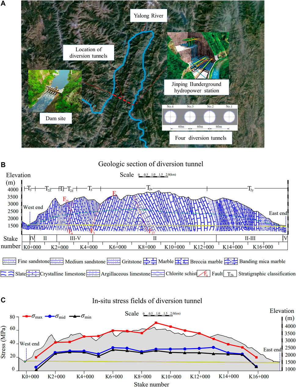
FIGURE 1. Geological Conditions. (A) Location of the diversion tunnels at Jinping II hydropower, (B) Geologic section of the diversion tunnels at Jinping II hydropower project, (C)In-situ stress fields of the diversion tunnels at Jinping II hydropower project.
Along the diversion tunnels, the main lithology of the strata is marble, slate, sandstone, and limestone. Along the reverse water flow direction of the diversion tunnels, they are Yantang Formation (T2y), Baishan Formation (T2b), Triassic Upper Series (T3), Zagunao Formation (T2z), and Triassic Lower Series (T1), respectively (Figure 1B). Among them, the Yantang Formation (T2y) mainly distributes in the Dashuigou area, and the core of the Laozhuangzi anticline is composed of marble and argillaceous limestone. The marble of the Baishan Formation (T2b) mainly distributes in the middle of the project area, which forms the main part of the Jinping Mountains. The Baishan marble (T2b) is stable and compact, and the thickness of the whole layer is 750–2,270 m. The Upper Triassic (T3) mainly distributes in the main watershed, and its lithology is sandstone and slate. The Lower Triassic (T1) stratum mainly distributes in the western part of the tunnel area, and its lithology is complex, which is composed of biotite chlorite schist, metamorphic medium-fine sandstone with thin-bedded marble, gravel or banded marble, etc.
2) Geological structure
In the project area, the folds are extremely developed and complicated, and most of them are dense folds extending near the SN direction (NNE). Generally, these folds are composed of three belts: east, middle, and west. Through the geological survey, it is revealed that compression bedding and NE-trending thrust faults are the main structural planes in the project area. Based on different structural features and distribution orientations, these planes are classified into four tectonic groups: NNW, NNE, NW∼NWW, and NE∼NEE. The main faults that the diversion tunnel passed through are F5, F6, F25, and F27, which are shown in Figure 1B. The attitude of F5 fault is N10°∼30°E, NW∠70°, with an affecting width of 5–10 m. The occurrence of the fault F6 is N20°∼50°E, NW or SE∠60°∼87°with the bandwidth of 1–4.2 m. The attitude of the F27 fault tends to the N30∼40°W direction, which is located in the middle of the Ganhaizi Formation and distributes in the Baishan Formation (T2b). The attitude of the fault F25 is N20°E, SE∠70°with a crushing bandwidth of 1–2 m.
3) In-situ stress fields
Because of the complex geological conditions and large burial depth, the in-situ stress at the construction area of four diversion tunnels is relatively high. Using the hydraulic fracturing method, the in-situ stress field at the construction area was measured (see Figure 1C). From Figure 1C, the maximum principal stress (σmax) reaches 72 MPa with a dip angle of 6.45–75.4°. The middle principal stress (σmid) reaches 34 MPa with a dip angle of 25°and is approximately perpendicular to the tunnel axis. For the minimum principal stress (σmin), it reaches about 29 MPa in the vertical direction with a dip angle of 65°.
In the tunnel area, the lithology of the rock mass is mostly pure and brittle marble with high strength. Due to the large burial depth, the rock mass is endowed with high in-situ stress. These two factors constitute the basic conditions for the occurrence of rockbursts. Subsequently, influenced by the blasting excavation induced disturbance, the rockburst occurred frequently (Figure 2).
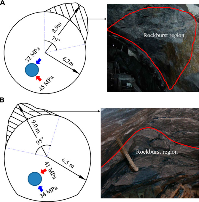
FIGURE 2. Rockburst occurred during excavation of diversion tunnels at Jinping II hydropower project. (A) At No. 1 diversion tunnel, (B) At No. 2 diversion tunnel.
To analyze the evolution mechanism of rockbursts induced by blasting excavation, the rockbursts that occurred at No. 2 diversion tunnel from stake number K10+600 to K17+000 were observed and recorded, as shown in Table 1. Otherwise, the rockburst intensity at the No.2 diversion tunnel and the rockburst frequency around the tunnel cross-section is given in Figure 3. According to Figure 3, there were 75 rockbursts during the blasting excavation of No. 2 diversion tunnel from stake number K10+600 to K17+000, and the majority of the rockbursts forms were exfoliation, lump flick, and peeling. From the field observation, the surface of the rockburst crater is fresh, showing the characteristics of "shallow pit", "deep pit" and "V-shape". The crater length of the rockburst at the No.2 diversion tunnel ranges from 1 m to 72 m, and the crater depth of the strongest rockburst reached 1.5∼3.0 m. According to the length and depth of the rockburst crater, the rockburst intensity is mainly divided into four grades: slight rockburst (I), medium rockburst (II), intense rockburst (III), and drastic rockburst (IV). Among these four grades, the different rockburst grades correspond to the different sizes of rock fragments. In general, the higher the rockburst grade means the deeper crater, the larger size of rock fragments, the farther the ejection distance of rock fragments caused by rockbursts, and the louder the sound produced by rockbursts.
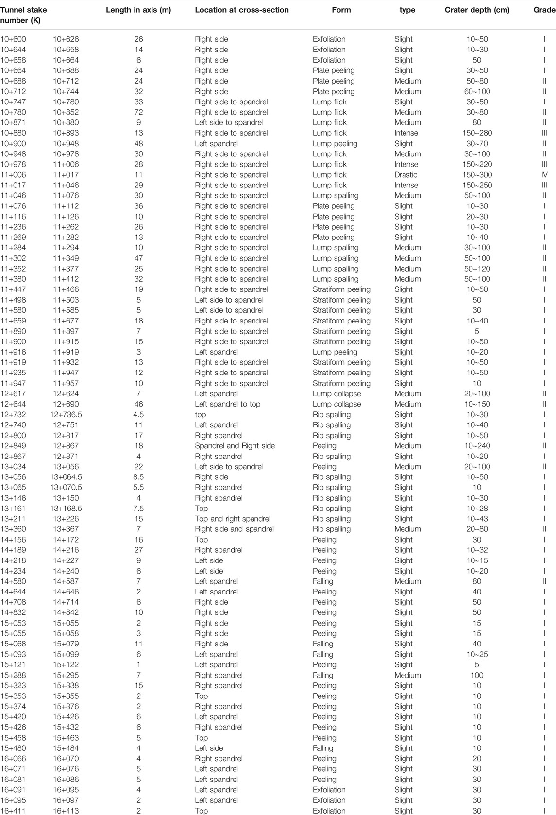
TABLE 1. Rockbursts occurred at No. 2 diversion tunnel from stake number K10+600 to K17+000.
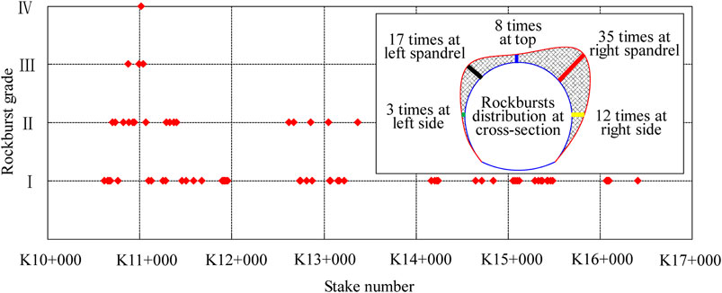
FIGURE 3. Rockburst grade along the tunnel axis and rockburst frequency at the tunnel cross-section.
Combined with Table 1, Figures 1B,C and Figure 3, the frequency and intensity of the rockbursts that took place near the stake number K11+000 were more drastic than those that took place near stake number K16+000, which indicates that rockbursts tend to occur around the tunnel cross-section with high in-situ stress and buried depth. Since No. 2 diversion tunnel was excavated by the upper and lower step method, almost all of the rockbursts happened at the upper section of the tunnel. Among the total frequency of the rockbursts that happened at the No.2 diversion tunnel, 35 rockbursts took place at the right spandrel, and 17 rockbursts occurred at the left spandrel. In addition, 12, 8, and 3 rockbursts happened at the right side, top and left side of the tunnel cross-sections, respectively.
From Figures 1B,C and Figure 3, we can also find that from stake number K16+000 to K11+000, the intensity, frequency, and rockburst grade enlarge with the increase of burial depth. Furthermore, it can also be seen from the figures that the burial depth is not the only influencing factor. There is a close correspondence between the rockburst frequency and the geological structure (syncline, anticline) along the tunnel axis, which indicates that the impact of geological structures on the in-situ stress field is another important factor that induces rockbursts. To facilitate the classification of rockbursts, we regarded the sporadic rockburst and continuous rockburst as the low-grade rockburst and high-grade rockburst, respectively. Generally, the intensity and grade of rockbursts are closely related to the level of in-situ stress.
When excavating No. 2 diversion tunnel by blasting, rockbursts happened frequently, which caused work stoppage more than once and increased the lining and support costs. As a man-made engineering disaster, rockbursts are not only harmful to the stability of the rock mass near the excavation area, they also threaten the security of workers and mechanical equipment near the occurrence area. Thus, it is crucial to evaluate the rockburst risk during excavation of a deep tunnel by blasting. High in-situ stress inevitably endows high strain energy to the rock mass, which may be released in some forms by the rock mass after blasting excavation. Many studies have reported that the rockburst is a mechanical failure phenomenon caused by the energy release of the rock mass (Wang and Park, 2001; He et al., 2010; Su, et al., 2017; Su, et al., 2018; Chen, et al., 2019). Thus, the key to revealing the evolution mechanism of rockbursts is to explore the energy release regularities that result from blasting excavation of a deep-buried tunnel.
Because rockbursts are the brittle failure induced behaviour of rock masses, the mechanical property, especially the post-peak mechanical characteristic of Jinping marble should be first studied to investigate the evolution mechanism of the rockburst that took place during the blasting excavation of No. 2 diversion tunnel. Previous research has reported that the stress-strain response and the yield form of the marble do not present as a single pattern under the action of compressive stress, but are closely associated with the value of confining pressure. For instance, in the case of low confining pressure, the stress-strain curve of the marble drops rapidly after reaching peak strength. This shows that the marble presents brittle characteristics like granite under low confining pressure. Accompanied with the continuous rise of confining pressure, it shows that the stress-strain curve slowly declines and the marble after the peak has a definite bearing capacity. While the confining pressure increases to a high level, the stress-strain curve of the marble after the peak does not decline and the residual strength of the marble still stays constant, presenting perfectly plastic characteristics. Therefore, the marble after the peak presents the brittle-ductile-plastic (BDP) transition characteristic during the rising process of confining pressure (Wawersik and Fairhurst, 1970). This particular mechanical property leads to the marble after the peak, which still has a high bearing capacity under the high confining pressure and stores a large amount of strain energy, which may be abruptly released and cause rockbursts under the disturbance of the tunnel excavation. Hence, studying and describing the BDP transition characteristics of Jinping marble is not only important for revealing the energy release regularities resulting from the transient stress unloading on the excavation boundary, but also are helpful for further understanding the evolution mechanism of the rockburst that happened during the construction of No. 2 diversion tunnel.
Aiming at investigating the special mechanical properties of Jinping marble, marble samples with a burial depth of 2000 m were drilled and obtained at the east end of the auxiliary tunnel for testing (Chu, 2009). Using the MTS pressure test equipment, a triaxial compression test was performed (see Figure 4). The test result in Figure 4 indicates that the Jinping marble sample shows significantly brittle characteristics after reaching peak strength under low confining pressure (2 MPa). While the confining pressure rises to the level of 2∼8 MPa, the residual strength of the marble sample drops a little and retains a high value after the peak. It shows that the marble sample starts presenting ductility features. As the confining pressure rises to a level of 40 MPa, the residual strength of the marble sample after the peak does not reduce and shows perfectly plastic characteristics.
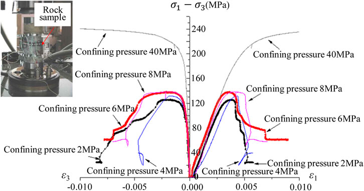
FIGURE 4. Triaxial compression tests of Jinping T2b marble samples.
To reveal the energy release regularity derived from the transient stress unloading during the tunnel excavation of the Jinping II hydropower project, first and foremost, the post-peak mechanical property of Jinping marble needs to be described. In the Hoek-Brown strength criterion, the mechanical parameters mb, s, a, etc. can be changed with the increase of plastic strain
here, mb, s, and a are strength parameters relating to the quality evaluation of the rock mass GSI, the material parameters of the rock mass mi; σ1, σ3, and σci are the first principal stress, third principal stress, and uniaxial compressive strength of the material, respectively.
In the above strength criterion, the rule is assumed that the maximum plastic strain increment
here, γ is the factor associated with the stress level, and its value is updated in each calculation step with the increment of plastic strain. According to the yield stress level, four kinds of flow rules can be achieved by the Hoek-Brown strength criterion.
1) Associated flow rule
The rule for associated flow:
Substituting Eq. 1 and Eq. 2 into Eq. 3, the associated flow factor γaf can be obtained by the following formula:
The associated flow rule is employed for the description of yield characteristics under the low confining pressure condition.
2) Isovolumetric flow rule
In the case of the higher confining pressure (
here, γif is the isovolumetric flow factor.
3) Radial flow rule
The rule is written by:
here, γrf is the radial flow factor.
The radial flow rule can describe the tensile failure of rock masses under the action of the tensile stress.
4) Combination flow rule
When the confining pressure ranges from 0 to
here, γcf is the combination flow factor.
Only the above four kinds of flow rules are still insufficient to describe the BDP transition characteristic of Jinping marble. To solve this issue, a scaling factor μ associated with the minimum principal stress σ3 was proposed by Cundall et al. (2003) to simulate the softening and hardening characteristic of the rock mass after yielding. By adjusting the value of the factor μ, it can be used to describe the variation characteristic of the strength parameters mb, s, a, etc. changing with the plastic strain under the different confining pressure conditions. Using the scaling factor μ, the brittle failure of granite was successfully described by Diederichs, on this basis, the "V-shape" failure was reproduced at the Canadian underground research laboratory (Diederichs, 2007). To describe the BDP transition characteristic of Jinping marble, the scaling factor μ and 8 parameters including 4 peak intensity parameters and 4 residual strength parameters should be first determined (Zhang et al., 2010). By triaxial compression test, the peak and residual strength parameters were acquired, which are given in Table 2 and Table 3. As for the determination of scaling factor μ, in this paper, the comparison method of the numerical simulation and the actual measured result of damage zones was adopted. For example, various conditions corresponding to different scaling factors μ were assumed, and then the in-situ stress unloading caused stress change path and damage zones of the surrounding rock mass were simulated using the assumed scaling factor μ. If the low stress distribution region and the extent of damage zones obtained by numerical simulation are consistent with the range of the low velocity distribution belt in the surrounding rock mass measured by the field acoustic wave test, it means that the right scaling factor μ has been found. Due to the troublesome process, here only two assumed conditions are introduced (Table 4).
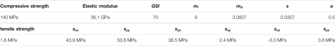
TABLE 2. Hoek-Brown mechanical parameters and in-situ stress field at K11+105 cross section.
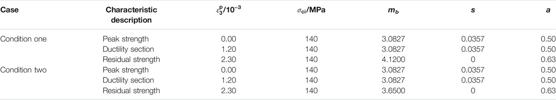
TABLE 3. Strength parameters of rock mass change with the plastic strain.

TABLE 4. Scaling factor changes with the minimum principal stress.
Condition one: the rock mass presents the brittle characteristic at the low confining pressure (0–2 MPa). The mechanical property transition of ductile-plastic occurs with the confining pressure reaching the level of 16 MPa.
Condition two: the ductile-plastic transition happens when confining pressure reaches 25 MPa.
Adopting the parameters given in Table 2, Table 3 and Table 4, taking the blasting excavation of No.2 diversion tunnel as an instance, the stress change path of the rock mass at a certain position of the surrounding rock mass under the disturbance of transient stress unloading on the excavation boundary was simulated, as shown in Figure 5. During the numerical modelling, the non-reflecting boundary condition was adopted, the stress dynamic adjustment processes of the rock mass elements which have a 30°angle with the x-axis (hole 4#) and have 1.0, 1.5, 2.0, 2.5, 3.0 m distance from the excavation boundary were recorded (Figure 5). In Figure 5, the fitting curve of peak strength and residual strength is also drawn. Figure 5A also presents that when the confining pressure reaches 16 MPa, the fitting curve of peak strength intersects the fitting curve of residual strength for condition one. It indicates that the confining pressure of the ductility-plastic transition is 16 MPa. While for condition two, the confining pressure of the ductility-plastic transition is 25 MPa (Figure 5B).
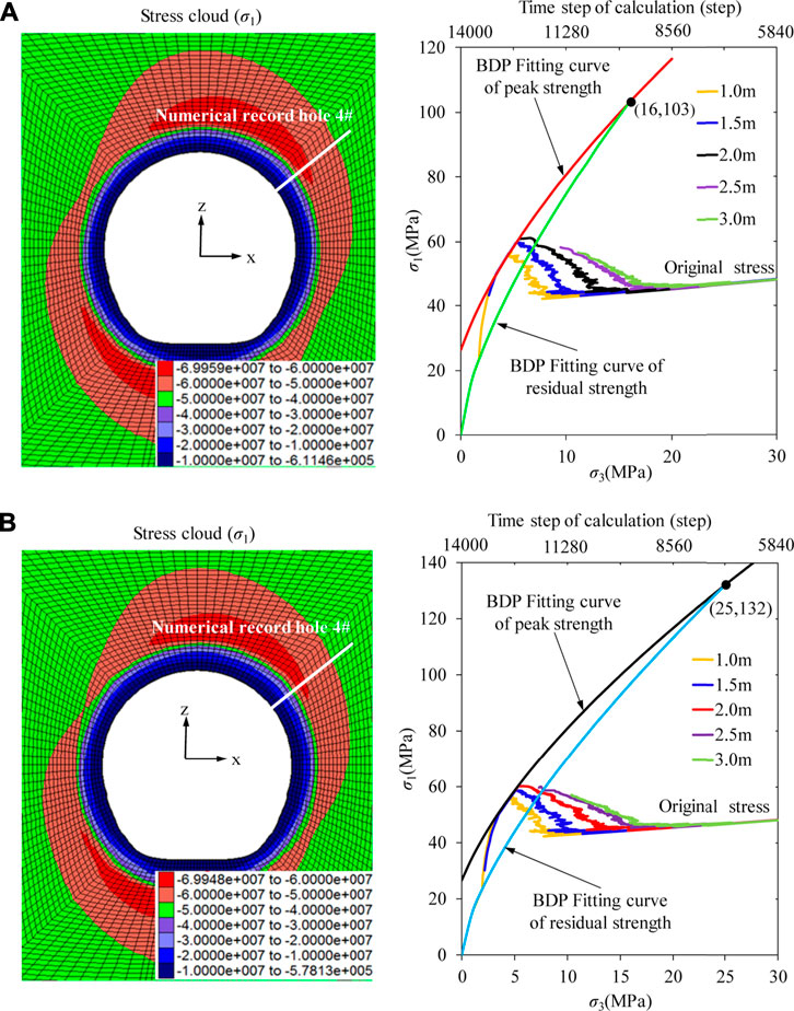
FIGURE 5. Stress path of surrounding rock masses induced by excavation. (A) Condition one, (B) Condition two.
In Figure 5, when the stress path curve intersects the fitting curve of peak strength, it means that the rock mass element is damaged, and the larger falling of the stress path curve means there is worse damage to the surrounding rock mass. For condition one, the stress paths of the surrounding rock mass elements with the distances of 1.0 and 1.5 m from the excavation boundary both have a significant drop after reaching the fitting curve of peak strength, but the stress path of the surrounding rock mass element with 2.0 m distance from the excavation boundary does not fall. Therefore, the damage depth of the surrounding rock mass has a 30°angle with the x-axis (hole 4#) can be determined as 2.0 m. While for condition two, the stress path curve of the surrounding rock mass element with a distance of 2.0 m from the excavation boundary only has a slight drop after reaching the fitting curve of peak strength. The stress path curve of the surrounding rock mass element with a 2.5 m distance from the excavation boundary does not reach the fitting curve of peak strength, it means that the extent of damage to the surrounding rock mass is within 2.0∼2.5 m. By further drawing the stress path curve of the rock mass element with a 2.0∼2.5 m distance from the excavation boundary, it was found that the damage depth was 2.3 m at this location.
More simply, a square model (1 × 1 × 1 m) was set up to simulate the rock sample, and the numerical stress-strain curve in several confining pressure conditions was performed (Figure 6). As can be seen from Figure 6, the confining pressure plays a critical role in the mechanical characteristic of the marble after the peak. When the confining pressure is low (0∼2 MPa), the stress-strain curve falls quickly after the peak and presents the obviously brittle characteristic like granite, and there is still a significant difference between the peak strength and the residual strength. However, this difference continually declines with the rise of the confining pressure. While the confining pressure exceeds 10 MPa, the stress-strain curve does not fall quickly after yielding and shows a significantly ductile characteristic. When the numerical rock sample is under high confining pressure, the stress-strain curve does not decline after the peak and shows an ideally plastic characteristic. For condition one, the confining pressure 16 MPa is the ductility-plastic transition threshold. While for condition two, the confining pressure 25 MPa is the ductility-plastic transition threshold. Both conditions one and two can describe the BDP transition property of the marble. To deduce which condition is right, a verification using the field acoustic wave test needs to be performed.

FIGURE 6. Axial stress-strain curves under different conditions.
The field acoustic wave test result of the cross-section K11+105 is given in Figure 7. From Figure 7, the damage depth of the surrounding rock mass which has a 30°angle with the x-axis (hole 4#) is 2.0 m. It can be found that the test result is consistent with the numerical simulation result of condition one in Figure 5A. On this basis, using the parameters of condition one, the damage zone of the surrounding rock mass resulting from tunnel excavation was simulated (see Figure 7). In Figure 7, we can find that except for hole 2#, there is little difference between the damage extent of simulation results and the damage extent of field test results, which proves that the simulation method adopted in this paper is correct. Because the indoor test presented in Figure 4 is hard to reproduce the real loading and unloading stress path of the surrounding rock mass, it may lead to the numerical axial stress-strain curves in Figure 6 being inaccurate. This is why the axial stress-strain curves of simulation results in Figure 6 are different from that of indoor test results in Figure 4, but the simulation result of the damage zone is the same as the field test result.
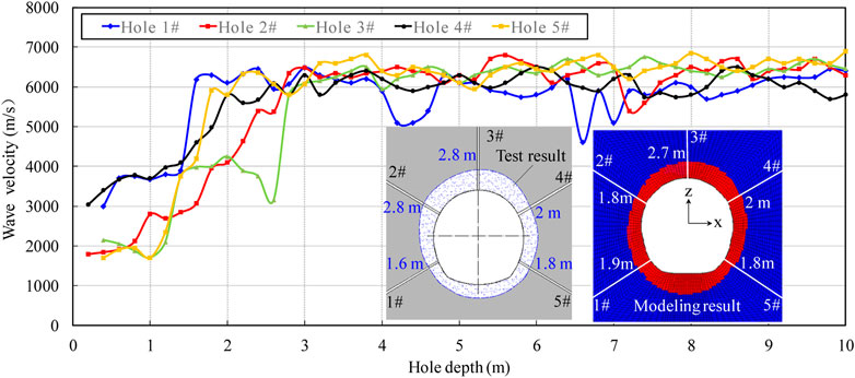
FIGURE 7. Field test results of acoustic wave and excavation induced damage zone at K11+105 cross section.
A simple assumption was made that an infinite-long tunnel is excavated with a radius of R in the initial hydrostatic stress field P0. Then, the stress adjustment process of the surrounding rock mass due to the quasi-static unloading of in-situ stress can be calculated by Eq. 8:
here, r is the distance between the rock mass and the excavation centre, σθ and σr are the circumferential stress and radial stress, respectively, and σ1, σ2, σ3 are the principal stresses.
After the calculation of principal stresses, the density of elastic strain energy can be counted by Eq. 9 (Solecki and Conant, 2003):
here, υ is the Poisson’s ratio, E0 is the elastic modulus, and U is the elastic strain energy density of the rock mass at a certain location.
Before tunnel excavation (σ1=σ2=σ3=P0), the initial rock mass is intact and its strain energy density is counted by:
here, U0 is the initial strain energy density of rock masses before the tunnel excavation.
When the unloading process is completed, the strain energy density of the surrounding rock mass can be obtained by substituting Eq. 8 into Eq. 9:
here, UA is the strain energy density of the surrounding rock mass at a certain position after stress unloading.
Comparing Eq. 10 and Eq. 11, it is not difficult to find that after the in-situ stress unloading induced by tunnel excavation, the strain energy density of the surrounding rock mass increases.
It is generally acknowledged that as a brittle material, there is a limit for the strain energy storage capacity of the rock mass. Based on the hydrostatic compressive pressure field considered in this research, the energy storage limit of the rock mass Uc for the case of three-dimensional pressure can be calculated by Eq. 12 (Xie et al., 2005):
Under the condition of the quasi-static unloading, Uc is acquired by substituting Eq. 8 into Eq. 12:
From Eq. 13 and Eq. 11, it can be found that the shorter distance to the excavation centre, the weaker the energy storage capacity of the rock mass, and the more the strain energy will accumulate in the rock mass. Consequently, when it is close to the excavation boundary, the strain energy aggregated in the surrounding rock mass can easily exceed the storage limit, which will inevitably lead to the energy release and cause damage, even failure in the surrounding rock mass.
When the blasting excavation method is employed, the stress unloading process on the excavation face is rapid and transient but not a quasi-static process (Lu et al., 2012; Li et al., 2014; Zhu et al., 2014; Fan et al., 2015). The transient stress unloading induced stress field in the surrounding rock mass can be calculated by employing inversion integral, contour integration, and Laplace transform (Fan et al., 2016):
here:
here, Cp is the P-waves velocity, t and t0 is the time and unloading time, respectively, σθ(r, t) and σr(r, t) is the dynamically circumferential stress and radial stress of the surrounding rock mass induced by transient unloading, respectively, η is the integral path, G is the Lame constant, J0, J1, Y0, and Y1 are the Bessel functions.
After calculation, the dynamically circumferential stress and radial stress of the surrounding rock mass are drawn in Figure 8A. From Figure 8A, compared with quasi-static unloading, transient unloading will enlarge the effect of radial unloading and circumferential loading in the surrounding rock mass, and result in a larger difference between the first and third principal stress. Combining this dynamic adjustment process with Eq. 12, the transient stress unloading will reduce the energy storage limit and tends to result in energy release.
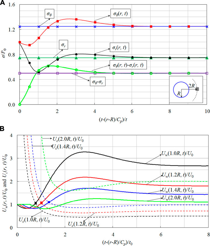
FIGURE 8. Dynamic response induced by transient unloading of in-situ stress. (A) Dynamic stress of surrounding rock masses induced by transient unloading of in-situ stress (r = 2R), (B) Variation process of strain energy density and energy storage limit induced by transient unloading of in-situ stress.
Substituting the dynamic stress field of Figure 8A into Eq. 9, the strain energy density of the surrounding rock mass Uw(r, t) under the transient stress unloading can be calculated. To show the variation process of strain energy intuitively, the ratios of the strain energy density Uw(r, t) and energy storage limit Uc(r, t) to the initial strain energy density U0 of the surrounding rock mass at 1.0R, 1.2R, 1.4R, and 2.0R are drawn in Figure 8B. As can be seen from Figure 8B, the strain energy experiences a dynamic variation process like declining at first, raising second and stabilizing at last. In fact, before the strain energy reaches the peak value of the elastic change curve as shown in Figure 8B, it will exceed the energy storage limit and result in energy release. Obviously, under elastic conditions, the subsequent curve after the strain energy density curve intersecting with the energy storage limit curve is not the actual energy adjustment process.
On the purpose of evaluating the rockburst intensity, Cook proposed a new index, energy release rate (ERR), which can be counted by Eq. 16:
here, Es is the total value of released energy; Ee and Ve are the total strain energy and volume of the excavated rock mass, respectively.
Since the energy release rate (ERR) cannot reflect the intensity and location of the energy release in the surrounding rock mass, it fails to identify the occurrence position of the rockburst. To achieve this goal, an index of local energy release rate (LERR) was proposed by Jiang et al. (2010) for describing the energy release resulting from the tunnel excavation. This index is acquired by counting the difference value between the strain energy density before the material failure and the strain energy density after the material failure:
here, LERRi is LERR of the rock mass element; Uipeak is the peak value of strain energy density of the rock mass element before the brittle failure; Uitrough is the trough value of strain energy density of the rock mass element after the brittle failure; i is the number of the rock mass element; Uipeak and Uitrough are counted by Eq. 9.
From Figure 8B, it can also be seen that the residual value of strain energy density may be higher than the trough value of strain energy density under the elastic condition after the brittle failure occurring. Therefore, Eq. 17 should be corrected:
here, Uimax is the maximum value of strain energy density for the i-th rock mass element before the brittle failure happens; Uis is the final stable value or the residual value of strain energy density after the brittle failure.
The same model (Figure 9A) and parameters in section 3.2 were adopted to analyze the energy release process due to excavation. Before excavation, adopting the ideal and elastic model, the initial in-situ stress field and strain energy of rock masses was calculated. Through a certain calculation time step, the balance was obtained and the simulation result is shown in Figure 9B. During the numerical simulation of the energy release process, the non-reflecting boundary condition, i.e. the energy absorption boundary condition mentioned in Section 3.2 was adopted. Then, based on the parameters in Table 2, Table 3, and Table 4 and the BDP model, the energy accumulation of the surrounding rock mass due to tunnel excavation was simulated as shown in Figure 9C. From the simulation result presented in Figure 9C, it was found that due to the low storage limit of the surrounding rock mass around the excavation boundary, the accumulated strain energy easily exceeds the energy storage limit. Subsequently, energy release happens and triggers off the failure of the surrounding rock mass. After the energy release process is complete, the strain energy stabilizes at the residual state, as in Figure 9D.
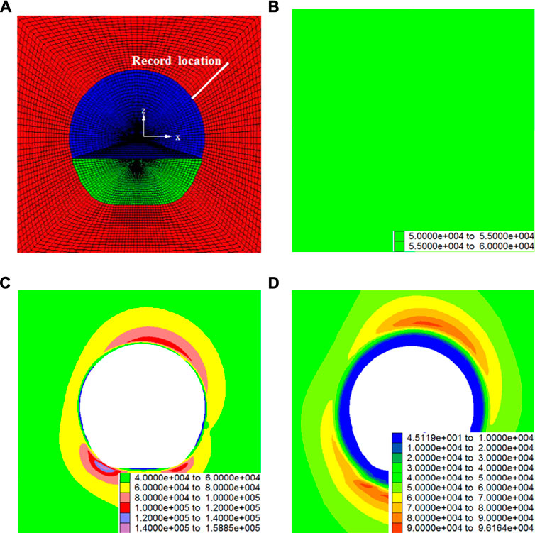
FIGURE 9. The variation of strain energy due to tunnel excavation (J/m3): (A) Calculation model, (B) Strain energy of initial rock masses before excavation, (C) Strain energy accumulation in surrounding rock masses, (D) residual state of strain energy in surrounding rock masses.
To reveal the dynamic process of energy release resulting from transient stress unloading, the strain energy density of the surrounding rock mass elements with the distances of 0.5, 1.0, 1.5, and 2.0 m from the excavation boundary (Figure 9A) were recorded, which is drawn in Figure 10.
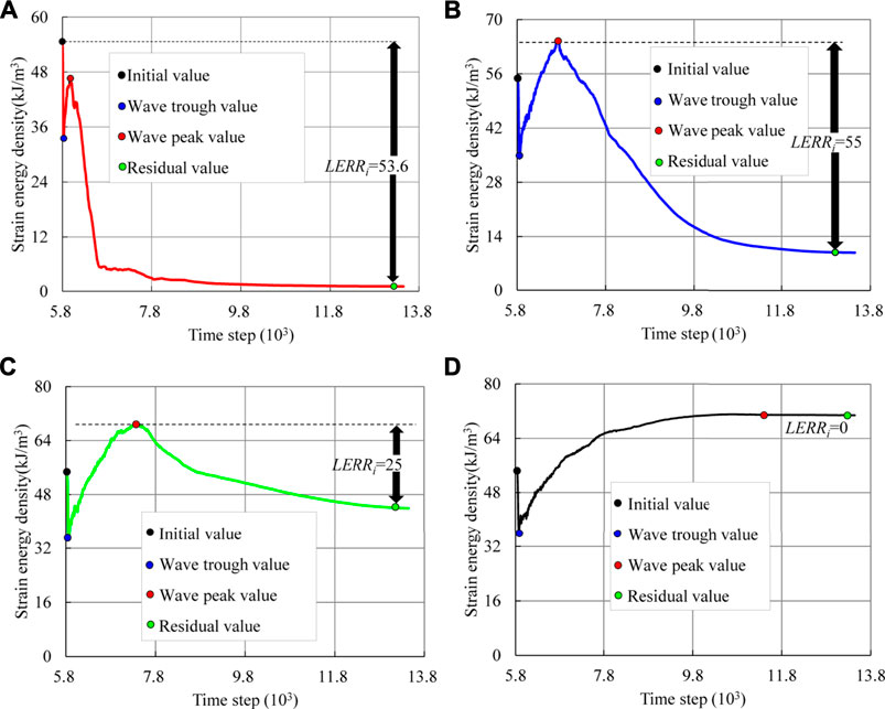
FIGURE 10. Energy release process of surrounding rock masses induced by the transient unloading of in-situ stress: (A) Rock mass element with a distance of 0.5 m from the excavation boundary, (B) Rock mass element with a distance of 1.0 m from the excavation boundary, (C) Rock mass element with a distance of 1.5 m from the excavation boundary, (D) Rock mass element with a distance of 2.0 m from the excavation boundary.
Figure 10 shows that the strain energy adjustment curve has two significant amplitude values: the peak value and the trough value. For the rock mass element which is 0.5 m away from the excavation boundary (Figure 10A), the peak value of the strain energy density is smaller than its initial value. While for the rock mass element with distances of 1.0 and 1.5 m from the excavation boundary, the peak value of the strain energy density is greater than the initial value (see Figures 10B,C). This illustrates that due to transient stress unloading, the strain energy of the distant rock mass will flow to the excavation boundary and lead to the accumulated energy more easily exceeding the energy storage limit for the rock mass, which is near the excavation boundary. Thus, when the strain energy accumulates in the surrounding rock mass, it cannot reach the peak value like Figure 8B under the ideally elastic conditions, it can even be smaller than the initial value of the strain energy before excavation unloading. Therefore, it is inaccurate to use the difference value of the peak value and trough value (Eq. 17) when calculating the local energy release rate.
Figure 10 indicates that for the surrounding rock mass elements which are 0.5, 1.0, and 1.5 m away from the excavation boundary, the strain energy experiences a variation process of reducing firstly, raising secondly, then decreasing and finally stabilizing. Similar to the elastic conditions, the first reduction of strain energy will not trigger failures in the surrounding rock mass, because it is induced by the elastic unloading wave. However, the second decline of the strain energy results from the factor that the strain energy absorbed in the surrounding rock mass, which is greater than the storage limit, which will inevitably lead to the brittle failure of the surrounding rock mass. A further observation from Figure 10, it is not difficult to find that with the decrease of the distance between the rock mass and the excavation boundary, the energy release duration is shorter, and the local energy release rate is greater. These characteristics mean that the shorter distance from the rock mass to the final excavation boundary, the more violent energy release occurs.
For the deep tunnel excavation, the energy release is the inherent factor of the dynamic failure of the surrounding rock mass such as rockbursts (Hodgson and Joughin, 1966; Toksöz and Kehrer, 1972; Singh, 1988; Mikhalyuk and Zakharov, 1997; Wang and Park, 2001; He et al., 2010). Therefore, establishing a certain association of the energy release and the rockburst is crucial to predicting and controling the rockburst induced by the deep tunnel excavation. Based on the concept of LERR, the average value of the local energy release rate
here, Vf is the total volume of the failure elements in surrounding rock masses.
Based on the recorded rockbursts in Table 1, the average value of
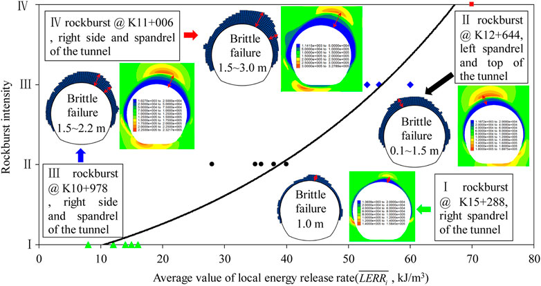
FIGURE 11. Relationship between the average value of local energy release rate (
Using the numerical simulation method proposed above, the average value of
The rockburst prediction is challenging work for researchers and engineers. Since the energy release plays a significant role in the formation of the rockburst, it has been the subject of much attention. The association between the rockburst intensity and the energy release rate (ERR) was developed by South African researchers, which can be expressed as:
The magnitude in Eq. 20 is significantly different from that in Figure 11. Considering a simple case, under the burial depth of 1,000∼2000 m, an underground tunnel is excavated with the in-situ stress of 27∼54 MPa (assumption: υ=0.25, E0=20∼50 GPa). On this basis, the initial strain energy density of the rock mass can be estimated by Eq. 10. After calculation, the initial strain energy density of the surrounding rock mass only reaches 10.9–109.4 kJ/m3, which is similar to the magnitude in Figure 11. From this point of view, the prediction method of rockbursts proposed in Figure 11 is better than that in Eq. 20.
The fault, structural plane, and excavation method were not considered in this paper but they also play a key role in the energy release and rockburst characteristics. Thus, the prediction method proposed for the rockburst (Figure 11) still requires verification. Despite these limitations, this research provides new insights to reveal energy variation regularity and assess the rockburst risk during the excavation of the deep tunnel by blasting.
Considering the special post-peak mechanical property of Jinping marble, the BDP transition property of Jinping marble was numerically simulated. Using the correct BDP model after verifications, we analyzed the transient stress unloading induced by the dynamic energy release process. Due to the transient unloading, the strain energy of the surrounding rock mass goes through a process of firstly decreasing, secondly increasing, next reducing, and finally stabilizing. Similar to the elastic conditions, the first decrease of strain energy results from the elastic unloading wave, which will not trigger the energy release and brittle failure. The second reduction of strain energy is owed to the factor that a quantity of strain energy accumulates in the surrounding rock mass and exceeds the storage limit of the surrounding rock mass, which inevitably causes the energy release and brittle failure of the surrounding rock mass. According to the theoretical calculation and numerical calculation, the shorter distance from the surrounding rock mass to the final excavation boundary means that the energy storage capacity of the surrounding rock mass is weaker, the intenser energy release, and the more drastic rockburst. Finally, to investigate the association of the energy release and rockburst due to the tunnel excavation, a numerical relationship between the average value of
This research only reveals the dynamic energy release process derived from transient stress unloading and established the relationship between the average value of
The raw data supporting the conclusions of this article will be made available by the authors, without undue reservation.
XC, ZL, JZ, FW, and XX contributed to the writing of the manuscript. YF led the field work. All authors contributed to giving constructive reviews and suggestions.
This work was supported by the National Natural Science Foundation of China (51979152), Educational Commission of Hubei Province of China (T2020005), Open Foundation of Hydraulic Rock Mechanics of Ministry of Education (RMHSE1603), Open Foundation of Hubei Key Laboratory of Construction and Management in Hydropower Engineering (2016KSD11).
Author ZL is employed by China Gezhouba Group Explosive Co. Ltd.
The remaining authors declare that the research was conducted in the absence of any commercial or financial relationships that could be construed as a potential conflict of interest.
All claims expressed in this article are solely those of the authors and do not necessarily represent those of their affiliated organizations, or those of the publisher, the editors and the reviewers. Any product that may be evaluated in this article, or claim that may be made by its manufacturer, is not guaranteed or endorsed by the publisher.
The authors would like to thank all the supporters.
Alija, S., Torrijo, F. J., and Quinta-Ferreira, M. (2013). Geological Engineering Problems Associated With Tunnel Construction in Karst Rock Masses: the Case of Gavarres Tunnel (Spain). Eng. Geology. 157 (4), 103–111. doi:10.1016/j.enggeo.2013.02.010
Alija, S., Torrijo, F. J., and Quinta-Ferreira, M. (2014). Study of the Unexpected Collapse of the Ampurdán Tunnel (Spain) Using a Finite Elements Model. Bull. Eng. Geol. Environ. 73 (2), 451–463. doi:10.1007/s10064-013-0534-z
Brady, B. H. G., and Brown, E. T. (1981). Energy Changes and Stability in Underground Mining: Design Applications of Boundary Element Methods. Inst. Mining Metall. Trans. 90, 61–68.
Chen, Z., Su, G., Ju, J. W., Jiang, J., and Jiang, J. Q. (2019). Experimental Study on Energy Dissipation of Fragments during Rockburst. Bull. Eng. Geol. Environ. 78 (5), 5369–5386. doi:10.1007/s10064-019-01463-9
Chu, W. J. (2009). Stability and Structure Safety Assessment of Surrounding Rock in Deep Buried Tunnel. Hangzhou, China: Postdoctoral research report of Hydro China Huadong Engineering Corporation.
Cook, N. G. W., Hoek, E., Pretorius, J. P. G., Ortlepp, W. D., and Salamon, M. D. G. (1966). Rock Mechanics Applied to the Study of Rockbursts. J. South Afr. Inst. Mining Metall. 66 (10), 436–528.
Cook, N. G. W. (1976). Seismicity Associated With Mining. Eng. Geology. 10 (2), 99–122. doi:10.1016/0013-7952(76)90015-6
Cundall, P., Carranza-Torres, C., and Hart, R. (2003). “A New Constitutive Model Based on the Hoek–Brown Criterion,” in Proceedings of the 3rd international FLAC symposium. Editor R Brummer (Sudbury: Balkema), 17–25.
Diederichs, M. S. (2007). The 2003 Canadian Geotechnical Colloquium: Mechanistic Interpretation and Practical Application of Damage and Spalling Prediction Criteria for Deep Tunnelling. Can. Geotech. J. 44 (9), 1082–1116. doi:10.1139/T07-033
Fan, Y., Lu, W. B., Yan, P., Chen, M., and Zhang, Y. Z. (2015). Transient Characters of Energy Changes Induced by Blasting Excavation of Deep-Buried Tunnels. Tunnelling Underground Space Technology. 49, 9–17. doi:10.1016/j.tust.2015.04.003
Fan, Y., Lu, W., Zhou, Y., Yan, P., Leng, Z., and Chen, M. (2016). Influence of Tunneling Methods on the Strainburst Characteristics During the Excavation of Deep Rock Masses. Eng. Geology. 201, 85–95. doi:10.1016/j.enggeo.2015.12.015
Fan, Y., Zheng, J. W., Cui, X. Z., Leng, Z. D., Wang, F., and Lv, C. C. (2021). Damage Zones Induced by In Situ Stress Unloading During Excavation of Diversion Tunnels for the Jinping II Hydropower Project. Bull. Eng. Geol. Environ. 80 (8), 4689–4715. doi:10.1007/s10064-021-02172-y
Feng, X.-T., Xu, H., Qiu, S.-L., Li, S.-J., Yang, C.-X., Guo, H.-S., et al. (2018a). In Situ Observation of Rock Spalling in the Deep Tunnels of the China Jinping Underground Laboratory (2400 M Depth). Rock Mech. Rock Eng. 51 (4), 1193–1213. doi:10.1007/s00603-017-1387-8
Feng, X.-T., Guo, H.-S., Yang, C.-X., and Li, S.-J. (2018b). In Situ Observation and Evaluation of Zonal Disintegration Affected by Existing Fractures in Deep Hard Rock Tunneling. Eng. Geology. 242, 1–11. doi:10.1016/j.enggeo.2018.05.019
He, M. C., Miao, J. L., and Feng, J. L. (2010). Rock Burst Process of limestone and its Acoustic Emission Characteristics Under True-Triaxial Unloading Conditions. Int. J. Rock Mech. Mining Sci. 47 (2), 286–298. doi:10.1016/j.ijrmms.2009.09.003
Hodgson, K., and Joughin, J. C. (1966). The Relationship Between Energy Release Rate, Damage, and Seismicity in Deep Mines, The 8th U.S. Symposium on Rock Mechanics (USRMS), Minneapolis, Minnesota: Johannesburg.
Jiang, Q., Feng, X.-T., Xiang, T.-B., and Su, G.-S. (2010). Rockburst Characteristics and Numerical Simulation Based on a New Energy index: a Case Study of a Tunnel at 2,500 M Depth. Bull. Eng. Geol. Environ. 69 (3), 381–388. doi:10.1007/s10064-010-0275-1
Kisslinger, C. (1976). A Review of Theories of Mechanisms of Induced Seismicity. Eng. Geology. 10, 85–98. doi:10.1016/0148-9062(77)90067-5
Kramarenko, V. I., and Revuzhenko, A. F. (1988). Flow of Energy in a Deformed Medium. Soviet Mining Sci. 24 (6), 536–540. doi:10.1007/BF02498611
Li, X., Cao, W., Zhou, Z., and Zou, Y. (2014). Influence of Stress Path on Excavation Unloading Response. Tunnelling Underground Space Technology. 42, 237–246. doi:10.1016/j.tust.2014.03.002
Lindin, G. L., and Lobanova, T. V. (2013). Energy Sources of Rockbursts. J. Min Sci. 49 (1), 36–43. doi:10.1134/S106273914901005X
Lu, W., Yang, J., Yan, P., Chen, M., Zhou, C., Luo, Y., et al. (2012). Dynamic Response of Rock Mass Induced by the Transient Release of In-Situ Stress. Int. J. Rock Mech. Mining Sci. 53 (7), 129–141. doi:10.1016/j.ijrmms.2012.05.001
Martino, J. B., and Chandler, N. A. (2004). Excavation-Induced Damage Studies at the Underground Research Laboratory. Int. J. Rock Mech. Mining Sci. 41 (8), 1413–1426. doi:10.1016/j.ijrmms.2004.09.010
Mikhalyuk, A. V., and Zakharov, V. V. (1997). Dissipation of Dynamic-Loading Energy in Quasi-Elastic Deformation Processes in Rocks. J. Appl. Mech. Tech. Phys. 38 (2), 312–318. doi:10.1007/BF02467918
Mitri, H. S., Tang, B., and Simon, R. (1999). FE Modelling of Mining-Induced Energy Release and Storage Rates. J. South Afr. Inst. Mining Metall. 99 (2), 103–110.
Napier, J. A. L. (1991). Energy Changes in a Rockmass Containing Multiple Discontinuities. J. South Afr. Inst. Mining Metall. 91 (5), 145–157.
Read, R. S. (2004). 20 Years of Excavation Response Studies at AECL's Underground Research Laboratory. Int. J. Rock Mech. Mining Sci. 41 (8), 1251–1275. doi:10.1016/j.ijrmms.2004.09.012
Revuzhenkor, A. F., and Klishin, S. V. (2009). Energy Flux Lines in a Deformable Rock Mass with Elliptical Openings. J. Min Sci. 45 (3), 201–206. doi:10.1007/s10913-009-0026-5
Salamon, M. D. G. (1984). Energy Considerations in Rock Mechanics: Fundamental Results. J. South Afr. Inst. Mining Metall. 84 (8), 233–246. doi:10.1016/0022-3115(84)90073-4
Salamon, M. D. G. (1983). Rockburst hazard and the Fight for its Alleviation in South African Gold Mines, Proc. Rockbursts Prediction and Control. London: IMM, 11–36.
Singh, S. P. (1988). Burst Energy Release Index. Rock Mech. Rock Engng. 21 (2), 149–155. doi:10.1007/bf01043119
Solecki, R., and Conant, R. J. (2003). Advanced Mechanics of Materials. London: Oxford University Press.
Su, G., Jiang, J., Feng, X., Jiang, Q., Chen, Z., and Mo, J. (2018). Influence of Loading Rate on Strainburst: an Experimental Study. Bull. Eng. Geol. Environ. 78 (5), 3559–3573. doi:10.1007/s10064-018-1351-1
Su, G., Zhai, S., Jiang, J., Zhang, G., and Yan, L. (2017). Influence of Radial Stress Gradient on Strainbursts: an Experimental Study. Rock Mech. Rock Eng. 50 (10), 2659–2676. doi:10.1007/s00603-017-1266-3
Toksöz, M. N., and Kehrer, H. H. (1972). Tectonic Strain Release by Underground Nuclear Explosions and its Effect on Seismic Discrimination. Geophys. J. Int. 31 (1-3), 141–161. doi:10.1111/j.1365-246X.1972.tb02364.x
Walsh, J. B. (1977). Energy Changes Due to Mining. Int. J. Rock Mech. Mining Sci. Geomechanics Abstr. 14 (1), 25–33. doi:10.1016/0148-9062(77)90559-9
Wang, J.-A., and Park, H. D. (2001). Comprehensive Prediction of Rockburst Based on Analysis of Strain Energy in Rocks. Tunnelling Underground Space Technology. 16 (1), 49–57. doi:10.1016/S0886-7798(01)00030-X
Wawersik, W. R., and Fairhurst, C. (1970). A Study of Brittle Rock Fracture in Laboratory Compression Experiments. Int. J. Rock Mech. Mining Sci. Geomechanics Abstr. 7 (5), 561–575. doi:10.1016/0148-9062(70)90007-0
Xie, H. P., Ju, Y., and Li, L. Y. (2005). Criteria for Strength and Structural Failure of Rocks Based on Energy Dissipation and Energy Release Principles. Chin. J. Rock Mech. Eng. 24 (17), 3003–3010. doi:10.1007/s11769-005-0030-x
Yang, J. H., Jiang, Q. H., Zhang, Q. B., and Zhao, J. (2018). Dynamic Stress Adjustment and Rock Damage During Blasting Excavation in a Deep-Buried Circular Tunnel. Tunnelling Underground Space Technology. 71, 591–604. doi:10.1016/j.tust.2017.10.010
Yang, J., Lu, W., Jiang, Q., Yao, C., Jiang, S., and Tian, L. (2016). A Study on the Vibration Frequency of Blasting Excavation in Highly Stressed Rock Masses. Rock Mech. Rock Eng. 49 (7), 2825–2843. doi:10.1007/s00603-016-0964-6
Zhang, C. S., Chen, X. R., Hou, J., and Chu, W. J. (2010). Study of Mechanical Behavior of Deep-Buried Marble at JinPing II Hydropower Station. Chin. J. Rock Mech. Eng. 29 (10), 1999–2009.
Keywords: high in-situ stress, energy release, rockburst, transient unloading, deep tunnel
Citation: Fan Y, Cui X, Leng Z, Zheng J, Wang F and Xu X (2021) Rockburst Prediction From the Perspective of Energy Release: A Case Study of a Diversion Tunnel at Jinping II Hydropower Station. Front. Earth Sci. 9:711706. doi: 10.3389/feart.2021.711706
Received: 19 May 2021; Accepted: 08 July 2021;
Published: 03 September 2021.
Edited by:
Faming Huang, Nanchang University, ChinaReviewed by:
Jianhua Yang, Nanchang University, ChinaCopyright © 2021 Fan, Cui, Leng, Zheng, Wang and Xu. This is an open-access article distributed under the terms of the Creative Commons Attribution License (CC BY). The use, distribution or reproduction in other forums is permitted, provided the original author(s) and the copyright owner(s) are credited and that the original publication in this journal is cited, in accordance with accepted academic practice. No use, distribution or reproduction is permitted which does not comply with these terms.
*Correspondence: Junwei Zheng, amp1bndlaXpoZW5nQDE2My5jb20=
Disclaimer: All claims expressed in this article are solely those of the authors and do not necessarily represent those of their affiliated organizations, or those of the publisher, the editors and the reviewers. Any product that may be evaluated in this article or claim that may be made by its manufacturer is not guaranteed or endorsed by the publisher.
Research integrity at Frontiers
Learn more about the work of our research integrity team to safeguard the quality of each article we publish.