
95% of researchers rate our articles as excellent or good
Learn more about the work of our research integrity team to safeguard the quality of each article we publish.
Find out more
ORIGINAL RESEARCH article
Front. Earth Sci. , 13 May 2021
Sec. Structural Geology and Tectonics
Volume 9 - 2021 | https://doi.org/10.3389/feart.2021.683439
This article is part of the Research Topic Continental Basin and Orogenic Processes: Deep Structure, Tectonic Deformation, and Dynamics View all 24 articles
 Xiaogang Li1*
 Guoqiang Xu2*
 Chen Wu3An Yin4Shihu Wu5Andrew V. Zuza6Gang Chen7Zhiwu Li2Shaohua Xu1Yiwen Li1
Fault-fractured pore space is complex and difficult to predict and evaluate. For a single independent ramp-flat fault-bend fold structure, the pure void space between two fault walls equals the integrated fracture pore spaces within the fault damage zone if it were concentrated on the fault plane. Using an area balancing technique and geometrical relationship, we have developed a two-dimensional (2D) model to calculate the pore space of fractures associated with fault development. The development and distribution of fault detachment voids or fault fracture pore space are controlled by the physical properties of the deforming medium, mechanics of deformation, and geometry of a fault-ramp structure. We demonstrate how concordant or discordant folding of the fault wall rock affects the nature of fault-fracture pore space. The pure void space and fracture pores in the fault zone can be quantitatively described by the following parameters: initial ramp angle and height, overlap ramp length, throw and slipping displacement, stack thickness, curvature and derivation of the angle between bed and fault plane (Rθ), and dip isogons. Rθ reflects the conformity of two opposite fault sections and the folding accordance of two walls, and it is a key element for the development and distribution of fracture pore space in a fault zone. Furthermore, we observed natural outcrops supporting and validating our model assumptions in the foreland fault system, Central China.
Understanding and quantitatively predicting the formation, location, orientation, intensity, porosity, and permeability of natural fractures within a fault damage zone (Caine et al., 1996; Kim et al., 2004; Choi et al., 2016; Peacock et al., 2017) are not only important for hydrocarbon exploration and production planning activities (Aydin, 2000; Nelson, 2001; Smart et al., 2009; Feng et al., 2018) but also for site selection for large engineering projects and earthquake prevention and disaster reduction (Beach et al., 1999; Scholz, 2002; Huang and Li, 2009). Over the last few decades, a number of studies have focused on the prediction of fault-related fractures (Walsh and Watterson, 1988; Gross et al., 1995; Caine et al., 1996; Aarland and Skjerven, 1998; Nelson et al., 1999; Nelson, 2001; Xu et al., 2006; Li et al., 2012; Reyer et al., 2012; Choi et al., 2016; O'Hara et al., 2017; Liu et al., 2018). Here, we present a new perspective to quantitatively predict and evaluate the volume of fracture pore space for a single fault zone. Fracture pore space is the pore space between separated fracture walls or opening cracked rock surfaces, which has not been filled by external mechanical media during deformation. It is a different term to that defined by Howard (1990), whose definition referred to the present pore space. In this study, it refers to the pore space produced by deformation, which can be filled by hydrocarbon, water, and solid minerals. The term “pure void space” is an imaginary physical space that refers to the fault-ramp detachment void space at the particular ramp segment where rigid rock contacted with rigid rock, and it is an equivalent physical space which equals to the total space of fracture pores in the fault damage zone, so that it is a restored expression of fracture pores in the fault zone and is different from the real void space in the present-day fault fracture damage zone.
In general, the following elements have been proposed to address the development and position of fracture pore space: (1) the rigidity of strata located on both sides of the fault; (2) the fault scale; (3) the degree of folding of the hanging wall and the spatial relationship between folding and faulting; and (4) folding of the footwall rocks, and the relationship between fault dip and the folded strata (e.g., Nelson et al., 1999; Nelson, 2001; Xu et al., 2006). We cannot directly calculate the fracture porosity, or lack thereof, but quantitative description of the fault fracture is possible through the space transformation between the fault fracture space and the pure void space.
For a fault developed within rigid strata, a perfect fault-bend fold system results in no space issues and does not require any void space (Figure 1B). However, if there is differential curvature of the hanging wall strata relative to the footwall, such as if the footwall beds remain straight and the hanging wall curves upward like a tile buckled on the slope, a theoretical void space should be formed assuming area balance (Figure 1C). This void space is the sum of all structural fracture spaces around the fault plane. Conversely, if footwall and hanging wall rocks deform together, negligible void space may be required (Figure 1D). In this contribution, we develop a space transformation model between the fault fracture space and the fault void space through the classification and sequence analysis of fault fractures. We show that the development of the fault fracture is controlled by the derivative of the angle between the fault and the bedding surfaces. Our model assumptions are also observed and validated with scaled outcrops observed in the foreland fault system in the Daba Shan, southwest China.
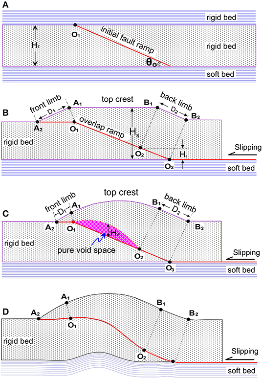
Figure 1. Schematic cross section of a pure fault detachment void space. (A) A rigid bed between two soft beds showing the location of a future fault. (B) A typical model of fault-bend fold. (C) Model showing the development of fault detachment void space in a fault-bend fold due to curvature of the hanging wall. (D) Example illustrating how concordant folding of both the footwall and hanging wall does not result in void space.
A model is set up for the description of pure fault detachment void in a single fault-ramp structure (Figure 1A). The main assumptions for this model are as follows: (1) Each bed maintains a uniform thickness and experiences no area or volume loss; (2) deformation occurs entirely by interbed slip; (3) there is no non-homogeneous shear between adjacent beds (Mitra and Nanson, 1989); and (4) the rigid bed has an initial planar fault ramp and is located in two soft beds. We assume that the pure rigid bed and/or geological rigid strata have a constant length, incompressible and inextensible by plastic deformation such as rearrangement or reconstruction of particles, but it is contractible and extendable by elastic deformation such as rearrangement of rock pieces.
Some geometrical parameters in Figure 1 were originally defined by the previous researchers, such as Suppe (1983) and Shaw et al. (1994), where θ0 is the ramp angle; Hr is the thickness of rigid rock; A1, A2 (for front limb) and B1, B2 (for back limb) are the axis-projected points on the top surface, respectively; D1 and D2 are the front and back slipping displacement, respectively. We here define that O1 and O2 are the upper and the lower onlap points on the ramp, respectively; the ramp section of O1 and O2 is called the overlap ramp, and L denotes its length; Hf is the fault throw; ΔD is the slip displacement consumed (John et al., 1994) in the fold; Hs is the stack thickness from the top crest to the bottom confined in the zone of overlap ramp; Hv is the height of pure void. These parameters satisfy the following relations (Figure 1):
For a purely rigid bed, a relative bigger-scale void would not be produced between two slipping thrust walls with the accommodation of strata at depth, as shown in Figure 1B (John et al., 1994). The height of the largest void we have observed in outcrops or subsurface drilling, which filled by calcite, was ~1 m (see the below as an outcrop case), but a restored “fault detachment void space” extracted from the fracture pores should exist between two translated walls (Figure 1C). In such a case, the top crest was arched (instead of a flat top crest in Figure 1B), the footwall maintains the original form on cross section, and there is no deformation on the in-line section; the stack thickness (Hs) is larger than the sum of throw and rock thickness (Hs > Hf + Hr); the front displacement is less than the back displacement (D1 < D2) because of the slip displacement consumed in the fold, and such displacement is closely related to the fault detachment voiding. This “fault detachment void space” can be derived from kinematic and geometrical analyses of fault-ramp structure, and it might be filled by foreign mechanical medium, or inner rock pieces combined with scattered fracture pores or a mixture of them during the stage of fault movement, so that the relationship between void space and fracture pore space on cross section can be written as:
where Sv(x) is the area of “void space,” Sm(x) is the void space occupied by foreign mechanical media, and Sf(x) represents the total fracture pore space in the fault zone. If there are not foreign mechanical media carried into this “fault detachment void,” then Equation (1) can be written as:
This implies that the “detachment void space” between two slipping walls is equal to the sum of fracture pore spaces in the fault zone. The “fault detachment void” does not exist in physical form on large scale, but its derived space does exist. It is substituted by the fracture pore space scattered in the fault-fractured zone, which here is named pure detachment void (or imagined equivalent detachment void), referring to the sum of the fracture pores by the way of extracting the pore space from the fault-fractured zone. Such a transform is an inverse restoration process for the pore space.
There are two possible ways of void formation in a fault-ramp structure: (1) bed surface detachment voiding and (2) fault surface detachment voiding (Figure 2). Bed surface voiding refers to the voiding between two rigid bed surfaces in the vicinity of the fault section where one wall is dragged by the other with friction resistance (Figure 2B). This fault drag involves rotational movement and may originate from a kind of “nail effect.” The nail here is a striking point or segment on the slipping fault section, which fixed the two translated blocks as a nail by the friction resistance. Other non-fixed beds would continuously move forward or backward and pull away from the nailed point or segment under the progressive push of the powerful tectonic pressure so that the bed surface detachment void was produced (Figure 2B). Each point on the fault section might be a nail. Bed surface void in a footwall is caused by forward friction resistance, which results in upward rotation, and by backward friction resistance, which results in downward rotation for the hanging wall.
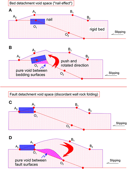
Figure 2. Schematic cross section showing the mechanics of pure fault detachment void space. (A,B) Bed surface detachment void space produced by a ramp nail and left expanding rotation; (C,D) ramp detachment void produced by a front nail and right expanding rotation of hanging wall.
Fault-ramp detachment voiding refers to the detachment void between two slip fault walls, which is caused by single discordant folding of hanging wall or footwall during fault slip (Figures 2C,D). The thrust front may be fixed relative to deforming, softer hanging wall beds (Figure 2C), causing the hanging wall to bend under a one-axial compressive stress. The continuous movement of the other free termination and bend body leads to a single arching of a hanging wall because the slipping between the two walls made it possible for the hanging wall to detach from the footwall. This generates an ideal fault detachment void space between the two walls (Figure 2D).
Therefore, the mechanism of fault-ramp detachment voiding is similar to that of the detachment void at the kink of a fold structure between two slipping bed surfaces formed by buckling; it is different from the bed surface detachment void beside the fault with the origin of fault dragging. However, both mechanisms were almost simultaneously substituted by smaller fracture pores with the accommodation of strata at depth, and it is difficult to distinguish these two void spaces in a present fault-ramp structure, which often occur at the same place.
Four typical patterns of pure detachment void are recognized on the basis of location and scale (Figure 3) (Nelson et al., 1999; Nelson, 2001). The properties of geometric parameters are defined in Table 1 (e.g., Nelson, 2001; Xu et al., 2006; Li et al., 2012; Choi et al., 2016; O'Hara et al., 2017; Liu et al., 2018).
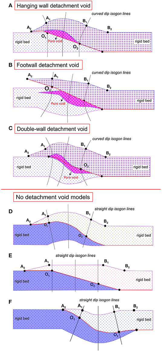
Figure 3. Schematic cross section showing typical kinds of pure fault detachment void space. (A) Pure void developed in hanging wall; (B) pure void space developed in footwall; (C) void space developed in both of the fault walls; (D–F) non-pure void space between two fault walls. Their properties are given in Table 1; the dip isogons lines within (A–C) are curved, but these are straight lines within (D–F).
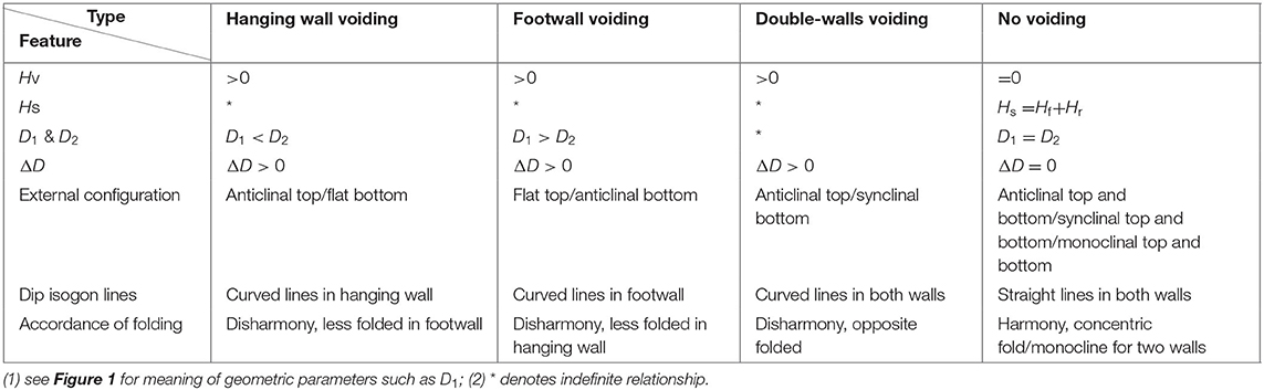
Table 1. Geometric parameters of single fault-ramp structure corresponding to Figure 3.
It is the most typical pattern. In this case, the hanging wall was considerably folded resulting in the form of a front-peak anticline or a double-peak anticline. The front peak (labeled as A1 in Figure 3) is usually above the upper overlap (labeled as O1 in Figure 3) and the back peak is often departure forward from B1 in Figure 3. The footwall maintains the original form or is slightly folded synchronously to the hanging wall (Figure 3A).
In this case, the footwall was downward arched and involved into a syncline, but the hanging wall kept the original form as a monocline. The void developed in the footwall. The geometric image of such a fault structure is an inverse image of a hanging wall voided fault-ramp structure (Figure 3B).
The pure detachment void might occur in both of the walls, which can be further divided into three styles: (1) symmetric double-wall detachment void, which is referred to a similar symmetric distribution of detachment void in which detachment voids occur at the core of inverse arched walls—it is a very rare case; (2) oblique symmetric double-wall detachment void, which is referred to an oblique symmetric development of void in which the hanging wall void occurs at the front (behind O1) and the footwall void is developed around O2; and (3) complex double-wall detachment void, which is referred to the distribution of detachment void that might occur at any places in the overlap ramp.
In this case, there is none or a very small detachment void developed between two walls (Figures 3D–F). It also has the three basic structure configuration types: (1) both of the walls deformed into anticline (Figure 3D); (2) both of the two walls deformed into syncline (inverted image of Figure 3F); and (3) both of the top and bottom walls show as monocline (see the details in Figure 1B).
The Daba Shan is located along the southern margin of the Qinling orogen, Central China (Liu et al., 2006; Dong et al., 2013, Shi et al., 2013; Figure 4A). Three main faults can be traced from north to south along the entire strike of the Daba Shan foreland thrust system as follows: (1) the Ankang fault (F1), (2) the Chengkou fault (F2), and (3) the Zhenba thrust (F3), respectively (e.g., Dong et al., 2013; Li et al., 2015; Figure 4A). The Chengkou fault is defined as the boundary between the Northern Daba Shan foreland thrust belt and the Southern Daba Shan foreland fold-and-thrust belt (Liu et al., 2006) (Figure 4A). The inferred Tiexi thrust fault (F4) to the south places at the boundary between the Southern Daba Shan and foreland Sichuan Basin (Liu et al., 2006) (Figure 4A). Our outcrop study areas are closed to the Tiexi thrust fault and Chengkou thrust fault (Figures 4A,B, 5A).
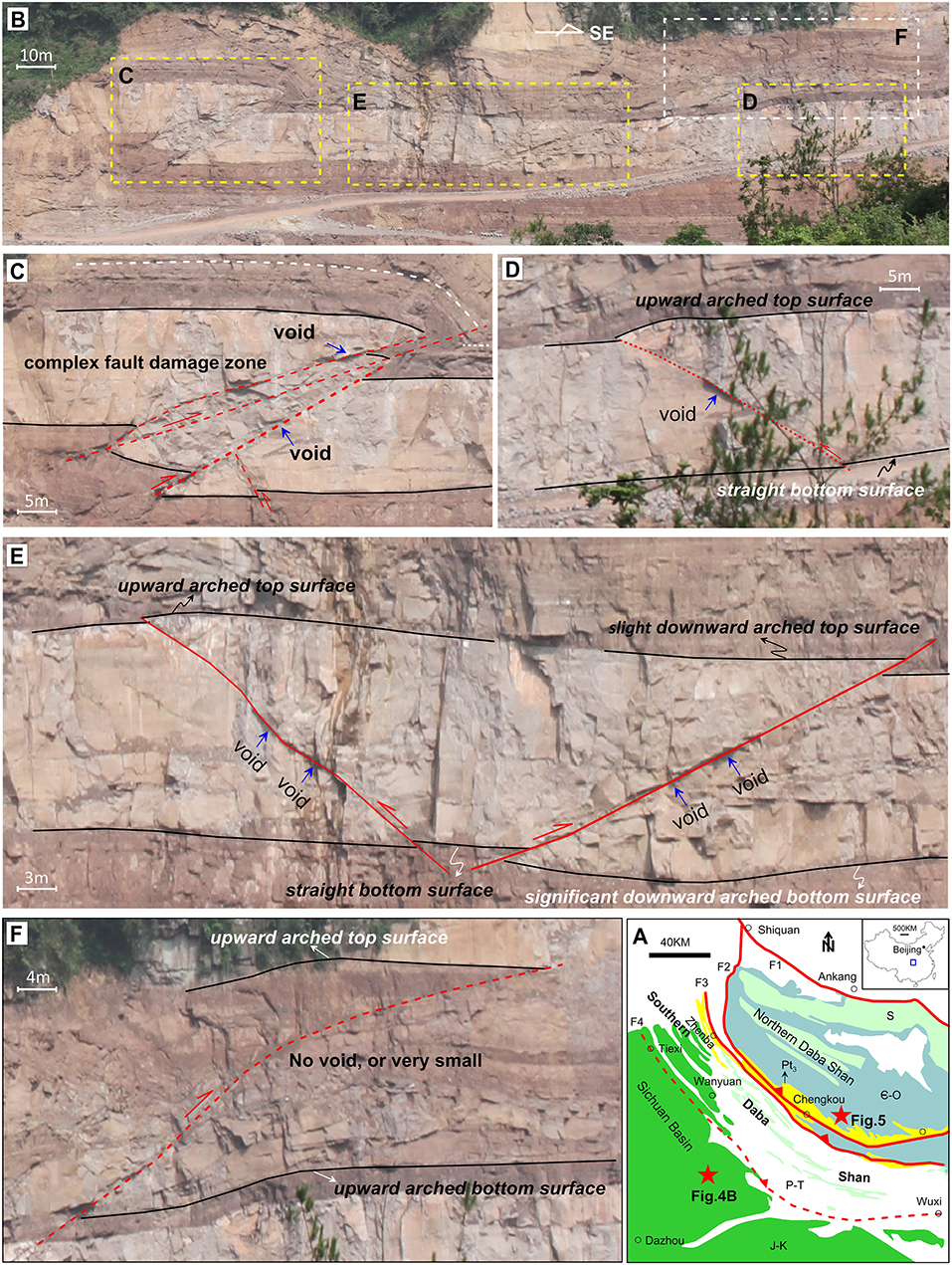
Figure 4. (A) A simple geological map shows the tectonics of the Daba Shan and Sichuan Basin, where the red lines represent the thrust fault and the red triangles point out the location of the hanging wall; the five-pointed stars show the outcrop location of (B) and Figure 5; note: Pt3–Neoproterozoic strata; ϵ-O—Cambrian–Ordovician strata; S—Silurian strata; P-T—Permian–Triassic strata; J-K—Jurassic–Cretaceous strata. (B–F) An outcrop case from the Sichuan foreland basin showing the fault fracture void space; see the details in the text. The blue arrows show the location of the possible void spaces.
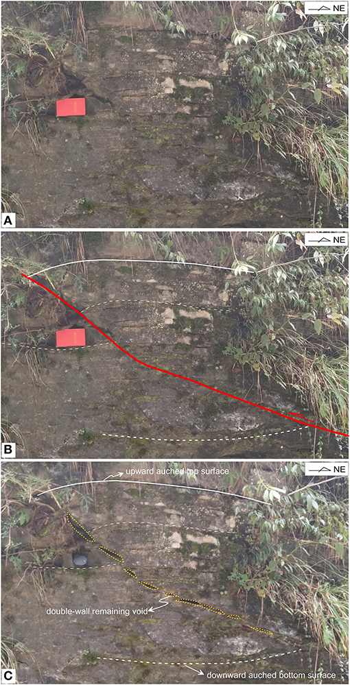
Figure 5. An outcrop case occurred within the Cambrian strata located in north of the Chengkou thrust fault in the Daba Shan foreland thrust belt (see Figure 4A for location). (A) Original photo; (B) Interpreted photo showing the geometries for fault and top and bottom surfaces of hanging-wall and footwall; (C) Interpreted photo showing the fault-related fracture system, note the yellow circles show the development of the possible void spaces.
The Jurassic sedimentary outcrop of Figure 4B is located at the south of the Tiexi thrust fault developed within the Sichuan Basin, which consists of gray sandstones and yellow-brown mudstones. Figure 4C shows the complex fault zone with multiple fracture surfaces, which suggests the existence of the possible remaining voids. The occurrence of the upward arched top surface with the straight and flat bottom surface in the hanging wall suggests the development of the void space (Figures 4D,E) as the model of Figures 1C, 3A. Although the top and bottom surfaces can be either downward or upward arched (Figures 4E,F), the presence of a void space depends on the curvature differences between the two surfaces. When the curvature of the arched bottom surface is greater than that of the arched top surface, the existence of void spaces is favored (Figure 4E). However, another fault shows no void, or very small voids, perhaps because the fault juxtaposes interbedded strong and weak layers that deform to remove potential void space (Figure 4F).
The outcrop shown in Figure 5 is located along the Chengkou thrust fault, 30 km east of Chengkou city (Figure 4A). The fault is developed within thin Cambrian limestone layers (Figure 5A). The top surface of the hanging wall shows the feature of upward arched, whereas the bottom surface of the footwall is downward arched (Figure 5B). We observe more than nine possible void spaces with different scales and shapes (Figure 5C) as the “double-wall remaining void” model of Figure 3C. We interpret that these observed discontinuity void spaces are consistent with the heterogeneity of fault fracture development (e.g., Xu et al., 2006). Void spaces appear to be larger on the hanging wall of this outcrop (Figure 5C), which may be related to lithologic variations and differential strain partitioning with the deforming wall rock during faulting.
Almost all broken rock surfaces, regardless of whether they are macroscale bedding surfaces or microscale lattice defect surfaces, can be the boundaries of fracture pores in a fault-fractured zone. The fractures in a complex fracture system may appear randomly, but they would be in order if we observe them with the idea of fracture sequence. The concept of fracture sequence is defined as a series of concessive listed fractures of a particular space configuration with the same or related origin and similar initial occurrence. For example, the parallel shear, radial joint, pinnate joint, and en-echelon cracks are the common patterns of fracture sequences. A complex fracture system often consists of many kinds of fracture sequences. Composition of fracture pores in the fault zone allows us to better understand the relationship between the fracture pores and the geometry of the thrust structure.
All the fracture pore space in a complex fracture system can be classified into two main fracture sequences (Dual composition, Figure 6), by merging all the bedding extended fracture pore components into the longitudinal fracture (joint) and the longitudinally extended fracture pore space into bedding fractures (Figures 6A-1, A-3, B-1, B-3). It has an equal effect on the entire fracture system in the quantitative estimation of fracture pore space.
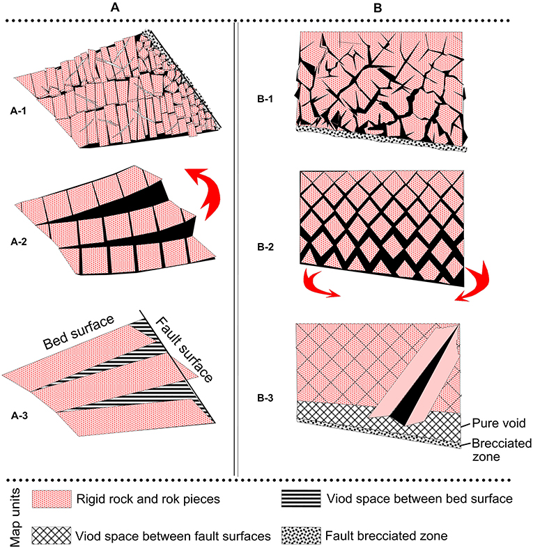
Figure 6. Schematic section showing the space exchange models for void space between bed surfaces (A) and void space between fault surfaces (B). The forward process: fracture pore space abstracted to pure fault detachment void space, which is (A-1)–(A-3) or (B-1)–(B-3), respectively; The inverse process is pure fault detachment void space distributed to the fracture, which is (A-3)–(A-1) or (B-3)–(B-1), respectively.
A model of fracture pore space framework is set up for linking the pure void space to the fracture pore space, as shown in Figure 6, which illustrates the forward and inverse transformations between fracture pore space and pure fault detachment void space. The forward transformation is the process of distributing the pure fault detachment void space into fracture pore space; the inverse transformation is the process of extracting the pure void space from the fracture pore space and recovery of strata.
Figure 6A-1 is an ideal model of fracture pore framework that originated by fault dragging during the bed surface detachment formation process (e.g., Figure 2B). Figure 6A-2 is the result of composed fracture sequence after processing of dual fracture sequence analysis. There are two separate main fracture sequences: the longitudinal and bedding fracture sequence. If all the fracture pore spaces are closed, then it should give a concentrated void space, which would be the bed surface detachment void space (Figure 6A-3). The void space can also be filled by the bedding fracture pores, together with rock pieces by the way of bedding extension, further substitution of void space is by the interfingering of panel-like rock pieces cut by fractures originated from fault friction and other fractures such as planar joints and shears.
Figure 6B shows a model of fracture pore space framework associated with fault-ramp detachment voiding (e.g., Figure 2D) under compressive stress. In this case, the pure void space is occupied by rock pieces together with fracture pore space by means of double-direction extending under the squeeze stress in inner arch of folded wall on the cross section. The term “double-direction extension” refers to the movement of square-like rock pieces cut by the two sets of shears in the inner arch of fold toward the other wall along each dip of the shear. The total fracture pore space can be further decomposed into two oblique fracture sequences (Figure 6B-2). These two pore-bearing oblique fracture sequences were derived from two sets of shears with the sharing of pure void space during the single folding of one wall. Otherwise, the inverse extraction process is that these fracture pore spaces can be transferred into pure fault detachment void spaces by the way of double-direction contraction.
Fracture porosity is the most direct and sensitive parameter for the description of fracture pore space. The decomposition of the fracture system gives out the individual fracture sequence, which is suitable for the quantitative calculation with the available geometrical parameters. We can obtain the equivalent fracture porosity for each point through the stack of components. Fracture porosity can be divided into two basic types: the longitudinal fracture porosity and the bedding fracture porosity. The former is already defined by Murray (1977), whereas the latter can be derived from the model given in Figure 6.
For a pure rigid stratum between two soft beds, the bulk longitudinal fracture porosity above the neutral surface for the fold structure on cross section is:
The longitudinal fracture porosity Fl(x) is a function of curvature (c) and the longitudinal distance between the top surface and the neutral surface (T) (Murray, 1977).
Figure 7 shows the parallel quadrilateral unit model for the estimation of fracture pore space, where the short side refers to the fault section and Δl1 is the initial length of fault segment, θ0 is the ramp angle (i.e., the initial angle between the bed and the fault surface), the long side refers to the bedding surface, and T denotes the fracture propagated length (Figure 7A), Δl2 is the fault segment length in the final stage, β1, β2 are the two final adjacent angles between the bed and fault plane beside the bedding fracture, θ denotes the finial fault dip, and Δβ is the fracture extending angle (Figure 7B). S1 is the void between the rotated rigid bed and the main fault surface, the area of fracture (Sf), initial area of unit (Sm) is defined as:
Since the area S1 is often filled by fault clay and to be brecciated, there is often no pore space developed area, and thus, S1 < < Sf. If we take S1=0, equation of Fz (x) can be rewritten as:
Let Rθ = Δβ/Δx2, then
Since Δl1 ≤ Δl2 ≤ Δl1 + Δβ·T; Δβ < < Δl1, then Δl1 ≈ Δl2, we have:
where α, θ, β are the bed dip, fault dip, and the angle between bed and fault plane on the cross section of x-axial, respectively.
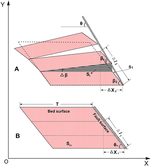
Figure 7. Schematic model for calculating the bedding fracture pore space. (A) Void space occurred between bed surfaces. (B) Initial model with no void space.
As shown in Equation (6), the bedding fracture porosity is a function of the derivation of the angle between bed and fault plane (Rθ), the fracture propagated length (T), initial and final fault dips (θ1, θ2), and ramp angle (θ). Rθ is the most dominant parameter controlling the development of bedding fracture pore space, just as the curvature in controlling the development of longitudinal fracture pore space.
For model 1 (Figure 6), on the basis of stacking rule, the fracture porosity (F(x,z)) is:
For model 2 (Figure 7), Equations (5) and (6) are also valid for the calculation of fracture pore space. On the basis of stacking rule, the only difference between these two models is that θ2 in model 2 denotes the angle between the shear and the fault plane. The space transform models illustrate that the pure void space is a kind of longitudinally extended pore space and it could be entirely substituted by the bedding fracture pore space. The longitudinal fracture pore space does not seem to take part in the sharing of the pure void space based on our observation; therefore,
Since in the initial stage of void space development, the opportunities for developing longitudinal fracture pore space are few because the strata is located at the inner arch of a contracted zone. Large amounts of fractures in this case are the shear, bedding fractures, and shallow fissures. Slight movement or fracture of rock pieces toward the pure void space was often completed by the longitudinal extension of bedding fractures and low dip fractures. Subsequently, this movement of the pure void space also gives a space for the bedding extension of longitudinal fracture and other high dip fractures or cracks, no matter the initial state void space sharing involved fractures is open or closed. Hence, we integrated all the pore spaces into the bedding fractures or oblique fractures in order to investigate the distribution of fracture pore space with the available geometrical parameters.
From Equation (6), we know that the change rate of angle between fault and bed (Rθ), fracture propagated length (T), initial and final fault dips (θ1, θ2), and ramp angle (θ) are the main geometrical parameters that control the fault fracture pore space. Below, we discuss these parameters.
The geometrical meaning of Rθ can be expressed by the curvature of dip isogons (as illustrated in Figure 3), and defined as the indicator of conformity between two fault sections or the accordance of folding between the two opposite walls. The geological and geometric means can be expressed clearly using dip profile (Bengtson, 1982). Figure 8 indicates that the dips of bed and fault surfaces are the functions of horizontal distance along the line of fault plane on cross section. All the dip lines are smoothed. The relationships between Hv and Fz (x,z) in particular cases of fault-ramp structure are as follows:
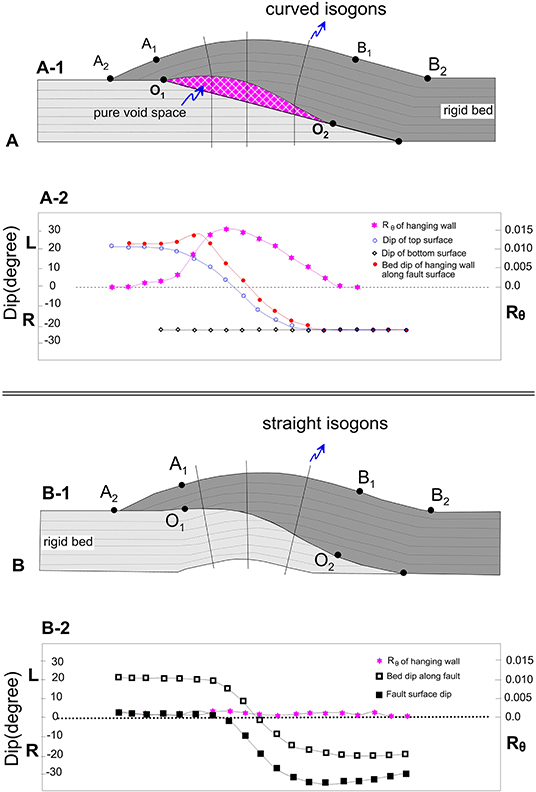
Figure 8. Diagram showing the geological and geometry means of the derivation of angle between fault and bed plane to the horizontal distance. (A) Model with curved isogon lines suggesting well-developed fault detachment space; (B) Model with straight isogon lines suggesting none fault detachment space.
This is the most typical example of hanging wall fracture pore space (or pure void space) (Figure 8A), where we assume that the top crest is arched and the footwall maintains the primitive form. We have:
hence Rθ > 0; Fz(x, z) > 0
Therefore, in this case, the pure void space or the fault fracture pore space is the result of disharmonic folding of two fault walls.
There is no pure void space or fault fracture pore space between two translated blocks (as illustrated in Figure 8B), or the void produced by the hanging wall was completely filled by the footwall because both of the walls folded discordantly, which implies that:
Therefore, Fz(x,z) = 0.
Hence, the fold structure displays a concentric folding between two walls, and the dip isogons are displayed as straight lines.
From the discussion above, we suggest that the geometrical meaning of Rθ is expressed by the curved degree of isogons, and its geological meaning reflects the folding accordance of two walls.
The bedding fracture-propagated length (T) depends on many factors, which include the elastic properties, the thickness of strata between two slipping planes, and the structural stress and energy. Similar to longitudinal fracture-propagated length, it depends more on the thickness of rigid strata between two slipping surfaces than any other external factors.
The relationship between the ramp angle and the fracture porosity based on Equation (6) indicates that the ramp angle is inversely proportional to the fracture porosity. The smaller the ramp angle is, the larger the fracture porosity will be. That is, a low-angle fault has the potential to produce larger fracture porosity.
For a fault-ramp structure developed within rigid strata, pure void space is predicted to form along the fault depending on the relative curvature of the hanging wall and footwall wall rock. This void space equals the sum of fracture pore space and filled-in void space around the fault zone; we herein quantify this void space assuming simple area balance. Two basic models of deformation were established: (1) bed surface detachment and (2) fault-surface detachment void space. The first involves dragging of the bedded strata to produce fracture pore space, whereas the second involves detachment of the fault surface from folded wall rock to produce void space. The development and distribution of pure fault detachment void or fault fracture pores are controlled by physical conditions, mechanics of deformation, and the geometry of the fault-ramp structure. The degree of discordance between the hanging wall and the footwall along a single fault plane influences the geometry of this void space.
Our model to qualify void space involves the following parameters, including initial ramp angle (θ0) and height (Hr), overlap ramp length (L), throw (Hf) and slipping displacement (D1, D2), stack thickness (Hs), curvature and derivation of the angle between bed and fault plane (Rθ), and dip isogons. For a constant ramp angle and height and rigidity, the most important prerequisites for fracture pores developing fault segment are (1) L > 0 and (2) Rθ > 0. The ramp angle also plays an important role in fracture porosity, and an inverse relationship between angle and pore space is predicted.
The derivation of angle between the fault and the bed to distance reflects the conformity of two opposite fault sections and the folding accordance of two walls. Just like the curvature for controlling longitudinal fracture pore in the external arch, it is a key element for the development and distribution of fracture pore space in the fault zone.
The original contributions presented in the study are included in the article/supplementary material, further inquiries can be directed to the corresponding author/s.
XL: conceptualization, investigation, model building, writing—original draft, outcrop examples, and funding acquisition. GX: conceptualization, investigation, model building, writing—original draft, supervision, and project administration. CW: conceptualization, investigation, writing—original draft, visualization, and funding acquisition. AY: investigation, improve model, supervision, and writing—review and editing. SW and GC: formula derivation and mathematical modeling. AZ, SX, and YL: investigation and writing—review and editing. ZL: outcrop examples and writing—review.
This research was financially supported by the PetroChina Innovation Foundation (2016D-5007-0107); the Natural Science Foundation of Chongqing, China (cstc2020jcyj-msxmX0487); the Open Fund (PLC2020020) of State Key Laboratory of Oil and Gas Reservoir Geology and Exploitation (Chengdu University of Technology); and the Basic Science Center for Tibetan Plateau Earth System (CTPES, Grant No. 41988101-01). This work was also supported by the National Science Foundation of China (Grant No. 41702232). The funders were not involved in the study design, collection, analysis, interpretation of data, the writing of this article, or the decision to submit it for publication.
SW was employed by the Exploration and Development Research Institute of Southwest Oil and Gasfield, PetroChina.
The remaining authors declare that the research was conducted in the absence of any commercial or financial relationships that could be construed as a potential conflict of interest.
Aarland, R. K., and Skjerven, J. (1998). Fault and fracture characteristics of a major fault zone in the northern North Sea: analysis of 3D seismic and oriented cores in the Brage Field. (Block 31/4). Geol. Soc. London Spec. Public. 127, 209–229. doi: 10.1144/GSL.SP.1998.127.01.15
Aydin, A. (2000). Fractures, faults and hydrocarbon entrapment, migration and flow. Mar. Petrol. Geol. 17, 797–814. doi: 10.1016/S0264-8172(00)00020-9
Beach, A., Welbon, A. I., Brockbank, P. J., and McCallum, J. E. (1999). Reservoir damage around faults: outcrop examples from the Suez Rift. Petrol. Geosci. 5, 109–116. doi: 10.1144/petgeo.5.2.109
Bengtson, C. A. (1982). Structural and Stratigraphic Uses of Dip Profiles in Petroleum Exploration. Tulsa: American Association of Petroleum Geologists.
Caine, J. S., Evans, J. P., and Forster, C. B. (1996). Fault zone architecture and permeability structure. Geology 24, 1025–10282. doi: 10.1130/0091-7613(1996)024<1025:FZAAPS>2.3.CO;2
Choi, J. H., Edwards, P., Ko, K., and Kim, Y. S. (2016). Definition and classification of fault damage zones: a review and a new methodological approach. Earth-Science Rev. 152, 70–87. doi: 10.1016/j.earscirev.2015.11.006
Dong, S. W., Gao, R., Yin, A., Guo, T. L., Zhang, Y. Q., Hu, J. M., et al. (2013). What drove continued continent-continent convergence after ocean closure? Insights from high-resolution seismic-reflection profiling across the Daba Shan in central China. Geology 41, 671–674. doi: 10.1130/G34161.1
Feng, J., Ren, Q., and Xu, K. (2018). Quantitative prediction of fracture distribution using geomechanical method within Kuqa Depression, Tarim Basin, NW China. J. Petrol. Sci. Eng. 162, 22–34. doi: 10.1016/j.petrol.2017.12.006
Gross, M. R., Fischer, M. P., Engelder, T., and Greenfield, R. J. (1995). Factors controlling joint spacing in interbedded sedimentary rocks: interpreting numerical models with field observations from the Monterey Formation, USA, Fractography: fracture Topography as a Tool in Fracture Mechanics and Stress Analysis. Geol. Soc. Am. Spec. Public. 92, 215–233. doi: 10.1144/GSL.SP.1995.092.01.12
Howard, J. H. (1990). Description of Natural fracture systems for Quantitative Use in Petroleum Geology. AAPG Bull. 74–2: 151–162. doi: 10.1306/0C9B2281-1710-11D7-8645000102C1865D
Huang, R. Q., and Li, W. L. (2009). Fault effect analysis of Geo-Hazard triggered by Wenchuan Earthquake. J. Eng. Geol. 17, 19–28. doi: 10.3969/j.issn.1004-9665.2009.01.003
Kim, Y. S., Peacock, D. C. P., and Sanderson, D. J. (2004). Fault damage zones. J. Struct. Geol. 26, 503–517. doi: 10.1016/j.jsg.2003.08.002
Li, J., Dong, S., Yin, A., Zhang, Y., and Shi, W. (2015). Mesozoic tectonic evolution of the Daba Shan Thrust Belt in the southern Qinling orogen, central China: Constraints from surface geology and reflection seismology. Tectonics 34, 1545–1575. doi: 10.1002/2014TC003813
Li, X. G., Xu, G. Q., Han, J. F., Shen, Z. M., Wu, S. H., Luo, C. S., et al. (2012). Application of a new method for quantitative calculation of fault-related fracture: A case study from Lianglitage Formation in Tazhong X Well Area, Tarim Basin, China. J. Jilin Univer. Earth Sci. Edition. 42, 344–352. doi: 10.3969/j.issn.1671-5888.2012.02.008 (in Chinese)
Liu, J. S., Ding, W. L., Dai, J. S., Gu, Y., Yang, H. M., and Sun, B. (2018). Quantitative multiparameter prediction of fault-related fractures: a case study of the second member of the Funing Formation in the Jinhu Sag, Subei Basin. Petrol. Sci. 15, 20–35. doi: 10.1007/s12182-018-0240-3
Liu, S. G., Li, Z. W., and Liu, S. (2006). Formation and Evolution of Dabashan Foreland Basin and Fold and-Thrust Belt, Sichuan, China. Beijing: Geological Publishing House, 248.
Mitra, S., and Nanson, J. (1989). Equal-area balance. Am. J. Sci. 289, 563–599. doi: 10.2475/ajs.289.5.563
Murray, G. H. (1977). Quantitative Fracture Study, Sanish Pool, Fracture Controlled Production. AAPG Bulletin Reprint Series, 21.
Nelson, E. P., Kullman, A. J., and Gardner, M. H. (1999). “Fault-fracture networks and related fluid flow and sealing, Brushy Canyon Formation, West Texas,” In Faults and Subsurface Fluid Flow in the Shallow Crust Geophysical Monograph 113, eds L. B. Goodwin, P. S. Mozley, J. M. Moore, W. C. Haneberg (Washington: American Geophysical Union), 69–81. doi: 10.1029/GM113p0069
Nelson, R. A. (2001). Geologic Analysis of Naturally Fractured Reservoirs, Second Edition. Boston, MA: Gulf Professional Publishing, 332. doi: 10.1016/B978-088415317-7/50004-X
O'Hara, A. P., Jacobi, R. D., and Sheets, H. D. (2017). Predicting the width and average fracture frequency of damage zones using a partial least squares statistical analysis: implications for fault zone development. J. Struct. Geol. 38, 38–52. doi: 10.1016/j.jsg.2017.03.008
Peacock, D. C. P., Dimmen, V., Rotevatn, A., and Sanderson, D. J. (2017). A broader classification of damage zones. J. Struct. Geol. 102, 179–192. doi: 10.1016/j.jsg.2017.08.004
Reyer, D., Bauer, J. F., and Philipp, S. L. (2012). Fracture systems in normal fault zones crosscutting sedimentary rocks, Northwest German Basin. J. Struct. Geol. 45, 38–51. doi: 10.1016/j.jsg.2012.06.002
Scholz, C. H. (2002). The Mechanics of Earthquakes and Faulting. Cambridge: Cambridge University Press. doi: 10.1017/CBO9780511818516
Shaw, J. H., Hook, S. C., and Suppe, J. (1994). Structural trend analysis by axial surface mapping. AAPG Bull. 78, 700–721. doi: 10.1306/A25FE38D-171B-11D7-8645000102C1865D
Shi, W., Wu, H. L., Dong, S. W., and Tian, M. (2013). Oil/gas migration and aggregation in intra-continental orogen based on numerical simulation: a case study from the Dabashan Orocline, Central China. J. Earth Sci. 24, 254–261. doi: 10.1007/s12583-013-0326-1
Smart, K. J., Ferrill, D. A., and Morris, A. P. (2009). Impact of interlayer slip on fracture prediction from geomechanical models of fault-related folds. AAPG Bull. 93, 1447–1458. doi: 10.1306/05110909034
Suppe, J. (1983). Geometry and kinematics of fault-bend folding. Am. J. Sci. 275-A, 684–721. doi: 10.2475/ajs.283.7.684
Walsh, J. J., and Watterson, J. (1988). Analysis of the relationship between the displacements and dimensions of faults. J. Struct. Geol. 10, 239–247. doi: 10.1016/0191-8141(88)90057-0
Keywords: pure fault detachment void space, fracture pore space, fault fractured zone, quantitative description, fault-related fracture porosity, derivation of angle between bed and fault plane
Citation: Li X, Xu G, Wu C, Yin A, Wu S, Zuza AV, Chen G, Li Z, Xu S and Li Y (2021) Pure Void Space and Fracture Pore Space in Fault-Fractured Zones. Front. Earth Sci. 9:683439. doi: 10.3389/feart.2021.683439
Received: 21 March 2021; Accepted: 22 April 2021;
Published: 13 May 2021.
Edited by:
Derek Keir, University of Southampton, United KingdomReviewed by:
Junpeng Wang, China University of Geosciences Wuhan, ChinaCopyright © 2021 Li, Xu, Wu, Yin, Wu, Zuza, Chen, Li, Xu and Li. This is an open-access article distributed under the terms of the Creative Commons Attribution License (CC BY). The use, distribution or reproduction in other forums is permitted, provided the original author(s) and the copyright owner(s) are credited and that the original publication in this journal is cited, in accordance with accepted academic practice. No use, distribution or reproduction is permitted which does not comply with these terms.
*Correspondence: Xiaogang Li, eGdfbGVlQGNxdXN0LmVkdS5jbg==; Guoqiang Xu, eHV1Z3EwQDE2My5jb20=
Disclaimer: All claims expressed in this article are solely those of the authors and do not necessarily represent those of their affiliated organizations, or those of the publisher, the editors and the reviewers. Any product that may be evaluated in this article or claim that may be made by its manufacturer is not guaranteed or endorsed by the publisher.
Research integrity at Frontiers
Learn more about the work of our research integrity team to safeguard the quality of each article we publish.