- 1Geophysical Engineering Department, Faculty of Mining and Petroleum Engineering, Institut Teknologi Bandung, Bandung, Indonesia
- 2Center for Geological Survey, Geological Agency of Indonesia, Ministry of Energy and Mineral Resources, Bandung, Indonesia
- 3Global Geophysics Research Group, Faculty of Mining and Petroleum Engineering, Institut Teknologi Bandung, Bandung, Indonesia
- 4Center for Earthquake Science and Technology (CEST), Research Center for Disaster Mitigation, Institut Teknologi Bandung, Bandung, Indonesia
- 5Exploration and Engineering Seismology Research Group, Faculty of Mining and Petroleum Engineering, Institut Teknologi Bandung, Bandung, Indonesia
The Banyumas Basin is a tertiary sedimentary basin located in southern Central Java, Indonesia. Due to the presence of volcanic deposits, 2-D seismic reflection methods cannot provide a good estimation of the sediment thickness and the subsurface geology structure in this area. In this study, the passive seismic tomography (PST) method was applied to image the 3-D subsurface Vp, Vs, and Vp/Vs ratio. We used 70 seismograph borehole stations with a recording duration of 177 days. A total of 354 events with 9, 370 P and 9, 368 S phases were used as input for tomographic inversion. The checkshot data of a 4, 400-meter deep exploration well (Jati-1) located within the seismic network were used to constrain the shallow crustal layer of the initial 1-D velocity model. The model resolution of the tomographic inversions was assessed using the checkerboard resolution test (CRT), the diagonal resolution element (DRE), and the derivative weight sum (DWS). Using the obtained Vp, Vs, and Vp/Vs ratio, we were able to sharpen details of the geological structures within the basin from previous geological studies, and a fault could be well-imaged at a depth of 4 km. We interpreted this as the main dextral strike-slip fault that controls the pull apart process of the Banyumas Basin. The thickness of the sediment layers, as well as its layering, were also could be well determined. We found prominent features of the velocity contrast that aligned very well with the boundary between the Halang and Rambatan formations as observed in the Jati-1 well data. Furthermore, an anticline structure, which is a potential structural trap for the petroleum system in the Banyumas Basin, was also well imaged. This was made possible due to the dense borehole seismographic stations which were deployed in the study area.
Introduction
Based on the sedimentary basin map of Indonesia (Indonesia Geology Agency, 2009), there are at least 13 sedimentary basins on Java Island; eight of these are categorized as intermontane arc basins and are located in the southern part of Java Island. These eight basins, located in the Java volcanic arc, are covered by Paleogene to recent volcaniclastic sediments; the presence of volcaniclastics causes poor quality data in the 2-D seismic reflection method, which is used to determine the subvolcanic sediment.
Our study area, the Banyumas Basin, is located in the southern part of the Central Java Province, Indonesia, and is one of intermontane arc basins covered by volcaniclastic sediment. Lack of geologic and geophysics (G&G) studies in the Banyumas Basin make it terra incognita in terms of petroleum exploration (Satyana, 2015). More specifically, the Banyumas Basin is located between the Gabon Fault in the western area and the Kebumen–Bantul Basin in the eastern area (Figure 1). Most of the area of the Banyumas Basin is located onshore as only a small part of the basin is located in offshore areas (Muchsin et al., 2002; Armandita et al., 2009; Indonesia Geology Agency, 2009; Satyana, 2015).
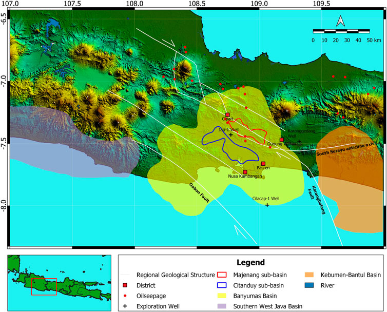
FIGURE 1. Map of the regional geological structure and the Banyumas Basin boundary (modified from the Geology Agency., 2009; Muchsin et al., 2002; Armandita et al., 2009; Satyana, 2015; Lunt et al., 2009; Hidayat et al., 2020).
Integrated geology and geophysics studies around the Banyumas Basin were performed by the Center of Geological Survey (CGS) under the Ministry of Energy and Mineral Resources of Indonesia in 2018 (Hidayat et al., 2020; Junursyah et al., 2019; Handyarso and Hidayat, 2019; Setiawan, 2019). These studies show that the Banyumas Basin consists of two subbasins (Lunt et al., 2009; Hidayat et al., 2020), that is, the Citanduy Subbasin in the southwestern part of the anticline structure, which is aligned in a NW–SE direction, and the Majenang Subbasin, which is northeast of the anticline.
The Banyumas Basin is also categorized as a tertiary sedimentary basin with hydrocarbon potential, based on discoveries of hydrocarbon seepage; some of these seepage discoveries were sampled for geochemical analysis. The biomarker characteristics suggest that oil seepage in the Banyumas Basin is derived from a deltaic fluvial depositional environment deposited in the Late Cretaceous to Eocene eras (Junursyah et al., 2019; Setiawan, 2019). However, an Eocene rock outcrop could not be found in our study area, which could be sampled for further analysis. Exploration using the 2-D seismic reflection method was also carried out to image the potential hydrocarbon reservoir and the geological structure as the source and migration path of the seepage. However, the obtained resolution was quite low due to the fact that the Banyumas Basin is covered by thick volcanic sediments. Based on the previous study in the Jati-1 exploration well, the volcanic sediments were still could be identified to a depth of 4, 000 m (Tampubolon et al., 2014).
To image the presence of geological structures and determine the thickness of sediment covered by volcanic sediments, we applied the passive seismic tomography (PST) method to the first PST survey with dense borehole seismographic stations in the Banyumas Basin. PST has been widely used in the hydrocarbon industry to investigate geological structures (Maxwell and Urbancic, 2001), fluid movement (Rutledge et al., 1998), and hydraulic fracturing (Rutledge and Phillips, 2003). A previous PST study in hydrocarbon-rich areas in southern Albania (Tselentis et al., 2011) shows a correlation between Vp structure anomalies and geological structures in the study area as well as Vp/Vs anomalies that reveal a correlation with fluid content in reservoirs (Hamada, 2004; Tselentis et al., 2011). The 3-D PST was also successfully carried out in regional explorations of hydrocarbon at a relatively low cost when compared to the 2-D seismic reflection method (Durham, 2003; Kapotas et al., 2003; Martakis et al., 2003; Martakis et al., 2006; Tselentis et al., 2007). This has led to the growing popularity of PST for use as a method of hydrocarbon exploration.
In this study, we determine the Vp, Vs, and Vp/Vs ratio using a local borehole network. A dense seismographic network of 70 borehole stations was deployed for about six months to record seismicity in the study area. To improve the signal-to-noise ratio of the recorded waveform, each borehole station was installed at the bedrock (around 12 m depth). Furthermore, a deep exploration well of ∼4.5 km depth was used to constrain the velocity structure obtained from the tomographic inversion. One of our objectives in this study was to delineate the geological structure, such as anticline, which is the most common structural trap for petroleum systems. A previous study (Purwasatriya et al., 2019) mentions that claystone from the Halang Formation could be a potential caprock for the Banyumas Basin petroleum system. According to the checkshot data from the Jati-1 well, the Halang Formation has the most significant velocity contrast (around 9.4%), compared to the Rambatan Formation, which was deposited below the Halang Formation. Based on the velocity contrast of these two formations, we attempt to delineate the subsurface geological structure of our study area.
Geology
From the aspect of the regional geological structure, the Banyumas Basin runs in three main structures. First, the Gabon strike-slip fault, which is in a northwest-southeast direction. Second, the Karangbolong strike-slip fault, in a northwest-southeast direction and represented by fault and folds structure. Third, the direction of the South Serayu geanticline, which consists of disturbed zones and the west–east trending geanticline (Pulunggono and Martodjojo, 1994) (Figure 1).
Figure 2A shows a regional geology map of the area around the Banyumas Basin. The oldest outcrop is the Gabon Volcanic Formation (Tomg), which is an Oligocene–Middle Miocene volcanic sequence found in the southwestern part of our study area. This is followed by the deposition of the Pemali Formation (Tmp), which consists of Lower–Middle Miocene turbidite deposits. Next is the Rambatan Formation (Tmr), which was deposited in the Middle Miocene and consists of limestone, sandstone, and conglomerates. Then follows the Kalipucang Formation (Tmk), which consists of Middle Miocene limestone; this is followed by the Halang Formation (Tmhs), which consists of napal and sandstone and are Middle Miocene–Early Pliocene turbidite deposits. The Kumbang Formation (Tmpk), which consists of sandstone breccias, is volcanic facies deposited in the Middle Pliocene era. Furthermore, the Tapak Formation (Tpt) is a sandstone intercalation of calcarenite with marl deposited in the Middle Pliocene–Late Pliocene; and finally, the volcanic and basalt of the Quaternary volcanic facies (Qa) (Setiawan, 2019). Based on the results of a previous geological study (Purwasatriya et al., 2019), reservoir rocks in the Banyumas Basin have their own unique characteristics because they are deposited in the volcanic environment. However, the presence of tectonic episodes during the Pliocene–Pleistocene period has made secondary porosity in the reservoir rocks, so that volcanic rocks in the Banyumas Basin area remain potential as reservoir rocks. Caprocks, which consists of volcanic rock and has low porosity and permeability, can be found as clay, silt, tuff, and marl in the Gabon and Halang formations. Potential trapping mechanisms in the Banyumas Basin can be structural traps, such as fault structures or anticline, and can also be statigraphic traps, such as reef and onlap. Based on a biomarker analysis, source rock for the Banyumas Basin is considered to have been generated from sediment deposited in the deltaic fluvial environment in the Late Crestaceous–Eocene period (Junursyah et al., 2019; Setiawan, 2019); this criterion is suitable for the black shale found in the Eocene sediment in the Karangsambung Formation.
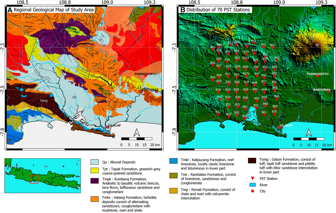
FIGURE 2. (A) Regional geological map of the study area (modified from Budhitrisna, 1986; Supriatna et al., 1992; Kastowo, 1975; Simandjuntak and Surono, 1992; Djuri et al., 1996; Asikin et al., 1992) and (B) distribution of PST stations shown by red-colored inverted triangle.
Seismic Network and Data
In this study, we used passive seismic data acquired from the Ministry of Energy and Mineral Resources of the Republic of Indonesia through the Geological Survey Center. Data acquisition consisted of 70 recording stations (Figure 2B), which had a recording duration of approximately 177 days, starting from March 17 to September 9, 2018, using broadband, three-component borehole Geobit, and SRI23 seismographs. The seismometer sensor used is a borehole type that was installed at an average depth of 12 m at each station. Each seismograph station is equipped with coordinates and elevation measurements using the differential global positioning system (DGPS) to obtain an accurate position at each recording station. For tomographic inversion, the waveform used in this study is a local and regional event with arrival time differences for S and P waves (ts−tp) less than 25 s (Supplementary Figures S1, S2). We determine seismograph stations deployment based on seismic activity and coverage of some geological features that are potential hydrocarbon traps, considered by previous studies on the regional geological and geophysical features, such as gravity, 2-D seismic reflection, and exploration wells. We also used these studies to validate our tomographic results. Several geological features, such as the Cipari anticline trend, the dextral strike-slip of the Pamanukan–Cilacap Fault, and the oil seepage around our seismograph stations, were used for validation in our horizontal and vertical cross section. Lithologically, this seismic network was also designed to cover rock units ranging from the Gabon Formation (Tomg), deposited during the Oligocene–Miocene, to the surficial deposits (Qa). The average distance that was applied between each seismic station was about 5–6 km in order to cover about 60 × 25 km of the study area (Figure 2B).
The result of travel time tomography inversion is expected to image the condition of the geological structures related to the generation of the pull apart basin, as well as the trapping mechanism for the petroleum system in this study area.
Data Processing
Picking P and S Wave Phase and Hypocenter Location Determination
The event identification and picking process of P and S waves’ arrival times are done manually by eye using SeisGram2K software (Lomax and Michelini, 2009). In this study, we only used events that have a difference in arrival times of P and S less than 25 s. A total of 354 earthquake events were used in this study, with 9,370 P wave phases and 9,368 S wave phases. The quality control (QC) of the picking process for all events is performed using a Wadati diagram, as shown by example in Supplementary Figure S2.
Determining the Hypocenter Location with the NonLinloc Method
We determined the hypocenter locations using a nonlinear method from the NonLinLoc program (Lomax, 2008) with an inversion approach that relies on the use of PDF normalization and non-normalization to demonstrate our knowledge of parameter values (Tarantola and Valette, 1982). The algorithm used in the inversion process for determining the location of hypocenter is the oct-tree importance sampling, which uses a recursive division process. First, a large grid is divided into the sample space, then the PDF value for each cell is calculated, and finally, the PDF value is entered into the PDF list. The largest PDF value is then retrieved from the list, the cells in the largest PDF value are subdivided again, and the PDF value is calculated. The procedure is repeated until the number of cells is determined, and a solution for the location of the earthquake is found. To determine the position of the hypocenter using the NonLinLoc program (Lomax et al., 2000), in addition to using the P and S wave arrival time data, some additional information, such as the position of the PST station coordinates and the 1-D velocity model was also required. The 1-D velocity model used in this study (Figure 3 and Supplementary Table S1) is a combination of Jati-1 well checkshot data for the shallow crust and the results of a travel time tomography study done in south Central Java (Koulakov et al., 2007) for the deeper crust. The Jati-1 well is the deepest exploration well located within our seismic network. The distribution of 354 seismic events is shown in Supplementary Figure S4.
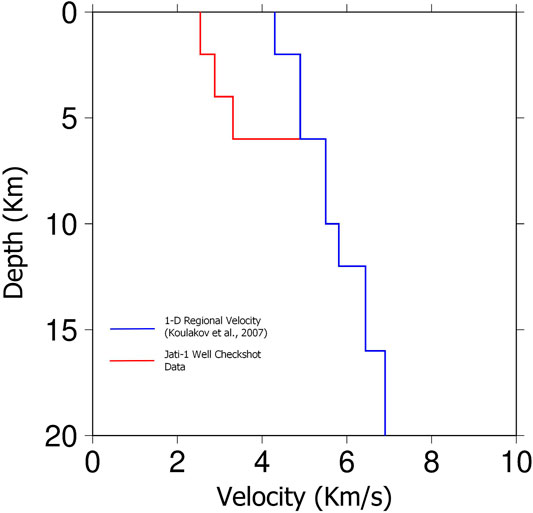
FIGURE 3. Comparison of top 20 km regional 1-D velocity (Koulakov et al., 2007) and local 1-D velocity using Jati-1 well checkshot data to specify a layered model or a 3-D velocity model. Jati-1 well checkshot data give a more detailed velocity contrast on the shallow crust. We used 1.74 as initial Vp/Vs ratio value for tomography inversion. The complete 1-D initial velocity model which we used in this study is shown in Supplementary Table S1.
Travel Time Tomography Inversion to Determine 3-D Vp, Vs, and Vp/Vs Ratio
We applied the SIMULPS12 program (Evans et al., 1994) to determine the 3-D Vp and Vp/Vs ratio structure with simultaneous hypocenter adjustment (Eberhart-Phillips, 1986; Thurber, 1993; Thurber, 1993). The inversion method used a damped least square, which simultaneously calculates the velocity model and relocates hypocenters. The ray path parameters in the 3-D velocity structure were obtained from calculations using the pseudo-bending ray tracing method (Supplementary Figure S5) (Um and Thurber, 1987).
Some input parameters for travel time tomography inversion for the determination of the 3-D Vp, Vs, and Vp/Vs ratio are: arrival time of the P and S wave, the initial seismic velocity model, hypocenter location, and location of the PST station. The initial model for hypocenter parameters was obtained using the NonLinLoc program. The initial velocity model used for Vp is mentioned in Figure 3 and Table S1, while we used Vp/Vs of 1.74; which is obtained by using a modified Wadati diagram in Supplementary Figure S3, as an input for tomographic inversion, which was then updated using an inversion algorithm from SIMULPS12. The application of checkshot data is meant to specify a more detailed and a local 1-D velocity model in order to delineate geological features at shallow depths. Supplementary Figure S6 shows histogram of travel time residual (in seconds) of P and S wave phases decreased after the tomographic inversion and how RMS residual decrease by number of iteration.
The initial 3-D velocity model was created in a grid node with a cell size of 5km x 5km x 2km. Each cell in the grid node contained initial velocity model information, which was then used in the tomography inversion. A damping parameter is needed to stabilize solutions in tomography inversion. The optimum value of the damping parameter is obtained from the comparison of variance data with the variance model on the trade-off curve (Supplementary Figure S7). In this study, the optimum damping value for both Vp and Vp/Vs is 40. The optimum damping value varies with the amount and distribution of data, size, and distance from the grid nodes (Eberhart-Phillips, 1986).
Resolution Test
A resolution test was performed using the checkerboard resolution test (CRT), the diagonal resolution element (DRE), and the derivative weight sum (DWS), using a grid node with the same cell size, which we used for tomography inversion; as mentioned in Section Travel Time Tomography Inversion to Determine 3-D Vp, Vs, and Vp/Vs Ratio. CRT was performed by making a synthetic velocity model, giving high and low perturbation of ±10% to the initial model. The value of ±10% perturbation was set based on the Halang–Rambatan formations’ velocity contrast (around 9.4% as mentioned in the Introduction section). By using synthetic velocity, a calculation was performed to obtain synthetic travel time. In this study, we used an instrument with a sampling rate of 100 Hz; assuming an uncertainty of 10%, we added 0.1 s of random noise in our synthetic travel time. Then, inversion was performed using synthetic travel time and a true velocity model (Figure 3 and Supplementary Table S1) to obtain recovery of the initial checkerboard model. The inversion results were used to test the resolution of the tomographic inversion results; we evaluated spatial resolution by determining how well the initial synthetic data could be recovered. In addition to CRT, the resolution test was also done using the DRE method. Using this method, we evaluated spatial resolution by plotting the matrix resolution; the value of 0 indicates that the model parameter is completely unresolved, while the value of 1 indicates that the model parameter is completely resolved (Toomey and Foulger, 1989); our results in this study show a high DRE value of 0.4–0.9. The last method employed was the resolution test using DWS. We evaluated spatial resolution by calculating the ray density of cells in the grid node (Toomey and Foulger, 1989). The larger the DWS, the more rays pass through the cell on the grid nodes, which indicates good resolution in this area. In general, the results of our resolution test of the CRT, DRE, and DWS indicate that our study area is well resolved for further interpretation. Results of the resolution test for horizontal and vertical sections using CRT are shown in Figures 4, 5, respectively; while those for the DRE and the DWS methods are shown in Supplementary Figures S8–S11, respectively. In this case, we only display the regions that are well resolved by CRT, while the regions that are unresolved are characterized in white color. Figure 5 shows a resolution test for Vp and Vp/Vs in vertical sections of A–A′, B–B′, C–C′, and D–D′ which show a comparison of the initial synthetic velocity model of the checkerboard test and the results of its recovery. Based on these three resolution test methods, we conclude that the entire regions of our study area from both horizontal and vertical cross sections can still be well resolved. This resolved area will be further interpreted in relation to the geological structure identified from the cross sections. We expect to reveal the regional geological structures, for example, strike-slip faults (such as the Gabon Fault, the Pamanukan–Cilacap Fault, and the Karangbolong Fault) in our horizontal section. Furthermore, in the vertical sections, we expect to reveal the anticline structure that could be a potential structure trap for the Banyumas Basin.
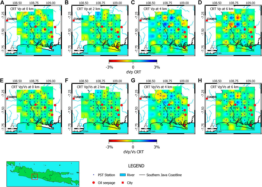
FIGURE 4. Horizontal view of recovery from ±10% initial checkerboard resolution tests for Vp and Vp/Vs ratio. Figure (A–D) are recovery of the Vp checkerboard test at 0–6 km depth, while figure (E–H) show recovery of the Vp/Vs checkerboard test at 0–6 km depth. Blue and red colors indicate positive and negative anomalies, respectively. Random noise with a 0.1 s standard deviation was added to the synthetic travel time.
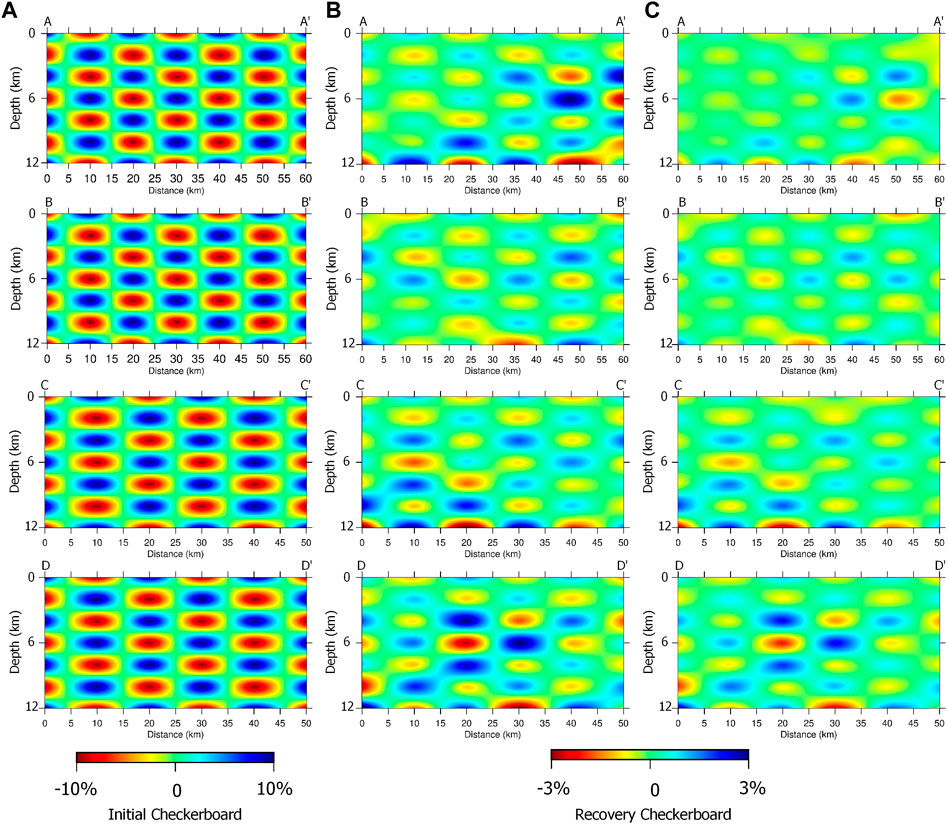
FIGURE 5. (A) The vertical cross section of a ±10% initial model checkerboard resolution test, and the recovery checkerboard resolution test of the Vp (B) and Vp/Vs ratio (C) for A–A′, B–B′, C–C′, and D–D′, respectively.
Interpretation of Results
Travel time tomography inversion results are presented in vertical and horizontal cross sections of the Vp structure, and in horizontal cross sections of Vs structure and Vp/Vs ratio, which will be covered in the following discussion. Horizontal cross sections will be presented in every 2 km, starting from 0 km (mean sea level), while vertical cross sections will be presented on the sections passing through the Jati-1 well and oil seepage on the surface. The cross sections of A–A′ and D–D′ passed through the Jati-1 exploration well and oil seepage on the surface, while the cross sections of B–B′ and C–C’ passed through oil seepage on the surface. Vertical cross sections that passed through oil seepage and the Jati-1 well were further analyzed for interpretation in several geological structures that have potential as hydrocarbon traps.
In this study, we also used the results of other geophysical studies such as the gravity anomaly map and 2-D seismic reflection sections (Tampubolon et al., 2014) to validate the vertical cross section of our seismic tomography results. The surface geology and the residual gravity anomaly map are used as validation for our horizontal cross sections. Using the PST method, we tried to investigate the geological structure in the form of anticline, which can be an ideal structural trap for the Banyumas Basin petroleum system; however, detailed explanations related to lithological interpretations will not be presented in this article.
Horizontal Sections of the Vp Structure
Figure 6 shows the result of using a previously available study in the study area; that is, the gravity anomaly and the regional Miocene structure for comparison with our horizontal cross section; while Figure 7 shows our Vp horizontal cross section results from 0 to 6 km depth; each of our horizontal cross sections is displayed in % perturbation relative to the initial 1-D Vp model. We characterize the presence of the Cipari anticline as a high-velocity anomaly which has a relative NW–SE orientation. We also observed a high-velocity anomaly presence as a volcanic rock in the Gabon Formation in the southwest of the study area based on a comparison of the regional geological map of the study area with a horizontal cross section at 0 km depth (Figure 7A). The existence of the Citanduy Subbasin and the Majenang Subbasin can also be imaged in the horizontal cross section Vp at a depth of 2 km (Figure 7B), which is comparable to the residual gravity anomaly. Furthermore, we can still delineate some similar geological features, which are shown in the horizontal Vp section at a depth of 2 km. It was seen that the velocity structure Vp has good compatibility with some geological features, such as the Cipari anticline pattern, which has a relative NW–SE orientation, and some lithological distribution patterns such as the outcrop of the Gabon Formation, which is characterized by a high-velocity anomaly in the southwest part of the study area.
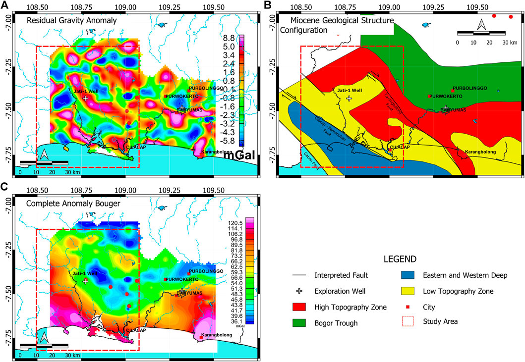
FIGURE 6. Previous studies available for the study area were used for comparison with our horizontal cross section results: (A) A residual gravity anomaly (modified from Hidayat et al., 2020), (B) the regional Miocene geological structure configuration of the southern part of Central Java (modified from Muchsin et al., 2002), and (C) the complete Bouger anomaly map (modified from Hidayat et al., 2020).
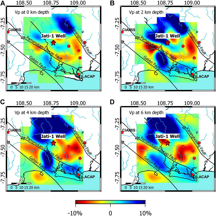
FIGURE 7. Horizontal cross section results of % velocity perturbation relative to the initial 1-D velocity model for: (A) 0 km depth, (B) 2 km depth, (C) 4 km depth, and (D) 6 km depth. Jati-1 well location is shown by a red star, while oil seepage discoveries are shown by red circles. The low-velocity anomaly, shown by red color, confirmed a low gravity anomaly (Figure 6A) and interpreted as possible subbasins around the study area. The Miocene geological structure of Figure 6B was overlaid over the Vp horizontal cross sections map.
Based on the study of Miocene-aged geological regional structure configurations in the study area (Muchsin et al., 2002), it was seen that there are three dextral strike-slip fault structures that extend in an NW–SE orientation, that is, the Gabon Fault, the Cilacap–Pamanukan Fault, and the Karangbolong Fault. Based on our horizontal cross section of the Vp, we can clearly identify Citanduy and Majenang Subbasin. We can also clearly identify the Gabon Fault and the Karangbolong Fault located in the southwestern and northeastern part of our study area at 0 and 2 km depths (Figures 7A,B); although the velocity contrast indicating the Pamanukan–Cilacap strike-slip fault trend was not clearly imaged. We assume that at depths of 2 km or shallower, some segments of the Pamanukan–Cilacap strike-slip fault are covered by sediment deposited after this structure was formed. Our assumption is also supported by the results of the Jati-1 well interpretation (Table 1), which shows that rock units in the Late Miocene Rambatan Formation were still deposited to depths of 2 km. At depths of 4 and 6 km, respectively, as shown in Figures 7C,D, the contrast of the Vp anomaly is interpreted as dextral regional strike-slip faults that is the Gabon Fault, the Pamanukan–Cilacap Fault, and the Karangbolong Fault as mentioned by the previous study as the Miocene geological structure of the southern part of Central Java (Muchsin et al., 2002). A low-velocity anomaly (Figures 7C,D) indicates a thick sedimentary rock deposit generated by the presence of an echelon structure as obtained based on the anomaly contrast of the Vp/Vs ratio; we assume that these regions may be the depocenter of the Banyumas Basin.

TABLE 1. Facies analysis based on Jati-1 well log data (Tampubolon et al., 2014).
Horizontal Sections of Vs and Vp/Vs Ratio
Figure 8 shows the result of Vp/Vs ratio and the Vs structure. Compared to horizontal Vp structures, our results showed high Vp, Vs, and low Vp/Vs values were imaged at depths of 0–4 km around the Jati-1 exploration well region. We consider this region as the result of the Pliocene–Pleistocene tectonic compression (Pulunggono and Martodjojo, 1994) which formed an anticline structure and separated the Majenang and the Citanduy Subbasin. However, low Vp, Vs, and high Vp/Vs values, which were imaged at depths of 6 km around this Jati-1 exploration well region, might be an accumulation of Late Cretaceous–Eocene sediment.
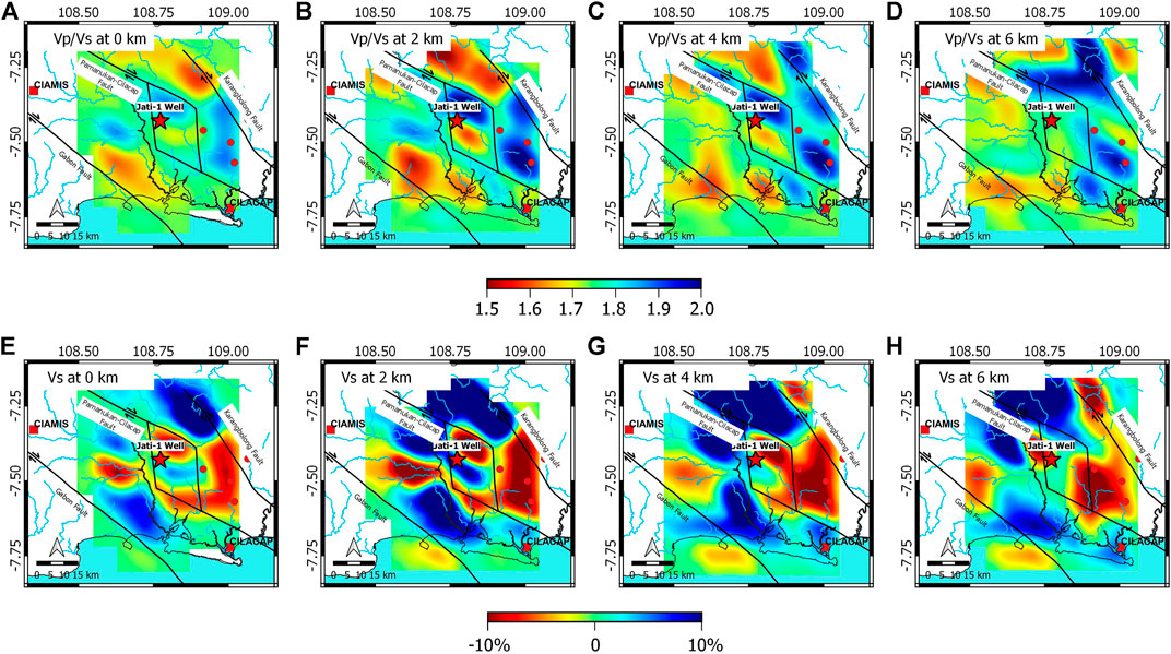
FIGURE 8. Horizontal sections Vp/Vs ratio and the Vs structure at (A) 0 km depth, (B) 2 km depth, (C) 4 km depth, and (D) 6 km depth, and perturbation of Vs anomaly at (E) 0 km depth, (F) 2 km depth, (G) 4 km depth, and (H) 6 km depth. Based on an anomaly contrast of Vp/Vs ratio at 2 and 4 km depth, we assume that Pamanukan–Cilacap strike-slip fault formed an echelon structure that controls the depocenter of the Banyumas Basin.
Based on the Vp/Vs ratio value, we obtained a NW–SE trending anomaly distribution pattern (Figure 8); we divided Vp/Vs value into two regions that is a high Vp/Vs value (>1.80) and a low Vp/Vs value (<1.7 0) which indicates the change of lithology according to the regional geology map. The change of lithology indicates that the Pamanukan–Cilacap strike-slip fault structure forms an echelon structure, which probably controls the formation of depocenter from the Banyumas Basin. This explains the presence of a low gravity anomaly around the Jati-1 exploration well. We assume this may be one of the possible reasons why, up to a depth of 4400 m, the Jati-1 exploration well has not found any rock formations older than the Middle Miocene–aged Pemali Formation (Table 1). Like the Vp structure, the Vs structure shows a similar anomaly distribution pattern. Figure 8E,F show comparable results with the residual gravity anomaly, while Figure 8G,H show comparable results with the complete Bouger anomaly. We interpret that the low-velocity anomaly around the Jati-1 exploration well region in Figure 8G,H shows the depocenter zone of the Banyumas Basin. This is confirmed by the presence of thick sedimentary deposits characterized by a low-velocity anomaly around the Pamanukan–Cilacap strike-slip fault in the vertical sections of the Vp structure. Some discoveries of oil seepage on the surface were also found around this structure with a similar NW–SE orientation, as seen in Figure 9.
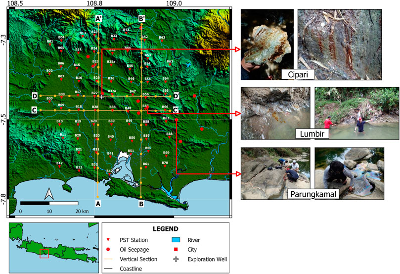
FIGURE 9. Overlay of oil seepage data distribution and Jati-1 exploration well to the vertical section of the Vp, Vs, and Vp/Vs ratio based on travel time tomography inversion results around the PST network (modified from Junursyah et al., 2019).
Vertical Sections of Vs and Vp/Vs Ratio
We attempted to interpret four sections which are passing through the Jati-1 well and oil seepage on the surface (see map on Figure 9). In Figure 10, we presented vertical sections of Vp, Vs, and Vp/Vs ratio. Based on A–A′ and D–D′ vertical sections of Vp and the Vs structure, the Jati-1 well is directly above the anticline structure with a target depth of 4400 m and characterized by high value of both Vp and Vs, while Vp/Vs ratio in the A–A′ and D–D′ sections indicate a low anomaly region (<1.70) in the target depth of Jati-1 well. Vp/Vs ratio is sensitive to identify fluid type (Hamada, 2004; Tselentis et al., 2007), a low Vp/Vs ratio value indicates the presence of gas-bearing or high fluid compressibility, while a high Vp/Vs ratio value indicates a liquid-bearing or low fluid compressibility (Tselentis et al., 2007). We assume that the existence of this high Vp, Vs, and the low Vp/Vs value in this region (shown by the black dashed curve circle), might be a possible reason why the Jati-1 well has not found any indication of liquid-bearing at a depth of 4400 m.
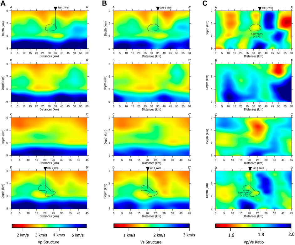
FIGURE 10. Vertical sections of Vp (A), Vs (B), and Vp/Vs ratio (C). Line A–A′ and D–D′ intersected Jati-1 well (shown by black-colored inverted triangle) with a target depth of 4, 400 m. Based on vertical sections of Vs, the Jati-1 well is directly above the anticline structure as shown by Vp and Vs vertical sections. In the target depth of Jati-1 well, Vp/Vs ratio shows a low anomaly region (<1.7).
Vertical Sections of Vp
In Figure 11, both the A–A′ and D–D′ cross sections pass through the Jati-1 exploration well and succeed in determining the geological contact of the Halang and Rambatan formations, according to the interpretation of the Jati-1 exploration well (Table 1) which states that the top of the Rambatan Formation is at a depth of 1, 250 m and which is also shown in the velocity contrast, characterized by blue line of the Vp structure cross sections. The Halang Formation has a significant role in the Banyumas Basin petroleum system. Mudstone in the Halang Formation is expected to be potential caprocks in the petroleum system for the Banyumas Basin. Regional structures similar to fold structure patterns (anticline–syncline) can also be imaged well, based on cross sections of the Vp structure; these show comparable results with the residual gravity anomaly response obtained from the previous study (Hidayat et al., 2020). We extracted the value of the residual gravity anomaly on sections A-A′, B–B′, C–C′, and D–D′ and made comparisons with the results of the tomographic inversions (Figure 11). B–B′ and C–C′, respectively, are vertical cross sections that have a west–east and south–north orientation. Both of these vertical cross sections pass through oil seepage on the surface. We characterize the geological contact of the Halang and Rambatan formations based on the velocity contrast from these vertical sections. These sections show that the top of the Rambatan Formation is in a shallower depth than those found in the A–A′ and D–D′ vertical sections, due to the higher gravity anomaly response in the B–B′ and C–C’ vertical cross sections. Anticline–syncline structure patterns can also be well imaged on these vertical cross sections, considering the high–low residual gravity anomaly in the respective sections (Figure 11).
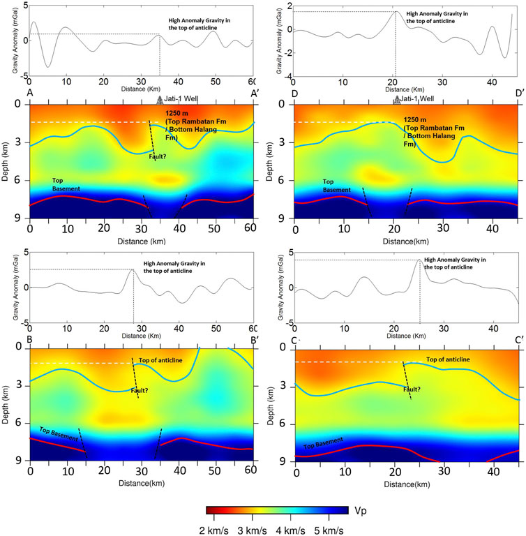
FIGURE 11. The residual gravity anomaly response (Hidayat et al., 2020) and the vertical cross sections of Vp which pass through the Jati-1 well in sections A–A′, D–D′, B–B′, and C–C′. Blue line indicates geological contact between the Halang Formation and the Rambatan Formation, which is also confirmed by interpretation of Jati-1 well (Tampubolon et al., 2014). We also interpreted top of basement based on the high-velocity anomaly (>5 km/s) which is shown by red line.
The anticline structure was obtained at the intersection of the A–A′ and D–D′ cross sections, as well as the location of the Jati-1 well drilling. A similar structure was also obtained at the intersection of D–D′ and B–B′ cross sections.
The top of the Pemali Formation is definitely unknown based on the Jati-1 well because there is no data for depths of 2,451–4328 m. Based on an interpretation of the A–A′ and D–D′ vertical cross sections, we try to investigate the top of the Rambatan Formation in all of the other Vp sections. Based on velocity contrast, and constraint from the gravity anomaly response, we delineate similar subsurface geological features, such as anticline and syncline structure patterns, on the B–B′ and C–C’ sections (Figure 11). The anticline structure is expected to be a good trapping mechanism for the Banyumas Basin.
To validate our results, we attempted to make a comparison between 2-D seismic reflection cross-sectional interpretations (Tampubolon et al., 2014) using the travel time tomography inversion (see map in Figure 12). Based on the results of these comparisons, we obtained a comparable pattern of subsurface anticline–syncline patterns in both the 2-D seismic reflection cross section and the travel time tomography inversion section. The top of the anticline was found in the Jati-1 exploration well (Figure 13B) which is the most common structure for a hydrocarbon trap. The subsurface anticline pattern has the same pattern as the anticline trend that is exposed on the surface, forming an elongated pattern in a NW–SE direction.
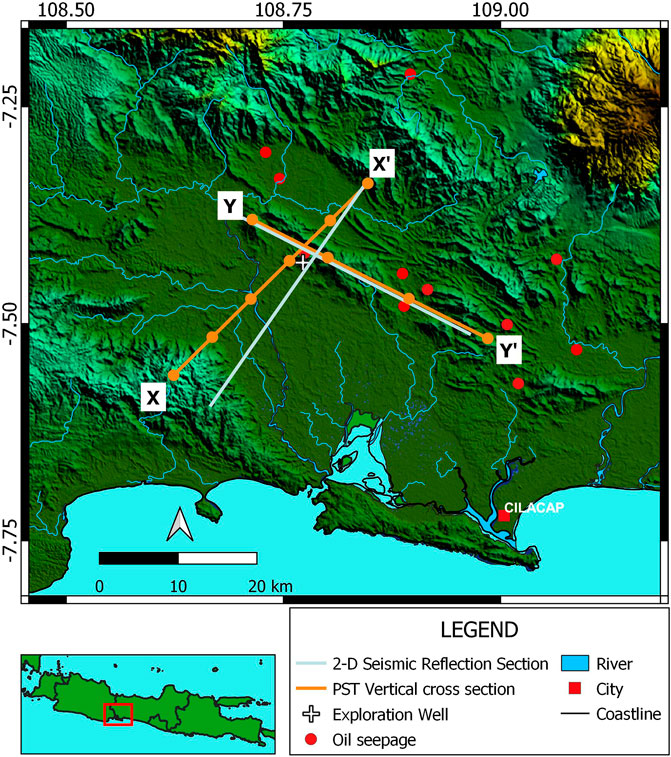
FIGURE 12. Directions along which the vertical tomographic sections have been compared to 2-D seismic reflection sections (Tampubolon et al., 2014).
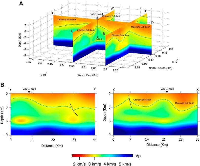
FIGURE 13. (A) The intersection of the D–D′, A–A′, and B–B′ that pass through Jati-1 exploration well. Velocity contrast shows geological contact of the Halang Formation and the Rambatan Formation. Top of the anticline structure separate Citanduy Subbasin in the southern part and Majenang Subbasin in the northern part and (B) tomography inversion results of the X–X′ and Y–Y′ which depicted some geological structures (i.e., faults and anticline) as 2-D seismic reflection sections (Tampubolon et al., 2014).
In the southwest of cross-section X–X′, we found an outcrop of the volcanic Gabon Formation which was deposited during the Oligocene–Miocene period and is also the oldest rock outcrop in the study area. The high Vp and Vs anomaly at depth of 0 km (mean sea level) in the southwestern part of the X–X′ cross section is interpreted as an indication of the existence of these volcanic deposits. The Cipari anticline trend separates two low anomalies; the Citanduy Subbasin, southwest of the anticline, and the Majenang Subasin, northeast of the anticline. The contrast of the velocity anomaly was found at both the X–X′ and the Y–Y’ cross sections at a depth of 1, 250 m, which is interpreted as the geological contact between the Halang and the Rambatan formations.
Conclusion
Our PST network consisted of 70 stations with three components that were installed in the Banyumas Basin, south of Central Java, Indonesia, and covered 45 km × 60 km of the study area to perform a PST investigation of subvolcanic structures related to the petroleum system. We managed to determine 354 events with 9370 P-phases and 9368 S-phases as our input for the tomographic inversion. The application of a local 1-D velocity model, using Jati-1 well checkshot data, succeeded in specifying the presence of a more detailed geological structure in a shallow depth. We also assessed the resolution and reliability of our results using the checkerboard resolution test, the diagonal resolution element, and the derivative weight sum. According to these three methods, the area within our network is still well resolved and reliable for interpretation. Application of the travel time tomography method by installing a dense seismograph station and a local 1-D velocity model using checkshot data can provide a satisfactory correlation with other geophysical methods and geologic structures related to the delineation of trapping mechanisms for the petroleum system in the Banyumas Basin.
Based on the results of our tomographic inversion, we obtained geometries similar to geological structures in the form of fold structures with the top of the anticline found at the Jati-1 exploration well. The top of the anticline is interpreted as a subsurface image of the Cipari anticline trend confirmed by the regional geology map, 2-D seismic reflection methods, and a residual gravity anomaly.
The velocity contrast of the tomographic inversion results is interpreted as the geological contact between the Halang and Rambatan formations; this interpretation correlates with the results of the Jati-1 well interpretation. Mudstone from the Halang Formation can be a caprock for the Banyumas Basin petroleum system, with the anticline structure as a trap mechanism.
Our tomographic inversion results are highly comparable with those of previous studies, such as gravity, 2-D seismic reflection, and the geological structure. Based on the comparison of the Vp horizontal cross section with the regional geological map in the study area, the high-velocity anomaly shows a comparable pattern with the distribution of volcanic rocks from the Gabon Formation in the southwest part of the study area. Meanwhile, based on the comparison between the horizontal cross section and the residual gravity anomaly, the high-velocity anomaly with a NW–SE orientation is interpreted as a subsurface image of the Cipari anticline trend that separates the Citanduy Subbasin and the Majenang Subbasin at a depth of 2 km. Based on horizontal cross sections of the Vp/Vs ratio at depths of 2 and 4 km, we suggested that the Pamanukan–Cilacap strike-slip Fault likely formed an echelon structure that controlled depocenter in our study area. We assume this may be the possible reason why, up to a depth of 4, 400 m, the Jati-1 well has not found any rock formations older than the Middle Miocene–aged Pemali Formation, and it also explains why there are low gravity anomaly regions around Jati-1 well. Based on our Vp and Vs structure results at depths of 0 and 2 km the Pamanukan–Cilacap dextral strike-slip faults structure cannot be clearly delineated; this confirms that depths of 0–2 km are still dominated by sediment deposited after this fault structure was formed (Late Miocene–Quaternary). This interpretation is validated by Jati-1 exploration well data, which show the presence of Late Miocene sedimentary rocks from the Rambatan Formation up to a depth of 2 km.
The top basement of the Banyumas Basin was obtained from the results of vertical cross sections showing high P-wave velocity anomalies, which are greater than 5,000 m/s; characterized by red line in the vertical cross sections of Vp. From the resulting model of our vertical cross section, we estimate that the depth of the Banyumas Basin top basement has an average depth of around 8 km. Deposition of thick sedimentary rocks provides opportunities for the presence of petroleum systems in the Banyumas Basin.
This study has succeeded in determining several zones of geological features which are potential structural traps of the petroleum system in the Banyumas Basin, although the type of stratigraphic traps in the form of reef and onlap cannot be resolved.
Data Availability Statement
The seismic velocity tomograms presented in this study are available in the article/Supplementary Material; further inquiries can be referred to the corresponding author.
Author Contributions
HH, MM, JS, EL, AP, and AS conceived the survey and seismic study on the Banyumas Basin. HH, AN, AP, MM, DS, SW, SR, and ZZ contributed to the writing of the manuscript. All authors contributed to the preparation of the manuscript. All authors have read and approved the final manuscript.
Funding
This study was supported by the Ministry of Energy and Mineral Resources, Indonesia, for its scholarship, ITB Research 2019-2020 Program, the Master's Thesis Research Program BP-PTNBH Kemristek/BRIN 2020, and World Class Research 2021-2022 awarded to A.D.N. The study was also partially supported by the Center for Earthquake Science and Technology, and the Research Center for Disaster Mitigation, Institut Teknologi Bandung (CEST, PPMB, ITB).
Conflict of Interest
The authors declare that the research was conducted in the absence of any commercial or financial relationships that could be construed as a potential conflict of interest.
Acknowledgments
This study was a collaboration between Institut Teknologi Bandung (ITB) and the Geological Agency of Indonesia c.q the Center for Geological Survey (CGS). We gratefully acknowledge CGS for the waveform data used in this study. Generic Mapping Tools (Wessel and Smith 1998) were used to produce the figures.
Supplementary Material
The Supplementary Material for this article can be found online at: https://www.frontiersin.org/articles/10.3389/feart.2021.639271/full#supplementary-material
References
Armandita, C., Mukti, M. M. R., and Satyana, A. H. (2009). Intra-Arc Trans-tension Duplex of Majalengka to Banyumas Area: Prolific Petroleum Seeps and Opportunities in West-Central Java Border. Proc. Indon Petrol. Assoc., 33rd Ann. Conv, IPA09-G-173. doi:10.29118/ipa.2066.09.g.173
Asikin, S., Handoyo, A., Hendrobusono, S., and Gafoer, S. (1992). Geology of the Kebumen Quadrangle, Java, Scale 1:100.000. Bandung-Indonesia: Geological Research and Development Centre.
Budhitrisna, T. (1986). Geology of Tasikmalaya, Java, Scale 1:100.000. Bandung-Indonesia: Geological Research and Development Centre.
Djuri, M., Samodra, H., Amin, T. C., and Gafoer, dan. S. (1996). Geology of Purwokerto and Tegal. 2nd edition. Bandung-Indonesia: Geological Research and Development Centre.
Durham, L. S. (2003). Passive Seismic. Listen: Is it the Next Big Thing? AAPG Explorer. 24 (4), 127–131.
Eberhart-Phillips, D. (1986). Three-dimensional Velocity Structure in Northern California Coast Ranges from Inversion of Local Earthquake Arrival Times. Bull. Seismol. Soc. Am. 76 (4), 1025–1052.
Evans, J. R., Eberhart-Phillips, D., and Thurber, C. H. (1994). User's Manual for SIMULPS12 for Imaging Vp and Vp/vs; a Derivative of the “Thurber” Tomographic Inversion SIMUL3 for Local Earthquakes and Explosions. Open-File Rep. 94-431, 101. doi:10.3133/ofr94431
Geology Agency (2009). Peta Cekungan Sedimen Indonesia Berdasarkan Data Geologi Dan Geofisika, Skala 1: 5000.000 [Indonesia Sedimentary Basin Map Based on Geological and Geophysical Data, Scale 1: 5000.000. Bandung-Indonesia: Center for Geological Survey, Geological Agency.
Hamada, G. M. (2004). Reservoir Fluids Identification Using Vp/Vs Ratio? Oil Gas Sci. Technology - Rev. IFP. 59, 649–654. doi:10.2516/ogst:2004046
Handyarso, A., and Hidayat, (2019). Investigasi Cekungan Banyumas Menggunakan Metode Magnetotelurik (MT) [Investigation of Banyumas Basin Using Magnetotelluric Method (MT)]. Publikasi Khusus Eksplorasi Hidrokarbon di Sistem Vulkanik. 67–79.
Hidayat, H., Subagio, S., and Praromadani, Z. S. A. (2020). Interpretasi Struktur Geologi Bawah Permukaan Berdasarkan Updating Data Gaya Berat Cekungan Banyumas, Jawa Tengah. JGSM.Geologi. 21 (3), 111–118. doi:10.33332/jgsm.geologi.v21i3.524
Indonesia Geology Agency (2009). Peta Cekungan Sedimen Indonesia Berdasarkan Data Geologi Dan Geofisika, Skala 1: 5000.000 [Indonesia Sedimentary Basin Map Based on Geological and Geophysical Data, Scale 1 : 5000.000. Bandung-Indonesia: Center for Geological Survey, Geological Agency.
Junursyah, G. M. L., Suteja, A., and Setyanta, B. (2019). Survei Geomagnet untuk Mendelineasi Cekungan Sedimen yang Tertutupi Batuan Vulkanik di Daerah Banyumas [Geomagnetic survey to delineate Sedimentary Basin covered by Volcanic Rocks in Banyumas Area]. Publikasi Khusus Eksplorasi Hidrokarbon di Sistem Vulkanik, 51–64.
Kapotas, S., Tselentis, G. A., and Martakis, N. (2003). Case Study in NW Greece of Passive Seismic Tomography: A New Tool for Hydrocarbon Exploration. first break. 21 (2), 37–42. doi:10.3997/1365-2397.2003021
Kastowo, (1975). Geology of Majenang, Scale 1:100.000, Direktorat Geologi Indonesia. Bandung, Indonesia: Geological Research and Development Centre.
Koulakov, I., Bohm, M., Asch, G., Lühr, B. G., Manzanares, A., Brotopuspito, K. S., et al. (2007). P and S Velocity Structure of the Crust and the Upper Mantle beneath central Java from Local Tomography Inversion. J. Geophys. Res. Solid Earth 112, B08310. doi:10.1029/2006jb004712
Lomax, A., and Michelini, A. (2009). Mwpd: a Duration-Amplitude Procedure for Rapid Determination of Earthquake Magnitude and Tsunamigenic Potential fromPwaveforms. Geophys. J. Int. 176, 200–214. doi:10.1111/j.1365-246X.2008.0397410.1111/j.1365-246x.2008.03974.x
Lomax, A. (2008). The NonLinLoc Software Guide. Mouans-SartouxFrance: ALomax Scientific. Available at:
Lomax, A., Virieux, J., Volant, P., and Berge-Thierry, C. (2000). “Probabilistic Earthquake Location in 3D and Layered Models,” in Advances in Seismic Event Location. Modern Approaches in Geophysics. Editors C.H. Thurber, and N. Rabinowitz (Dordrecht: Springer Netherlands), 101–134. doi:10.1007/978-94-015-9536-0_5
Lunt, P., Burgon, G., and Baky, A. (2009). The Pemali Formation of Central Java and Equivalents: Indicators of Sedimentation on an Active Plate Margin. J. Asian Earth Sci. 34 (1), 100–113. doi:10.1016/j.jseaes.2008.03.006
Martakis, N., Kapotas, S., and Tselentis, G.-A. (2006). Integrated Passive Seismic Acquisition and Methodology. Case Studies. Geophys. Prospect. 54 (6), 829–847. doi:10.1111/j.1365-2478.2006.00584.x
Martakis, N., Tselentis, A., Kapotas, S., and Karageorgi, E. (2003). “Passive Seismic Tomography a Complementary Geophysical Method–Successful Case Study,” in 65th EAGE Conference & Exhibitioncp-6. Stavanger: (European Association of Geoscientists & Engineers). doi:10.3997/2214-4609-pdb.6.p065
Maxwell, S. C., and Urbancic, T. I. (2001). The Role of Passive Microseismic Monitoring in the Instrumented Oil Field. The Leading Edge. 20 (6), 636–639. doi:10.1190/1.1439012
Muchsin, N., Ryacudu, R., Kunto, T. W., Budiyani, S., Yulihanto, B., Wiyanto, B., et al. (2002). Miocene Hydrocarbon System of the Southern Central Java Region. Surabaya: Indonesian Association of Geologists, 31st Annual Convention, 58–67.
Pulunggono, A., and dan Martodjojo, S. (1994). Perubahan tektonik Paleogen – Neogen merupakan peristiwa terpenting di Jawa [Paleogen – Neogen tectonic change is the most important event in Java]. Proccedings Geologi dan Geotektonik Pulau Jawa, 37–50.
Purwasatriya, E. B., Surjono, S. S., and Amijaya, D. H. (2019). Sejarah Geologi Pembentukan Cekungan Banyumas Serta Implikasinya Terhadap Sistem Minyak Dan Gas Bumi. Dinarek. 15, 25. doi:10.20884/1.dr.2019.15.1.242
Rutledge, J. T., and Phillips, W. S. (2003). Hydraulic Stimulation of Natural Fractures as Revealed by Induced Microearthquakes, Carthage Cotton Valley Gas Field, East Texas. Geophysics. 68 (2), 441–452. doi:10.1190/1.1567214
Rutledge, J. T., Phillips, W. S., and Schuessler, B. K. (1998). Reservoir Characterization Using Oil-Production-Induced Microseismicity, Clinton County, Kentucky. Tectonophysics. 289 (1-3), 129–152. doi:10.1016/s0040-1951(97)00312-0
Satyana, A. H. (2015). Subvolcanic Hydrocarbon Prospectivity of Java: Opportunities and Challenges. Proc. Indonesian petrol. Assoc., 39th Ann. Conv. IPA15-G-105, doi:10.29118/ipa.0.15.g.105
Setiawan, R. (2019). Sistem Hidrokarbon Pada Tatanan Vulkanik: Konsep Dan Studi Kasus [The Hydrocarbon System Related to Volcanism: Concepts and Case Studies]. Publikasi Khusus Eksplorasi Hidrokarbon di Sistem Vulkanik, 9–21.
Simandjuntak, T. O., and Surono, S. (1992). Geology of Pangandaran Scale 1:100000, 1308–2. Bandung-Indonesia: Geological Research and Development Centre.
Supriatna, S., Sarmili, L., Sudana, D., and Koswara, A. (1992). Geologic Map of Karangnunggal Quadrangle. Bandung-Indonesia: Geological Research and Development Centre.
Tampubolon, R. A., Tampubolon, A. S. O., Baskoro, A. S., and Lagon, R. (2014). Evolusi Stratigrafi, Analisis Fasies, dan Geokimia Dari Sedimen Mio-Pliosen di Cekungan Banyumas [Stratigraphic Evolution, Facies Analysis and Geochemistry of Mio-Pliosen Sedimentary deposit in Banyumas Basin]. Jakarta: The 43st IAGI Annual Convention and Exhibition.
Tarantola, A., and Valette, B. (1982). Inverse Problems= Quest for Information. J. Geophys. IF 32.18 50 (1), 159–170.
Thurber, C. H. (1993). Local earthquake tomography: velocities and Vp/Vs-theory, in Seismic Tomography: Theory and practice. Editors H. M. Iyer and K. Hirahara (Chapman and Hall), 563–583.
Toomey, D. R., and Foulger, G. R. (1989). Tomographic Inversion of Local Earthquake Data from the Hengill-Grensdalur Central Volcano Complex, Iceland. J. Geophys. Res. 94 (B12), 17497–17510. doi:10.1029/JB094iB12p17497
Tselentis, G.-A., Martakis, N., Paraskevopoulos, P., and Lois, A. (2011). High-resolution Passive Seismic Tomography for 3D Velocity, Poisson's Ratio ν, and P-Wave Quality QP in the Delvina Hydrocarbon Field, Southern Albania. Geophysics. 76 (3), B89–B112. doi:10.1190/1.3560016
Tselentis, G.-A., Serpetsidaki, A., Martakis, N., Sokos, E., Paraskevopoulos, P., and Kapotas, S. (2007). Local High-Resolution Passive Seismic Tomography and Kohonen Neural Networks - Application at the Rio-Antirio Strait, central Greece. Geophysics. 72 (4), B93–B106. doi:10.1190/1.2729473
Um, J., and Thurber, C. H. (1987). A Fast Forward Algorithm for Two-point Seismic ray Tracing. Bull. Seismol. Soc. Am. 77 (3), 972–986.
Keywords: Banyumas Basin, passive seismic tomography, VP, volcanic sediment, hydrocarbon structure
Citation: Hidayat H, Nugraha AD, Priyono A, Marjiyono M, Setiawan JH, Sahara DP, Winardhi S, Zulfakriza Z, Rosalia S, Lelono EB, Permana AK and Setiawan A (2021) Travel Time Tomography to Delineate 3-D Regional Seismic Velocity Structure in the Banyumas Basin, Central Java, Indonesia, Using Dense Borehole Seismographic Stations. Front. Earth Sci. 9:639271. doi: 10.3389/feart.2021.639271
Received: 08 December 2020; Accepted: 10 May 2021;
Published: 18 June 2021.
Edited by:
Basilios Tsikouras, Universiti Brunei Darussalam, BruneiReviewed by:
Michael Weber, Helmholtz Centre Potsdam, GermanyYojiro Yamamoto, Japan Agency for Marine-Earth Science and Technology, Japan
Copyright © 2021 Hidayat, Nugraha, Priyono, Marjiyono, Setiawan, Sahara, Winardhi, Zulfakriza, Rosalia, Lelono, Permana and Setiawan. This is an open-access article distributed under the terms of the Creative Commons Attribution License (CC BY). The use, distribution or reproduction in other forums is permitted, provided the original author(s) and the copyright owner(s) are credited and that the original publication in this journal is cited, in accordance with accepted academic practice. No use, distribution or reproduction is permitted which does not comply with these terms.
*Correspondence: Andri Dian Nugraha, bnVncmFoYUBnZi5pdGIuYWMuaWQ=
 Hidayat Hidayat
 Andri Dian Nugraha
 Awali Priyono3
 David P. Sahara
 Zulfakriza Zulfakriza
 Shindy Rosalia