 Prospero De Martino1,2
 Sergio Guardato1
 Gian Paolo Donnarumma1
 Mario Dolce1
 Tiziana Trombetti3Francesco Chierici4
 Giovanni Macedonio1
 Laura Beranzoli5
 Giovanni Iannaccone1*
- 1Istituto Nazionale di Geofisica e Vulcanologia, Sezione di Napoli Osservatorio Vesuviano, Napoli, Italy
- 2Istituto per il Rilevamento Elettromagnetico dell’Ambiente, Consiglio Nazionale delle Ricerche (IREA-CNR), Napoli, Italy
- 3Istituto di Scienze Marine, Consiglio Nazionale delle Ricerche (ISMAR-CNR), Bologna, Italy
- 4Istituto Nazionale di Astrofisica - Istituto di Radioastronomia, Bologna, Italy
- 5Istituto Nazionale di Geofisica e Vulcanologia, Sezione Roma2, Roma, Italy
We present 4 years of continuous seafloor deformation measurements carried out in the Campi Flegrei caldera (Southern Italy), one of the most hazardous and populated volcanic areas in the world. The seafloor sector of the caldera has been monitored since early 2016 by the MEDUSA marine research infrastructure, consisting of four instrumented buoys installed where sea depth is less than 100 m. Each MEDUSA buoy is equipped with a cabled, seafloor module with geophysical and oceanographic sensors and a subaerial GPS station providing seafloor deformation and other environmental measures. Since April 2016, the GPS vertical displacements at the four buoys show a continuous uplift of the seafloor with cumulative measured uplift ranging between 8 and 20 cm. Despite the data being affected by environmental noise associated with sea and meteorological conditions, the horizontal GPS displacements on the buoys show a trend coherent with a radial deformation pattern. We use jointly the GPS horizontal and vertical velocities of seafloor and on-land deformations for modeling the volcanic source, finding that a spherical source fits best the GPS data. The geodetic data produced by MEDUSA has now been integrated with the data flow of other monitoring networks deployed on land at Campi Flegrei.
Introduction
Seafloor geodesy is now an established branch of geodesy for precise underwater measurements of position and displacements and is used for monitoring submerged volcanic areas, tectonic deformation and subsidence related to offshore oil extraction. The main analysis methodologies used are based on acoustic waves propagation and pressure measurements.
Acoustic methods use travel time measurements of acoustic wave packets between two reference locations together with estimation of the seawater sound speed. Two main acoustic techniques have been developed: 1) a GPS-Acoustic combination technique (GPS/A) where a kinematic GPS on a platform at the sea surface is combined with acoustic wave ranging to determine the position of a network of transponder on the seafloor (Bürgman and Chadwell, 2014) This technique has been used extensively to investigate crustal deformation at oceanic spreading centers and subduction thrust faults; usually the measurements are performed in campaign-style with research vessels or light inexpensive floating GPS stations using a glider. 2) horizontal distance measurements between two or more transponders; this is applied to relative deformation measurements across geological features (Petersen et al., 2019).
The main limitation of the acoustic techniques arises from the variation over time of properties of the marine environment, with the consequent difficulty estimating the path length starting from the measurement of the propagation time.
Another common technique in marine geodesy that is suitable for monitoring vertical ground displacement is based on the variation of hydrostatic pressure at the sea bottom measured by a bottom pressure recorder (BPR). However, BPR measurement suffers from greater uncertainties than GPS. To achieve the centimeter accuracy in the Up component need for seafloor deformation monitoring, BPR time series must be integrated with other complementary measurements such as sea level observations at local tide gauges, atmospheric pressure measurements and measures related to seawater column density (i.e. salinity and temperature). Moreover, an erratic instrumental drift of BPRs must be taken into account (Chierici et al., 2016).
Geodetic measurements on the seafloor are more frequently performed at large depths, typically greater than 1,000 m, than in shallow water. This is because the large variability over time of the sound speed strongly degrades the quality of acoustic measures. The sound speed in sea water depends on the temperature and salinity, which, in turn, are strongly affected by solar radiation, by seasonal cycles, and by water mixing due to sea currents. This variability is particularly pronounced in the shallow layers of coastal areas, where additionally, the presence of rivers or waste waters introduce further variability in water properties. Similarly, the variability of temperature and salinity over the time produces sea density changes detected as pressure variation by the BPR sensors. Consequently, long term pressure measurements are contaminated by a high level of noise that can be removed only with precise knowledge of the sea water density profile over the time (Chierici et al., 2016).
A new methodology for seafloor geodesy measurements suitable for shallow water environments, less than 100 m depth, was recently introduced in Southern Italy. A buoy, named CUMAS (Cabled Underwater Multidisciplinary Acquisition System, Iannaccone et al., 2009; Iannaccone et al., 2010) was deployed in November 2006, at a sea depth of 97 m in the Gulf of Pozzuoli, the marine sector of the Campi Flegrei volcanic area, for an experiment of acoustic data transmission. In 2012, the CUMAS buoy was equipped with a GPS station.
The CUMAS buoy consists of an underwater floating body attached to a concrete anchor ballast on the seafloor. The ballast holds the floating body fixed a few meters below the sea level so it is not affected by sea level variations (Iannaccone et al., 2009). A pole supporting a subaerial, top turret is inserted into the body, allowing a GPS station installed on top of the pole to be rigidly coupled to the seafloor and allowing direct recording of seafloor displacement. De Martino et al. (2014a) showed that the CUMAS GPS station measured a seafloor uplift of about 3–4 cm over 17 months from January 2012 to May 2013, demonstrating the validity of this conceptually simple system for geodetic measurements in shallow waters. Given the success of the CUMAS experiment, three new buoys with GPS stations were deployed in early 2016 in the Gulf of Pozzuoli, forming the MEDUSA (Multiparametric Elastic-beacon Devices and Underwater Sensor Acquisition system) infrastructure.
Here we present the data acquired in continuous mode by the GPS stations of the MEDUSA infrastructure for 4 years after April 2016 and examine their contribution to the interpretation of the ground deformation pattern of the Campi Flegrei caldera.
Materials and Methods
MEDUSA Infrastructure Outline
The MEDUSA infrastructure consists of four spar buoys installed in the Gulf of Pozzuoli at 1.1 to 2.4 km from the coast and water depths less than 100 m (colored dots in Figure 1).
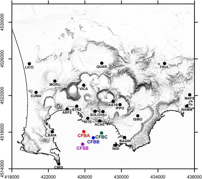
FIGURE 1. Map of cGPS stations operating in the Campi Flegrei area. Black dots indicate the on land stations of the NeVoCGPS network; colored dots represent the cGPS stations installed on MEDUSA infrastructure.
Two buoys (CFBA and CFBC), deployed where seafloor depth is about 40 m, have a long pole connecting the float and subaerial part to the ballast on the sea bottom. For these two buoys the distance between the GPS antenna and the ballast is about 47.5 m. The other two buoys (CUMAS prototype and CFBB), operating where seafloor depth is about 96 and 76 m respectively, use a steel cable to fasten the pole to the ballast (Figure 2A). CFBB has a pole the same length as for CFBA and CFBC joined to a steel cable of 33 m length, while the CUMAS buoy has a pole of 26 m long and a steel cable of 83 m. The floats of CUMAS and CFBB provide a buoyancy force acting on the ballast and keeping the steel cable under tension. Functionally, each buoy behaves as a system rigidly anchored to the seabed so the top of the buoy where the GPS antenna is installed follows directly vertical movement of the seabed. Figure 2B, shows in a simplified view the length of the buoys compared to a reference monument and also the proportion of the pole length for each buoy type.
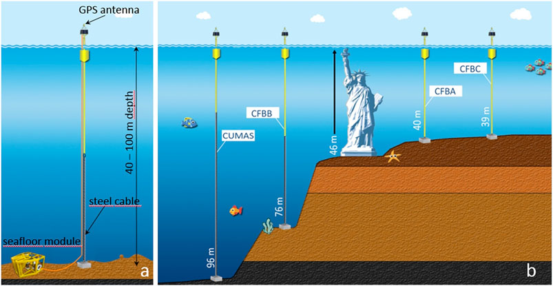
FIGURE 2. Layout of the buoys. (A) schema of a buoy; (B) comparison of the length of each buoy installation with the Statue of Liberty in New York, United States. The rigid pole is shown in yellow and the flexible steel cable in black.
Each buoy is connected by a power supply and data transmission cable to a seafloor module equipped with geophysical and oceanographic sensors placed a few meters from the buoy ballast (Figure 2A). Each module includes: a three-component broadband seismic sensor, two low-frequency omnidirectional hydrophones, a three-component MEMS accelerometer and an absolute pressure recorder. A titanium vessel contains acquisition systems, status and control sensors, and electronics. Power supply, data transmission and clock signals to the module equipment are provided through an armored, electro-mechanical cable, which also serves for module handling and installation/recovery. On the top of the buoy, a subaerial turret hosts the power supply system (solar panels and buffer batteries), and data transmission and control electronics. Real-time data transmission to a land acquisition center is provided by 5 GHz Wi-Fi. Each buoy is equipped with a Leica GR10 GPS receiver and AR20 antenna. GPS data are acquired with a sampling interval of 30 s and downloaded daily by the INGV-Monitoring Center in Naples for storage and processing. A digital compass measuring the attitude of the buoy is mounted on the turret. One buoy is also equipped with a meteorological station (temperature, humidity, atmospheric pressure, wind direction and speed).
MEDUSA has allowed extension into the Gulf of Pozzuoli of the Campi Flegrei geophysical monitoring system, which was exclusively land-based before 2016, improving the observation and assessment of seafloor deformation in the area and observation and location of earthquakes. MEDUSA is fully integrated in the Campi Flegrei surveillance system: all the data acquired are transmitted to a unique, land acquisition center where they are analyzed and stored together with the data provided by the other land monitoring networks.
cGPS Data Processing and Time Series Analysis
Continuous Global Positioning System (cGPS) data are available since April 2016 for the CFBA, CFBB and CFBC stations and since July 2016 for the CFSB station. The cGPS data has been processed in kinematic mode with the open source program package RTKLIB ver. 2.4.2 (http://www.rtklib.com) to obtain positions of the buoys every 30 s. The reference station for cGPS data processing is LICO (Figure 1), located at a distance of about 10 km from the caldera center (a full description of the kinematic cGPS processing is reported in De Martino et al., 2014a).
The kinematic time series of the MEDUSA cGPS stations showing the position changes every 30 s for the North, East and Vertical (Up) components (m) are shown in Figures 3A–6A.
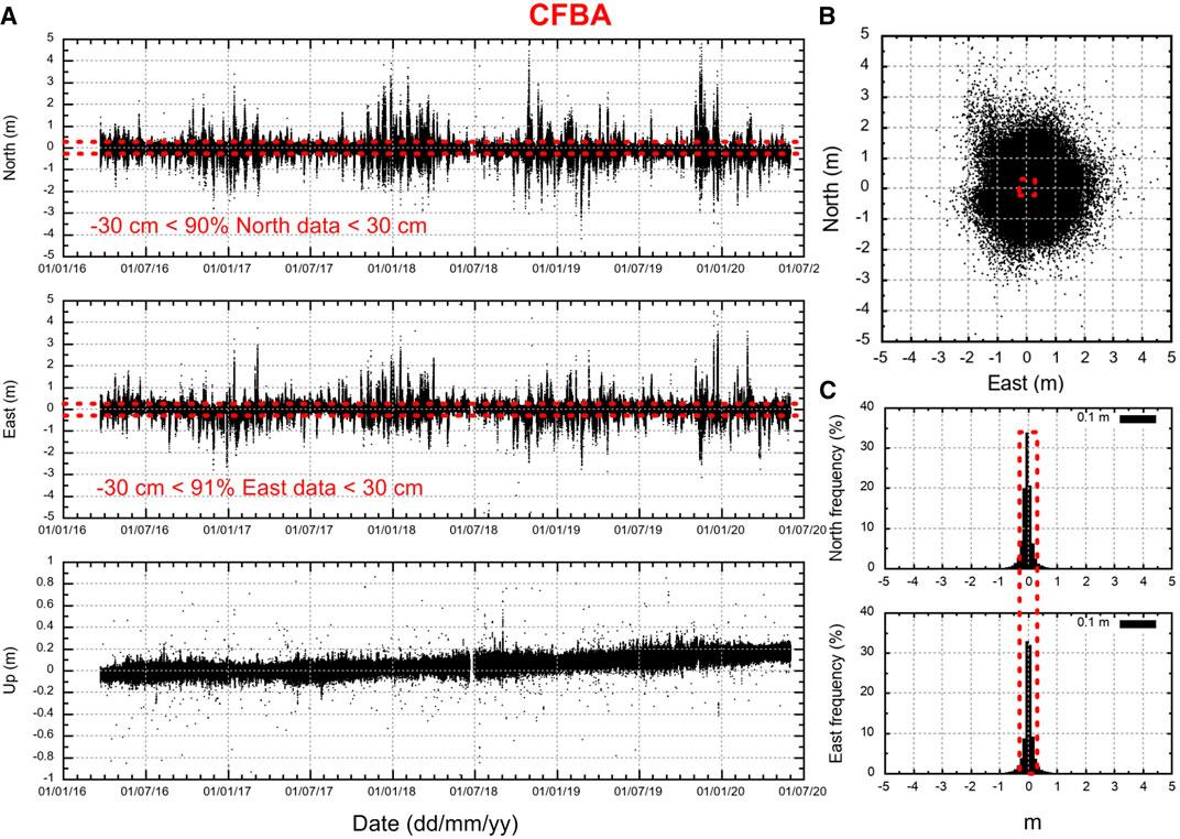
FIGURE 3. GPS kinematic time series (30 sec sampling) of the CFBA station. (A) North (top row), East (middle row) and Up (bottom row) components; (B) GPS kinematic positions shown in the horizontal plane; (C) Frequency histogram of the horizontal components. Over 90% of the horizontal positions of the buoy are within 30 cm of the origin, taken as the mean horizontal position in the considered period.
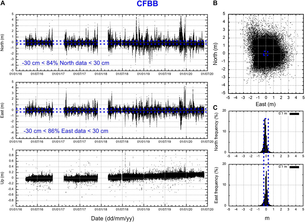
FIGURE 4. GPS kinematic time series (30 s sampling) of the CFBB station. (A) North (top row), East (middle row) and Up (bottom row) components; (B) GPS kinematic positions shown in the horizontal plane; (C) Frequency histogram of the horizontal components. Over 85% of the horizontal positions of the buoy are within 30 cm of the origin, taken as the mean horizontal position in the considered period.
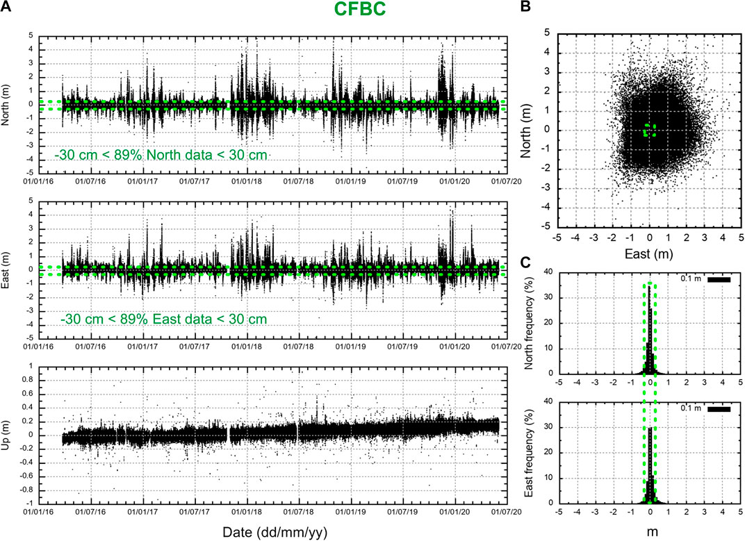
FIGURE 5. GPS kinematic time series (30 s sampling) of the CFBC station. (A) North (top row), East (middle row) and Up (bottom row) components; (B) GPS kinematic positions shown in the horizontal plane; (C) Frequency histogram of the horizontal components. Over 90% of the horizontal positions of the buoy are within 30 cm of the origin, taken as the mean horizontal position in the considered period.
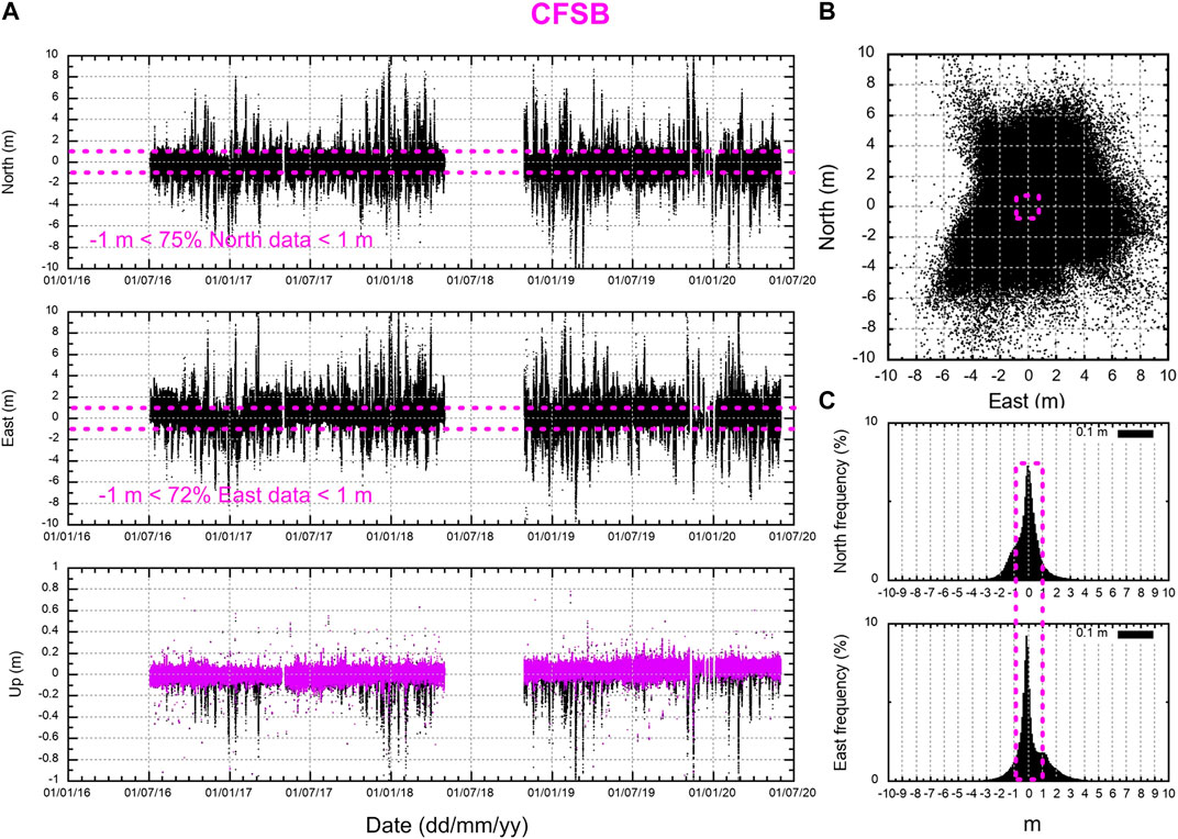
FIGURE 6. GPS kinematic time series (30 s sampling) of the CFSB station. (A) North (top row), East (middle row) and Up (bottom row) components. In the Up plot are reported the raw data (black dots) superimposed to corrected data (magenta dots); (B) GPS kinematic positions shown in the horizontal plane; (C) Frequency histogram of the horizontal components. Only 70% of the horizontal positions of the buoy are within 1 m of the origin, taken as the mean horizontal position in the considered period.
Note the different scale for the signal on the horizontal components (North and East) with respect to the vertical component (Up). This difference shows the influence of weather and sea conditions and marine water circulation on the horizontal components (Figures 3B–6B) which produces large fluctuations of the GPS signal, about 10% of which are above about 30 cm. Consequently, we consider that under bad weather conditions the measurements of the position of the buoys is unreliable and we remove all data with fluctuations above ±30 cm in the North and East components. As shown in Figures 3C–5C, about 10–15% of horizontal positions at CFBA, CFBB and CFBC are outside ±30 cm of the corresponding origin (mean position in the considered period) and were discarded to reduce the noise in the North and East components for these stations. Moreover, Figures 3–6, shows that the amplitudes of the GPS horizontal displacements for the three newer buoys (CFBA, CFBB and CFBC stations) are about one third of those of the older CUMAS buoy (CFSB station). This difference is due to the improved design of the new buoys compared to CUMAS and also to the greater length of the CUMAS steel cable (see Table 1).
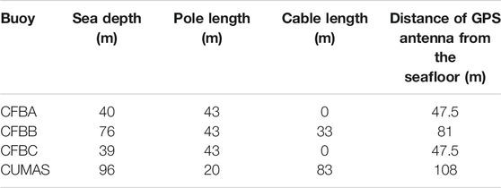
TABLE 1. Main physical characteristics of the buoys.
The CFSB station is characterized by a very high noise level (Figure 6) and so is not been included in the horizontal component analysis. Its vertical component has been corrected for vertical displacement induced by the horizontal movement of the buoy allowed by the long steel cable, as reported in De Martino et al. (2014a). This vertical correction is negligible for CFBA, CFBB and CFBC stations, due to the mechanical system adopted in the deployment of the three new buoys (Iannaccone et al., 2018).
In the Campi Flegrei caldera the deformation rates are relatively low (a few millimeters per month) and the trend of the displacement time-series can be best visualized with averaging to produce less frequent but more accurate positions (Larson et al., 2010). A weekly average is routinely applied (De Martino et al., 2014b) to data produced by the permanent Neapolitan Volcanic Continuous GPS (NeVoCGPS) network deployed on land (black circles in Figure 1. Here, for the MEDUSA data, we generate the weekly median time series of the cleaned kinematic solutions to which we applied an additional cleaning algorithm based on the interquartile range (IQR) statistic for outlier detection in the GPS position time series (Bock et al., 2000). An outlier is defined as having a residual with respect to the weekly median greater than 2 times the IQR. With this criterion, the algorithm removed about 5% of the kinematic data.
The weekly filtered GPS time series are shown in Figure 7. The uncertainties of the weekly positions (error bars) shown in Figure 7 represent the interquartile range (IQR) of each weekly median solution.
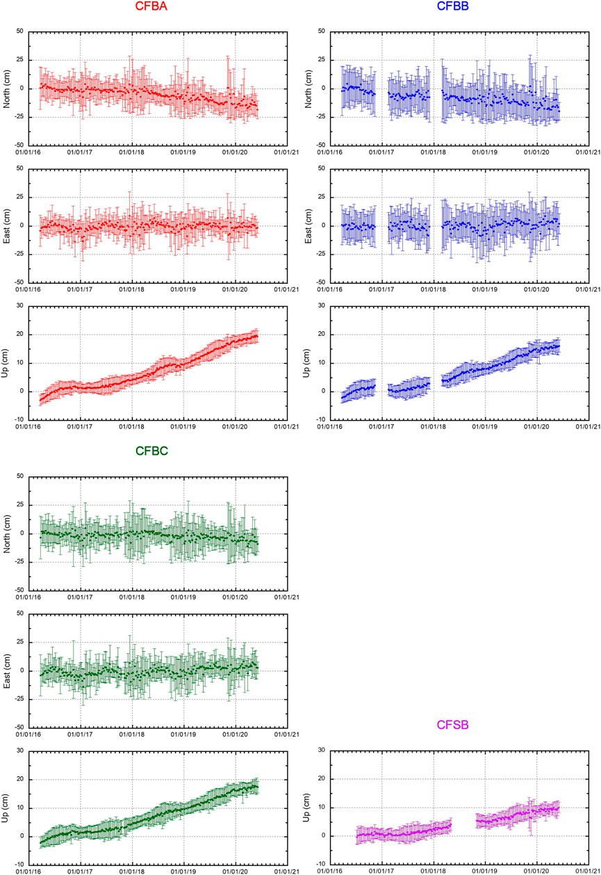
FIGURE 7. Weekly filtered GPS time series of stations CFBA, CFBB and CFBC (three components) and CFSB (Up component only). The error bars represent the interquartile range (IQR) of each weekly median solution.
In the considered period, the weekly time series show that the four buoys are subject to uplift and to radial horizontal movements with respect to the center of the caldera, as previously found by Iannaccone et al., 2018. Table 2 reports the correlation between the cGPS horizontal components of the couples of the buoys CFBA, CFBB and CFBC, in the period between 1 March 2018 and 31 May 2020.
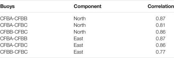
TABLE 2. Correlation between the cGPS horizontal components of the buoys CFBA, CFBB and CFBC in the period between 1 March 2018 and 31 March 2020.
We interpret the high correlation between the horizontal components as due to the effect of the wind and marine currents acting coherently on the three buoys CFBA, CFBB and CFBC. The buoy CFSB is located at greater depth and is subject to larger horizontal fluctuations. For this reason we have not performed the correlation analysis for CFSB.
Figure 8 shows the vertical displacement observed at the RITE cGPS station located in the town of Pozzuoli, the area of maximum vertical deformation of the caldera, and at the four MEDUSA cGPS stations on the buoys.
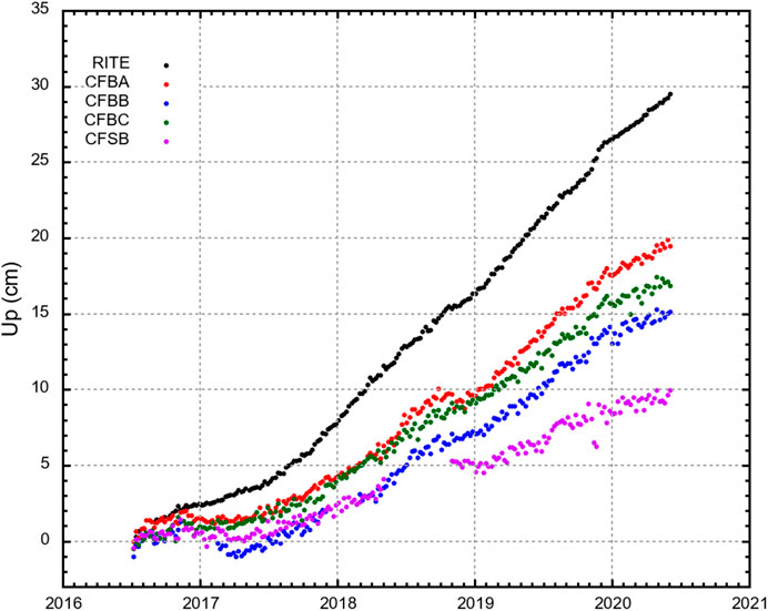
FIGURE 8. Weekly UP time series recorded by MEDUSA cGPS stations on the buoys compared to data observed in the maximum deformation area at the RITE cGPS station.
The consistency of the vertical displacement patterns between the stations is remarkable with a maximum uplift of the seafloor of about 20 centimeters at the CFBA station in the last four years and a decay of amplitude moving from the center to the border of the caldera.
Results
Recently, Iannaccone et al. (2018) demonstrated that a single Mogi model point source can explain both the onshore and seafloor deformation from cGPS data. They compared the expected vertical displacement in the marine sector to that predicted by a Mogi model computed using only horizontal and vertical, on-land, cGPS measurements in the period between April 2016 and July 2017. This period, however, was characterized by small vertical movements.
From July 2017 to May 2020, the Campi Flegrei caldera has been characterized by larger vertical motion with a constant, quasi-linear trend over time (http://www.ov.ingv.it/ov/it/bollettini/275.html). We use jointly the cGPS horizontal and vertical velocities of seafloor and onshore deformation for the modeling of the volcanic source.
The horizontal and vertical velocities, uncertainties, and noise properties were estimated from the weekly position time series of the 3 cGPS stations on the buoys (CFBA, CFBB and CFBC in Figure 7) and of the 21 cGPS stations deployed on land (De Martino et al., 2014b; Iannaccone et al., 2018), using the software package HECTOR (Bos et al., 2013). This software, based on the maximum likelihood estimation algorithm (MLE), estimates the linear trend in time series with temporally correlated noise. A flicker noise plus white noise model is assumed to take into account the existing noise signals in the time series and to compute more realistic uncertainties for the velocities (Mao et al., 1999; Williams 2008). An annual seasonal signal, partially caused by atmospheric loading, thermal expansion or multipath (Klos et al., 2018 and references therein), is estimated and removed.
The results of the velocity estimations are presented in Table 3 and Figure 9 (black arrows).
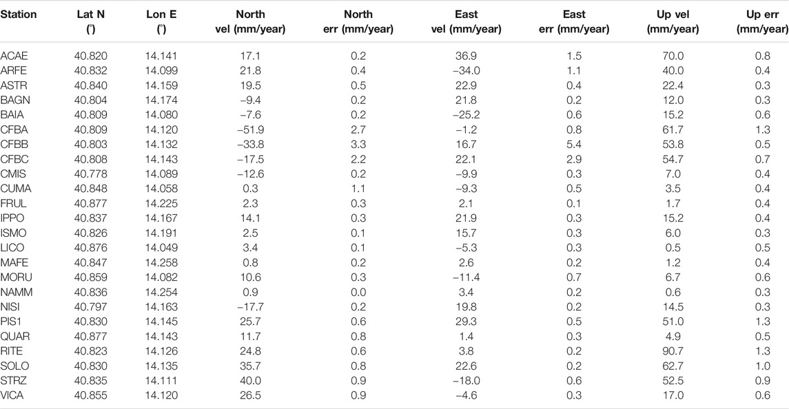
TABLE 3. cGPS station coordinates and component velocity and uncertainty from July 2017 to May 2020.
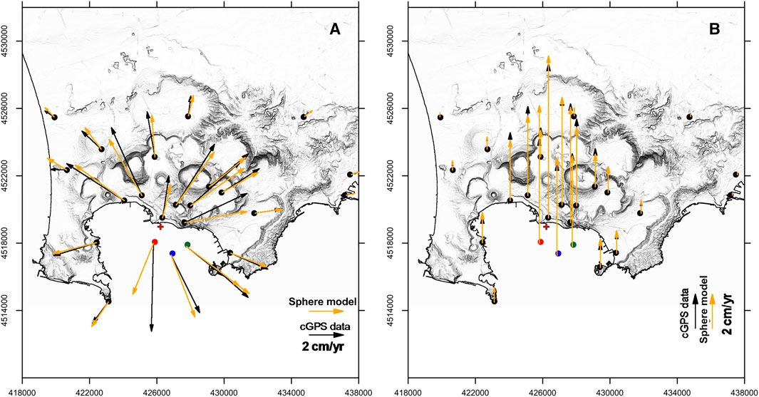
FIGURE 9. (A) Horizontal and (B) vertical cGPS velocity fields at Campi Flegrei caldera from July 2017 to May 2020. Black and orange arrows indicate observed (Table 3) and calculated displacements assuming a spherical source (Table 4), respectively. The location of the source is indicated by a red cross.
Next, we jointly inverted the horizontal and vertical deformation velocities measured at all the 24 cGPS stations (Figure 1) since July 2017 to investigate the caldera deformation. We used the dMODELS software package (Battaglia et al., 2013a; Battaglia et al., 2013b), which provides MATLAB functions and scripts to invert GPS data for the typical source shapes used in the volcanic environment (see eg: Gottsmann et al., 2006), such as spherical (McTigue, 1987), spheroidal (Yang et al., 1988) and sill (Fialko et al., 2001), embedded in a homogenous, isotropic, elastic half-space.
The results for different volcanic sources obtained by cGPS data inversion are listed in Table 4.
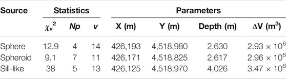
TABLE 4. Best fit parameters to cGPS data from Campi Flegrei caldera in Table 3.
The statistics shows that a spherical source (McTigue, 1987) fits best the GPS deformation velocities. The sill-like source has larger values of Np (number of source parameters) and χv2 (chi-squared per degrees of freedom) and the spheroid has a smaller value of χv2 than the spherical source but also has 3 additional geometrical parameters (Battaglia et al., 2013b).
Figure 9 shows the observed and calculated horizontal and vertical cGPS velocity field for the spherical source. The position of the best fit source to the cGPS data from July 2017 to May 2020 (red cross in Figure 9) is very similar to source position inferred by Iannaccone et al., 2018 in the time span April 2016 to July 2017.
Discussion and Conclusion
After a test period and four years of operation and improvement of the quality control and analysis procedures, the MEDUSA infrastructure now contributes continuous geodetic data to volcanological monitoring and studies of the marine sector of the Campi Flegrei caldera. A first set of long-term, geodetic time-series from July 2017 to May 2020 highlights the coherence of the deformation pattern across the marine and land areas.
The deformation field observed in the Campi Flegrei area is generally axi-symmetric with the maximum of vertical displacement measured at the RITE GPS station (Figure 1), at the center of the caldera (De Martino et al., 2014b). The vertical deformation decreases radially from the center and vanishes on the caldera’s border, about 6 km away. In this work we confirm a similar pattern is obtained with the joint use of marine and land GPS data. We demonstrated that a spherical source (McTigue, 1987) is in good agreement with both the vertical and the horizontal cGPS measurements.
This simple symmetric pattern would be perturbed if there were a lateral intrusion, such as a dyke, in the marine sector in the future. In this case, MEDUSA measurements would be essential for an early detection of an eventual magma rise in the marine sector of the caldera.
Despite the high noise level of the horizontal GPS components of MEDUSA, our results showing coherence with the corresponding onshore data indicate that useful signal can be obtained. However, the methodology we used for the recovery of the horizontal deformation components can be applied only after an observed monotonic trend of at least 1-year. This limitation implies that this method is not practical for real-time application, unless it is possible to achieve a higher accuracy and further reduce noise due to marine weather effects on the horizontal data.
Given the overall length of the buoys, from 47.5 to 108 m (see Table 1), it would be very difficult to decrease their movement in the sea. However, noise reduction through data position correction can be performed using heading, pitch and roll measurements produced by a digital compass on the top of each buoy. The MEDUSA infrastructure inspired the University of Southern Florida to build and deploy a similar buoy (SUBGEO-Shallow Underwater Buoy for Geodesy) in Tampa bay, Florida, at a water depth of about 23 m (Xie et al., 2019). Using a digital compass installed on the buoy, Xie et al. (2019) demonstrate the possibility to recover both horizontal and vertical components of the seafloor motion at the base of the buoy with an uncertainty of 1–2 centimeters.
Application of a similar procedure is under study for the MEDUSA buoys which also are equipped with digital compass to measure pitch, roll and heading data.
We have shown that MEDUSA provides continuous GPS measurements in shallow water (less than 100 meter depth) with a comparable precision to the land GPS vertical displacement and competitive with other systems such those using seafloor pressure gauges or GPS-acoustic positioning. The MEDUSA monitoring infrastructure is now permanently integrated into the multidisciplinary local monitoring network of Campi Flegrei and its data are routinely published within the periodical bulletins produced for the Italian Civil Protection Department and in the warning protocols in one of the highest risky area of the world.
Data Availability Statement
The datasets presented in this study can be found in online repository: http://portale.ov.ingv.it/medusa/download/four-years-of-continuous-seafloor-displacement-measurements.
Author Contributions
GI conceived the initial idea of the study, with all of the coauthors defining the methodology and strategy. SG, MD, and GD acquired cGPS data. PM provided the cGPS data processing, time series analysis (with contribution from GD, FC, and TT) and data modelling. GI, PM, and GM wrote the manuscript with input from all of the co-authors.
Funding
MEDUSA infrastructure was developed thanks to the financial support of the PAC01_00044-EMSO-MedIT project for the Enhancement of multidisciplinary marine research infrastructures in Southern Italy funded by MIUR (Ministry of Education, University and Research). We would like to acknowledge the support of the Contract INGV-DPC 2019-2021, Annex B2, Task 2: “Development of a real-time monitoring system for the ground deformation in the Neapolitan volcanic region using HR-GNSS measurements, and development of statistical and numerical models for the short-term vent opening probability in the Campi Flegrei caldera.”
Conflict of Interest
The authors declare that the research was conducted in the absence of any commercial or financial relationships that could be construed as a potential conflict of interest.
Acknowledgments
We thank all the INGV-OV staff involved in the management and maintenance of the MEDUSA infrastructure and cGPS network. This work was performed under the Agreement between Istituto Nazionale di Geofisica e Vulcanologia and the Italian Presidenza del Consiglio dei Ministri, Dipartimento della Protezione Civile (DPC). This paper does not necessarily represent DPC official opinion and Policies.
References
Battaglia, M., Cervelli, P. F., and Murray, J. R. (2013a). Modeling crustal deformation near activefaults and volcanic centers—a catalog of deformation models. U.S. Geological Sur-vey Techniques and Methods, 13 (B1), 75. Available at: pubs.usgs.gov/tm/tm13b1/
Battaglia, M., Cervelli, P. F., and Murray, J. R. (2013b). dMODELS: a MATLAB software package for modelling crustal deformation near active faults and volcanic centers. J. Volcanol. Geoth. Res. 254, 1–4. doi:10.1016/j.jvolgeores.2012.12.018
Bock, Y., Nikolaidis, R. M., de Jonge, P. J., and Bevis, M. (2000). Instantaneous geodetic positioning at medium distances with the Global Positioning System. J. Geophys. Res. 105 (B12), 28223–28253. doi:10.1029/2000JB900268
Bos, M. S., Fernandes, R. M. S., Williams, S. D. P., and Bastos, L. (2013). Fast error analysis of continuous GNSS observations with missing data. J. Geod. 87 (4), 351–360. doi:10.1007/s00190-012-0605-0
Bürgmann, R.,, and Chadwell, D. (2014). Sea floor geodesy. Annu. Rev. Earth Planet Sci. 42, 509–534. doi:10.1146/annurev‐earth‐060313‐054953
Chierici, F., Iannaccone, G., Pignagnoli, L., Guardato, S., Locritani, M., Embriaco, D., et al. (2016). A new method to assess long-term sea-bottom vertical displacement in shallow water using a bottom pressure sensor: application to Campi Flegrei, southern Italy. J. Geophys. Res.: Solid Earth 121, 7775–7789. doi:10.1002/2016JB013459
De Martino, P., Guardato, S., Tammaro, U., Vassallo, M., and Iannaccone, G. (2014a). A first GPS measurement of vertical seafloor displacement in the Campi Flegrei caldera (Italy). J. Volcanol. Geoth. Res. 276, 145–151. doi:10.1016/j.jvolgeores.2014.03.003
De Martino, P., Tammaro, U., and Obrizzo, F. (2014b). GPS time series at Campi Flegrei caldera (2000–2013). Ann. Geophys. 57 (2), S0213. doi:10.4401/ag-6431
Fialko, Y., Khazan, Y., and Simons, M. (2001). Deformation due to a pressurized horizontal circular crack in an elastic half-space, with applications to volcano geodesy. Geophys. J. Int. 146, 181–190. doi:10.1046/j.1365-246x.2001.00452.x
Gottsmann, J., Rymer, H., and Berrino, G. (2006). Unrest at the Campi Flegrei caldera (Italy): a critical evaluation of source parameters from geodetic data inversion. J. Volcanol. Geoth. Res. 50, 132–145. doi:10.1016/j.jvolgeores.2005.07.002
Iannaccone, G., Guardato, S., Donnarumma, G. P., De Martino, P., Dolce, M., Macedonio, G., et al. (2018). Measurement of seafloor deformation in the marine sector of the Campi Flegrei caldera (Italy). J. Geophys. Res. Solid Earth 123, 66–83. doi:10.1002/2017JB014852
Iannaccone, G., Guardato, S., Vassallo, M., Elia, L., and Beranzoli, L. (2009). A new multidisciplinary marine monitoring system for the surveillance of volcanic and seismic areas. Seismol Res. Lett. 80 (2), 203–213. doi:10.1785/gssrl.80.2.203
Iannaccone, G., Vassallo, M., Elia, L., Guardato, S., Stabile, T. A., Satriano, C., et al. (2010). Long-term seafloor experiment with the CUMAS module: performance, noise analysis of geophysical signals, and suggestions about the design of a permanent network. Seismol Res. Lett. 81, 916–927. doi:10.1785/gssrl.81.6.916
Klos, A., Bos, M. S., and Bogusz, J. (2018). Detecting time-varying seasonal signal in GPS position time series with different noise levels. GPS Solut. 22, 21. doi:10.1007/s10291-017-0686-6
Larson, K. M., Poland, M., and Miklius, A. (2010). Volcano monitoring using gps: developing data analysis strategies based on the June 2007 Kilauea volcano intrusion and eruption. J. Geophys. Res. Solid Earth 115 (B7), B07406. doi:10.1029/2009JB007022
Mao, A., Harrison, C. G. A., and Dixon, T. H. (1999). Noise in GPS coordinate time series. J. Geophys. Res.: Solid Earth 104, 2797–2816. doi:10.1029/1998JB900033
McTigue, D. F. (1987). Elastic stress and deformation near a finite spherical magma body resolution of the point source paradox. J. Geophys. Res. 92 (B12), 12931–12940. doi:10.1029/jb092ib12p12931
Petersen, F., Kopp, H., Lange, D., Hannemann, K., and Urlaub, M. (2019). Measuring tectonic seafloor deformation and strain-build up with acoustic direct-path ranging. J. Geodyn. 124, 14–24. doi:10.1016/j.jog.2019.01.002
Williams, S. D. P. (2008). Cats: gps coordinate time series analysis software. GPS Solut. 12, 147–153. doi:10.1007/s10291-007-0086-4
Xie, S., Law, J., Russell, R., Dixon, T. H., Lembke, C., Malservisi, R., et al. (2019). Seafloor geodesy in shallow water with GPS on an anchored spar buoy. J. Geophys. Res. Solid Earth 124 (11), 12116–12140. doi:10.1029/2019JB018242
Keywords: seafloor geodesy, volcano monitoring, Campi Flegrei caldera, Global Positioning System, time series, buoy
Citation: De Martino P, Guardato S, Donnarumma GP, Dolce M, Trombetti T, Chierici F, Macedonio G, Beranzoli L and Iannaccone G (2020) Four Years of Continuous Seafloor Displacement Measurements in the Campi Flegrei Caldera. Front. Earth Sci. 8:615178. doi: 10.3389/feart.2020.615178
Received: 08 October 2020; Accepted: 20 November 2020;
Published: 08 December 2020.
Edited by:
Keiichi Tadokoro, Nagoya University, JapanReviewed by:
Emily K. Montgomery-Brown, United States Geological Survey, United StatesMaurizio Battaglia, United States Geological Survey (USGS), United States
Copyright © 2020 De Martino, Guardato, Donnarumma, Dolce, Trombetti, Chierici, Macedonio, Beranzoli and Iannaccone. This is an open-access article distributed under the terms of the Creative Commons Attribution License (CC BY). The use, distribution or reproduction in other forums is permitted, provided the original author(s) and the copyright owner(s) are credited and that the original publication in this journal is cited, in accordance with accepted academic practice. No use, distribution or reproduction is permitted which does not comply with these terms.
*Correspondence: Giovanni Iannaccone, Z2lvdmFubmkuaWFubmFjY29uZUBpbmd2Lml0