 Paul-Ross Thomson
 Aizhan Aituar-Zhakupova
 Saswata Hier-Majumder
94% of researchers rate our articles as excellent or good
Learn more about the work of our research integrity team to safeguard the quality of each article we publish.
Find out more
ORIGINAL RESEARCH article
Front. Earth Sci., 08 June 2018
Sec. Solid Earth Geophysics
Volume 6 - 2018 | https://doi.org/10.3389/feart.2018.00058
This article is part of the Research TopicGeoscientific Visualization in Solid Earth GeophysicsView all 9 articles
We report the results of pore-network analysis of high resolution synchrotron microtomographic images of Fontainebleau and Berea Sandstones. We segment the gray-scale images of the rocks into constituent phases, and analyze the geometry of the pore network. The network consists of pores situated at the corner of grains and serve as the junction between elongated throats along grain edges. Our analysis indicates that the number of pores, their median coordination number, and fraction of connected pore space increases with an increase in porosity. In contrast, the width and length of throats decrease with an increase in total porosity. In each sample, the coordination number of pores is directly related to the radius of the pores, while the length of throats are also positively correlated with the throat radius. The permeability determined from the images increase with the total connected porosity of the samples and there is a change in the modeled permeability for each sample with flow direction. We observe that the dimensionless coefficient of variation of the throat lengths in all samples are nearly uniform around an average value of 0.64. The coefficient of variation of throat radii are generally higher than that of the radius of pores.
The flow of fluid in porous rocks is strongly controlled by both the total and interconnected porosity of the rock. In tight, low-porosity reservoirs, the issue of connected pore space becomes crucial while estimating the permeability and reservoir quality. A large number of studies on 2D and 3D image analysis and numerical models indicate that for a given pore volume, the degree of connectivity within a pore network plays a fundamental role in determining the effective transport and elastic properties of porous rocks (Von Bargen and Waff, 1986; Doyen, 1988; Lindquist et al., 2000; Bernabé et al., 2010; Wimert and Hier-Majumder, 2012; Miller et al., 2015).
Traditionally, porosity of reservoir rocks are estimated from laboratory experiments or various well logs such as sonic, resistivity, bulk porosity, and neutron porosity logs. While these logs can provide information about the total pore space in the reservoir, the extent of connectivity of pore space can not be calculated directly from these logs (Ellis and Singer, 2007; Rider and Kennedy, 2011). To estimate the extent of connected porosity and its effect on the permeability, rigorous characterization of pore-scale microstructure is necessary. A number of previous studies attempted to characterize the microstructure of rocks from high resolution 2D SEM images (Doyen, 1988; Yoshino et al., 2005). While useful in characterizing the dihedral angle of the fluids-solid junctions, these studies are unable to quantify the connectivity and distribution of the pore network in three dimensions.
The effectiveness of fluid transport in a porous rock depends both on the total porosity and the pore geometry. Pore space in rocks can be grouped into two entities, pores and throats (Lindquist et al., 2000; Youssef et al., 2007; Bernabé et al., 2010; Alyafei et al., 2013). The degree of connectivity of these entities in the network can be quantified by the coordination number, defined as the number of throats connected to a given pore (Figure 1d) (Lindquist et al., 2000). In addition, the width of the throats control the effective hydraulic radius of the rock. While these characteristic geometric features of the pore network can depend on a number of factors such as total porosity, degree of cementation, and the dihedral angle of the wetting fluid, it is desirable to identify universal traits of pore geometry which can be used to calculate effective physical properties of porous rocks (Bernabé et al., 2010). Detailed statistical analysis of three dimensional pore network geometry can identify such fundamental parameters describing these traits.
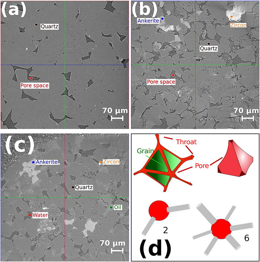
Figure 1. Microtomographic images of the slices of (a) dry Fontainebleau, (b) dry Berea, and (c) saturated Berea sandstones. The key mineral phases in each sample are clearly identified. (d) Simplified representations of the pore and throat geometry relationship. Throats are located along the edge of grains, while pores are located at the junction of grain to grain contacts. The spheres (pores) and cylinders (throats) represent an idealized model for the coordination number. As an example, we have shown here a coordination number of 2 and 6.
In rock physics, the role of pore network geometry is often addressed through empirically determined parameters, such as tortuosity. Often determined from fits to experimental data, such parameters lack a direct integration of measurable geometric properties of the pore space. Recent advances in synchrotron-based X-ray tomography allows a way to address this issue by characterizing pore network geometry from high resolution 3D images (Alyafei et al., 2013; Andrä et al., 2013; Madonna et al., 2013; Sharqawy, 2016). In one work, Bernabé et al. (2010) prescribe a “universal relationship” between the permeability of sandstones and the coordination number of pores. Such prescription of physical property in terms of pore geometry not only directly incorporates microstructural constraints but also allows calculation of permeability for problems such as migration of silicate melts in the Earth's mantle, where geometric parameters are available, but permeability experiments are not viable (Miller et al., 2015). Establishment of such quantitative relations can be developed in two steps: (a) Identifying the relations among parameters such as coordination number, pore and throat radii, throat length, and porosity and (b) quantifying a physical property, such as permeability over a large range of variations of these parameters to establish and test the quantitative relation.
In this article, we address the first part of this approach by providing a detailed recipe for image processing, characterizing pore network geometry, and determining the permeability through connected pore space. An earlier work of Lindquist et al. (2000) used synthetic and low resolution (5.7 μm voxel) tomographic images to characterize pore network geometry. Since throat radii often vary between 1 and 5 microns, proper identification of the smaller pores and throats and the statistical variations of these parameters was beyond the scope of their study. Later studies (Andrä et al., 2013; Madonna et al., 2013) used higher resolution microtomographic images, focusing on the effective physical properties of sandstone. Characteristics and variations in the parameters of pore network geometry was not addressed in these studies. In this article, we bridge the gap by carrying out a detailed analysis of pore network geometry using high resolution (0.74 μm voxel) images of sandstones used by Madonna et al. (2013).
An important step in characterizing the small scale microstructure is segmentation of microtomographic images. Efficient segmentation requires that meaningful regions of the image are extracted accurately. The goal of accurate segmentation is independent separation of phases of interest, in terms of similar brightness or color. It is important to segment key phases of the image correctly because the outcome can generate imprecise or wrong results. The literature reports numerous classical approaches to image segmentation, however there is not one single technique that is equally good for all types of image (Kaestner et al., 2008). We chose a simple yet popular method for image segmentation, with the use of thresholding.
In this work, we address the issue of how the fraction of connected pore space varies with total porosity, quantify the connectivity of the pores and throats as a function of total porosity, and quantify the permeability of these rocks. We take three different sandstone data sets to compare their porosities and absolute permeabilities. All samples were obtained using synchrotron radiation X-ray tomographic microscopy (SRXTM) after Madonna et al. (2013). Table 1 summarizes the characteristics of the raw data for all three cases.
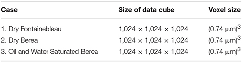
Table 1. Characteristics of raw data.
In section 2 we detail the methodology behind our work. We outline the filtering and segmentation stages of image preparation in section 2.1. We provide a description of the methods used to analyze the pore space in section 2.2. We define the fundamentals behind the Absolute Permeability Simulations in section 2.2.2. In section 3 we present the results from our work. We describe results from porosity analysis in section 3.1, pore network modeling in section 3.2, and permeability in section 3.3. In section 4 we discuss the outcome and relevance of our results. Finally, we summarize our work in section 5.
We use the open source tomographic images from Madonna et al. (2013) for the analysis in this work. The microtomographic images were acquired at the TOMCAT (TOmographic Microscopy and Coherent rAdiology experimenTs; Stampanoni et al., 2006) beam-line at the Swiss Light Source (SLS; Paul Scherrer Institute, Villigen, Switzerland). The tomographic volumes were reconstructed using a highly optimized algorithm based on Fourier methods (Marone et al., 2009). For detailed experimental parameters, refer to (Madonna et al., 2013).
We carried out a two-step analysis of the scanned microtomographic images. First, we filtered the 3D volume of gray scale images to remove artifacts and isolate the individual phases within the volume by the process of segmentation. We then analyzed the filtered and segmented images to determine the connectivity and characteristics of the pore network and simulate the flow of pore fluid through the interconnected pore spaces. The image analysis and simulation was carried out in the commercial software PerGeos, from Thermo Scientific. In section 2.1 we outline the details of the first step. In section 2.2 we present a detailed discussion about the methods used to analyze the pore space.
The unprocessed image in Figure 1 displays a number of unwanted artifacts and noise, including streaks, brightness non-uniformity and phase-contrast fringes at the grain edges. As individual phases (minerals and pore fluids) are segregated based on gray scale values, these artifacts can be erroneously ascribed to other phases or designated as new phases during segmentation. In order to avoid these errors, the artifacts need to be removed from 3D volume stack of unprocessed images. We extracted a sub volume of the data from the original volume reducing the number of image cube elements from 1,024 × 1,024 × 1,024 to 500 × 500 × 500. Selection of such a region of interest allows computational efficiency for detailed image filtering and simulations. We then processed the data with noise filtering and image segmentation.
We used the Interactive Top Hat (ITH) threshold filter in PerGeos to highlight the bright phase-contrast fringes found at the quartz grain boundaries. The process of selection of the fringes is outlined in Figure 2a. The final filtered image () is shown at different resolutions in Figures 3b,e. This filter detects the dark or white areas, which correspond to the valleys or peaks of the threshold histogram. We chose the White Top Hat option in PerGeos to select the bright fringes and assign the fringes a value of 1 in a resultant binary image, shown in Figure 2b, where all other regions were assigned a value of 0.
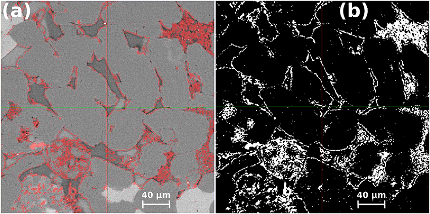
Figure 2. The ITH threshold filter on saturated Berea sandstone image slices 2D. (a) Selection of the bright phase-contrast fringes at the quartz grain boundaries. (b) Resultant binary image showing the bright fringes with a value of 1.
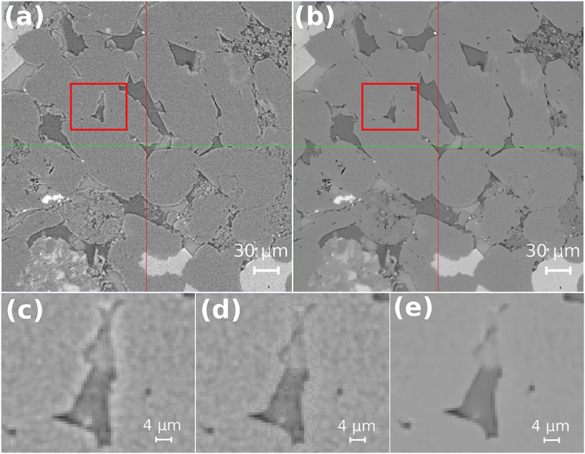
Figure 3. Noise filtering on saturated Berea sandstone image slice 2D. (a) Uncleaned image, (b) filtered image, (c) focused zoom of uncleaned image outlining bright fringes at grain boundaries, (d) focused zoom of uncleaned image showing the reduced brightness at grain boundaries and (e) focused zoom of filtered image showing little or no phase-contrast at quartz grain boundaries and reduced specular noise at grain interiors.
Once the binary image map of the bright fringes, , is created in Figure 2b we use it to subtract the excess brightness from the unprocessed image, , to obtain the filtered image, , using the formula,
The filter defined in the equation above is carried out as an element-wise matrix operation on each 2D image in the 3D volume stack. We use a constant value of , the difference between the median gray scale values of the interior of the quartz grains and the rim, derived from the unprocessed image. The image in Figure 3a shows , the unprocessed image, while the image in Figure 3c zooms inside the red rectangle in Figure 3a. The image in Figure 3d shows the same region from the image , with the bright fringe removed.
While the filter discussed above removes the bright rim, interior of the grains and pore spaces can contain specular noise. We chose the Non-Local Means (NLM) filter (Buades et al., 2008, 2010) to reduce this noise and smooth the images. This algorithm compares the neighborhoods of all voxels in a given search window with the neighbors of the current voxel in order to determine the new value for the current voxel. The similarity between the neighbors determines the weight with which the value of a voxel in the search window will influence the new value of the current voxel. The final weights are determined by applying a Gauss kernel to the similarity values. The resulting image contains less noise without significant loss of details. The images in Figures 3b,e show the result of processing the image, , with the NLM filter. The zoomed image in Figure 3e illustrates the uniform gray-scale values in the grain interior after application of the NLM filter.
Following the process of the filtering outlined above, there is now a clear contrast in brightness and color between key phases in the images (e.g., grain and water-saturated pore; Figure 3e). To segment the image, we manually selected the individual phases based on their gray-scale values. The image in Figure 4a outlines an example where the pore space is highlighted in blue after thresholding. Figure 4b shows the histogram plot for the gray scale range used to manually select the key phases in the image. Although the filter process is efficient and clear cut-offs can be derived based on the gray-scale values, a level of uncertainty still exists with thresholding as the selection of histogram ranges is dependent upon our own interpretation of each phase in the image (Saxena et al., 2017). To address this issue, we compared the output from another segmentation method, a semi-automatic threshold algorithm, the Marker-Based Watershed technique. We found that this algorithm provided an overestimation of one or more of the key phases in the image. Over segmentation is a common problem of watershed techniques (Haralick and Shapiro, 1985; Beucher, 1992), particularly when using data such as ours that has had significant beam hardening leading to significant image noise. In an attempt to counter this issue, the Marker-Watershed algorithm from PerGeos first generates a gradient from the original image as part of preprocessing before filling the pre-determined markers to complete the segmentation of all phases in the image. When comparing the segmentation results for the pore space volume in the saturated Berea sample, we found that the watershed technique overestimated the pore volume by 5% (24% compared to 19%). Our filtering and threshold segmentation results for the pore space volume matched closely with helium density and mercury porosimetry experiments carried out by Madonna et al. (2013) on the same rock sample. For this reason, we used the manual segmentation method throughout this work.
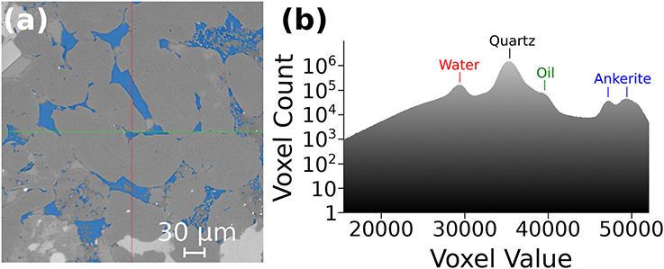
Figure 4. Interactive Threshold segmentation on saturated Berea sandstone filtered image slice 2D. (a) The selection of the pore space phase is shown here highlighted in blue. (b) The histogram range for the filtered image used to select separate phases.
While filtering and thresholding allowed smoothing, identification, and segmentation of individual phases, there were additional artifacts such as intragranular pits, which are incorrectly identified as pore space due to similar gray scale values. This feature was especially dominant in the sample of Fontainebleau sandstone. We carried out further thresholding of the Fontainebleau images to manually filter out these artifacts brushing noisy voxels slice by slice. Careful consideration was required to ensure that we did not remove voxels that were representative of the true pore space.
The primary objective of this article is to identify connected porosity, quantify the relationship between the attributes of pore geometry such as area and volume of pores, and calculate the permeability from the 3D volume stacks of filtered and segmented images. The first set of tasks are carried out by pore network modeling. After extracting the connected pore space by pore network modeling, we carried out numerical simulations of fluid flow through the 3D images of the connected pore space. Details of these two steps are discussed next.
Once the 3D image stacks are segmented into appropriate phases, we extract the pore phase for further analysis. Since the goal of this analysis is to quantify the geometry of the water-saturated pore, in the oil-bearing Berea sandstone, we selected only the water-saturated part of the pore space for further analysis. We discuss more about this issue in section 3.1. The pore network consists of two major components, pores and throats. In this model, linear throats are distributed along three grain junctions and connect with each other through the grain corner pores, which act as junctions. To identify the connected pore volume fraction and quantify the geometric parameters of the throats and pores, we used the pore network model (PNM) extension in PerGeos.
The PNM extension is based on a hybrid algorithm, detailed extensively by Youssef et al. (2007). The first step involves generating a one-voxel thick skeleton of the entire pore space. The skeletonization algorithm is developed from work involving micro-vascular network analysis (Fouard et al., 2004), and involves calculating the shortest distance of each point of the foreground (void space) to the background. The distance map (e.g., Fontainebleau sandstone, Figure 5a) is used to uniformly erode the pore-grain interface until the skeleton shown in Figure 5b is obtained. Next, the algorithm calculates the length and connectivity of each line. If an extreme radius (known from the distance map) of a line is larger than its length, then the line is classified as a pore, otherwise the line is designated as a throat (Youssef et al., 2007). At this stage, we calculate the coordination number — the number of throats connected to a given pore— for each pore, and identify the throats associated with each pore. Isolated pores and throats are grouped as unconnected pore space. The one voxel wide image is then expanded to fit the boundary of each pore and throat. During the expansion, we calculate the radius of a sphere that can fit within a pore and the length and equivalent hydraulic radius of each throat. The outcome of this process is two sets of data: (1) the coordination number, radius, area, and volume of each pore and (2) the radius and length of each throat. The labeled image in Figure 5c outlines the outcome of this process, with individual pores and throats colored differently.
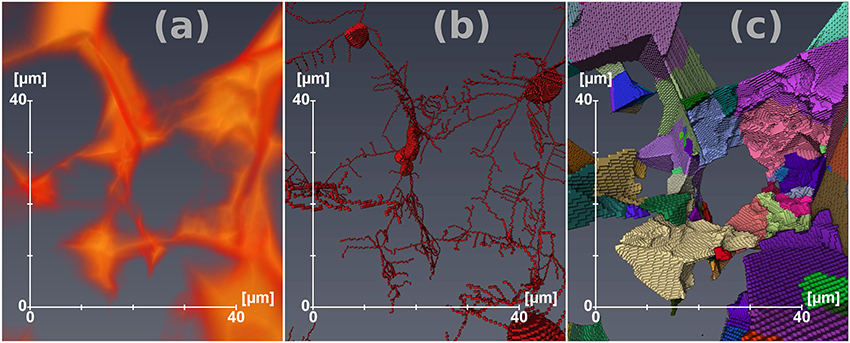
Figure 5. Steps involved in the generation of pore network models, shown here using the Fontainebleau pore network. (a) Distance map used to guide the thinning process. (b) One-voxel thick skeleton of the pore space. (c) Separated pore space image with individual pores and throats colored differently.
We calculate the permeability of the rock by simulating flow of water directly through the 3D images of the connected pore space obtained from the steps described above. Within the connected pore space, the flow of water can be described by Stokes equation,
where u is the fluid velocity vector, P is the pressure and μ = 1 × 10⁻³ Pa.s is viscosity of water.
We used the Absolute Permeability Experiment Simulation module in PerGeos to solve Equations (2) and (3), with a set of specified boundary conditions: a no-slip condition at fluid-solid interfaces, one voxel wide plane of a solid phase (with no-slip condition) is added on the faces of the image that are not perpendicular to the main flow direction, allowing isolation of the sample from the outside, and no flow out of the system. Experimental setups are added on the faces of the image that are perpendicular to the main flow direction, designed in a manner that creates a stabilization zone where pressure is quasi static, and the fluid can freely spread on the input face of the sample. Finally, two among the following three conditions can be chosen by the user, the third being estimated from the chosen two: input pressure, output pressure, flow rate.
We used a finite volume solver in the petrophysics module of PerGeos to solve for the unknowns, P and u. The governing partial differential equations are discretized on a staggered grid for pressure and velocity nodes, allowing a better estimation of the no-slip boundary condition. Pressure unknowns are located at the voxels center, whilst the velocity unknowns are decomposed at the faces of the voxels. The voxels are assumed isotropic (cubic) in the discretization scheme. We carried out a total of 27 numerical simulations for the three samples, varying the input pressure (P input) between 130, 150, and 200 kPa, while keeping the output pressure at a constant value of 100 kPa, to assess the influence of pressure gradient on permeability for three different flow directions (x, y, z).
We compare the porosity, PNMs and permeability for the three different sandstones. We show the total porosity and the difference between connected (effective) and unconnected (isolated) porosity for all examples. We also present the pore network of each sandstone, to compare and contrast characteristics of pores and throats. Finally, we highlight the results from absolute permeability simulations on each case and identify the preferential flow pathways through the samples.
Filtering, segmentation, and pore network analysis provides us with the volume fraction of constituent phases while separating connected porosity from isolated pore space. The 3D visualizations in Figure 6 demonstrate the results for the three cases. In Figure 6a we highlight the segmented phases in the saturated Berea sandstone by the color scheme: quartz (black), water (red), ankerite (blue), and oil (green). This visualization provides a representative view of the proportion of each phase in the sample. As the visualization demonstrates, quartz is the dominant phase, followed by water in the pore space. Table 2 lists the volume fraction of key phases in all samples. In the oil-bearing Berea sandstone, the pore-space contained two fluid phases, oil and water. Since our permeability simulation assumes the presence of only one fluid occupying the pore space, and we are interested in quantifying the connectivity of a single phase network, we only used the water-saturated porosity of this sample. The total physical porosity of this sample was 0.188, while the volume fraction of water-saturated porosity is 0.158. We report the latter porosity in Table 3, and use this water saturated pore space in the PNM analysis. Porosity and other pore-geometry related parameters for all three of these samples are described in Table 3.
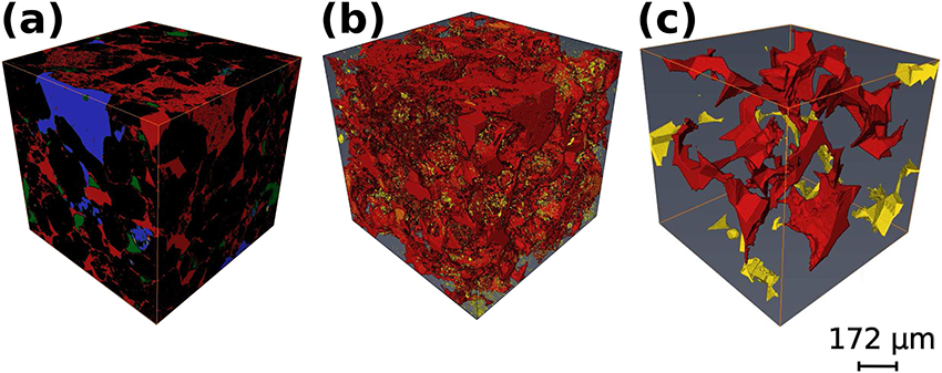
Figure 6. 3D volume rendering visualization of (a) saturated Berea sandstone with all phases: quartz (black), water (red), ankerite (blue), and oil (green). (b,c) Represent the connected (in red) and unconnected (in gold) pore spaces in the saturated Berea sandstone and Fontainebleau sandstone, respectively.
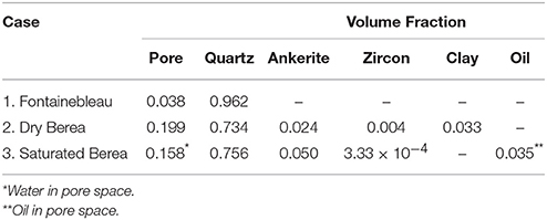
Table 2. Summary of the volume fraction of key phases in Fontainebleau, dry Berea, and saturated Berea sandstone.
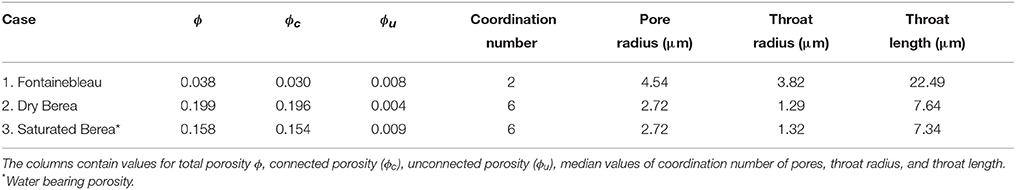
Table 3. Summary of pore network analysis of the three samples.
Connectivity of the pore space depends strongly on the total porosity. The two visualizations in Figures 6b,c depict the connected (in red) and unconnected (in gold) pore spaces in the dry Berea sandstone and the Fontainebleau sandstone, respectively. While only 0.3 vol% of the total of 20 vol% pore space of the Berea sandstone is isolated, the proportion of isolated to connected pore space is substantially higher in the Fontainebleau sandstone. Nearly a quarter (0.8 vol%) of the total porosity (3.8 vol%) in the Fontainebleau sandstone is isolated. As evidenced by the contrast in the size of the gold-colored pores between Figures 6b,c, the isolated pores in the Fontainebleau sandstone are fewer and larger compared to the Berea sandstone. This observation is similar to numerical models of synthetic pore network connectivity, where an increase in the pore volume leads to a reduction of isolated pore spaces (Von Bargen and Waff, 1986; Wimert and Hier-Majumder, 2012). We summarize the results of our porosity analysis in Table 3 with total, connected and unconnected porosity for all three sandstone examples.
The PNM segments the total pore space into a network of pores and throats. The pores, situated at the corner of four or more grains, act as junctions for throats, which are distributed typically along the contact between three grains. The visualizations in Figure 7 outline the pore network geometry for the two Berea sandstones and the Fontainebleau sandstone as a ball and stick model. In these visualizations, red spheres represent pores and gray cylinders represent the throats.
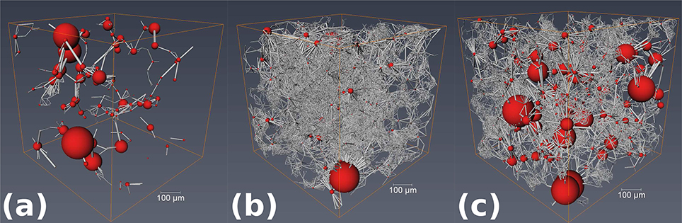
Figure 7. PNM visualization of the three different sandstones. Red spheres represent pores scaled with pore volume, while gray cylinders represent pore throats scaled with length. (a) Fontainebleau sandstone, (b) dry Berea sandstone, and (c) saturated Berea sandstone.
The visualizations in Figure 7 demonstrate a clear difference between the Fontainebleau (Figure 7a) and Berea sandstones (Figures 7b,c). The pore network of Fontainebleau sandstone is less dense, owing to the lower porosity, and consists of fewer larger throats connecting the pores. The network of both Berea sandstones are characterized by a dense mesh of smaller throats.
We compare the characteristics of the pore geometry for the three different sandstone cases: Fontainebleau, dry Berea, and saturated Berea in Figure 8. The probability distribution plots in Figures 8a–c depict the distributions of coordination number, throat length, and throat radius for the three cases, respectively. We report the median values for all three of these parameters in Table 3. The median coordination number for pores in both samples of the Berea sandstone is 6, compared to the median coordination number of 2 for the Fontainebleau sandstone. In addition, the pore network in both samples of the Berea sandstone consists of throats typically 1 μm in radius and 7–8 μm in length. In contrast, the pore network of Fontainebleau sandstones consists of larger throats, with a median radius of 4 μm and a length of 22 μm. The increase in median coordination number and decrease in median throat length with an increase in porosity in our samples agrees quite well with a similar trend observed by Lindquist et al. (2000).
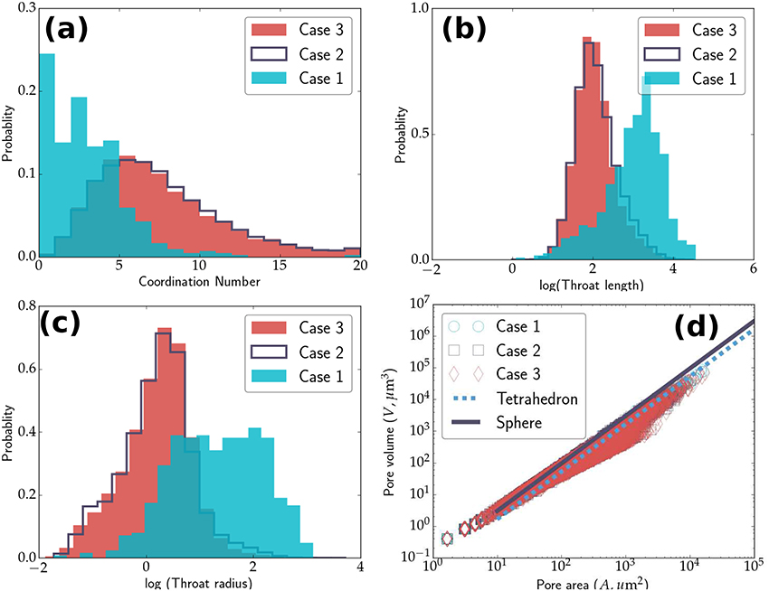
Figure 8. Plots comparing the PNM data for the three different sandstones. Fontainebleau (Case 1), dry Berea (Case 2), and saturated Berea (Case 3). (a) Probability distribution plot of coordination number of pores for the two Berea sandstone samples and the Fontainebleau sandstone sample. The median coordination number for both samples of Berea sandstones is 6, while that for Fontainebleau is 2. Probability distribution plots of throat length (b) and throat radius (c) for the same samples. (d) The relationship between the area and volume of all pores in all three samples. The surface area of majority of pores is larger than a sphere or tetrahedron, as expected.
The quantitative analysis of the throat geometry provides an important insight into the capacity of fluid transport by the pore network. The volumetric rate of fluid flow, Q, through a tube of radius r is, Q ∝ r4. As the results in Figures 8b,c indicate, the presence of such large throats gives the Fontainebleau sandstone a higher permeability, despite the relatively low porosity.
The plot in Figure 8d demonstrates the relationship between the area and volume of pores in all three samples. We also plot the volume-area relation for spheres and tetrahedra for comparison. For a given pore volume, the surface area of majority of the pores is larger than a sphere or a tetrahedron. This result is expected, as the sphere is the shape with the minimum surface area for a given volume, and pores are rarely spherical in shape. The departure of the data points from the tetrahedral geometry depicts that the shape of pores are also quite different from tetrahedra as often assumed in microstructure literature (Von Bargen and Waff, 1986).
To understand the nature of pore space connectivity, it is important to quantify the relation between major attributes of the pore geometry obtained from pore network modeling. The plots in Figure 9 outline the relationship between key parameters associated with pores and throats. To obtain these plots, we divided the data from each sample (for example, 22,224 pores and 91,604 throats from dry Berea sandstone) into 10 bins. The median values of each of these bins are then plotted, with the standard deviation within the bin as the error bar. The plot in Figure 9a display a clear positive correlation between the pores radius and coordination number, indicating that larger pores are connected to more throats. Comparison between the two rocks indicate that the slope of the plot is different. In Figure 9b throat length and radius in Berea sandstone also displays a clear correlation, indicating that longer throats are wider. This correlation, however, is less clear in the sample from the Fontainebleau sandstone, which shows a relatively lower variability in throat length, despite variations in the throat radius.
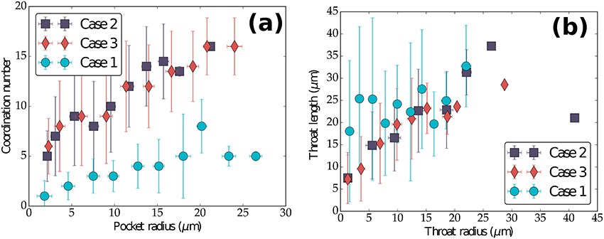
Figure 9. (a) Plot of pore coordination number as a function of pore radius, and (b) throat length as a function of throat radius. Each data point represents the median value of binned data. The error bars in the plots correspond to the standard deviation of the data in each bin. Fontainebleau (Case 1), dry Berea (Case 2), and saturated Berea (Case 3).
We show here a visual representation of the absolute permeability simulations for each of the sandstones cases. Figure 10 displays streamlines, colored by the magnitude of dimensionless fluid velocity, of fluid percolation through the connected pore space. Results of the absolute permeability simulations have been summarized in Table 4. We simulated a total of 27 experiments, varying the boundary condition input pressure (P input) between 130, 150, and 200 kPa to assess the influence of gradient change to permeability in all flow directions (x, y, z). Results confirm that there was no change to permeability with increased input pressure. Interestingly, there is a change to permeability for each sample with flow direction. The simulation results for permeability in Fontainebleau sandstone measure at 21.57, 11.02, and 14.80 mD, in the x, y and z flow directions respectively. We observe a permeability decrease of 49 and 31% in the y and z directions when compared to the x direction for this sample. The dry Berea sandstone shows a similar trend with permeability values in the x, y, z, directions of 166.9, 156.4, and 132 mD. This sample also shows a decrease in permeability when comparing flow in the x direction to y and z, with a reduction of 6 and 21% respectively. Our saturated Berea sample has differing permeability results when compared to our other sample of the same rock, the dry Berea. Simulation results in the x, y and z flow directions for this sample are 68.03, 61.48, and 116.3 mD. We note a similar reduction in permeability in the y direction compared to the x direction, with a decrease of 10%. However, there is an increase in permeability observed in the z direction, with a 71% change compared to the x direction.
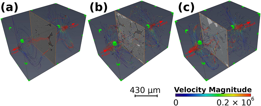
Figure 10. Absolute permeability simulations through (a) Fontainebleau sandstone, (b) dry Berea sandstone, and (c) saturated Berea sandstone. Areas with increased velocity are shown with red streamlines and are interpreted as preferential fluid flow pathways, whilst areas of reduced velocity magnitude are shown in blue.
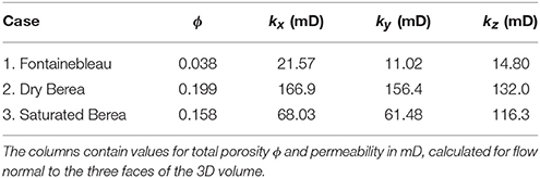
Table 4. Porosity and permeability values of the samples analyzed.
In the following section, we discuss the implications of our results and compare them with the results from previous studies on image analysis and laboratory experiments.
Our results on coordination number of pores agree well with previous studies involving image analysis and simulated microstructures. The plot in Figure 9A demonstrates that the coordination number of pores increase with the radius of the pore. Lindquist et al. (2000) carried out a similar pore network analysis on core samples of the Fontainebleau sandstone with porosities between 0.07 and 0.22. While the image resolution, segmentation, and skeletonization algorithm in their work was different from ours, they also observed an increase in average coordination number with an increase in pore radius and an increase in the median coordination number with porosity. As the pore volume fraction increases, the volume occupied by the pores also increases. Numerical simulations of pore geometry using level set methods (Ghanbarzadeh et al., 2015), surface tension minimization (Von Bargen and Waff, 1986), and steady-state microstructure (Wimert and Hier-Majumder, 2012) support this observation.
Another key feature of our observation involves the variations in length and radius of the throats. First, we note that the Fontainebleau sandstone is characterized by only 520 throats compared to more than 80,000 throats in each of the two samples of the Berea sandstone. While much fewer in number, the throats in the Fontainebleau sandstone are much wider and longer than those in the Berea sandstone, as shown in Table 3. In addition, the subvolume of Fontainebleau sample contains only 420 pores, while those of the Berea sandstone contains over 20,000 pores. Combined together, this result indicates that there are fewer junctions between the network of large conduits in the Fontainebleau sandstone, while the Berea sandstone consists of dense network of short, narrow throats, frequently joined by pores. This distinction between the two networks, visible in Figure 9, is also strongly supported by previous studies in image analysis (Lindquist et al., 2000) and numerical models (Von Bargen and Waff, 1986; Wimert and Hier-Majumder, 2012; Ghanbarzadeh et al., 2015).
One way of normalizing differences in results arising from image resolution and experimental errors is to identify dimensionless characteristic parameters of pore geometry. As these parameters are independent of methods of measurement, they are universal in nature. The generic relationship between these parameters and effective physical properties can be applied to a large variety of porous or fluid saturated multiphase aggregates. Such dimensionless parameters can be extremely useful in quantifying transport properties of deep mantle rocks containing partial melt, where the only estimate of pore fluid fraction can be obtained from seismic signals (Hier-Majumder and Revenaugh, 2010; Hier-Majumder, 2014; Miller et al., 2015; Hier-majumder and Tauzin, 2017).
Lindquist et al. (2000) presented a detailed study of various elements of pore geometry and their probability distribution. In a later work, Bernabé et al. (2010), expanded on this concept and identified two key dimensionless, universal parameters: coordination number of pores and the coefficient of variation of pore radius, σr/ ⟨r⟩. The data in Table 5 lists the coefficients of variation for pore and throat radii and throat length. We also calculated the hydraulic radius as the average of the maximum and minimum throat radii. The results from our PNM agree well with the compilation of Bernabé et al. (2010). For example, Bernabé et al. (2010) calculate σr/ ⟨r⟩ in the ranges 0.4–0.6 for pores and 0.7–0.8 for throats from the measurements of Doyen (1988) and Lindquist et al. (2000). With the exception of σr/ ⟨r⟩ for pores in the Fontainebleau sandstone, our other results are in good agreement with their finding. We also find a nearly uniform value of σl/ < l> for the throats in all samples. Despite the variations in porosity and mineral composition, the similarity between these values indicate that the coefficient of variation can act as a dimensionless, universal descriptor of pore geometry. Bernabé et al. (2010) identify that the permeability of porous rocks can be described as a function of coordination number of pores, hydraulic radius, and σr/ ⟨r⟩ from PNMs. These estimates can serve as an independent measure of permeability. Future work in characterizing such relations will be beneficial in digital rock physics analysis of permeability of porous crustal rocks as well as deep mantle rocks containing small amounts of melt.
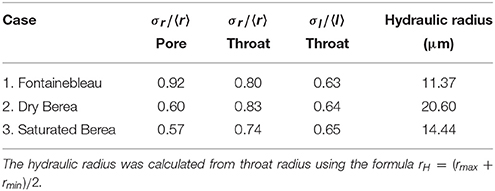
Table 5. Coefficients of variation for pore and throat radii and throat lengths for the three samples.
Finally, an important outcome of our analysis is the relationship between total porosity and isolated porosity. As results in Table 3 indicate, nearly 26% of the pore space in the Fontainebleau sandstone is unconnected, while the unconnected porosity in the Berea sandstone samples vary between 2 and 6%. Due to the presence of short grain edge throats, the grain corner pores in the higher porosity samples become better connected. This observation of higher pore connectivity at higher porosity strongly supports the theoretical models of pore networks using fluid mechanical and geometrical models (Von Bargen and Waff, 1986; Wimert and Hier-Majumder, 2012; Ghanbarzadeh et al., 2015).
The results from our permeability calculations are in agreement with the previous digital rock physics analysis by Andrä et al. (2013) and Sharqawy (2016). Both of these results also display general agreement with the experimental measurements by Yale (1984). As the plot in Figure 11 indicates, however, the numerical measurements from synchrotron microtomographic images (squares) can differ from experimental measurements (plotted as dots, Bourbié and Zinszner, 1985; Doyen, 1988; Gomez et al., 2010; Revil et al., 2014). One source of the disagreement between the numerical models and the experimental data can be the sample scale. Owing to the high resolution of the synchrotron microtomographic images, the volume for porous flow modeling is small. As a result, the volume used for permeability calculations from synchrotron images may not represent the full extent of heterogeneity in the rocks. From our results for the Fontainebleau sandstone we observe that the data lies to the left of the general trend for experimental data. A similar disagreement between numerical and experimental data has been highlighted in other work (Alyafei et al., 2013; Andrä et al., 2013), where their results show that lower-permeability sandstones, with more poorly connected pore networks, have simulated permeabilities that are much higher than the experimental core measurements for the same rock. This supports what we see from our PNM analysis of the Fontainebleau sandstone and helps provide a possible explanation for the location of the results in the plot (Figure 11). As this technique continues to develop, further future studies are needed to reconcile this disagreement between experimental measurements and digital rock physics analysis using high resolution images.
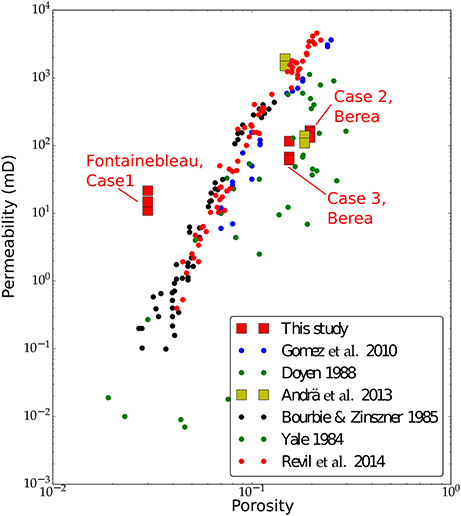
Figure 11. Log-log plot of permeability as a function of total porosity from our measurements with numerical models of Andrä et al. (2013), and experimental measurements of Doyen (1988), Bourbié and Zinszner (1985), Yale (1984), and Gomez et al. (2010). Data points corresponding to the three cases studied here are annotated in the figure. Numerical values of the data points from this study are provided in Table 4.
Our results also demonstrate anisotropic permeability, which is observed in all of our samples. Knowledge of such variation with flow direction is crucial for reservoir engineering and hydrocarbon recovery applications. We see that our results share some similarities with other work looking at the multidirectional variation of permeability (Clavaud et al., 2008; Peyman and Apostolos, 2017). However, we also note from our results that the difference in permeability with flow direction differs from results obtained by Peyman and Apostolos (2017) on the same Berea sandstone. Their results indicate a permeability decrease in the y and z-directions of 23 and 21%, respectively. From our simulations we have permeability reductions in the y and z-directions of 6 and 21% for the dry Berea. Whilst the saturated Berea shows a decrease in the y-direction with a 10% drop, the z-direction shows a percentage increase of 71%. Our samples may be more or less heterogeneous in particular flow directions, which is one possible reason behind this variation in permeability. The voxel resolution can also produce relatively large variation in flow properties (Saxena et al., 2017), which may also explain what we see when comparing our results to other work. It has been pointed out in previous work by Wright et al. (2006), that a possible explanation for anisotropic permeability in sandstones is due to the orientation of mineral grains and pores. We suggest future work using numerical methods to evaluate the influence of grain and pore orientation on permeability in different flow directions.
Our results have implications for the production of hydrocarbons in the oil and gas industry. Although the size of our data samples are small and therefore may not represent the true reservoir heterogeneity, permeability results give an indication to overall preferential flow direction. A study involving the acquisition and processing of numerous samples from various horizons in the reservoir would provide useful information to evaluate the permeability anisotropy at a larger scale. As techniques in digital rock physics continue to develop, further work is required to investigate the relationship between grain/pore orientation and anisotropic permeability. A comparison using numerical methods, combined with samples at a range of different resolutions would provide valuable information to this line of research. This will aid in our understanding of reservoir heterogeneity and will help researchers assess the most efficient techniques for comparison to traditional experimental and well test measurements.
We find that our combination of image filtering and threshold segmentation methods provide meaningful and acceptable results for pore geometry analysis and single phase fluid flow modeling using micro tomographic images with multiple phases and significant noise. As the porosity increases from 4% to 16%, the median coordination number of pores increases from 2 to 6. The lower porosity Fontainebleau sandstone is characterized by fewer, larger pores and throats (pore radius 4.5 μ m and throat radius 3.8 μ m). In contrast, both samples of the Berea sandstone are characterized by a dense network of numerous smaller pores (~2.7 μm radius) and throats (~1.3 μm radius). We also observe a decrease in isolated pore space with an increase in porosity, resulting in a higher coordination number of the Berea sandstone. Fluid flow simulations highlight anisotropic permeability which is probably due to heterogeneity in the sample, more than likely caused by the variation in orientation of grains and pores in each direction.
The raw 3D Images used in this work were downloaded from the ETH Zürich Rock Physics Network. The pore network modeling data sets GENERATED for this study can be found in the Zenodo repository (Thomson et al., 2018a). Segmented images of the pore network GENERATED for this study can be found in the Figshare repository (Thomson et al., 2018b).
P-RT carried out the image segmentation and permeability simulations in all samples. AA-Z carried out initial segmentation, permeability calculation, and pore network modeling in samples for the Fontainebleau and dry Berea sandstones. SH-M and P-RT jointly carried out the final pore-network modeling and statistical analysis. All three authors contributed to writing and revision of the manuscript.
P-RT acknowledges support from a NERC Oil and Gas CDT graduate fellowship (grant number NE/M00578X/1).
The authors declare that the research was conducted in the absence of any commercial or financial relationships that could be construed as a potential conflict of interest.
AA-Z was funded by the Bolashak scholarship from the Kazakhstani Government. Financial support for this research was provided by RHUL internal funding.
Alyafei, N., Ic, I. C., Gharbi, O., Raeini, A. Q., and Yang, J. (2013). IPTC 16600 Influence of Micro-Computed Tomography Image Resolution on the Predictions of Petrophysical Properties (Beijing).
Andrä, H., Combaret, N., Dvorkin, J., Glatt, E., Han, J., Kabel, M., et al. (2013). Digital rock physics benchmarks-Part I: imaging and segmentation. Comp. Geosci. 50, 25–32. doi: 10.1016/j.cageo.2012.09.005
Bernabé, Y., Li, M., and Maineult, A. (2010). Permeability and pore connectivity: a new model based on network simulations. J. Geophys. Res. Solid Earth 115, 1–14. doi: 10.1029/2010JB007444
Beucher, S. (1992). “The watershed transformation applied to image segmentation,” in Proceedings of the 10th Pfefferkorn Conference on Signal and Image Processing in Microscopy and Microanalysis, 299–314.
Bourbié, T., and Zinszner, B. (1985). Hydraulic and acoustic properties as a function of porosity in Fontainebleau Sandstone. J. Geophys. Res. 90, 11524–11532. doi: 10.1029/JB090iB13p11524
Buades, A., Coll, B., and Morel, J. M. (2008). Nonlocal image and movie denoising. Int. J. Comput. Vis. 76, 123–139. doi: 10.1007/s11263-007-0052-1
Buades, A., Coll, B., and Morel, J. M. (2010). Image denoising methods. A new nonlocal principle. SIAM Rev. 52, 113–147. doi: 10.1137/090773908
Clavaud, J. B., Maineult, A., Zamora, M., Rasolofosaon, P., and Schlitter, C. (2008). Permeability anisotropy and its relations with porous medium structure. J. Geophys. Res. Solid Earth 113, 1–10. doi: 10.1029/2007JB005004
Doyen, P. M. (1988). Permeability, conductivity, and pore geometry of sandstone. J. Geophys. Res. 93:7729. doi: 10.1029/JB093iB07p07729
Fouard, C., Malandain, G., Prohaska, S., Westerhoff, M., Cassot, F., Mazel, C., et al. (2004). “Skeletonization by blocks for large 3D datasets: application to brain microcirculation,” in 2004 2nd IEEE International Symposium on Biomedical Imaging: Macro to Nano (IEEE Cat No. 04EX821) 2, 89–92. doi: 10.1109/ISBI.2004.1398481
Ghanbarzadeh, S., Hesse, M. A., and Prodanović, M. (2015). A level set method for materials with texturally equilibrated pores. J. Comput. Phys. 297, 480–494. doi: 10.1016/j.jcp.2015.05.023
Gomez, C. T., Dvorkin, J., and Vanorio, T. (2010). Laboratory measurements of porosity, permeability, resistivity, and velocity on Fontainebleau sandstones. Geophysics 75:E191. doi: 10.1190/1.3493633
Haralick, R. M., and Shapiro, L. G. (1985). Image segmentation techniques. Comput. Vis. Graph. Image Process. 29, 100–132. doi: 10.1016/S0734-189X(85)90153-7
Hier-Majumder, S. (2014). Melt redistribution by pulsed compaction within ultralow velocity zones. Phys. Earth and Planet. Int. 229, 134–143. doi: 10.1016/j.pepi.2014.01.004
Hier-Majumder, S., and Revenaugh, J. (2010). Relationship between the viscosity and topography of the ultralow-velocity zone near the core-mantle boundary. Earth Planet. Sci. Lett. 299, 382–386. doi: 10.1016/j.epsl.2010.09.018
Hier-majumder, S., and Tauzin, B. (2017). Pervasive upper mantle melting beneath the western US. Earth Planet. Sci. Lett. 463, 25–35. doi: 10.1016/j.epsl.2016.12.041
Kaestner, A., Lehmann, E., and Stampanoni, M. (2008). Imaging and image processing in porous media research. Adv. Water Resour. 31, 1174–1187. doi: 10.1016/j.advwatres.2008.01.022
Lindquist, W., Venkatarangan, A., Dunsmuir, J., and Wong, T. (2000). Pore and throat size distributions measured from synchrotron X-ray tomographic images. J. Geophys. Res. Solid Earth 105, 21509–21527. doi: 10.1029/2000JB900208
Madonna, C., Quintal, B., Frehner, M., Almqvist, B. S. G., Tisato, N., Pistone, M., et al. (2013). Synchrotron-based X-ray tomographic microscopy for rock physics investigations. Geophysics 78, D53–D64. doi: 10.1190/geo2012-0113.1
Marone, F., Hintermuller, C., McDonald, S., Abela, R., Mikuljan, G., Isenegger, A., et al. (2009). X-ray tomographic microscopy at TOMCAT. J. Phys. Conf. Ser. 186, 5–8. doi: 10.1088/1742-6596/186/1/012042
Miller, K. J., Montési, L. G., and Zhu, W.-l. (2015). Estimates of olivine-basaltic melt electrical conductivity using a digital rock physics approach. Earth Planet. Sci. Lett. 432, 332–341. doi: 10.1016/j.epsl.2015.10.004
Peyman, M., and Apostolos, K. (2017). “SPE-185720-MS DyMAS: a direct multi-scale pore-level simulation approach,” in SPE Western Regional Meeting (Society of Petroleum Engineers), 1–15
Revil, A., Kessouri, P., and Torres-Verdín, C. (2014). Electrical conductivity, induced polarization, and permeability of the Fontainebleau sandstone. Geophysics 79, D301–D318. doi: 10.1190/geo2014-0036.1
Saxena, N., Hofmann, R., Alpak, F. O., Dietderich, J., Hunter, S., and Day-Stirrat, R. J. (2017). Effect of image segmentation & voxel size on micro-CT computed effective transport & elastic properties. Mar. Petrol. Geol. 86, 972–990. doi: 10.1016/j.marpetgeo.2017.07.004
Sharqawy, M. H. (2016). Construction of pore network models for Berea and Fontainebleau sandstones using non-linear programing and optimization techniques. Adv. Water Resour. 98, 198–210. doi: 10.1016/j.advwatres.2016.10.023
Stampanoni, M., Groso, A., Isenegger, A., Mikuljan, G., Chen, Q., Bertrand, A., et al. (2006). Trends in Synchrotron-Based Tomographic Imaging: The SLS Experience. International Society for Optics and Photonics.
Thomson, P.-R., Aituar-Zhakupova, A., and Hier-Majumder, S. (2018a). Pore Network Modeling Data for Fontainebleau and Berea Sandstones. Zenodo 25:1184144. doi: 10.5281/zenodo.1184144
Thomson, P.-R., Aituar-Zhakupova, A., and Hier-Majumder, S. (2018b). Segmented Image Data for Fontainebleau and Berea Sandstones. Zenodo. Available online at: https://figshare.com/articles/Segmented_Image_Data_for_Fontainebleau_and_Berea_Sandstones/6154811
Von Bargen, N. and Waff, H. S. (1986). Permeabilities, interfacial areas and curvatures of partially molten systems: results of numerical computations of equilibrium microstructures. J. Geophys. Res. 91, 9261–9276. doi: 10.1029/JB091iB09p09261
Wimert, J., and Hier-Majumder, S. (2012). A three-dimensional microgeodynamic model of melt geometry in the Earth's deep interior. J. Geophys. Res. 117:B04203. doi: 10.1029/2011JB009012
Wright, H. M., Roberts, J. J., and Cashman, K. V. (2006). Permeability of anisotropic tube pumice: model calculations and measurements. Geophys. Res. Lett. 33, 2–7. doi: 10.1029/2006GL027224
Yale, D. (1984). Network Modeling of Flow, Storage, and Deformation in Porous Rocks. Ph.D. thesis, Stanford University.
Yoshino, T., Takei, Y., Wark, D. A., and Watson, E. B. (2005). Grain boundary wetness of texturally equilibrated rocks, with implications for seismic properties of the upper mantle. J. Geophys. Res. B Solid Earth 110, 1–16. doi: 10.1029/2004JB003544
Youssef, S., Rosenberg, E., Gland, N., Kenter, J., Skalinski, M., and Vizika, O. (2007). “High resolution CT and pore-network models to assess petrophyscial properties of homogeneous and heterogeneous carbonates,” in PE/EAGE Reservoir Characterization and Simulation Conference (Society of Petroleum Engineers).
Keywords: digital rock physics, porosity, sandstone, microfluid, petrophysics
Citation: Thomson P-R, Aituar-Zhakupova A and Hier-Majumder S (2018) Image Segmentation and Analysis of Pore Network Geometry in Two Natural Sandstones. Front. Earth Sci. 6:58. doi: 10.3389/feart.2018.00058
Received: 26 February 2018; Accepted: 07 May 2018;
Published: 08 June 2018.
Edited by:
Marie Estelle Solange Violay, École Polytechnique Fédérale de Lausanne, SwitzerlandReviewed by:
Beatriz Quintal, Université de Lausanne, SwitzerlandCopyright © 2018 Thomson, Aituar-Zhakupova and Hier-Majumder. This is an open-access article distributed under the terms of the Creative Commons Attribution License (CC BY). The use, distribution or reproduction in other forums is permitted, provided the original author(s) and the copyright owner are credited and that the original publication in this journal is cited, in accordance with accepted academic practice. No use, distribution or reproduction is permitted which does not comply with these terms.
*Correspondence: Saswata Hier-Majumder, c2Fzd2F0YS5oaWVyLW1hanVtZGVyQHJodWwuYWMudWs=
Disclaimer: All claims expressed in this article are solely those of the authors and do not necessarily represent those of their affiliated organizations, or those of the publisher, the editors and the reviewers. Any product that may be evaluated in this article or claim that may be made by its manufacturer is not guaranteed or endorsed by the publisher.
Research integrity at Frontiers
Learn more about the work of our research integrity team to safeguard the quality of each article we publish.