- Center for Advanced Marine Core Research, Kochi University, Nankoku, Japan
This study proposes a new method for measuring transient magnetization of natural samples induced by a pulsed field with duration of 11 ms using a pulse magnetizer. An experimental system was constructed, consisting of a pair of differential sensing coils connected with a high-speed digital oscilloscope for data acquisition. The data were transferred to a computer to obtain an initial magnetization curve and a descending branch of a hysteresis loop in a rapidly changing positive field. This system was tested with synthetic samples (permalloy ribbon, aluminum plate, and nickel powder) as well as two volcanic rock samples. Results from the synthetic samples showed considerable differences from those measured by a quasi-static method using a vibrating sample magnetometer (VSM). These differences were principally due to the time-dependent magnetic properties or to electromagnetic effects, such as magnetic viscosity, eddy current loss, or magnetic relaxation. Results from the natural samples showed that the transient magnetization–field curves were largely comparable to the corresponding portions of the hysteresis loops. However, the relative magnetization (scaled to the saturation magnetization) at the end of a pulse was greater than that measured by a VSM. This discrepancy, together with the occurrence of rapid exponential decay after a pulse, indicates magnetic relaxations that could be interpreted in terms of domain wall displacement. These results suggest that, with further developments, the proposed technique can become a useful tool for characterizing magnetic particles contained in a variety of natural materials.
Introduction
Pulse magnetizers have been used in rock magnetic studies because they produce a high magnetic field without the need for a large electromagnet. This allows for rapid acquisition of isothermal remanent magnetization (IRM) over a short (<1 s) period of time. Stepwise IRM acquisition curves are used to identify magnetic minerals with different coercivities; IRM unmixing analysis (Kruiver et al., 2001; Heslop et al., 2002; Egli, 2003, 2004) has often been used as a convenient means for the identification and quantification of magnetic minerals in a sample (e.g., Abrajevitch and Kodama, 2011).
Since its invention by Kapitza (1924), the pulse magnetizer has been used more frequently in experimental magnetism and material research than in rock magnetism. In modern physics laboratories, such systems can readily generate high fields reaching 100 T (e.g., Miura, 2007). Using an apparatus comprising a pulse magnet and a sensing coil system, a number of studies have been carried out for the characterization of ferromagnetic materials. The apparatus measures the dynamic response of magnetic properties such as hysteresis loops, magnetostriction, and magneto–optical spectroscopy (e.g., Grössinger et al., 1993; Dudding et al., 2002; Ludwig et al., 2002; Nojiri et al., 2007; Prieto Astalan et al., 2007).
The largest field required for rock magnetism measurements is 10 T. Thus, a compact and inexpensive instrument such as a pulse magnet is invaluable. Several commercial systems are available for imparting IRM or saturation IRM to natural samples. However, the typical magnetization of natural samples is much weaker than that of synthetic ferromagnetic materials. Thus, the techniques and analyses employed in conventional pulsed field magnetometry cannot be readily applied to rock magnetism investigations. However, thanks to the recent development of digital signal processing and fast broadband digital oscilloscopes, it is possible to construct a simple, sensitive, and cost-effective system without employing complicating electronics. This allows high-speed measurements of the dynamic magnetization behaviors of natural samples. This study describes the apparatus and measurement procedures of such a system dedicated to rock magnetism investigations and reports the dynamic magnetic behaviors obtained from a set of synthetic materials and natural samples. These results are discussed in comparison with those obtained by conventional rock magnetism methods.
Experiment
Instrument and Method
The measurement system consists of a pulse magnetizer, a sensing coil system embedded in the sample cavity of the pulse magnet, and a high-speed digital oscilloscope for recording the coil outputs (Figure 1). The pulse magnetizer used in this study is the commercially available ASC IM10-30 impulse magnetizer (ASC Scientific, USA). The maximum peak field depends on an exchangeable coil. In this study, we used a 2-inch-diameter coil that is capable of producing a pulsed field of 0.3–1.3 T with a sample cavity large enough to accommodate the sensing coil system. The digital oscilloscope is an Keysight DSO 9104A, a two-channel oscilloscope with 1 GHz bandwidth and 2 MB memory. Data acquisition is triggered by a pulsed field, and the captured data are transmitted to an external computer for digital processing. Processing is accomplished by programs written in LabVIEW and MATLAB. Additional measurements with a MircoMag 3900 vibrating sample magnetometer (VSM; Lake Shore, USA) were made for comparison.
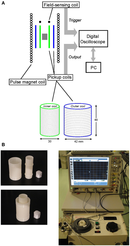
Figure 1. (A) Schematic diagram of the measurement system. (B) (Left) Photos of the inner and outer pick-up coils (top) and the assembled system (bottom), with a 7-cc cube for scale. (Right) an overview of the measurement system. A field-sensing coil is placed at the bottom of the sample cavity of IM10-30 pulse magnetizer.
The pick-up coil system consists of two series-connected coaxial coils wound in opposite directions to sense the magnetization induced by a pulsed field. In the absence of a sample, the magnetic flux density B (Wb/m2) inside the sensing coil is μH, where H (A/m) is the pulse magnetic field and μ (H/m) is the magnetic permeability of air. Since μ is equivalent to the magnetic permeability in free space μ0 (= 4π× 10−7), B is usually written as B = μ 0H. When inserting a sample in the coil system and applying a pulsed field H, the instantaneous flux density B over the volume of the sample changes from μ0H to
where M is the magnetization of the sample induced by the pulse. Because the sample has a finite length and a specific shape, such as cylinder or cube, M is a function of not only the intrinsic magnetization of the sample but also the shape and volume of the sample. The voltage output V of the sensing coil is proportional to the time derivative of Equation (1), i.e.,
Thus, if the sensing coil is compensated to make its output zero in the absence of the sample, the first term of Equation (2) is zero and the integration of V provides a quantity proportional to M.
To compensate the sensing coil within the limitations imposed by the sample cavity of the IM10-30, we adopted the concentric configuration shown in Figure 1, a radial gradient coil system often used in experimental magnetism (e.g., Grössinger et al., 1993; Dudding et al., 2006). The coils have equal length and are wound using 0.1-mm-diameter copper wire, with turns of No = 476 and Ni = 952 and diameters of 30 and 42 mm (= 30× ), respectively, to achieve the equal turns-area products leading to compensation of the magnetic flux detected by the coil system. The turns-area products are equal because the area ratio of the outer and inner coils is 2/1, and the ratio of their turns, No/Ni, is 1/2. To further compensate for small residual contributions from the pulse due to incomplete compensation of the coaxial coils, a small coil (10 turns) is connected in series. Its output is adjusted using a potentiometer, such that the integration of the output of the coil system (coaxial coils plus compensation coil) in the absence of a sample approaches to zero.
A measurement is triggered when a pulse signal is sent to channel 1 (CH1) of the oscilloscope from a field-sensing coil (five turns). The output from the pick-up coil system is then transferred to channel 2 (CH2). The data are captured at a sampling rate of 20 M Sa/s (= 2 × 10⁷ sample/s). A screenshot of the oscilloscope from the field-sensing coil for one pulse is presented in Figure 2, showing the direct output in mV from the field-sensing coil (yellow curve) and its integration with respect to time (white curve) obtained simultaneously using the oscilloscope functions. The integrated curve corresponds to the pulsed field, showing the shape of one-half cycle of damped oscillation with a width of 11 ms. This wave form is typical for a pulsed field that is generated by a sudden discharge of a large capacitor bank. The pulse duration is determined by the resonant frequency of the LC circuit, or 2π /(LC)1/2, where C is the capacitance of the capacitor bank and L is the impedance of the pulse magnet coil. Due to the DC resistance of the circuit, the shape of the pulse in Figure 2 is slightly asymmetrical. A similar pulse shape is observed for another pulse magnetizer, MMPM10 (Magnetic Measurements Ltd., UK), which has a slightly shorter pulse duration (10 ms). The amplitude of the applied pulse in this study is 0.7 T, as this yields the optimum signal-to-noise ratio (SNR) in fields <1.3 T. This value (0.7 T) corresponds to the maximum peak of the integrated curve in Figure 2 at 920 μ Vs. The time variation of the pulse is recorded for the entire duration (11 ms) to analyze the output signal from the pick-up coil system in terms of both time and magnetic field.
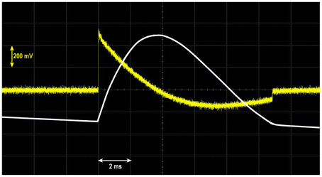
Figure 2. Snapshot of the digital oscilloscope displaying an output curve from the field-sensing coil (yellow), along with its integration with respect to time (white). The intensity of the maximum peak field is equivalent to 0.7 T. A slightly negative baseline trend of the integrated field is due to a small dc offset (<1 μV) of the oscilloscope.
Samples
To test the performance of the present system, we chose a set of synthetic and natural samples. An aluminum sample (Al), 10 mm square and 1 mm thick, was chosen to observe the effect of eddy current loss, which is increased by the application of a pulsed field. To maximize the eddy current effect, the sample was placed in the sample cavity with its plane normal to the pulsed field. A commercial permalloy ribbon sample (PL), 0.1 mm thick, 3 mm wide, and 40 mm long (TMC-V, Tohkin Co. Ltd.), was folded and twisted a couple of times, and placed into a 7-cc plastic cube to minimize the eddy current effect. This sample was chosen to examine how such a soft magnetic material will respond to a pulsed field. A nickel sample (Ni) was prepared from pure nickel powder (d < 75 μm, 99.9% purity) glued with epoxy in a plastic cube for the system calibration. The net weight of the powder was 5.8 g. Two volcanic rock samples (OS2-2 and OT73-4-3) were chosen as natural samples because of their relatively strong saturation magnetizations, ~1/10 those of the PL and Ni samples. According to measurements by a VSM, sample OS2-2 has a paramagnetic component recognizable over 1.8 T, whereas sample OT73-4-3 is saturated in a much lower field with a small paramagnetic fraction. We examined how the static field magnetic behaviors of these samples changed in pulsed fields.
Results
Synthetic Samples
Results from the synthetic samples showed dynamic magnetic behaviors in the plots of magnetization vs. time (M–t) and magnetization vs. field (M–H). The curves were remarkably different between samples (Figures 3–5).
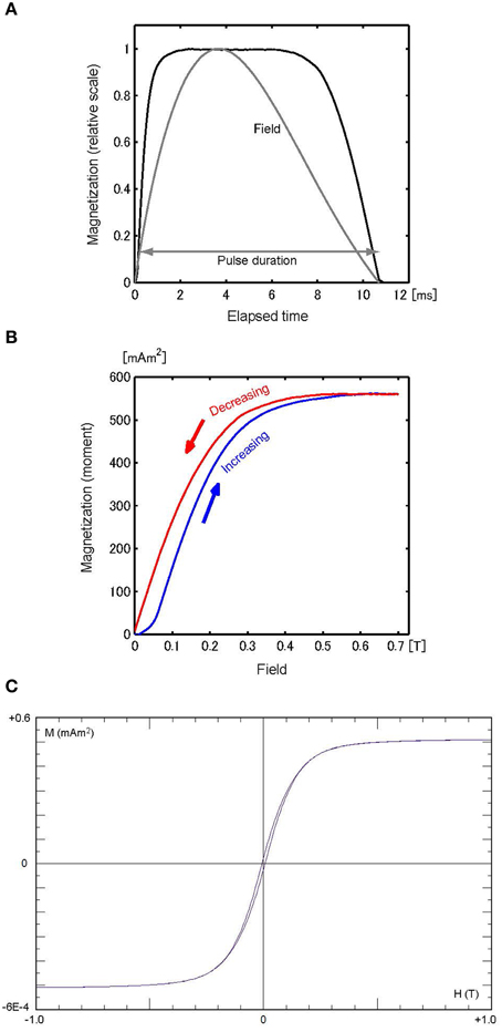
Figure 3. (A) M-t curve of sample Ni, scaled to the maximum magnetization (561 mAm2), with the H–t curve (gray) scaled to 0.7 T. (B) M–H curve for the increasing field (blue) and reducing field (red). (C) Hysteresis loop of Ni (10.7 mg).
The M–H curve for sample Ni (Figure 3B) is comparable to the hysteresis loop (Figure 3C) that is typical for ferromagnetic materials with moderate magnetic coercivity. Both the M–H curve and the hysteresis loop become saturated around H = 0.5 T. This agreement means that the Ni sample is immediately magnetized by a pulsed field. The M–t curve (Figure 3A) demonstrates rapid variation in magnetization, with a broad plateau that corresponds to the magnetic saturation. However, it is not accompanied by noticeable tail-off after the pulse. Calibration of the system in this study was accomplished by the correlation of the saturation magnetization of the hysteresis loop with the peak value in Figure 3B, resulting in 29.1 μ Am2/mVs. Using this correlation constant, the raw data were converted into magnetic moments in Figures 3–5. Measurements were made with different orientations of the sample to identify the demagnetization effect due to the sample shape, but no discernible difference was observed.
The M–t curve for the Al sample recovered rapidly from the initial fall, increased to a positive peak, and then decreased until the field was turned off (Figure 4A). Note that the positive peak occurs later than the field peak. This pattern can be observed in a different form in the M–H curve (Figure 4B). The initial steep fall in the M–t curve corresponds to the broader negative peak in the first half-cycle of the M–H curve, whereas the maximum in the M–t curve corresponds to the gradual peak in the restoring cycle. These behaviors with respect to time and the field can be qualitatively explained in terms of the eddy current effect. The eddy current is proportional to |−∂H/∂t|, so its effect is opposite depending on the sign of |−∂H/∂t|. Additionally, as shown in the asymmetrical H–t curve (Figure 4A), the magnitude of the time derivative |−∂H/∂t| is greater for the increasing phase than for the decreasing phase. Thus, the resulting eddy current effect was enhanced for the former compared with the latter. The M–H curve does not return to the origin, but intercepts the y-axis at about half the value of the maximum peak. This temporary magnetization at H = 0 decays rapidly, as shown in Figure 4A, indicating the halt of the eddy current and the presence of magnetic viscosity.
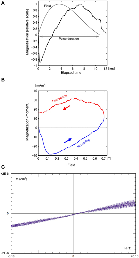
Figure 4. (A) M–t curve of sample Al, scaled to the maximum magnetization (32 mAm2). The H–t curve (gray), scaled to the peak value of 0.7 T, is provided for comparison. (B) M–H curve for the increasing field (blue) and reducing field (red). (C) VSM result of Al (26.7 mg).
To characterize the eddy current effect in a quantitative manner, we calculated the skin depth δ, the depth at which the current density is reduced to 1/e of its value at the surface. For a conductive material in an applied AC field with frequency f, δ = (ρ /π μf)1/2, where ρ is the resistivity and μ is the magnetic permeability. Assuming a pulse “frequency” f ~1/(2 × pulse-width) = 40 Hz, with ρ = 2.6 × 10⁻⁸ (Ω m) and μ = 2.26 × 10⁻⁶ (H/m) for aluminum, δ is ~13 mm, which is significantly greater than the sample thickness. This suggests that the pulse penetrates effectively into the sample, without substantial cancelation by the opposing field induced by the eddy current. However, this estimation is inaccurate because it approximates f using the entire pulse length. It is more appropriate to substitute f with |−∂H/∂t|, which varies with time, as shown in Figure 1. Note that the rapid fall in M occurs within a rise time of 0.3 ms for H when |−∂H/∂t| is still about 80% of the initial value. The rapid rise of |−∂H/∂t| suggests that it is made up of harmonics with orders of magnitude greater than 40 Hz; thus, it is likely that δ is especially small for this moment. For example, substituting f with 4 kHz leads to a δ value of 1 mm, which is comparable with the sample thickness. Consequently, the induced magnetic flux opposing the pulse becomes prominent. A more quantitative explanation of the eddy current effect is based on a model that takes into account the geometry and electromagnetic properties of the sample, as well as the shape and duration of the pulse. For this purpose, it is necessary to construct more sensitive instrumentation with the ability to change the shape and length of the pulse (e.g., Jewell et al., 1992; Ludwig et al., 2002), which will be described in a companion paper. In contrast to these dynamic magnetic behaviors, the VSM result in Figure 4C shows a linear M–H trend superimposed on high-frequency variations, with amplitude that tends to increase as the field increases. The linear trend can be interpreted as weak paramagnetism, whereas the high-frequency fluctuations, which were proportional to the static field, correspond to low magnetization induced by the eddy current resulting from the sample vibration.
Sample PL also demonstrated unique M–t and M–H patterns. The M–t curve in Figure 5A has a maximum peak, but it occurs later than the pulse peak. Immediately after the pulse was turned off, a large amount of magnetization decayed rapidly over a short period of time (~3 ms). The delayed peak of the M–t curve suggests that the sample temporarily became so viscous that it could not be magnetized synchronously with the pulse. Consequently, the M–H curve in Figure 5B acquired an irreversible shape that is considerably different from the hysteresis loop (Figure 5C). The M–H curve does not return to the origin, but the y-intercept is only slightly smaller than the maximum peak. These results are consistent with studies of soft ferromagnetic materials (e.g., Grössinger et al., 2004) showing that the magnetic viscosity is dependent on the field sweep rate.
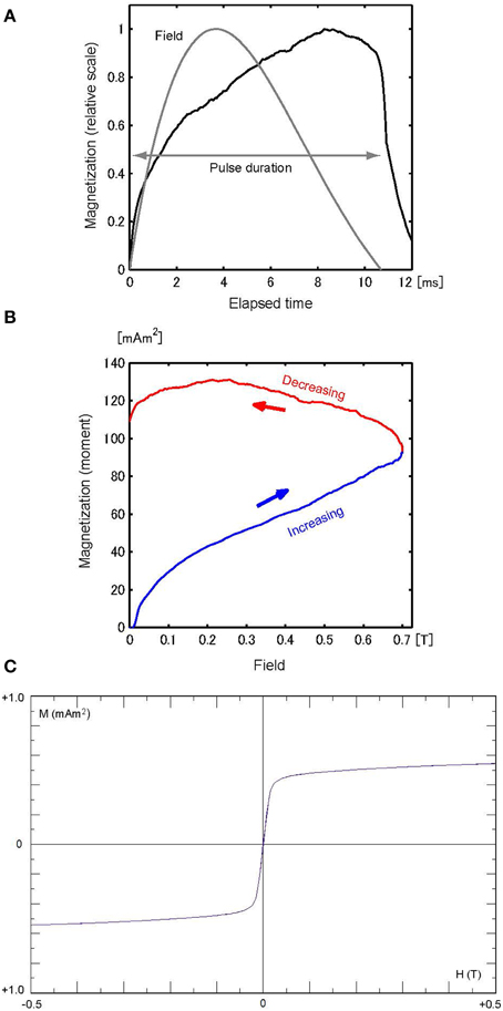
Figure 5. (A) M–t curve of sample PL, scaled to the maximum magnetization (131 mAm2), with the H-t curve (gray) scaled to 0.7 T. (B) M–H curve for the increasing field (blue) and reducing field (red). (C) Hysteresis loop of PL (5.5 mg).
Natural Samples
Results from the two volcanic rocks, OS2-2 and OT73-4-3, are shown in Figures 6, 7, respectively. Because their magnetizations were about one order of magnitude weaker than that of sample Ni, measurements were repeated 10 times for each sample. To demagnetize remanent magnetization, AC demagnetization with a peak field of 180 mT was carried out before each measurement. The results are provided in terms of a mean curve and error range (±1σ). The mean M–t curves (Figures 6B, 7B) show that the error range is smaller on each side of the pulse than for the remainder of the curve. This is principally due to the fact that the output of the sensing coil is proportional to the time derivative of the magnetic flux, which is dominated by |−∂H/∂t|, and |−∂H/∂t| is smaller and the SNR is reduced around the pulse peak. Additionally, the individual M–t curves (Figures 6A, 7A) do not tend to shift toward an equilibrium state in a manner referred to as accommodation, a gradual drift to an equilibrium loop that has often been observed for the cycled measurements of minor hysteresis loops (e.g., Della Torre, 1999). The absence of this kind of drift suggests that the mean M–t curves can be considered as statistical means of repeated measurements.
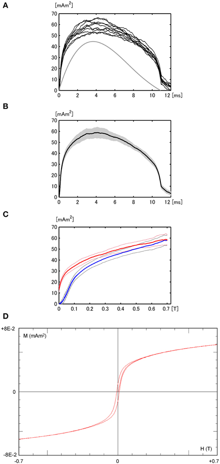
Figure 6. (A) M–t curves from measurements repeated 10 times for sample OS2-2. The H-t curve (gray, not to scale) is provided for comparison. (B) Mean M–t curve and the error range (gray). (C) Mean M–H curve and associated error range for the increasing field (blue) and reducing field (red). (D) Hysteresis loop of OS2-2 (30.5 mg) including magnetization after initial demagnetization.
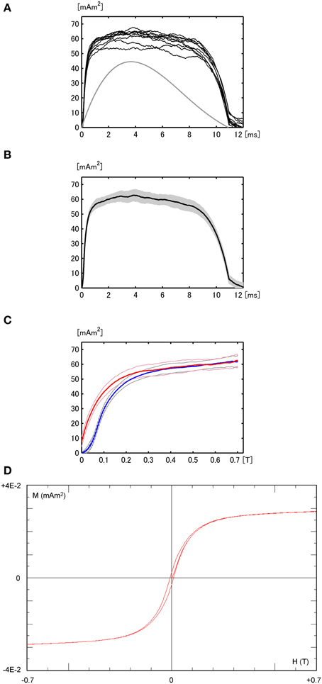
Figure 7. (A) M–t curves from measurements repeated 10 times for sample OT73-4-3, with the H-t curve (gray, not to scale). (B) Mean M–t curve and the error range (gray). (C) Mean M–H curve and associated error range for the increasing field (blue) and reducing field (red). (D) Hysteresis loop of OT73-4-3 (18.5 mg) including magnetization after initial demagnetization.
The mean M–H curves in Figures 6C, 7C are generally consistent with the respective VSM results in Figures 6D, 7D. There is a slight difference in the increasing rate near H = 0, which is smaller for the M–H curve than for the VSM result. This discrepancy can be phenomenologically explained by the difference in the time scale of the magnetization processes under consideration. That is, in the case of the pulsed field, a fraction of the magnetic particles with a relaxation time longer than the pulse rise rate fail to follow the pulse. This is not the case for the VSM because the field sweep rate is about four orders of magnitude slower than the pulsed field, so most of the magnetic particles can be magnetized simultaneously with the applied field.
Discussion
The similarities between the M–H curves and the VSM results for the natural samples suggest that the method described in this paper can serve as an alternative. The pulse magnetometry has some advantages over the VSM measurement: the sample size can be standardized to a 1” cylinder, a cube of equivalent size, or any size that can be accommodated in the sample cavity of a pulse magnetizer. Hence, bulk magnetic properties can be obtained without preparing small amounts of samples, especially for a VSM. This can help ensure sample homogeneity. Furthermore, the time required for one measurement is less than 1 min. In practice, most of the time is spent charging the capacitor to a specified voltage level, which usually takes a few tens of seconds for the pulse magnetizer employed in this study. We will describe additional features, advantages, or limitations of the present system before considering its application to rock magnetic investigations.
Note that the sensitivity of the present system is rather low compared with that of conventional instruments, such as the VSM. This issue can be resolved to some extent by repeated measurements, as demonstrated in this study. In practice, it is not feasible to repeat measurements many times due to the possible temperature rise in the pulse coil, which results in increased thermal drift. Thus, to achieve a SNR that is large enough for measuring weakly magnetic samples, such as sediments and soils, one practical solution may be to shorten the pulse duration; the sensitivity of the inductive sensing coils is proportional to the time derivative of the pulse. A larger SNR can be realized by replacing the pulse coil or the capacitor with one that has lower inductance or capacitance, but this requires intricate modifications of the pulse magnetizer. It is expected that an analog amplification circuit using high-speed, high-precision operational amplifiers could improve the sensitivity. However, the advantage of using an additional circuit might be limited, because it may increase the electronic noise of the output, with little improvement to the SNR. Instead, a more effective measure may be the repeated application of ultra-fast pulses using a high-power pulse generator and sophisticated digital processing techniques.
One might assume that a larger number of turns in pick-up coils would result in higher sensitivity. To test this assumption, we experimented with different coil configurations. The assumption, however, proved false for the system in this study, principally due to the stray capacitance of coils (Cs) that arises with an increasing number of coil turns. Coupled with coil impedance (L), this may result in resonance with a frequency Fs = 2π /(LCs)1/2 when the applied field contains higher harmonics with the same frequency as Fs. This was the case in the present system, because, as shown in Figure 2, the pulse has an asymmetrical wave form, with a rise time shorter than the fall time. This means that the frequency spectrum of the pulse is widespread, including a component with Fs. It is thus expected that this high harmonic component could excite the LCs resonant system. This kind of phenomena was observed in practice. For example, in the case of a 0.7-T pulse, large-amplitude (~1 V) and high-frequency oscillations were observed in the coil output, but only within a very short period of time (<0.2 ms from the start of the pulse). Integration of the output and a low-pass filter greatly reduced those resonant wave components to ~0.3 mVs, which is four orders of magnitude smaller than the signals of the natural samples. Thus, it is concluded that the stray capacity of the pick-up coil does not affect the shape of the M–t and M–H curves, as long as the pulse is <1 T. However, pulsed fields above 1 T intensified the resonant oscillations of amplitude >2 V, resulting in a significantly lower SNR. These are the reasons why we used a 0.7-T pulse in this study.
The present system cannot draw closed hysteresis loops, such as those obtained by a VSM. Studies in high-magnetic-field physics (e.g., Nojiri et al., 2007; Grössinger, 2008; Takeyama et al., 2012) have used laboratory-made pulse magnetizers capable of producing one cycle of pulsed fields, allowing the measurement of one closed M–H loop. However, even the open M–H curves shown in Figures 6, 7 can provide information that could serve rock magnetic investigations. For example, let us assume that the magnetization of a sample at the end of a pulse is M(Δt), where Δt is the pulse duration, and that the sample has a characteristic magnetic relaxation time τs < Δt. Then, it is expected that, immediately after the pulse, M(Δt) will decay exponentially with the time constant τs toward magnetization in equilibrium. Therefore, the M–H curve in the reducing field phase does not directly correspond to the portion of a hysteresis loop that returns from positive saturation. This leads to the inference that the M(Δt)/Msp ratio, where Msp is the saturation magnetization induced by a pulse, will be greater than the remanence ratio Mrs/Ms, where Mrs and Ms are the saturation remanent magnetization and the saturation magnetization, respectively, measured with a quasi-static instrument such as a VSM. These parameters were calculated for the two natural samples. The results were as follows: M(Δt)/Msp = 0.12 ± 0.05, Mrs/Ms = 0.091 ± 0.003 for sample OT73-4-3 and M(Δt)/Msp = 0.295 ± 0.065, Mrs/Ms = 0.185 ± 0.004 for sample OS2-2. Thus, M(Δt)/Msp for sample OS2-2 was about 60% greater than Mrs/Ms, a statistically significant difference. For sample OT73-4-3, despite the large error, M(Δt)/Msp was about 30% greater than Mrs/Ms. The large error for OT73-4-3 reflects the low SNR due to the fact that M(Δt) was about 50% smaller than that of sample OS2-2.
Figures 8A,B show the M–t curves for the three samples (OS2-2, OT73-4-3, and PL), with a focus on to the short interval (3 ms) after the termination of the pulse in Figure 5A (PL), Figure 6B (OS2-2), and Figure 7B (OT73-4-3). The y-intercept in each figure corresponds to M(Δt). The exponential decay of these curves allows for estimation of the decay constant τ. The τs are 0.96 ± 0.04 ms for OS2-2 and 0.87 ± 0.04 ms for OT73-4-3, whereas sample PL has a value ~15% smaller, 0.78 ± 0.03 ms. Because sample PL is a permalloy whose magnetization processes are expected to be dominated by the displacement of domain walls (DWs), the curve in Figure 8B can be understood as magnetic relaxation, indicating that the DWs moved after the field was turned off. In the same way, it is assumed that the curves in Figure 8A could represent magnetic relaxations for which the dynamics of DWs is responsible. Furthermore, the fact that these three samples are of different origin but had similar relaxation decay constants (τ) is an indication that the underlying magnetization mechanism is common among them.
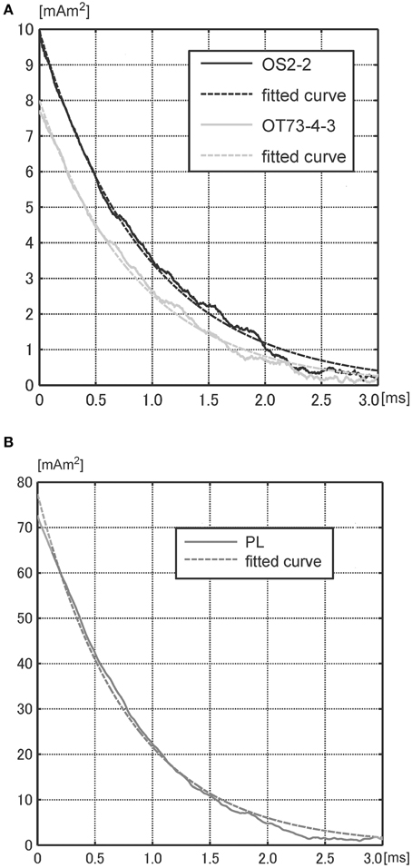
Figure 8. Mean M–t curves (solid) and fitted exponential curves (dotted), focusing on to the short interval (3 ms) after turning off a pulsed field. (A) sample OS2-2 and OT73-4-3. (B) sample PL.
In terms of frequency, the estimated τ corresponded to frequencies on the order of 103 Hz. The frequencies were orders of magnitude lower than those of the reversible oscillations of DW reported for synthetic nanomaterials, which were on the order of 105 Hz or higher (Ganpule et al., 2001; Prida et al., 2003; Buttino et al., 2004; Valenzuela et al., 2005). Hence, these low frequencies could be interpreted in terms of an irreversible displacement of DWs that must overwhelm energy barriers due to DW pinning, lattice defects, internal stress, and so forth, generally yielding characteristic frequencies that are typically two orders of magnitude lower than the reversible motion of DWs (Betancourt, 2010). To better understand these temporal magnetization processes in terms of DW dynamics, it will be necessary to conduct combined analyses in the frequency domain, including measurements of AC susceptibilities over a wide range of frequencies (e.g., Kodama, 2013), analyses of the dispersion of complex susceptibilities (Valenzuela, 2001; Chen et al., 2002; Zhou et al., 2010), and investigations of the frequency dependence of hysteresis loops (Lobue et al., 2000; Lente et al., 2004; Yang et al., 2010).
Conclusion
Dynamic magnetization processes caused by the application of a pulsed field can be measured using laboratory-made instrumentation comprising an inductive sensing coil system combined with a high-speed digital oscilloscope. This system allows the reconstruction of the magnetization–time and –field curves within less than 1 min for one sample. Results from synthetic and natural samples suggest that the M–H curves may be useful for assessing the characteristics of the hysteresis loop without using a VSM. The proposed system can also measure the rapid decay of magnetization after the pulsed field is turned off. This short aftereffect can be interpreted as magnetic relaxation, which could be accounted for by the dynamics of DWs. These results suggest that the proposed method, combined with measurements in the frequency domain, will serve as a new characterization tool that is sensitive to a variety of intrinsic magnetic properties of natural materials.
Conflict of Interest Statement
The author declares that the research was conducted in the absence of any commercial or financial relationships that could be construed as a potential conflict of interest.
Acknowledgments
The author is grateful to T. Nishioka for valuable comments and Y. Yamamoto for providing volcanic rock samples. Financial support from the Monbusho Kakenhi No. 24540455 is acknowledged. This is contribution PMG15–01 from the Centre for Advanced Marine Core Research, Kochi University.
References
Abrajevitch, A., and Kodama, K. (2011). Diagenetic sensitivity of paleoenvironmental proxies: a rock magnetic study of Australian continental margin sediments. Geochemistry Geophys. Geosystems 12, 1–18. doi: 10.1029/2010GC003481
Betancourt, I. (2010). Magnetization dynamics of amorphous ribbons and wires studied by inductance spectroscopy. Materials (Basel). 4, 37–54. doi: 10.3390/ma4010037
Buttino, G., Cecchetti, A., and Poppi, M. (2004). Domain wall relaxation frequency and magnetocrystalline anisotropy in Co–and Fe-based nanostructured alloys. J. Magn. Magn. Mater. 269, 70–77. doi: 10.1016/S0304-8853(03)00563-8
Chen, X., Sichelschmidt, O., Kleemann, W., Petracic, O., Binek, C., Sousa, J., et al. (2002). Domain wall relaxation, creep, sliding, and switching in superferromagnetic discontinuous Co80Fe20/Al_2O_3 Multilayers. Phys. Rev. Lett. 89, 137–203. doi: 10.1103/PhysRevLett.89.137203
Pubmed Abstract | Pubmed Full Text | CrossRef Full Text | Google Scholar
Dudding, J., Cornelius, R., Knell, P., Lin, A., and Jian, H. (2006). Improved repeatability of pulsed field magnetometry measurements through Peltier effect temperature control of measurement coils. J. Iron Steel Res. Int. 13, 388–392. doi: 10.1016/S1006-706X(08)60215-0
Dudding, J., Knell, P. A. A., Cornelius, R. N. N. N., Enzberg-Mahlke, B., Fernengel, W., Grössinger, R., et al. (2002). A pulsed field magnetometer for the quality control of permanent magnets. J. Magn. Magn. Mater. 242, 1402–1404. doi: 10.1016/S0304-8853(01)01247-1
Egli, R. (2003). Analysis of the field dependence of remanent magnetization curves. J. Geophys. Res. 108, 2081. doi: 10.1029/2002JB002023
Egli, R. (2004). Characterization of individual rock magnetic components by analysis of remanence curves. 2. Fundamental properties of coercivity distributions. Phys. Chem. Earth 29, 851–867. doi: 10.1016/S1474-7065(04)00129-9
Ganpule, C., Roytburd, A., Nagarajan, V., Hill, B., Ogale, S., Williams, E., et al. (2001). Polarization relaxation kinetics and 180° domain wall dynamics in ferroelectric thin films. Phys. Rev. B 65:14101. doi: 10.1103/PhysRevB.65.014101
Grössinger, R. (2008). Characterisation of hard magnetic materials. J. Electrical Engineering 59, 15–20.
Grössinger, R., Jewell, G. W., Dudding, J., and Howe, D. (1993). Pulsed field magnetometry. IEEE Trans. Magn. 29, 2980–2982. doi: 10.1109/20.280897
Grössinger, R., Turtelli, R. S., and Téllez-Blanco, C. (2004). The influence of the magnetic viscosity on pulsed field measurements. J. Optoelectron. Adv. Mater. 6, 557–563.
Heslop, D., Dekkers, M. J., Kruiver, P. P., and Van Oorschot, I. H. M. (2002). Analysis of isothermal remanent magnetization acquisition curves using the expectation-maximization algorithm. Geophys. J. Int. 148, 58–64. doi: 10.1046/j.0956-540x.2001.01558.x
Jewell, G. W., Howe, D., Schotzko, C., and Grössinger, R. (1992). A method for assessing eddy current effects in pulsed magnetometry. IEEE Trans. Magn. 28, 3114–3116. doi: 10.1109/20.179730
Kapitza, P. L. (1924). A method of producing strong magnetic fields. Proc. R. Soc. A Math. Phys. Eng. Sci. 105, 691–710. doi: 10.1098/rspa.1924.0048
Kodama, K. (2013). Application of broadband alternating current magnetic susceptibility to the characterization of magnetic nanoparticles in natural materials. J. Geophys. Res. 118, 1–12. doi: 10.1029/2012JB009502
Kruiver, P. P., Dekkers, M. J., and Heslop, D. (2001). Quantification of magnetic coercivity components by the analysis of acquisition curves of isothermal remanent magnetisation. Earth Planet. Sci. Lett. 189, 269–276.
Lente, M. H., Picinin, A., Rino, J. P., and Eiras, J. A. (2004). 90°domain wall relaxation and frequency dependence of the coercive field in the ferroelectric switching process. J. Appl. Phys. 95, 2646–2653. doi: 10.1063/1.1645980
Lobue, M., Basso, V., Tiberto, P., Beatrice, C., and Bertotti, G. (2000). Hysteresis and thermal relaxation in nanocrystalline soft magnetic materials. J. Magn. Magn. Mater. 216, 446–448. doi: 10.1016/S0304-8853(00)00185-2
Ludwig, R., Bretchko, P., and Makarov, S. (2002). Magnetic and eddy current effects in an open-loop pulsed hysteresis graph system for magnetization of rare-earth magnets. IEEE Trans. Magn. 38, 211–220. doi: 10.1109/20.990110
Miura, N. (2007). “Experimental techniques for high magnetic fields,” in Physics of Semiconductors in High Magnetic Fields, Series on Semiconductor Science and Technology 15, eds R. Nicholas, R. Williams, and H. Kamimura. (New York, NY: Oxford University Press), 299–325.
Nojiri, H., Choi, K.-Y., and Kitamura, N. (2007). Manipulation of the quantum tunneling of nanomagnets by using time-dependent high magnetic fields. J. Magn. Magn. Mater. 310, 1468–1472. doi: 10.1016/j.jmmm.2006.10.616
Prida, V. M. M., Sánchez, M. L., Hernando, B., Gorria, P., Tejedor, M., Vázquez, M., et al. (2003). Influence of stress relief on hysteretic magnetoimpedance in Co-rich amorphous ribbons at the relaxation frequency. Appl. Phys. A Mater. Sci. Process. 77, 135–140. doi: 10.1007/s00339-002-2030-3
Prieto Astalan, A., Jonasson, C., Petersson, K., Blomgren, J., Ilver, D., Krozer, A., et al. (2007). Magnetic response of thermally blocked magnetic nanoparticles in a pulsed magnetic field. J. Magn. Magn. Mater. 311, 166–170. doi: 10.1016/j.jmmm.2006.10.1182
Takeyama, S., Sakakura, R., Matsuda, Y. M., Miyata, A., and Tokunaga, M. (2012). Precise magnetization measurements by parallel self-compensated induction coils in a vertical single-turn coil up to 103 T. J. Phys. Soc. Jpn. 81, 1–7. doi: 10.1143/JPSJ.81.014702
Valenzuela, R. (2001). Low-frequency magnetoimpedance: domain wall magnetization processes. Phys. B 299, 280–285. doi: 10.1016/S0921-4526(01)00479-3
Valenzuela, R., Montiel, H., Gutiérrez, M. P. P., and Betancourt, I. (2005). Characterization of soft ferromagnetic materials by inductance spectroscopy and magnetoimpedance. J. Magn. Magn. Mater. 294, 239–244. doi: 10.1016/j.jmmm.2005.03.040
Yang, S. M., Jo, J. Y., Kim, T. H., Yoon, J.-G., Song, T. K., Lee, H. N., et al. (2010). ac Dynamics of ferroelectric domains from an investigation of the frequency dependence of hysteresis loops. Phys. Rev. B 82:174125. doi: 10.1103/PhysRevB.82.174125
Keywords: pulsed field, instrumentation, magnetic relaxation, dynamic magnetization, hysteresis
Citation: Kodama K (2015) Measurement of dynamic magnetization induced by a pulsed field: Proposal for a new rock magnetism method. Front. Earth Sci. 3:5. doi: 10.3389/feart.2015.00005
Received: 01 December 2014; Accepted: 30 January 2015;
Published online: 17 February 2015.
Edited by:
Joshua M. Feinberg, University of Minnesota, USAReviewed by:
Oscar Pueyo Anchuela, Universidad de Zaragoza, SpainRamon Egli, Central Institute for Meteorology and Geodynamics, Austria
Copyright © 2015 Kodama. This is an open-access article distributed under the terms of the Creative Commons Attribution License (CC BY). The use, distribution or reproduction in other forums is permitted, provided the original author(s) or licensor are credited and that the original publication in this journal is cited, in accordance with accepted academic practice. No use, distribution or reproduction is permitted which does not comply with these terms.
*Correspondence: Kazuto Kodama, Center for Advanced Marine Core Research, Kochi University, Monobe B-200, Nankoku, Kochi 783−8502, Japan e-mail:a2RtYUBrb2NoaS11LmFjLmpw
 Kazuto Kodama