- 1Human Robotics Lab, Information Science and Engineering, Graduate School of Science and Technology, Nara Institute of Science and Technology, Ikoma, Japan
- 2Sakagami Lab, Navigation and Ocean Engineering, School of Marine Science and Technology, Tokai University, Shimizu, Japan
In recent years, significant attention has been paid to remotely operated underwater vehicles (ROVs) in the performance of underwater tasks, such as the inspection and maintenance of the underwater infrastructure. The workload of ROV operators tends to be high, even for the skilled operators. Therefore, assistance methods for the operators are desired. This study focuses on a task in which a human operator controls an underwater robot to follow a certain path while visually inspecting objects in the vicinity of the path. In such a task, it is desirable to achieve the speed of trajectory control manually because the visual inspection is performed by a human operator. However, to allocate resources to visual inspection, it is desirable to minimize the workload on the path-following by assisting with the automatic control. Therefore, the objective of this study is to develop a cooperative path-following control method that achieves the above-mentioned task by expanding a robust path-following control law of non-holonomic wheeled vehicles. To simplify this problem, we considered a path-following and visual objects recognition task in a two-dimensional plane. We conducted an experiment with participants (n = 16) who completed the task using the proposed method and manual control. We compared results in terms of object recognition success rate, tracking error, completion time, attention distribution, and workload. The results showed that both the path-following errors and workload of the participants were significantly smaller with the proposed method than with manual control. In addition, subjective responses demonstrated that operator attention tended to be allocated to object recognition rather than robot operation tasks with the proposed method. These results demonstrate the effectiveness of the proposed cooperative path-following control method.
1 Introduction
Unmanned underwater vehicles (UUVs) have attracted significant attention owing to the rapid increase in the demand for underwater tasks (Shimono et al., 2016). UUVs are classified into autonomous underwater vehicles (AUVs) and remotely operated vehicles (ROVs). AUVs are controlled using all the sensor information acquired by the underwater robot. AUVs can be operated for a long time and are often used for topographic surveys and water quality testing (Jimin et al., 2019). However, AUVs have some limitations (Li and Du, 2021), such as the need for preparing in advance a specific environment (Balasuriya et al., 1997) and the difficulty in performing complex movements (Vaganay et al., 2006). Therefore, it is problematic to rely solely on autonomous control by the system because it is currently limited to specific cases and cannot navigate unexpected situations, such as disturbances. Therefore, human operators are required to frequently participate in some complex underwater tasks (Choi et al., 2017; Amundsen et al., 2022), such as the inspection and maintenance of underwater infrastructure. Therefore, human-controlled ROVs are widely used for such tasks.
In this study, we focused on underwater inspection along a certain trajectory or path using ROVs. It has been observed that operation training is indispensable for ROV operators to achieve satisfactory performance because advanced skill is required. For example, the operator is required to operate the ROV based on a limited source of information, such as video images having a small field of view from a camera attached to the ROVs and/or poor perception of the position and orientation of the robot. The workload of the operators also tends to be high even for the skilled operators (Ho et al., 2011; Azis et al., 2012; Christ and Wernli, 2014). Therefore, assistance methods for the ROV operators have been desired for improving the work efficiency, decreasing the workload, and prolonging the workable time of the operator.
Cooperative control, which is a combination of automatic and human manual control, is a promising approach to assist human operators in a variety of remotely operated or other types of human–machine systems (Flemisch et al., 2016; Wada, 2019) because it incorporates advanced technologies of autonomous control and/or other machine intelligence with manual control. Shared control is one of the cooperative control systems in which humans and machines interact congruently in a perception-action cycle to jointly perform a dynamic task (Mulder et al., 2012). Haptic shared control (HSC) is a branch of shared control in which control inputs of both humans and a machine are forced or torqued to a single control terminal, and the human operator perceives the input of the machine through the haptic-information sensation generated by the terminal (Abbink et al., 2012; Nishimura et al., 2015). HSCs have been introduced in a wide range of fields of human–machine cooperation, such as the automotive field to assist drivers (Benloucif et al., 2019), telemanipulation in space (Stefan et al., 2015), underwater robots (Kuiper et al., 2013; Konishi et al., 2020), and aircraft control (Lam et al., 2007). All the above studies suggest that human–machine interaction improves overall system performance. Cooperative control methods are designed according to the content of a given task, in which different cooperative schemes are combined in some cases.
The present study focuses on a task in which a human operator remotely controls an underwater robot to follow a certain path while visually inspecting objects in the vicinity of the path. Such a task is found in underwater missions, such as pipe inspection (Kim et al., 2020). In this task, it is desirable to manually achieve the speed of trajectory control because visual inspection is performed by a human. To allocate resources to visual inspection, it is desirable to minimize the workload on the task of path following by assisting with the autonomous control. Therefore, the purpose of this study is to develop a cooperative path-following control method for ROVs suitable for human visual inspection to improve the path-following performance of the overall system and reduce the workload of the operator who simultaneously conducts visual inspection and path-following by remotely operating the robot. Specifically, we extend the path-following control of non-holonomic wheeled vehicles based on the inverse optimal control law (Kurashiki et al., 2008) to holonomic underwater robots and propose a new cooperative path-following control method suitable for human visual inspection tasks by combining the path-following controller and operator guidance methods.
In the proposed method, HSC is applied to guide the direction of the heading angle control of the robot. For translational motion, the direction of the vehicle movement is automatically tuned according to the magnitude of the lateral deviation from the target path to further assist the path-following activity of the operator, and the speed of the translational motion is determined by the input of the operator. The proposed method was implemented on an underwater robot, and experiments, in which participants performed an object recognition task during path following, were conducted to investigate the effectiveness of the proposed method.
This paper is organized as follows: Section 2 describes the design concept and the details of the proposed method. Section 3 describes the experimental method. In Section 4, the results of the subjective experiment are presented. Section 5 discusses the obtained results. Finally, conclusions are presented in Section 6.
2 Proposed method
2.1 Design of cooperative control
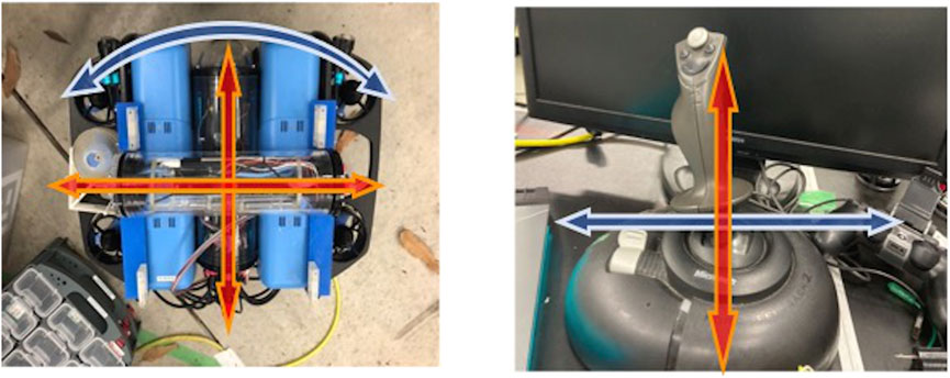
When the underwater robot moves in a two-dimensional plane, the motion of the robot with three degrees of freedom (DoF), as shown in the left part of Figure 1, must be specified. However, the operation of all three-DoF movements is expected to be difficult for novice operators to master. Therefore, it is considered that the three-DoF movement is reduced to a two-DoF movement such that the operator can operate more intuitively with a lower workload. Among several methods to degenerate dimensions, the most commonly used method is to assign the tilt and roll angles of the joystick to the translational and rotating motions of the underwater robot, respectively (Figure 1). When an underwater robot is used for the recognition of objects or visual inspection while following a path, it is important to not change the robot orientation significantly. Thus, the dimension for the orientation controls is assigned to the independent joystick motion.
The proposed assistance method provides two different guidance methods for the translational and rotational motions of the underwater robot, which are described in the following section:
(1) Translational velocity conversion: It is the first guidance method employed to automatically determine the direction of the translational motion of the underwater robot, as indicated by the red arrow in Figure 3. Normally, without the assistance of the system, the robot is operated to longitudinal speed by the joystick tilt angle, and to the robot turning speed by roll angle, as described below in Section 3.2. As shown in Figure 2, in translational velocity conversion, the operator determines only the magnitude of the translational velocity of the underwater robot by operating the joystick to adjust the tilt angle. The system determines its direction according to the distance to the path, as shown in Figure 3. This guidance method cannot be interfered with by the operator only by the joystick tilt angle while the operator can resist this guidance by changing the orientation of the robot using the joystick roll angle.
(2) Haptic guidance: In the second guidance method, the HSC indicates how the operator should operate the joystick to correct the posture of the underwater robot. As indicated by the blue arrow in Figure 3, in the proposed method, a system and a human cooperate through a joystick. This guidance provides the operator with haptic information on how to operate the joystick roll angle to achieve the target angular velocity of the underwater robot using the control law described in Section 2.2. This guidance is mainly beneficial for following a curved path or maintaining the posture to align the direction of the path to stabilize the video image observed by the operator for visual inspection. The operator can ignore or defy the haptic guidance to operate the underwater robot as the operator desires. The operator is allowed to defy the guidance because the operator can overcome a situation corresponding incomplete recognition of the desired path by responding flexibly.
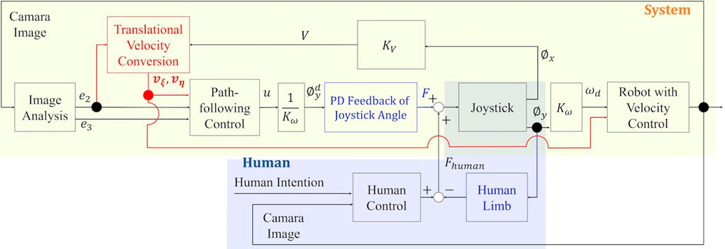
FIGURE 3. Block diagram of the proposed method used for an underwater robot. e2, e3: The lateral and angular errors between the virtual reference and real robots. u: The calculated input angular velocity.
2.2 Theory of cooperative path-following control for holonomic underwater robots
2.2.1 Translational velocity conversion
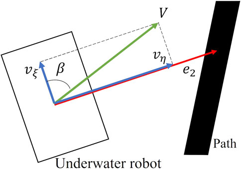
In this system, three variables of the longitudinal velocity vξ, lateral velocity vη and angular velocity ω of the underwater robot can be considered as inputs at the present stage. To achieve cooperative control with humans, we consider degenerating the input from three to two dimensions. In the context of this study, we assume that it is important to allow the operator determine the speed of path-following and achieve the process of path-following in a manner that does not change the orientation of the robot to avoid interfering with human visual inspection as much as possible. To achieve this, we propose the translational velocity conversion. In this method, the magnitude of the translation velocity V of the underwater robot is determined by the lever input in the tilt direction of the operator, and β, which is the direction of V as shown in Figure 4, is determined by the lateral error e2, as shown in Eqs 1, 2.
where vξ and vη are the longitudinal velocity and the lateral velocity of the real robot, respectively (Figure 5).
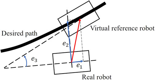
FIGURE 5. Definition of the Path-following error model (Kurashiki et al., 2008).
2.2.2 Haptic shared control for operating guidance
The second guidance method, haptic guidance, informs the operator through the haptic sensation how the underwater robot should be turned by the HSC. The blue arrow in Figure 3 depicts the feedback of the designed HSC.
Fukao (2004) proposed a trajectory control method of a non-holonomic vehicle using inverse optimal control (Sontag, 1983). Araki et al. (2017) and Kurashiki et al. (2008) expanded this method by Fukao (2004) to the path-following problem. In the present study, we propose a new cooperative path-following control method for a holonomic vehicle suitable for human cooperation based on Araki et al. (2017) and Kurashiki et al. (2008). The first guidance method, translational velocity conversion, is incorporated into the control law, and the second guidance method, optimal angular velocity of the robot for HSC, is derived.
As shown in Figure 5, we consider a reference robot moving on a desired path and design a control input that reduces the error between the real and reference robots. Although there is a delay between the input to the thrusters and the velocity of the underwater robot owing to the complexity of the system dynamics, we derive the dynamics of the controlled plant, in which the translational and angular velocities of the robot in the robot-fixed coordinate system are considered as the input by assuming the robot motion in the low-velocity range.
The position and orientation of the real robot in the world coordinate system
where vξ, vη, and ω denote the longitudinal, lateral, and angular velocities of the robot, respectively.
The position error between the real robot (i.e., [x, y, θ]) and virtual reference robot (i.e., [xr, yr, θr]), which has the same dynamics as the real robot, as shown in Figure 5, satisfies the following equation:
Differentiating Eq. 4 with respect to time yields the following equation:
Where vξr, vηr, and ωr denote the longitudinal, lateral, and angular velocities of the virtual reference robot, respectively, and the condition vηr = 0 is applied. Then, considering the translational velocity conversion, substituting Eq. 1 into Eq. 5 and rewriting Vr = vξr, we obtain Eq. 6 as follows:
In the case of path following, the longitudinal speed of the real robot is arbitrary, and the virtual reference robot is always designed in the y-axis direction of the real robot. Thus, the longitudinal error is always e1 = 0; therefore, de1/dt = 0. The Vr that satisfies this relationship is given by
The angular velocity of the virtual reference robot ωr is determined by ωr = ρVr, where ρ denotes the curvature of the path at the point where the virtual reference robot is located.
According to the above discussion, the error dynamics of the controlled plant can be expressed by an input-affine system, as referenced in Eq. 6, with state variables
Where
The inverse optimal control (Kurashiki et al., 2008) is designed for Eq. 8. We consider the following positive definite function:
where, c0 is a constant and,
It should be noted that the controller can be temporarily turned off by setting the errors (e2, e3) to zero when the system determines that it does not recognize the path to be followed for any reason. In such a case, β in Eq. 1 and u in Eq. 11 are zero, and the assistance by the system does not work. In addition, the operator allows the assistance to be turned off by pushing a button when the operator recognizes that the system is silent in failure.
The following equations convert the joystick tilt angle ϕx and roll angle ϕy to speed V and angular velocity ωd of an underwater robot, respectively:
Using the relationship in Eq. 16, the joystick target roll angle
The haptic controller provides PD feedback control for the joystick roll angle. Here, the output voltage to the motor attached to the joystick is determined as
In this study, the gain Kp, Kd, which determines the magnitude of the haptic feedback, is set such that it can be easily reversed by the operator; hence, the robot rotates to the ideal posture even if the operator does not apply any force to change the joystick roll angle.
3 Experiment
The proposed method would achieve tracking performance improvement in terms of tracking accuracy and required time, as well as workload reduction.
3.1 Scenario
In this study, we considered the case of the recognition of some objects while following a path.
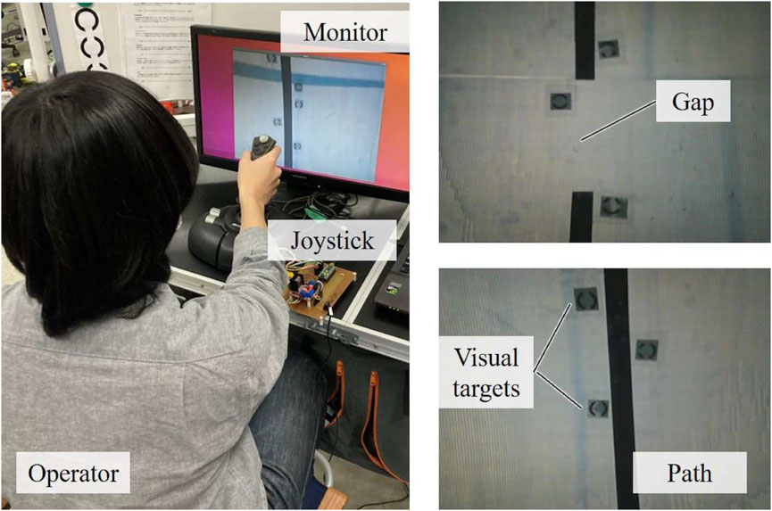
The objects depicted in Figure 6 were placed on the water surface with a path to be followed, and several visual targets were placed around the path for the recognition task of the objects. The tracking error from the path was calculated using the images obtained from the camera attached to the top of the underwater robot. To reproduce the situation, where it is difficult for AUVs to follow the path, the path is cut off at three points, which is depicted by Gaps A–C in Figure 6A. For simplicity, we attached an Augmented Reality marker at the start and end of each curve to determine the path curvature. As shown in Figure 6A, the path starts from the bottom-right corner, continues straight to the right, and then goes straight again after the two curves. Because the control in the horizontal plane was the main target in the present study, motion in the roll-pitch direction and depth were controlled to maintain the initial values by the inertial measurement unit and depth gauge built into the underwater robot.
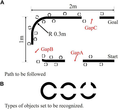
FIGURE 6. Path and objects used in the experiments. (A) Path to be followed (B) Objects to be recognized.
3.2 Design
The control method was treated as a within-subject factor, and manual control (MC) without the assistance of the system was prepared as a comparison target for cooperative control (CC) using the proposed method. In the MC condition, the underwater robot was moved forward and backward by varying the tilt angle of the joystick and turned by varying the roll angle, as follows:
In MC, because there is no assistance, the translational angle β shown in Figure 4 is zero, that is, the lateral velocity is zero. In both MC and CC, the maximum joystick tilt angle was 25 [deg] and the maximum roll angle was 20 [deg]. The HSC maximum torque in the CC was approximately 0.6 [N⋅ m].
3.3 Underwater robot
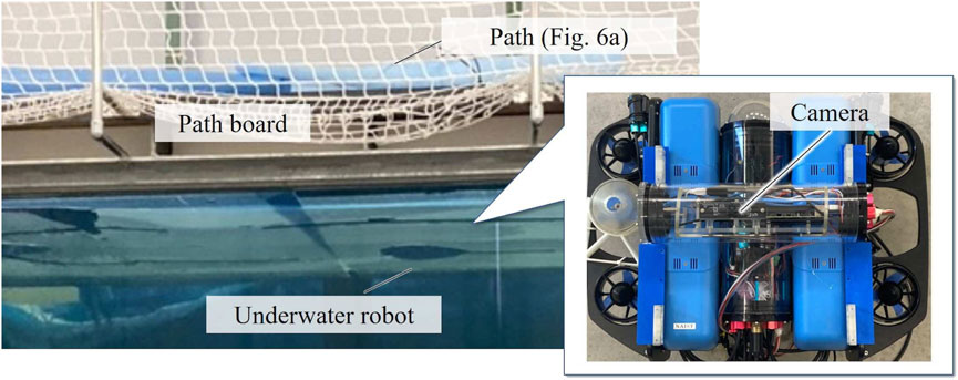
The proposed method was implemented on an underwater vehicle, as shown in Figure 7, with an upward facing camera attached to a BlueROV2 Heavy (Blue Robotics Inc.). A path-following experiment was conducted in an indoor pool (W5.4×D2.7×H1.6 m) at Nara Institute of Science and Technology, Japan. The underwater robot was equipped with four thrusters for the vertical motion and roll–pitch, and four thrusters for motion in the horizontal plane and yaw. The gains and coefficients used in this study are presented in Table 1. The gains and coefficients were determined empirically to the extent that the camera image of the underwater robot was stable and could feel the joystick movement and it also could be inverted.
In addition, Figure 8 shows that the lateral error e2 was obtained from the image as a pixel value. Therefore, it was converted to a meter value using Eq. 20, so that it could be applied to inverse optimal control. In this experiment, the underwater robot was assumed to move only in the horizontal plane and to have a fixed depth; hence, it can be linearly transformed to meter value as
3.4 Participants
Sixteen participants (13 males and 3 females), who provided written informed consent, participated in the experiments. The participants had no previous experience with remote control systems. The participants’ age ranged from 22 to 45, averaging 25.06 years. The average time required for the experiment was 1 h, with a reward of 1,000 yen.
3.5 Experimental procedure
Before the experiment, the participants practiced the path-following task on straight and tortuous lines that were prepared only for the practice trials in the MC and CC conditions for 15–20 min each. In the practice trials, the recognition tasks of the objects were not provided. After the practice trials, the participants participated in the measurement trials using the image in the monitor (Figure 9), in which they were instructed to follow the U-shaped path, as shown in Figure 6A while counting the number of circular visual targets with a pre-specified number of slits (Figure 6B). The participants were also instructed to reach the goal as quickly as possible while giving the highest priority to object recognition.
After each measurement trial, the participants were asked to provide a subjective response to attention allocation and workload using the visual analog scale (VAS) developed for this study and the NASA-TLX scale (Haga and Mizukami, 1996), respectively.
This experiment was conducted with the approval of the Research Ethics Committee of Nara Institute of Science and Technology (No. 2021-I-29).
3.6 Evaluation index
The results of this experiment were evaluated using the following evaluation methods:
(1) Object-recognition success rate (objective evaluation):
Operators were asked to count the number of objects of a specific shape among several types in the figure and respond with the answer after the experiment.
(2) Path-following performance (objective evaluation):
The path-following performance was evaluated using the root mean square error (RMSE) of the lateral deviation e2 and angular deviation e3 defined in Figure 5.
(3) Completion time (objective evaluation):
The time from the start of the path following until the goal was reached was measured, and the mean of the manual control and cooperative control averages was compared.
(4) Attention allocation (subjective evaluation):
To evaluate the attention allocation of the operator, the participants were asked to answer the question “Which task did you pay attention to,” by a VAS, which consisted of two anchor words “path-following task” on the left and “object recognition task” on the right.
(5) Workload (subjective evaluation):
The subjective workload during the task was evaluated using the Japanese version of the NASA-TLX (Hart and Staveland, 1988; Haga and Mizukami, 1996). Weighted workload (WWL) was evaluated as the weighted average of six subjective subscales: mental demand, physical demand, temporal demand, performance, frustration, and effort, ranging from 0 to 100; a higher score indicated a higher workload.
4 Results
For the results, normality and equal variance were examined using the Shapiro–Wilk (Python 2.7) and F-tests. Comparisons were made using the t-test if normality and equal variance were confirmed, and the Wilcoxon test if not. Table 2 shows the p-value of normality and equal variance used in the analysis. Here, significance level α = 0.05 was used. For the subsequent significance test, superiority was also confirmed using α = 0.05.
4.1 Objection recognition
In this experiment, the mean correct response rate for the recognition of objects by participants was 94% and 96% under the MC and CC conditions, respectively, and no statistical significance was found (p = 0.37).
4.2 Path-following task
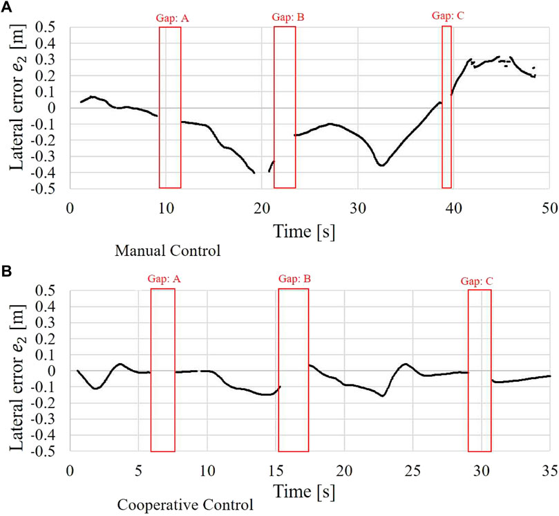
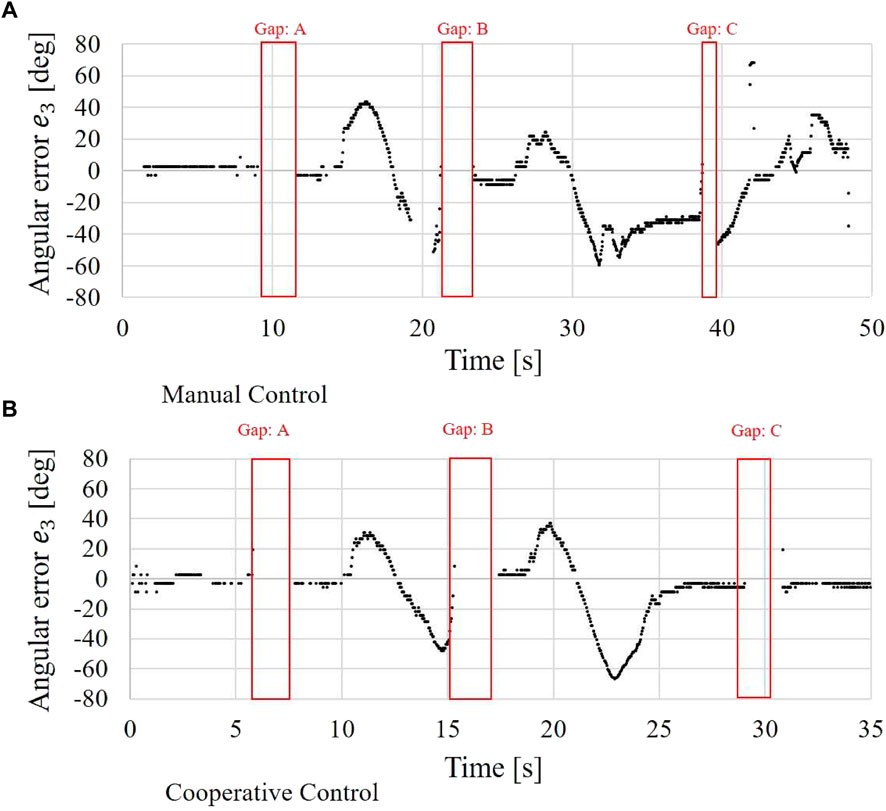
Figures 10, 11 show an example of the time-series data of the lateral error e2 and angular error e3, respectively, as defined in Figure 5. In both the figures, the upper and lower graphs show the MC and CC conditions, respectively.
A larger lateral error was found under the MC condition than under the CC condition. In particular, the path was lost from the camera image at approximately 20 s under the MC condition. However, under the CC condition, the error that occurred when the underwater robot reached the curves was immediately corrected by the operator. In addition, a smaller angular error was found under the CC condition than under the MC condition, and the operator could immediately correct the angular error after the curves under the CC condition.
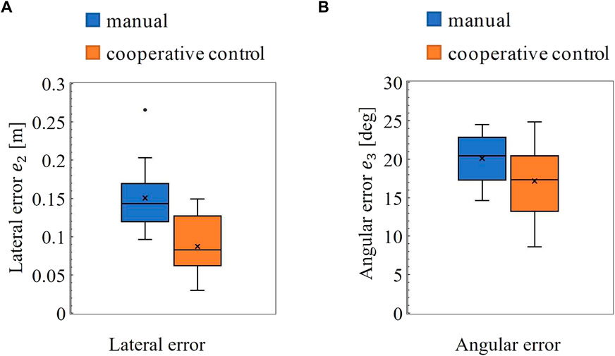
Figures 12A,B show the RMSE of the lateral and angular deviations. For the lateral error, the Shapiro–Wilk test and F-test revealed that the null hypotheses of normality (MC: p = 0.11, CC: p = 0.34) and equal variance (p = 0.29), respectively, were not rejected. Thus, a paired t-test was used for the significant test. The result showed that the lateral error under the MC condition was significantly larger than that under the CC condition (p = 0.000).
For the angular error, the Shapiro-Wilk test and F-test showed that the null hypotheses of normality (MC: p = 0.35, CC: p = 0.89) and equal variance (p = 0.090), respectively, were not rejected. Thus, a paired t-test was used for the significant test. Its result showed that the angular error in the MC condition was significantly larger than that in the CC condition (p = 0.039).
4.3 Completion time
The means of completion times required to follow the path were 41 s and 44 s for the MC and CC conditions, respectively, and no statistical significance was found (p = 0.35).
4.4 Attention allocation to objects recognition
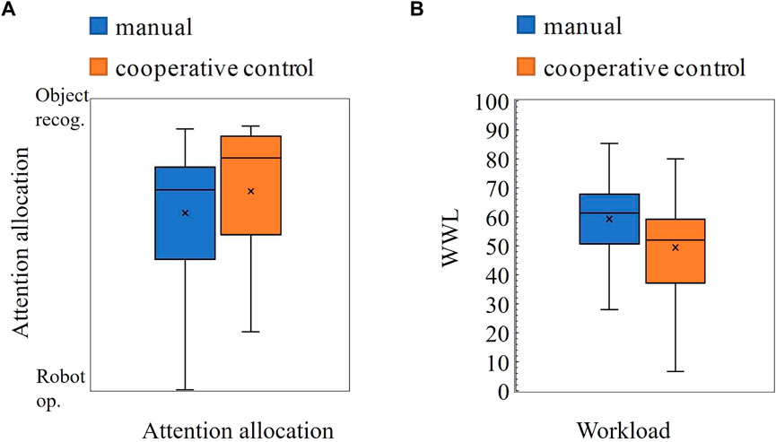
Figure 13A shows the results of the subjective responses of the attention allocation of the participants to the object recognition or path-following task. A higher value indicates that more attention is allocated to the object-recognition task than the path-following task of the robot. The Shapiro–Wilk test showed that the null hypothesis of normality was rejected (MC: p = 0.040, MC: p = 0.0034). The Wilcoxon signed rank test showed that the attention allocation of the participants was not significantly changed among the method conditions (p = 0.13), although the median under the CC condition tended toward object recognition.
4.5 Total workload
Figure 13B shows the WWL scores of NASA-TLX. The null hypotheses of normality (MC: p = 0.74, MC: p = 0.53) and equal variance (p = 0.29) between the method conditions were not rejected. The paired t-test showed that WWL in the CC condition was significantly smaller than that in the MC condition (p = 0.044).
5 Discussion
5.1 Interpretation of results
A cooperative path-following controller for object recognition tasks while following a path using an underwater robot was proposed. The results of the experiments indicated that the proposed method significantly reduced the tracking error in the lateral position, posture angle, and subjective workload compared to the conventional method, even in a situation where the path was interrupted in the middle of the path, and should be handled with only manual control without any assistance from the automatic control. The correct recognition rate of the object-recognition task and task execution time did not change significantly under the control-method condition. This result suggests that the support of the proposed method facilitates path-following by the operator, resulting in comparable task performance with less workload than with manual control.
The improvement in the path-following performance under the CC condition was more apparent in the lateral direction. This is because of the proposed concept of the human–machine collaboration method, in which the operator entrusts lateral control as much as possible when the robot functions correctly and humans are allowed to intervene in the posture control of the robot, which is more important for the object recognition task. Given the proposed method, the operator can directly intervene in the robot posture by the lateral joystick input and indirectly intervene in the longitudinal direction, which is controlled by the translational velocity conversion through posture control by controlling the joystick roll angle. It must be noted that the application of the CC tends to make the operator devote more attention to object recognition (Figure 13A), although the difference is not statistically significant. In the part where the path was not broken, the operator was only required to operate the joystick to vary the tilt angle, and the underwater robot could follow the path with the assistance of the system, while in the part where the path was broken, the operator was required to pay attention to the path-following task as well. The workload was significantly reduced by the proposed system; however, the workload increased under the CC condition for three of the sixteen participants. One possible explanation could be that the strength and timing of the system assistance were different from what the operator expected, although no clear explanation could be given. Understanding and resolving such human–machine conflicts (Saito et al., 2018; Okada et al., 2020) is an important issue that must be addressed in the future.
5.2 Contributions
Several studies have demonstrated that HSC can improve the performance of vehicle motion control through human–machine cooperation and reduce the workload. The results of the present study illustrate the same trend. For example, the introduction of HSC to the lane-keeping control of a surface vehicle has been shown to improve lane-following performance and overall performance by reducing the workload (Mulder et al., 2012; Nishimura et al., 2015). In addition, in controlling the movement of deep-sea vehicles to avoid obstacles, the path-following performance between obstacles has been improved (Wang, 2014). We studied the cooperative control of human and underwater robots using HSC. For example, a cooperative control method based on a simple proportional–derivative (PD) control law that performed object-recognition tasks while maintaining a stationary position and confirmed that it was effective in reducing the operator workload, has been proposed (Sakagami et al., 2022). In addition, in (Konishi et al., 2020), we conducted a study on a task similar to that presented in the current study. In the previous study (Konishi et al., 2020), a non-holonomic underwater robot that did not move directly in the lateral direction was considered, and the longitudinal and rotational motions of the robot were assigned to two-dimensional joystick motion; HSC was introduced in the lateral direction to reduce the operator workload in the path-following task. However, a simple control method using preview control, in which PD feedback for the predicted error in the future path was used, was applied; however, the convergence of the tracking error could not be theoretically guaranteed. Based on the results of this preliminary study (Konishi et al., 2020), the present study proposes a new cooperative path-following control method suitable for human–machine cooperation by designing an inverse optimal control for a holonomic underwater mobile robot. Using the proposed method, we demonstrated an improvement in the path-following performance and a reduction in the workload of the operator. The fact that the improvement in path-following performance is confirmed in the present study, which is not observed in the previous study (Konishi et al., 2020), can be regarded as the effectiveness of the proposed control law, although it is difficult to directly compare the results of the preliminary study and those of the present study owing to the differences in mechanisms, including the degrees of freedom. Furthermore, it must be noted that the control law proposed in this study can be easily applied to stationary control, as reported in (Sakagami et al., 2022), to achieve better control.
5.3 Limitations
When something is mistakenly recognized as a path, the proposed method may provide incorrect guidance. The direction angle β used for the translational velocity conversion cannot be directly changed by the operator, but the arbitrary motion of the robot can be achieved through posture change by the lateral joystick input. If the operator notices a misrecognition of the robot, the guidance can be temporarily stopped by the pressing of a button. In the present study, we demonstrate that the system can switch off the guidance control by setting e2 and e3 to zero when the system judges that the path detection has failed; thus, the robot can transfer the control to manual control and continue the task without any problem. It must be noted that a control discontinuity may occur when the assistance once turned off is turned back on, which may lead to an unstable phenomenon. A smooth control transition method using HSC has been proposed to eliminate control discontinuities in the control transition between the automated driving of automobiles and manual driving (Saito et al., 2018; Okada et al., 2020), which is expected to be applied to the problem.
6 Conclusion
6.1 Summary
In this study, we proposed a new cooperative path-following control method for underwater robots for visual object-recognition tasks while following a path to reduce the operator workload. In the proposed method, the design concept of the human—machine interface, including translational velocity conversion and haptic guidance for rotational motion, is combined with a path-following controller based on inverse optimal control. An experiment verified the effectiveness of the proposed method from the perspective of task performance and operator workload; the path-following performance was significantly improved, and the subjective workload was significantly reduced under the effect of the proposed method in comparison to manual control, even though the robot occasionally failed to detect the followed path.
6.2 Future research direction
In this study, the path-following problem was limited to a two-dimensional plane. Expansion of the proposed method to six-DoF motion in a three-dimensional space can be considered in a future study.
The effectiveness of the proposed control law was verified in an indoor pool without water flow. Therefore, conducting experiments in the presence of external disturbances, such as flow, especially in real environments, such as oceans and lakes, is a potential future course of action in this field of study.
Moreover, path-detection instability at the edge of the path was observed. Although the proposed method is effective throughout the system, it is necessary to consider more stable detectors in the future.
Data availability statement
The raw data supporting the conclusion of this article will be made available by the authors, without undue reservation.
Ethics statement
The studies involving human participants were reviewed and approved by the Research Ethics Committee of Nara Institute of Science and Technology (No. 2021-I-29). The patients/participants provided their written informed consent to participate in this study.
Author contributions
ES, TW, and NS contributed to conception and design of the study. ES, TW, HL, and YO contributed experimental design and data analysis. ES and NS made experimental devices. ES wrote the manuscript. All authors contributed to manuscript revision, read, and approved the submitted version.
Funding
This research was partially supported by JSPS KAKENHI Grant Number JP21H01294, Japan.
Acknowledgments
This manuscript has been released as a preprint at arXiv (Sato et al., 2022).
Conflict of interest
The authors declare that the research was conducted in the absence of any commercial or financial relationships that could be construed as a potential conflict of interest.
Publisher’s note
All claims expressed in this article are solely those of the authors and do not necessarily represent those of their affiliated organizations, or those of the publisher, the editors and the reviewers. Any product that may be evaluated in this article, or claim that may be made by its manufacturer, is not guaranteed or endorsed by the publisher.
References
Abbink, D. A., Mulder, M., and Boer, E. R. (2012). Haptic shared control: smoothly shifting control authority? Cogn. Technol. Work 14, 19–28. doi:10.1007/s10111-011-0192-5
Amundsen, H. B., Caharija, W., and Pettersen, K. Y. (2022). Autonomous rov inspections of aquaculture net pens using dvl. IEEE J. Ocean. Eng. 47, 1–19. doi:10.1109/joe.2021.3105285
Araki, R., Fukao, T., and Murakami, N. (2017). “Self gain tuning of robot tractors based on fuzzy reasoning (in japanese),” in Proc. of the Conference of the Society of Instrument and Control Engineers, January 13, 2017, Osaka, Japan (Kansai Branch and the Institute of Systems, Control and Information Engineers) 2016. rombunno.b3–1.
Azis, F., Aras, M., Rashid, M., Othman, M., and Abdullah, S. (2012). Problem identification for underwater remotely operated vehicle (rov): A case study. Procedia Eng. 41, 554–560. doi:10.1016/j.proeng.2012.07.211
Balasuriya, B., Takai, M., Lam, W., Ura, T., and Kuroda, Y. (1997). “Vision based autonomous underwater vehicle navigation: underwater cable tracking,” in Oceans ’97. MTS/IEEE Conference Proceedings, October 6–9, 1997 2, 1418–1424. (Nova Scotia, Canada: World Trade and Convention Centre Halifax)
Benloucif, A., Nguyen, A.-T., Sentouh, C., and Popieul, J.-C. (2019). Cooperative trajectory planning for haptic shared control between driver and automation in highway driving. IEEE Trans. Ind. Electron. 66, 9846–9857. doi:10.1109/TIE.2019.2893864
Choi, J., Lee, Y., Kim, T., Jung, J., and Choi, H.-T. (2017). Development of a rov for visual inspection of harbor structures. 2017 IEEE Underwater Technology (UT), 1–4.
Christ, R. D., and Wernli, R. L. (2014). “Introduction,” in The ROV manual. Editors R. D. Christ, and R. L. Wernli. Second Edition (Oxford: Butterworth-Heinemann), xxv–xxvi. doi:10.1016/B978-0-08-098288-5.00028-2
Flemisch, F., Abbink, D. A., Itoh, M., Pacaux-Lemoine, M.-P., and Weßel, G. (2016). Shared control is the sharp end of cooperation: Towards a common framework of joint action, shared control and human machine cooperation. IFAC-PapersOnLine 49, 72–77. Elsevier. doi:10.1016/j.ifacol.2016.10.464
Fukao, T. (2004). “Inverse optimal tracking control of a nonholonomic mobile robot,” in 2004 IEEE/RSJ International Conference on Intelligent Robots and Systems (IROS), September 28–October 02, 2004, Sendai, Japan (IEEE) 2, 1475–1480.
Haga, S., and Mizukami, N. (1996). Japanese version of nasa task load index sensitivity of its workload score to difficulty of three different laboratory tasks. Jpn. J. ergonomics 32, 71–79. doi:10.5100/jje.32.71
Hart, S. G., and Staveland, L. E. (1988). Development of nasa-tlx (task load index): Results of empirical and theoretical research. Adv. Psychol. 52, 139–183. Elsevier. doi:10.1016/s0166-4115(08)62386-9
Ho, G., Pavlovic, N., Arrabito, R., and Abdalla, R. (2011). Human factors issues with operating unmanned underwater vehicles. Proc. Hum. Factors Ergonomics Soc. Annu. Meet. 55, 429–433. doi:10.1177/1071181311551088
Jimin, H., Neil, B., and Shuangshuang, F. (2019). Auv adaptive sampling methods: A review. Appl. Sci. 9, 3145. doi:10.3390/app9153145
Kim, M.-G., Kang, H., Lee, M.-J., Cho, G. R., Li, J.-H., Yoon, T.-S., et al. (2020). Study for operation method of underwater cable and pipeline burying rov trencher using barge and its application in real construction. J. Ocean. Eng. Technol. 34, 361–370. doi:10.26748/ksoe.2020.034
Konishi, H., Sakagami, N., Wada, T., and Kawamura, S. (2020). “Haptic shared control for path tracking tasks of underwater vehicles,” in 2020 IEEE International Conference on Systems, Man, and Cybernetics (SMC), October 11–14, 2020, Toronto, ON (IEEE), 4424–4430.
Kuiper, R. J., Frumau, J. C., van der Helm, F. C., and Abbink, D. A. (2013). “Haptic support for bi-manual control of a suspended grab for deep-sea excavation,” in 2013 IEEE International Conference on Systems, Man, and Cybernetics, October 09-12, 2013, Manchester, United Kingdom IEEE, 1822–1827.
Kurashiki, K., Fukao, T., Osuga, K., Ishiyama, K., Takehara, E., and Imai, H. (2008). Robust control of a mobile robot on uneven terrain (in japanese). Trans. Jpn. Soc. Mech. Eng. 174, 2705–2712.
Lam, T. M., Mulder, M., and Paassen, M. V. (2007). Haptic interface for uav collision avoidance. Int. J. Aviat. Psychol. 17, 167–195. doi:10.1080/10508410701328649
Li, D., and Du, L. (2021). Auv trajectory tracking models and control strategies: A review. J. Mar. Sci. Eng. 9, 1020. doi:10.3390/jmse9091020
Mulder, M., Abbink, D. A., and Boer, E. R. (2012). Sharing control with haptics: Seamless driver support from manual to automatic control. Hum. Factors 54, 786–798. doi:10.1177/0018720812443984
Nishimura, R., Wada, T., and Sugiyama, S. (2015). Haptic shared control in steering operation based on cooperative status between a driver and a driver assistance system. J. Hum. Robot. Interact. 4, 19–37. doi:10.5898/4.3.nishimura
Okada, K., Sonoda, K., and Wada, T. (2020). Transferring from automated to manual driving when traversing a curve via haptic shared control. IEEE Trans. Intell. Veh. 6, 266–275. doi:10.1109/tiv.2020.3018753
Saito, T., Wada, T., and Sonoda, K. (2018). Control authority transfer method for automated-to-manual driving via a shared authority mode. IEEE Trans. Intell. Veh. 3, 198–207. doi:10.1109/tiv.2018.2804167
Sakagami, N., Suka, M., Kimura, Y., Sato, E., and Wada, T. (2022). “Haptic shared control applied for rov operation support in flowing water,” in Artif life Robotics.
Sato, E., Liu, H., Sakagami, N., and Wada, T. (2022). Cooperative path-following control of remotely operated underwater robots for human visual inspection task. arxiv V1, 1–8. doi:10.48550/ARXIV.2203.13501
Shimono, S., Toyama, S., and Nishizawa, U. (2016). “Development of underwater inspection system for dam inspection: Results of field tests,” in OCEANS 2016 MTS/IEEE Monterey, October 19–22, 2015, Washington, DC IEEE, 1–4.
Sontag, E. D. (1983). A lyapunov-like characterization of asymptotic controllability. SIAM J. Control Optim. 21, 462–471. doi:10.1137/0321028
Stefan, K., Jan, S., and Andre, S. (2015). “Effects of haptic guidance and force feedback on mental rotation abilities in a 6-dof teleoperated task,” in 2015 IEEE International Conference on Systems, Man, and Cybernetics, October 09–12, 2015, Hong Kong, China IEEE, 3092–3097.
Vaganay, J., Elkins, M., Esposito, D., O’Halloran, W., Hover, F., and Kokko, M. (2006). Ship hull inspection with the hauv: Us navy and nato demonstrations results. OCEANS 2006, 1–6.
Wada, T. (2019). Simultaneous achievement of driver assistance and skill development in shared and cooperative controls. Cogn. Technol. Work 21, 631–642. doi:10.1007/s10111-018-0514-y
Wang, K. (2014). Haptic shared control in deep sea mining: Enhancing teleoperation of a subsea crawler. Delft, Netherlands: Department of Mechanical Engineering Delft University of Technology. Available at: http://resolver.tudelft.nl/uuid:2054778b-7666-445a-b397-c3bd6b497ba5.
Keywords: shared control, ROVs, holonomic robot, human-machine system, cooperative control
Citation: Sato E, Liu H, Orita Y, Sakagami N and Wada T (2022) Cooperative path-following control of a remotely operated underwater vehicle for human visual inspection task. Front. Control. Eng. 3:1056937. doi: 10.3389/fcteg.2022.1056937
Received: 29 September 2022; Accepted: 28 November 2022;
Published: 08 December 2022.
Edited by:
Simon Rothfuß, Karlsruhe Institute of Technology (KIT), GermanyReviewed by:
Shi-Lu Dai, South China University of Technology, ChinaBalint Varga, Karlsruhe Institute of Technology (KIT), Germany
Copyright © 2022 Sato, Liu, Orita, Sakagami and Wada. This is an open-access article distributed under the terms of the Creative Commons Attribution License (CC BY). The use, distribution or reproduction in other forums is permitted, provided the original author(s) and the copyright owner(s) are credited and that the original publication in this journal is cited, in accordance with accepted academic practice. No use, distribution or reproduction is permitted which does not comply with these terms.
*Correspondence: Eito Sato, c2F0by5laXRvLnNkN0Bpcy5uYWlzdC5qcA==
 Eito Sato
 Hailong Liu
 Yasuaki Orita
 Norimitsu Sakagami
 Takahiro Wada