 Mohamed Radjeb Oudainia
 Chouki Sentouh
 Anh-Tu Nguyen
 Jean-Christophe Popieul2
95% of researchers rate our articles as excellent or good
Learn more about the work of our research integrity team to safeguard the quality of each article we publish.
Find out more
ORIGINAL RESEARCH article
Front. Control Eng. , 28 November 2022
Sec. Networked Control
Volume 3 - 2022 | https://doi.org/10.3389/fcteg.2022.1055915
This article is part of the Research Topic Model-based Methods for Human-Machine Cooperative and Shared Control Systems View all 6 articles
The work described in this paper proposes a new conflict minimisation strategy in shared driving control for lane keeping systems (LKS) in intelligent vehicles. This strategy takes into account a dynamic driver model, where the driver’s parameters are identified online using the Lyapunov approach. The design of an adaptive shared controller is based on the dynamic parameters of the driver model which changes according to the driver and the situation encountered. Based on Lyapunov stability arguments, the overall asymptotic stability of the closed-loop control system with the adaptive driver model and the variation of the vehicle speed is proved and an LMI optimization is used to formulate the control design. The simulation results, conducted with the SHERPA dynamic car simulator under real-world driving situations, show the importance of integrating a dynamic driver model in the controller design in order to decrease the conflict between the driver and the lane keeping system and to ensure the safety of the vehicle as well as to increase the confidence and acceptability of the driver.
Advanced driver assist systems (ADASs) such as lane keeping assist (LKA), adaptive cruise control (ACC), collision avoidance (CA) systems have been widely employed in commercial vehicles. These systems greatly reduce the workload of human drivers and reduce the risk of accidents, and crashes by warning or supporting the driver for particular manoeuvres (Rajamani, 2011). The ADASs developed for semi-autonomous driving scenarios can be categorized into human guided, human supervised and human assisted architectures (Flemisch et al., 2008). In recent works it has been established that driver-in-the-loop (DiL) human assisted ADAS architectures can be employed to address various human machine interaction (HMI) challenges inclusive of authority allocation (Abbink et al., 2011), transition of authority (Saito et al., 2018), conflict management (Nguyen et al., 2017), human driver workload reduction and skill enhancement (Wada et al., 2016). Such cooperative driving architectures have been explored for adaptive cruise control, collision avoidance systems, lane departure/keeping systems among other (Saleh et al., 2013; Schnelle et al., 2017). To design cooperative control architectures for ADAS, DiL architectures are typically formulated by integrating driver attributes such as workload, experience, and skill in the control design. For effective action which reflects such attributes various driver models based on neuromuscular dynamics (Sentouh et al., 2009), data driven (Li et al., 2016), hand impedance (Tanaka et al., 2010), vision/preview model have been developed (Nguyen et al., 2017). In this work, we explore the avenue of cooperative control for Lane Keeping Assist Systems (LKA) by considering the steering input (torque) as a control signal, focusing on the minimization of driver effort as well as the conflict between driver and system. Conflict between the human driver and the autonomous controller typically occurs when both agents have different actions for the same driving task. Such scenarios arise during transition of authority between the agents, sudden manoeuvres executed by driver/automation which is not predicted by the other agent and during extreme manoeuvres i.e. sharp curve negotiation.
Various cooperative control architectures have been proposed in (Saleh et al., 2013; Soualmi et al., 2014; Nguyen et al., 2017; Schnelle et al., 2017; Wang et al., 2017) based on DiL designs. In (Abbink et al., 2011; Mars et al., 2014; Boink et al., 2014) haptic feedback from steering wheel was used to ensure both driver and the autonomous controller participated in the driving action. In (Wada et al., 2016), a co-operative control approach for lane keeping based on H2 preview control was proposed by incorporating a nuero-muscular driver model. Similarly in (Soualmi et al., 2014), a haptic shared control between driver and e-copilot considered the use of driver torque as haptic feedback to design T-S fuzzy controllers for lane keeping. In (Wang et al., 2017), for varying driver steering characteristics such as delays, and preview time, a DiL gain-scheduling H∞ robust shared controller was proposed. In, (Wada et al., 2016; Saito et al., 2018) based on cooperative status detection, a conflict free smooth transition of authority between human driver and autonomous controller was proposed. Similarly in (Oudainia et al., 2022), conflict mitigation by adapting the cost function objective was proposed. Extending the work of (Nguyen et al., 2015), a co-operative control approach employing T-S models was proposed in (Nguyen et al., 2017) to perform lane keeping and conflict minimization simultaneously. In (Lv et al., 2018) a haptic control architecture was developed for smooth transition of control authority with adaptation to driver cognitive workload. The works in (Wada et al., 2016; Wang et al., 2017) assumed constant longitudinal speed in the design of lane keeping controllers. Further, conflicts between driver and the automated driving system was not explicitly addressed in (Oufroukh and Mammar, 2014; Wang et al., 2017). In (Nguyen et al., 2018), the unpredictable driver-automation interaction is explicitly taken into account in the shared control scheme, via a fictive driver activity variable. Similarly, (Wang et al., 2018) proposed a shared controller for path tracking considering different drivers’ characteristics to reduce the physical workloads of the inexperienced drivers. The concept of driver-automation oriented for shared control of lane keeping assist (LKA) was proposed in (Sentouh et al., 2018) based on two local optimal controllers combining system perception with robust control so that the proposed strategy can successfully share the control authority between human drivers and the LKA system. (Pano et al., 2020) presented a shared control strategy with a feedforward-feedback synthesis using a mixed H2/H∞ control involving both lane following performance and sharing capabilities indicators. This strategy is interesting as it used the sharing level between the human driver and the assistance explicitly. Moreover, the shared control proposed in (Zhao et al., 2020) is much more flexible since this work follow-up the study in (Pano et al., 2019). It aims to integrate the driver’s adaptation in the level of sharing over the driving task using cybernetic driver model. The control authority transition from automated functionality to a human driver is particularly studied in (Lv et al., 2021; Oudainia et al., 2022). This helps drivers to take control of the vehicle progressively. Recently, the shared control strategy have been studied considering driver’s behaviors to get a better cooperation. (Huang et al., 2019) presents a cooperative framework developed by adopting data-driven adaptive dynamic programming and an iterative learning scheme based on classical small-gain theory. In (Chen et al., 2020), the lane-keeping control method adopts a driver model based on near and far visual angles with a robust parallel distributed compensation H∞ controller. These approaches typically validated the cooperative performance of the DiL design for lane keeping tasks. Meanwhile, it is necessary to ensure that this new type of mobility takes into account both driver expectations and foreseeable changes in road user behavior (Sentouh et al., 2009). Overall, the shared control issue being able to share the driving responsibility with human drivers still remains challenging. It is therefore necessary to develop a new Human Machine Interaction strategy (HMI) that allows gradual shared control of vehicle commands between the vehicle and the driver.
Within this work, a novel shared control architecture shown in Figure 1, based on the dynamic of the driver’s visual and neruo-muscular parameters which are identified online will be developed and validated in real-time under various driving scenarios with the SHERPA-LAMIH driving simulator. This strategy considers the driver’s visual and neuro-muscular properties provide an adequate assistance for the driver’s abilities. Based on the principle of shared control, the algorithm must ensure the gradual transfer of control from the vehicle to the driver in the safest and most intuitive way for the driver in order to minimize the conflict between them.
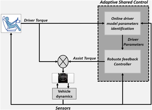
FIGURE 1. Online driver model parameters identification based shared control.
The featured contributions of this paper can be summarized in the following aspects:
• A new cybernetic driver model that takes into account the visual and the neuromuscular aspects is proposed (Section 2).
• The parameters of the driver model are estimated online by a new identification approach based on Lyapunov stability (Section 3).
• The aspects of real-time variation in the forward speed and the driver’s model parameters properties are treated in a polytope with finite vertices, and treated via the boundary domain (Section 4).
• The closed-loop stability of the Driver-Road-Vehicle system with the adaptive driver model and the variation in vehicle speed can be guaranteed using the Lyapunov stability arguments in the LMI control framework (Section 4).
The paper outline is as follows. The Driver-Road-Vehicle modeling is presented in Section 2. The online driver parameters identification approach is shown in Section 3 and the Driver-Automation shared control is designed in Section 4. Subsequently, in Section 5, the performance of the identification approach and the cooperative control scheme is validated in interactive simulation with the well-known SHERPA dynamic car simulator under real-world driving situations.
The design of the driver in the loop for cooperative control is carried out in this work for lane keeping, obstacle avoidance, and lane changing maneuvers. For an effective design of the cooperative driver controller, the integrated driver-road-vehicle model is discussed in this section.
The vehicle lateral dynamics as result of interaction between tires and road surface can be represented by the bicycle model (Rajamani, 2011). The lateral tire friction forces for a vehicle with front steering can be expressed as
where the linear front and rear slip angles are given as follows:
where δ is the wheel angle. The lateral side slip and yaw rate dynamics can be then given as (Sentouh et al., 2018),
where m is the mass of the vehicle, vx is the longitudinal velocity, β is the drift angle at the center of gravity, Iz is the vertical moment of inertia of the vehicle, r is the yaw rate, lf/lr is the distance between the front/rear axle and the center of gravity of the vehicle, fw is the lateral wind force having as its center of impact lw away from the center of gravity. Cf and Cr are the lateral stiffness coefficients of the front and rear pneumatic respectively.
For lane tracking purpose, the vehicle position error yL and the heading error ψL at a look-ahead distance lp are taken into account in the control design. The dynamics of these variables are given as follows (Sentouh et al., 2018),
where ρc is the curvature of the road. To represent the haptic interaction between the human driver and the vehicle, the dynamics of the steering column is represented as follows,
where δd is the steering wheel angle, Js is the equivalent moment of inertia of the steering system, and Bs is its equivalent damping coefficient. Td is the driver torque, and Ta is the assisting system torque. Where Rs is the reduction ratio between the steering wheel angle δd and the wheel angle δ. The self-aligning torque Ts is expressed as:
where ηt is the width of the tire contact.
It has been shown in the literature that the driver relies on two visual points to guide his vehicle on the road (McRuer et al., 1977; Donges, 1978), a far point allowing him to anticipate the evolution of the curvature and a near point which gives him a compensatory behaviour.
These points can be characterised by the two angles θnear and θfar as used in (Sentouh et al., 2009). The angle θfar represents the angle between the vehicle heading and the tangent to the curve. As for θnear, it represents the angle between the vehicle’s heading and the straight line connecting the vehicle’s centre of gravity and the point on the edge of the track, located at a distance of lp as illustrated in Figure 2.In this paper, the driver model proposes to take into account the visual aspect by considering the anticipatory and compensatory behavior of the driver as used in (Sentouh et al., 2009) combined with the neuromuscular aspect as used in (Bi et al., 2015). The architecture of the proposed driver model is shown in Figure 3.
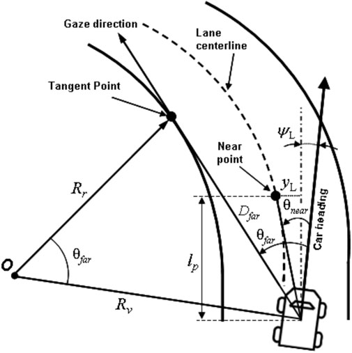
FIGURE 2. Visual angles for anticipatory and compensatory behaviour (Sentouh et al., 2009).
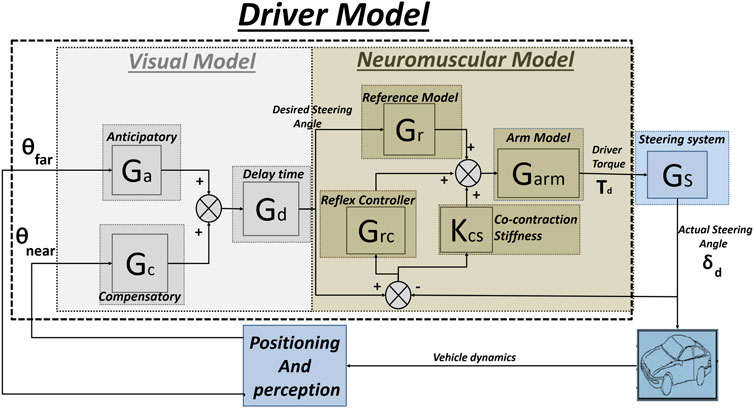
FIGURE 3. Architecture of the proposed driver model.
As used in (Sentouh et al., 2009), the visual model consists of three transfer blocks, Ga, Gc and Gd that represent respectively the anticipatory behaviour, the compensatory behaviour and the human processing delay time. In terms of anticipatory control, the driver predicts the future path of the vehicle and provides an anticipated steering input via the steering wheel before entering the curve. As for compensatory control, the driver adjusts the torque applied to the steering wheel by using visual information from the region near in front of the vehicle (the near visual angle θnear), in order to keep a safe lateral deviation from the centre of the lane. These transfers are modelled as (Sentouh et al., 2009):
which ka is the anticipation gain, TL and TI are the lead and delay time constants, respectively, and the gain kc represents the proportional action of the driver with respect to the error of the near visual angle and τd is the delay time.
Based on the model used in the (Bi et al., 2015), the neuromuscular model consists of four transfer blocks, Gr, kcs, Grc and Garm which represent respectively the reference model (feed-forward module), the stretch reflex controller, the co-contraction stiffness and the arm model. The reference model represents the angle-torque stiffness, which can provide a steering torque proportional to the desired angle. The co-contraction stiffness refers to the increase in the muscle’s intrinsic stiffness resulting from the activation of the muscle. The stretch reflex controller and the arm model represents the dynamics of muscle activation. These transfers are modeled as (Bi et al., 2015) and (Sentouh et al., 2009):
which kr is the feed-forward module, kcs the co-contraction stiffness, K and Br represent the stiffness and damping of the reflex, respectively, ωc is the cut-off frequency of the first order filter and Tn is the time constant of the arm system.
In order to design a shared control, the following simplified architecture of the proposed driver model is used:
According to the simplified architecture shown in Figure 4, the following driving model is used:
where K1(s), K2(s), K3(s) and Ud(s) are represented by the following transfer:
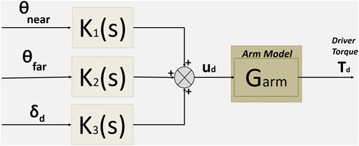
FIGURE 4. Simplified architecture of the proposed driver model.
To resume, and from (7) the driver model can be expressed in the form of the following state representation
where Td(t) is the driver torque,
where the new driver parameters used to design the shared controller are k1(t), k2(t) and k3(t) which represent the compensatory dynamics, the anticipatory dynamics, and the stiffness dynamics of the driver respectively. Tn is a constant, where its value is chosen as in (Sentouh et al., 2009).
In (8), K1(s), K2(s), and K3(s) are transfer functions (in the frequency domain), and in (10) are in the time domain where the latter are unknown (unknown temporal dynamics), so an online parameters identification using a Lyapunov (LP) approach is used to estimate them. This approach will be illustrated in the next section.
From the dynamics Eqs. 1–3 and Eq. 9 the driver-road-vehicle model can be formulated as follows:
where
with:
Our objective is to design an estimator for online parameters identification that guarantees the asymptotic stability of the closed-loop system (Eqs. 9,10) as shown in Figure 5.
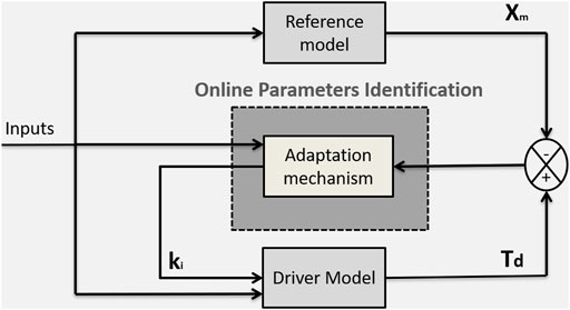
FIGURE 5. Diagram of the online driver parameters identification approach.
The identification scheme consists of three blocks. The first block is the proposed driver model with adjustable parameters Eq. 9. The second block is the adaptation mechanism where it contains the adaptation algorithm used for online parametres identification. The third block represents the reference model, the last one is a black box but it is described by the following equation in order to have the same form as the proposed driving model:
where Xm(t) represents the desired trajectory (the desired driving torque) that Td(t) in (9) must follow.
In this section we are going to present the adaptation mechanism used for the online parameters identification. We define by E(t) the tracking error E(t) = Td(t) − Xm(t) which satisfies the following equation
As adaptation algorithms, we propose:
with λ it is a positive adaptation parameter.
Theorem 1. Consider the system described by Eq. 9, and a reference model described by Eq. 12 whose input and state variable are bounded. If we apply the system input described by (10) to the system whose parameters are adjusted and identified by the algorithms Eq. 14 then the output of the closed-loop system is bounded for any bounded input signal, and the tracking error converges asymptotically to zero.
Proof: Let’s use the following quadratic Lyapunov function:
The derivation of the Lyapunov function (15) gives
replacing (Eq. 13) in (16) and after simplification we obtain
By using the adaptation and identification mechanism Eq. 14 we obtain
which is negative semi-definite. This implies that V(t) ≤ V (0) and thus that E(t), k1(t), k2(t) and k3(t), are bounded; thus Td(t) = E(t) + Xm(t) is also bounded and when we calculate the second derivative of the Lyapunov function we obtain:
replacing Eq. 13 in Eq. 19 and after simplification we obtain
As the inputs (θnear(t), θfar(t), δd(t)), E(t) and Td(t) are bounded then
This section first presents the T-S fuzzy representation of the integrated driver-in-the-loop vehicle model Eq. 11. Then, we provide in the second subsection an LMI-based solution for the driver-automation shared control problem, and in the last subsection we presents the stability analysis theory of the whole system.
Note that A and E in Eq. 11 depend on the following measured, identified and bounded terms:
With the approach of sector non-linearity (Wang and Tanaka, 2004), an exact T-S fuzzy model of Eq. 11 can be obtained with 26 = 64 linear sub-systems. However, this vehicle T-S fuzzy model leads to not only expensive numerical burden for real-time implementation but also conservative control results. Here, to reduce significantly the complexity and the conservatism of the proposed control method, the following change of parameter is performed:
where:
Note that the new parameter θ can be used to represent the variation of vx between its lower and upper bounds, i.e., θmin = −1, and θmax = 1. Then, the following first-element Taylor’s series around zero is used to exploit the strong relationship between the speed-dependent terms:
Remark that vx,
where Aijlm and Ei are calculated according to:
Moreover, the membeT-S fuzzy model are defined as follows:
To begin with, we define the performance output of Eq. 11 as
Note that β, r, ψL and yL represent lane tracking performance while
Problem 1. Consider the vehicle model system Eq. 23. Find a controller u such that:
• When w = 0, the closed-loop system is globally exponentially stable.
• When w ≠ 0, the closed-loop system has the input-to-state stability property with respect to the bounded curvature disturbance w.
Furthermore, the following performance index is minimized:For shared control design, we consider the control law:
where the control gains Fijlm, i, j, l, m ∈ {1, 2}, are to be determined. The following result provides a control solution for Problem 1, where our analysis is conducted using the following Lyapunov function:
Theorem 2. Consider a T-S fuzzy system as described in Eq. 23. The time-varying controller Eq. 25 stabilizes system Eq. 23 while minimizing the performance index Eq. 24 if there exist positive definite matrix X, matrices Mijlm, i, j, l, m ∈ {1, 2}, and positive scalars γ, ν, satisfying the following optimization:
Subject to
where
Moreover, the feedback gains in Eq. 25 can be computed as follows:
In this subsection, we are going to presents the stability analysis is provided of the whole system.
Proof. Multiplying Eq. 28 with hi(θ) ≥ 0, ηj (k1) ≥ 0,
For brevity, for any matrices of appropriate dimensions χi and Δijlm, ∀i, j, l, m ∈ {1, 2} we denote
Using successively Schur complement lemma, it follows that inequality Eq. 31 is equivalent to
where
where
where
• For free-disturbance system (i.e., w = 0),
• For disturbed system (i.e., w ≠ 0), it follows from Eq. 34 that
Since V(x) > 0, it follows from (35) that
where
The experimental validation involves the implementation in a LAMIH road vehicle dynamic simulator SHERPA as illustrated in Figure 6, which is used to demonstrate the effectiveness of the proposed driver model identification approach and the shared control approach. For a better presentation of the paper, this section is divided into two parts, the first part, we are going to validate the driver model and the identification approach by comparing this new approach of identification with the RLS (Recursive Least Square) approach and also validate the model in different test tracks. In the second part, we are going to made a comparison between our shared controller and the shared controller proposed in (Nguyen et al., 2017) for an obstacle avoidance scenario. The values for the vehicle’s mathematical parameter model (SHERPA) and for the controller are shown in Table 1, where the limits on k1, k2, k3, and
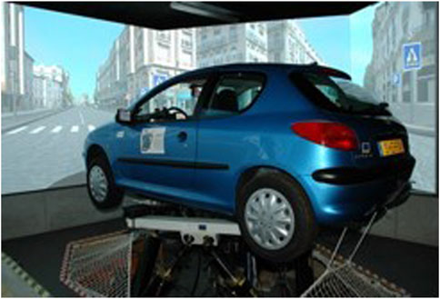
FIGURE 6. SHERPA driving simulator.
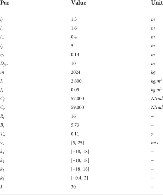
TABLE 1. Values for the vehicle’s mathematical parameter model (SHERPA) and for the controller.
This subsection is composed of two parts, the first one consists in the comparison between the proposed identification approach based on Lyapunov (LP) and the RLS approach, and the second part consists in the validation and analysis of the driver behaviour model in different tracks.
In this part, we are going to compare the proposed Lyapunov (LP) identification method with the recursive least square (RLS) method. This comparison is based on a reference model where the model has been created with known varying parameters in order to obtain reference parameters used for the comparison, the identification schema is shown in Figure 7.
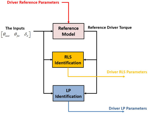
FIGURE 7. Architecture for the comparison of two identification approaches (RLS and LP approach).
The results of the identification by both methods are presented in Figure 8. As we can see, the proposed approach (LP) gives good results compared with that of the RLS method if we look at the tracking of the reference output, i.e. the tracking of the reference driver torque. The explanation of this advantage is shown in the parametric identification results where we can see that the parameters identified by the proposed (LP) approach match with the real reference model parameters compared with the RLS approach. So using (LP) approach will allow us to identify the true parameters of the driver model with the lowest tracking error.
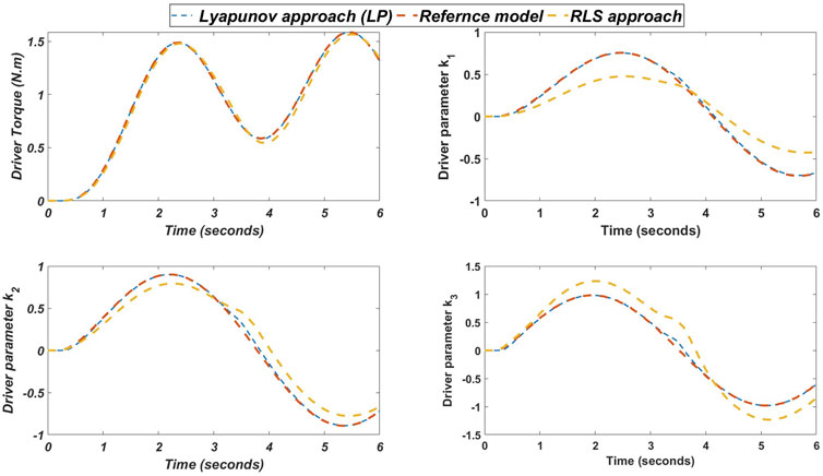
FIGURE 8. The results of the parametric identification by the two approaches (RLS and LP approach).
In order to analyze the behaviour of the driver in different situations, a parametric identification was made in manual driving mode for lane keeping in two different tracks for the same driver. The first track is the highway, with low curvature and a constant speed vx = 22 m/s, the second track is Satory, with high curvature and a constant speed vx = 14 m/s. The trajectory and curvature of the two tracks are shown in Figure 9.
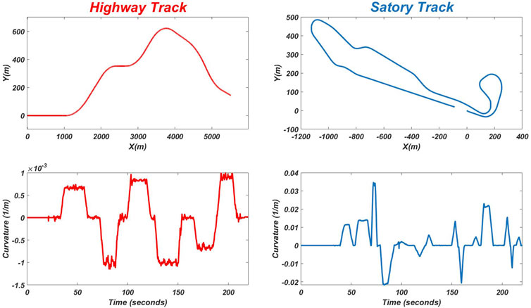
FIGURE 9. The trajectory and curvature for the highway track and the Satory track.
The results of the online identification of the driver’s parameters for the two tracks (highway and satory) are shown in Figure 10, Figure 11) respectively. As can be seen, the output of the model, i.e. the driving torque, matches perfectly with that of the simulator for both tracks. However, the parametric variation of the driver is not the same for both tests. We can therefore say that the driver’s behavior is not fixed but changes according to the situation he meets. It can also be noticed that the driver behaves like a linear model in the first track (highway) i.e. his parameters converge to a constant value compared to the second track where it behaves as a non-linear model. Also we can notice that the parameter which represents the compensatory dynamics in the first track is low compared to the two other parameters, and it can be explained that in the track where the road curvature is low (in a straight line) the driver does not focus much on lane keeping because for him it is easy, so he only gives importance to the other two parameters (anticipation and stiffness). Compared to the second track, where we see that the driver gives importance to the compensation because there are a lot of curves and the road curvature is high.
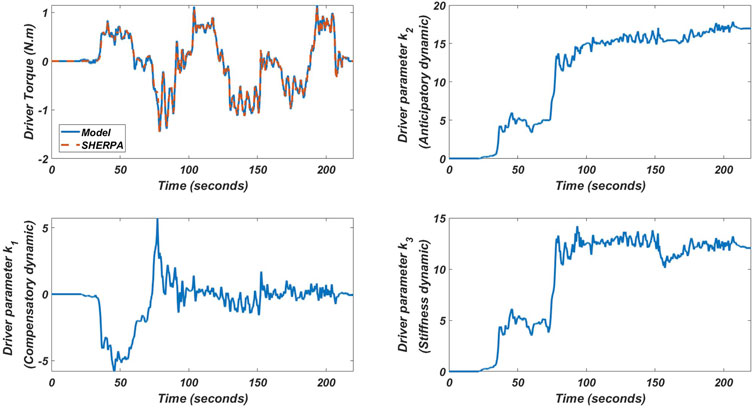
FIGURE 10. The results of the online identification approach of driver parameters in highway track for lane keeping test on the SHERPA simulator.
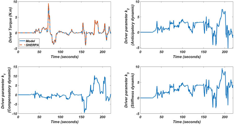
FIGURE 11. The results of the online identification of driver parameters in Satory track for lane keeping test on the SHERPA simulator.
In this subsection, we are going to made a comparison between our shared controller and the shared controller proposed in (Nguyen et al., 2017), the latter uses a shared control based on a driver model with constant parameters for a lane-keeping scenario (these parameters are obtained offline). This comparison is made in the case of an obstacle avoidance test in highway track, we placed three obstacles and asked three different drivers to avoid them by changing lanes in shared control mode. The test results are shown in Figure 12. It can be seen that the three drivers found it difficult to overtake the obstacle using the controller with constant driver parameters, where the driver and controller torques are high, compared to the proposed shared controller that uses the driver model with estimated parameters online, the three drivers can overtake the obstacle easily without applying high torque. This can be explained by the fact that if we use the same model with constant parameters for obstacle avoidance, the model may be invalid. This result confirms the results obtained in the identification phase shown in Figure 10, Figure 11, where it shows that the driver’s behavior changes depending on the situation encountered. All these results show the effectiveness of the proposed method in adapting the shared control to different scenarios and different drivers.
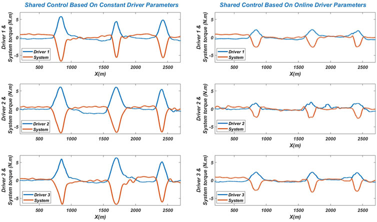
FIGURE 12. The shared controller based on constant and online driver parameters performance of an obstacle avoidance test on the SHERPA simulator.
In order to reinforce the results already obtained, an objective evaluation based on metrics to analyse the interaction of the driver with the system and the quality of control was done for the first driver. The interaction is evaluated through the torque exchanged and the angular velocity of the steering wheel during the test phase using the tow controllers, the controller based on constant driver parameters (Shared_CDP) and the proposed controller based on online driver parameters (Shared_ODP). To this end, four indicators were analyzed:
• The total steering effort provided by the driver StED (N.m2 for Steering Effort) during the period of experimentation (TEx):
• The total steering effort provided by the controller StEC (N.m2 for Steering Effort) during the period of experimentation (TEx)
• The conflict between the driver and the system during the period of experimentation (TEx):
• SW: This indicates the steering workload and is representative of the effort generated by both agents simultaneously for completing the driving task
The results of the objective analysis are presented in Figure 13. As we can see, the indicator of the effort provided by the driver and the system using a controller that does not take into account the driver’s behavior (Shared_CDP) is high compared to that of (Shared_ODP), this result shows that the proposed controller minimizes the effort applied by the driver in shared control mode and minimize the system effort in order to avoid saturation and overheating of the steering system motor. In addition, even if we compare the conflict indicator, we can clearly see that the (Shared_ODP) minimizes the conflict between the system and the driver in a dynamic way compared to the one that does not take the driver’s behavior in consideration (Shared_CDP). Comparing the last indicator, which represents the driving workload, it can be seen that the proposed controller minimizes the workload compared to the (Shared_CDP). So the proposed controller will allow us to minimize the driver effort, the system effort, the conflict between the driver and the system, and the workload on the steering wheel in shared control mode. The obtained results have strongly demonstrated the effectiveness of the proposed shared control method in the attenuation of driver effort and conflict between the lane keeping system and the driver.
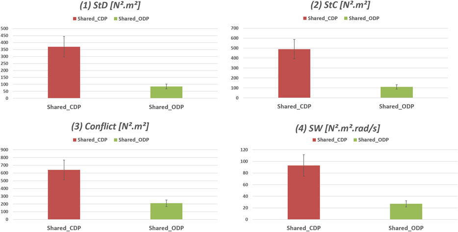
FIGURE 13. Objective evaluation results of the shared controller based on constant and online driver parameters for an obstacle avoidance test on the SHERPA simulator.
In this work, a new adaptive cooperative control strategy based on online driver’s parameters identification was presented in order to minimize the conflict between the lane keeping system and the human driver. A driver model that takes into account the visual and neuromuscular aspects was presented, where the latter was simplified for the shared control design. Then, a Lyapunov approach was presented for the online identification of driver parameters in order to make the driver model dynamic and personalized to each driver and each situation. The closed-loop stability of the Driver-Road-Vehicle system with the adaptive driver model and the variation in vehicle speed can be guaranteed using the Lyapunov stability arguments in the LMI control framework. The proposed approaches i.e. the identification approach and the shared controller approach are evaluated experimentally using a “full scale” SHERPA car simulator under real-world driving situation in obstacle avoidance scenarios. The obtained results have strongly demonstrated the effectiveness of the proposed shared control method in the attenuation of driver effort and conflict between the lane keeping system and the driver. In future work, we will focus on a polytopic representation with reduced system complexity and with a less conservative fuzzy control law.
The original contributions presented in the study are included in the article/supplementary material, further inquiries can be directed to the corresponding author.
All the authors listed have made an important contribution, both directly and intellectually, to the work and have approved it for publication.
This research has been done within the framework of the CoCoVeIA project (ANR-19-CE22-0009-01) funded by the Agence Nationale de la Recherche, the Ministry of Higher Education and Research and the French National Center for Scientific Research.
The authors gratefully acknowledge the support of these institutions.
The authors declare that the research was conducted in the absence of any commercial or financial relationships that could be construed as a potential conflict of interest.
All claims expressed in this article are solely those of the authors and do not necessarily represent those of their affiliated organizations, or those of the publisher, the editors and the reviewers. Any product that may be evaluated in this article, or claim that may be made by its manufacturer, is not guaranteed or endorsed by the publisher.
Abbink, D. A., Mulder, M., and Boer, E. R. (2011). Haptic shared control: Smoothly shifting control authority? Cogn. Technol. Work 14, 19–28. doi:10.1007/s10111-011-0192-5
Bi, L., Wang, M., Wang, C., and Liu, Y. (2015). Development of a driver lateral control model by integrating neuromuscular dynamics into the queuing network-based driver model. IEEE Trans. Intell. Transp. Syst. 16, 2479–2486. doi:10.1109/tits.2015.2409115
Boink, R., van Paassen, M. M., Mulder, M., and Abbink, D. A. (2014). “Understanding and reducing conflicts between driver and haptic shared control,” in 2014 IEEE International Conference on Systems, Man, and Cybernetics (SMC) (IEEE). doi:10.1109/smc.2014.6974130
Chen, W., Zhao, L., Wang, H., and Huang, Y. (2020). Parallel distributed compensation/h control of lane-keeping system based on the takagi-sugeno fuzzy model. Chin. J. Mech. Eng. 33, 61–13. doi:10.1186/s10033-020-00477-9
Donges, E. (1978). A two-level model of driver steering behavior. Hum. Factors 20, 691–707. doi:10.1177/001872087802000607
Flemisch, F., Kelsch, J., Loper, C., Schieben, A., Schindler, J., and Heesen, M. (2008). “Cooperative control and active interfaces for vehicle assistance and automation,” in FISITA World Automotive Congress.
Huang, M., Gao, W., Wang, Y., and Jiang, Z.-P. (2019). Data-driven shared steering control of semi-autonomous vehicles. IEEE Trans. Hum. Mach. Syst. 49, 350–361. doi:10.1109/thms.2019.2900409
Li, L., Liu, Y., Wang, J., Deng, W., and Oh, H. (2016). Human dynamics based driver model for autonomous car. IET Intell. Transp. Syst. 10, 545–554. doi:10.1049/iet-its.2015.0173
Lv, C., Wang, H., Cao, D., Zhao, Y., Sullman, M., Auger, D. J., et al. (2018). “A novel control framework of haptic take-over system for automated vehicles,” in 2018 IEEE Intelligent Vehicles Symposium (IV) (IEEE). doi:10.1109/ivs.2018.8500480
Lv, C., Li, Y., Xing, Y., Huang, C., Cao, D., Zhao, Y., et al. (2021). Human–machine collaboration for automated driving using an intelligent two-phase haptic interface. Adv. Intell. Syst. 3, 2170040. doi:10.1002/aisy.202170040
Mars, F., Deroo, M., and Hoc, J.-M. (2014). Analysis of human-machine cooperation when driving with different degrees of haptic shared control. IEEE Trans. Haptics 7, 324–333. doi:10.1109/toh.2013.2295095
McRuer, D. T., Allen, R. W., Weir, D. H., and Klein, R. H. (1977). New results in driver steering control models. Hum. Factors 19, 381–397. doi:10.1177/001872087701900406
Nguyen, A.-T., Sentouh, C., Popieul, J.-C., and Soualmi, B. (2015). “Shared lateral control with online adaptation of the automation degree for driver steering assist system: A weighting design approach,” in IEEE 54th Annual Conference on Decision and Control (CDC), 857–862.
Nguyen, A.-T., Sentouh, C., and Popieul, J.-C. (2017). Driver-automation cooperative approach for shared steering control under multiple system constraints: Design and experiments. IEEE Trans. Ind. Electron. 64, 3819–3830. doi:10.1109/tie.2016.2645146
Nguyen, A.-T., Sentouh, C., and Popieul, J.-C. (2018). Sensor reduction for driver-automation shared steering control via an adaptive authority allocation strategy. IEEE/ASME Trans. Mechatron. 23, 5–16. doi:10.1109/tmech.2017.2698216
Oudainia, M. R., Sentouh, C., Nguyen, A.-T., and Popieul, J.-C. (2022). “Dynamic conflict mitigation for cooperative driving control of intelligent vehicles,” in 2022 IEEE Intelligent Vehicles Symposium (IV) (IEEE), 1445–1452.
Oufroukh, N. A., and Mammar, S. (2014). “Integrated driver co-pilote approach for vehicle lateral control,” in 2014 IEEE Intelligent Vehicles Symposium Proceedings (IEEE). doi:10.1109/ivs.2014.6856519
Pano, B., Zhao, Y., Chevrel, P., Claveau, F., and Mars, F. (2019). Shared control based on an ecological feedforward and a driver model based feedback. IFAC-PapersOnLine 52, 385–392. doi:10.1016/j.ifacol.2019.09.062
Pano, B., Claveau, F., Chevrel, P., Sentouh, C., and Mars, F. (2020). “Systematic h 2/h haptic shared control synthesis for cars, parameterized by sharing level,” in 2020 IEEE International Conference on Systems, Man, and Cybernetics (SMC) (IEEE).
Saito, T., Wada, T., and Sonoda, K. (2018). Control authority transfer method for automated-to-manual driving via a shared authority mode. IEEE Trans. Intell. Veh. 3, 198–207. doi:10.1109/tiv.2018.2804167
Saleh, L., Chevrel, P., Claveau, F., Lafay, J.-F., and Mars, F. (2013). Shared steering control between a driver and an automation: Stability in the presence of driver behavior uncertainty. IEEE Trans. Intell. Transp. Syst. 14, 974–983. doi:10.1109/tits.2013.2248363
Schnelle, S., Wang, J., Su, H., and Jagacinski, R. (2017). A driver steering model with personalized desired path generation. IEEE Trans. Syst. Man. Cybern. Syst. 47, 111–120. doi:10.1109/tsmc.2016.2529582
Sentouh, C., Chevrel, P., Mars, F., and Claveau, F. (2009). “A sensorimotor driver model for steering control,” in IEEE International Conference on Systems, Man and Cybernetics (San Antonio, Texas, USA), 2462–2467.
Sentouh, C., Nguyen, A.-T., Benloucif, M. A., and Popieul, J.-C. (2018). Driver-automation cooperation oriented approach for shared control of lane keeping assist systems. IEEE Trans. Control Syst. Technol. 27, 1962–1978. doi:10.1109/tcst.2018.2842211
Sontag, E. D., and Wang, Y. (1995). On characterizations of the input-to-state stability property. Syst. Control Lett. 24, 351–359. doi:10.1016/0167-6911(94)00050-6
Soualmi, B., Sentouh, C., Popieul, J., and Debernard, S. (2014). Automation-driver cooperative driving in presence of undetected obstacles. Control Eng. Pract. 24, 106–119. doi:10.1016/j.conengprac.2013.11.015
Tanaka, Y., Kashiba, Y., Yamada, N., Suetomi, T., Nishikawa, K., Nouzawa, T., et al. (2010). “Active-steering control system based on human hand impedance properties,” in 2010 IEEE International Conference on Systems, Man and Cybernetics (IEEE). doi:10.1109/icsmc.2010.5642313
Wada, T., Sonoda, K., and Tada, S. (2016). Simultaneous achievement of supporting human drivers and improving driving skills by shared and cooperative control. IFAC-PapersOnLine 49, 90–95. doi:10.1016/j.ifacol.2016.10.467
Wang, H. O., and Tanaka, K. (2004). Fuzzy control systems design and analysis: A linear matrix inequality approach. John Wiley & Sons.
Wang, J., Zhang, G., Wang, R., Schnelle, S. C., and Wang, J. (2017). A gain-scheduling driver assistance trajectory-following algorithm considering different driver steering characteristics. IEEE Trans. Intell. Transp. Syst. 18, 1097–1108. doi:10.1109/tits.2016.2598792
Wang, J., Dai, M., Yin, G., and Chen, N. (2018). Output-feedback robust control for vehicle path tracking considering different human drivers’ characteristics. Mechatronics 50, 402–412. doi:10.1016/j.mechatronics.2017.05.001
Keywords: driver model parameter identification, advanced driving assistance system, cooperative control, lane keeping control, conflict minimization, adaptive control, identification for control
Citation: Oudainia MR, Sentouh C, Nguyen A-T and Popieul J-C (2022) Online driver model parameter identification using the Lyapunov approach based shared control. Front. Control. Eng. 3:1055915. doi: 10.3389/fcteg.2022.1055915
Received: 28 September 2022; Accepted: 14 November 2022;
Published: 28 November 2022.
Edited by:
Yong Xu, Guangdong University of Technology, ChinaReviewed by:
Danica Rosinová, Slovak University of Technology in Bratislava, SlovakiaCopyright © 2022 Oudainia, Sentouh, Nguyen and Popieul. This is an open-access article distributed under the terms of the Creative Commons Attribution License (CC BY). The use, distribution or reproduction in other forums is permitted, provided the original author(s) and the copyright owner(s) are credited and that the original publication in this journal is cited, in accordance with accepted academic practice. No use, distribution or reproduction is permitted which does not comply with these terms.
*Correspondence: Mohamed Radjeb Oudainia, TW9oYW1lZC5PdWRhaW5pYUB1cGhmLmZy
Disclaimer: All claims expressed in this article are solely those of the authors and do not necessarily represent those of their affiliated organizations, or those of the publisher, the editors and the reviewers. Any product that may be evaluated in this article or claim that may be made by its manufacturer is not guaranteed or endorsed by the publisher.
Research integrity at Frontiers
Learn more about the work of our research integrity team to safeguard the quality of each article we publish.