 John A. Tetteh
 István Z. Kiss
- Department of Chemistry, Saint Louis University, St. Louis, MO, United States
We investigate the dynamical behavior of the oscillatory electrodissolution of nickel and hydrogen reduction reaction in a closed electrochemical bipolar cell with two nickel wires. In the bipolar setup, two-half U cells are separated by an epoxy plate with the two embedded nickel electrodes; the oxidation and reduction reactions take place at the two ends of the same wire. The electrode potential oscillations were found to be strongly synchronized with 1 mm diameter electrodes in an in-phase configuration. Because experiments in similar configurations with traditional (three-electrode) cell showed no synchronization of the oscillatory anodic nickel electrodissolution, the introduction of the cathodic side of the bipolar electrodes induced the synchronization. The results were interpreted with a model that considered the kinetically coupled cathode-anode dynamics as well as interactions on the cathode and the anode side through migration current mediated potential drops in the electrolyte. The electrical coupling strength was calculated from solution resistance and charge transfer resistance measurements. The theory correctly interpreted that the bipolar cell with large (1 mm diameter) electrodes exhibits strong coupling with synchronization, and the bipolar cell with small (0.25 mm diameter) electrodes and the traditional configuration exhibit weak coupling and thus desynchronization. The experiments demonstrate the use of bipolar electrochemical cells for the investigation of collective behavior of electrochemical processes and the proposed approach holds promise for the design of bipolar multi-electrode arrays with engineered coupling to promote sensing and information processing using microchips.
1 Introduction
Bipolar electrochemistry (Koefoed et al., 2017) have gained much interest in the field of material science (Loget et al., 2013), industrial applications (Duval et al., 2001), biological systems (Morse et al., 2011), in particular, with respect to addressing chemical reactions at micro and nanoscales (Loget and Kuhn, 2011). Bipolar electrochemistry diverges from traditional electrochemistry in both its fundamental concept and practical applications–the potential drop that drives the electrochemical reaction is imposed in a wireless process where asymmetric electrochemical reactions unfold simultaneously at the opposing ends of a single conductive entity known as a bipolar electrode (Fosdick et al., 2013; Crooks, 2016). These reactions are remotely regulated by adjusting the electric field across an electrolytic solution that envelops the bipolar electrode (Crooks, 2016). Remarkably, without any physical connection to an external electrical circuit, it becomes feasible to initiate desired reactions concurrently even across multiple bipolar electrodes, ranging from small arrays to extensive ensembles comprising thousands of electrodes (Mavre et al., 2010). Furthermore, this technique accommodates the use of electrodes at various scales, including macroscopic, microscopic, and nanoscopic levels (Sentic et al., 2015). This versatility is particularly compelling for materials modification, as it induces an asymmetrical alteration of the objects involved (de Poulpiquet et al., 2023).
The study of electrochemical oscillators (Hudson and Tsotsis, 1994; Krischer, 2002; Orlik, 2012a) has led to the discovery of a variety of synchronization phenomena using electrode arrays (Wickramasinghe and Kiss, 2012), ranging from in- and anti-phase synchronization of oscillator pairs to emergence of synchrony, cluster states, and chimeras of oscillator populations (Mukouyama et al., 1996; Kiss et al., 1999; Wang et al., 2000; Kiss et al., 2002; Karantonis et al., 2004; Kiss et al., 2005; Varela et al., 2005; Wickramasinghe and Kiss, 2013; Ocampo-Espindola et al., 2019). The emergence of these synchronization patterns has been attributed to electrical coupling through potential drops in the electrolyte (Mukouyama et al., 1996) and external resistance interface (Kiss et al., 1999; Wickramasinghe and Kiss, 2013) that can overcome desynchronizing factors such as surface heterogeneities and chaotic dynamics (Wang et al., 2000; Kiss et al., 2002; Kiss et al., 2005; Cruz et al., 2007). Synchronization behavior of electrochemical oscillators can be used to decrypt electrical coupling in multielectrode devices (Jia and Kiss, 2017); this electrical coupling can play important role in wide range of electrochemical applications, for example, with generator-collector or collector-collector configurations of electrochemical microsensors (Amatore et al., 2008).
Nonlinear dynamics phenomena have been thoroughly explored in the traditional three electrode configuration (Orlik, 2012a; Orlik, 2012b). In these configurations, far-from-equilibrium nonlinear electrochemical oxidation (or reduction) are studied. However, in electrochemical systems the interactions between the cathode-anode systems can also be investigated (Ferrari and Massardo, 2013; Wickramasinghe and Kiss, 2016). Even though coupling induced synchronization and clustering behavior was explored in the traditional three electrode configuration (Wang et al., 2000; Wang et al., 2002), it is also possible to observe these behaviors in cathode-anode systems (Hankins et al., 2017; Hankins et al., 2019). The non-linear behavior of the coupled anodic nickel electrodissolution and hydrogen ion reduction was explored in various cathode-anode configurations (Wickramasinghe and Kiss, 2016; Hankins et al., 2017; Hankins et al., 2019). With a single cathode and a single anode, bistability and current oscillations were observed depending on the size of the cathode without any external resistance (Wickramasinghe and Kiss, 2016). Oscillations occurred only at intermediate cathode areas and were interpreted by the enhanced charge-transfer resistance of the cathode reaction. The coupling mechanism and the extent of synchronization of oscillatory nickel electrodissolution with two anodes in the presence of a common cathode were also studied (Hankins et al., 2017). The synchronization patterns were analyzed by changing the size ratio between the anode and cathode. The findings showed that hydrogen ion reduction on a single (common) cathode reaction can effectively couple the nickel electrodissolution reactions in dual anode configuration. Additionally, it was shown that the coupling imposed by a single (fast) cathodic reaction in the presence of a multi-electrode oscillatory anode reaction is similar to quorum sensing (Hankins et al., 2019). It was shown that starting with a large electrode array and decreasing the number of electrodes a transition occurs to oscillations and thus an “inverse” dynamical quorum transition takes place. These studies of nonlinear dynamics of coupled cathode-anode systems used traditional cell configuration with a separate cathode and anode.
In a recent study using an electrochemical bipolar cell, the oscillatory electrodissolution and hydrogen ion reduction was studied using a single nickel wire (Liu and Kiss, 2023). It was shown that current oscillations without external resistance is possible in the bipolar system. Additionally, tuning the concentration on the anode and cathode, the current level and the dynamics of the oscillations can be changed as well.
In this paper, we investigate the synchronization of electrode potential oscillations of two nickel electrodes in a closed bipolar system. The bipolar system is a U cell with the anodic and cathodic compartments (with 3.00 M and 0.01 M H2SO4 electrolyte, respectively) separated by epoxy with two embedded nickel electrodes. Chronopotentiometry is employed to study the synchronization of electrode potential oscillations during the concurrent nickel eletrodissolution and hydrogen ion reduction in the bipolar system. The obtained results are compared to those obtained in traditional three-electrode configurations and two electrode (single cathode - two anode) system with the application of external resistance, where the oscillations are induced by the total cell resistance. The extent of synchronization is determined for relatively large (1 mm diameter) and small (0.25 mm diameter) electrodes. The emergence of synchronized oscillations is interpreted with a model that evaluates the electrical coupling strengths between electrodes using the solution series resistances and the charge transfer resistance of the hydrogen ion reduction reaction.
2 Experimental methods
2.1 Traditional three electrode cell
For the traditional three electrode system, the electrochemical cell (half U cell configuration) consists of two 1.00 mm diameter nickel working electrodes (WE1 and WE2), a Hg/Hg2SO4/saturated K2SO4 reference electrode, a 1.6 mm diameter platinum rod counter electrode in 3.00 M H2SO4 solution as shown in Figure 1A. Individual resistance of 1 kohm was connected to each of the two nickel working electrodes. The electrodes were wet polished with a series of sandpapers (P180-P4000) with a Buehler Metaserv 3000 polisher before the experiments. The nickel electrodes were connected to a Gamry potentiostat through an individual resistance on each electrode. Electrochemical impedance spectroscopy was also performed to measure the solution resistances as well as the charge transfer resistance.
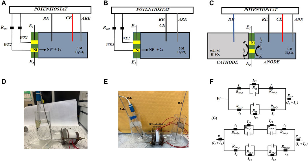
Figure 1. Experimental setup and schematics. (A) Schematic of two Ni working electrodes (WE1 and WE2) embedded in epoxy, in a half U traditional electrochemical cell. (B) Schematic of two Ni working electrodes (WE1 and WE2) embedded in epoxy, in a half U cathode-anode electrochemical cell. (C) Schematic of two Ni working electrodes (WE1 and WE2) embedded in epoxy, in a bipolar cell configuration, (D) Photo of cell configuration with the half U cell. (E) Photo of cell configuration with the bipolar cell. (F) Equivalent circuit of the traditional electrochemical cell (G) Equivalent circuit of the bipolar electrochemical cell. E1 and E2: electrode potential; IF1,2: Faradaic current; Cd: double-layer capacitance; I1,2: current; Rs: solution resistance, Rc: collective resistance, V: circuit potential. RE: reference electrode. CE: counter electrode. DE: driving electrode. ARE: auxiliary reference electrode.
The same cell was also used to study oscillations in the traditional two-electrode cell (see Figures 1B, D) with two nickel wires (used as the working) and a single cathode Pt wire (used as the RE and CE electrodes).
2.2 Closed bipolar electrochemical cell
For the bipolar cell, two nickel electrodes were embedded in epoxy with both ends of the nickel uncovered. A closed bipolar system was made with two different compartments as seen in Figures 1C, E. In the closed bipolar system, platinum electrode is the driving electrode (connected to the working electrode point of the potentiostat) which applies an anodic potential. In the same compartment, which is referred to as the cathodic compartment, hydrogen reduction takes place on the surface of the bipolar electrode. In the other compartment, which we refer to as the anodic compartment, nickel electrodissolution takes place on the (opposite) surface of the nickel electrode; the same compartment accommodates the RE and CE electrodes connected to the potentiostat. The anodic and cathodic compartments are filled with 3.00 M and 0.01 M H2SO4 electrolytes respectively. The two compartments in the cell are separated by two bipolar nickel electrodes embedded in an insulator (epoxy). Two different sizes of nickel electrodes consisting of d = 0.25 mm and 1.00 mm were used in the experiment. The oscillations of the electrode potentials were recorded using chronopotentiometry with connecting a wire (embedded in the epoxy) to the bipolar electrodes and measuring the potential with respect to a Ag/AgCl/2 M NaCl auxiliary reference electrode placed in the anodic side of the bipolar electrode.
2.3 Data analysis
The frequency of the oscillations was calculated based on phase description of oscillators (Pikovsky et al., 2003). The Hilbert transform of the time series of a signal
was used in defining the phase (Pikovsky et al., 2003);
where
3 Results and discussion
3.1 Experimental results
3.1.1 Nickel electrodissolution in the traditional electrochemical system
To better understand the complex dynamics in the bipolar system, we first demonstrate the behavior of (anodic) nickel electrodissolution using two electrodes in a traditional electrochemical system (Figure 1A) with two working, one reference, and one counter electrode. In Figure 2A, the times series of electrode potential oscillations are shown at a constant circuit potential V = 1090 mV with individual external resistances of Rind = 1 kohm. (Without adding an external resistance the system does not exhibit oscillations (Kiss et al., 1999)). The electrode potential oscillations do not overlap and have different frequencies (f1 = 1.032 Hz and f2 = 1.047 Hz) which suggest that the two oscillators are not synchronized and thus not (or very weakly) coupled. This lack of synchronization is further confirmed in Figure 2B, where the phase difference between the two oscillators are plotted with respect to time: phase drifting behavior confirms the absence of synchrony. This lack of synchrony without added coupling can be observed at other circuit potentials as well. Figure 2C shows the frequencies of the two oscillators as a function of the circuit potential for the entire region of oscillations. Close to the onset of oscillation at V = 1070 mV the frequencies have lower (but distinct) values of f1 = 0.998 and f2 = 1.009 Hz. With increasing V, the frequencies of the two oscillators increased to a maximum of f1 = 1.045 and f2 = 1.074 Hz at V = 1110 mV after which they to decreased to f1 = 0.810 Hz and f2 = 0.824 Hz at V = 1190 mV. The different frequency values of the two electrochemical oscillators determined in the large circuit potential range indicates lack of synchronization and thus weak coupling.
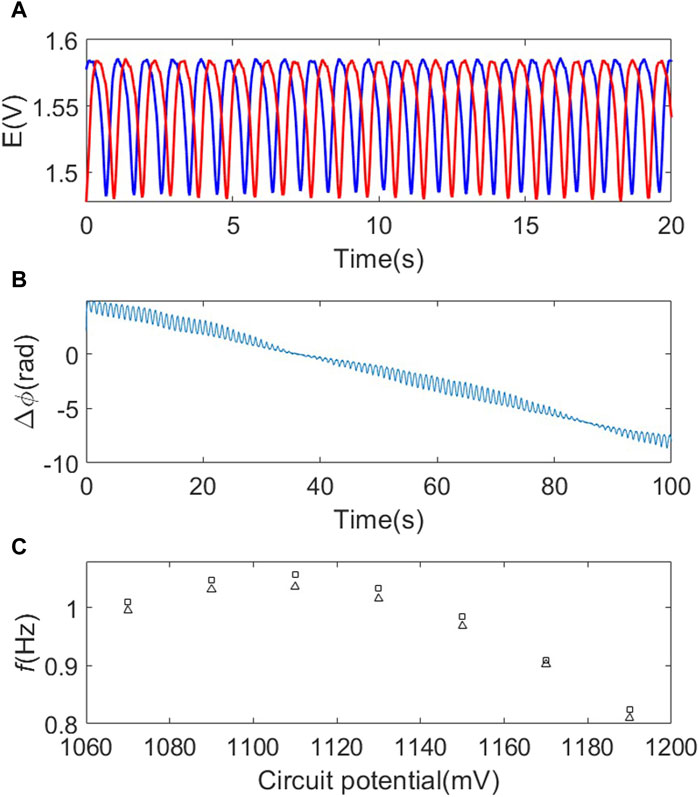
Figure 2. Desynchronized electrode potential oscillations in the traditional three-electrode electrochemical system (d=1.00 mm) (A) Time series of the electrode potential oscillations (WE1 (blue) and WE2 (red); V= 1090 mV. (B) Phase difference vs. time plot of the two oscillators. V=1090 mV. (C) Circuit potential vs. frequencies (d=1.00 mm). Rind = 1 kohm.
3.1.2 Nickel electrodissolution in two-electrode (cathode-anode) system
For reference, we also show the behavior with oscillatory nickel electrodissolution using two nickel wires coupled to a (relatively large surface area corresponding to the driving electrode, A = 69 mm2) cathode (see Figure 1B for schematic of the setup). External resistance (Rind = 1 kohm) was again needed to obtain current (and thus electrode potential) oscillations. In Figure 3A, the times series of electrode potential oscillations are shown at a constant circuit potential V = 1.780 V. The electrode potential oscillations do not overlap and have different frequencies (f1 = 0.987 Hz and f2 = 1.014 Hz). Accordingly, the phase difference time series (Figure 3B) exhibits phase drifting, which suggests that the two oscillators are not synchronized and thus not (or very weakly) coupled. This lack of synchronization was also observed at other circuit potentials as shown in Figure 3C; the frequencies exhibit a maximum at V = 1.800 V but are also different (14–45 mHz) at each potential. Therefore, similar to those observed with the traditional three electrode setup, the lack of synchronization indicates weak coupling.
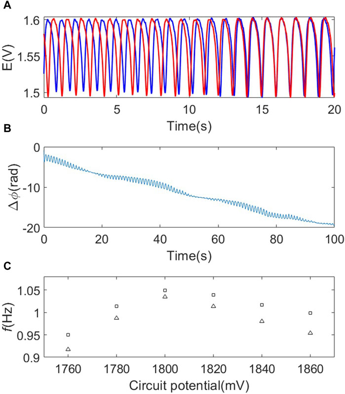
Figure 3. Desynchronized electrode potential oscillations in the cathode-anode system (A) Time series of the electrode potential oscillators WE1 (blue) and WE2 (red); V= 1780 mV. (B) Phase difference vs. time plot of the two oscillators; V=1780 mV. (C) Circuit potential vs. frequencies (d=1.00 mm). Rind = 1 kohm.
3.1.3 Nickel electrodissolution in the bipolar electrochemical system with relatively large electrodes
Next, we performed experiments with two 1.00 mm diameter nickel electrodes in the closed bipolar electrochemical system. In the closed bipolar system, two platinum rod electrodes were used as the driver (DE) and counter electrodes (CE) respectively and an anodic (V > 0) potential was applied. Hydrogen reduction is induced in the cathodic compartment with the driving electrode (DE). In the other, anodic compartment of the bipolar cell, Ni is oxidized to Ni2+ and various forms of oxides can form along with water electrolysis. In this bipolar configuration, electrode potential oscillations (see Figure 4A) were observed at relatively large circuit potential V = 3.72 V even without an individual resistance. However, in contrast to the previous examples, the electrode potentials nearly overlap, and the frequencies are the same f1=1.137 Hz and f2 = 1.137 Hz. Similarly, the phase difference time series in Figure 4B shows phase locking with a mean phase difference
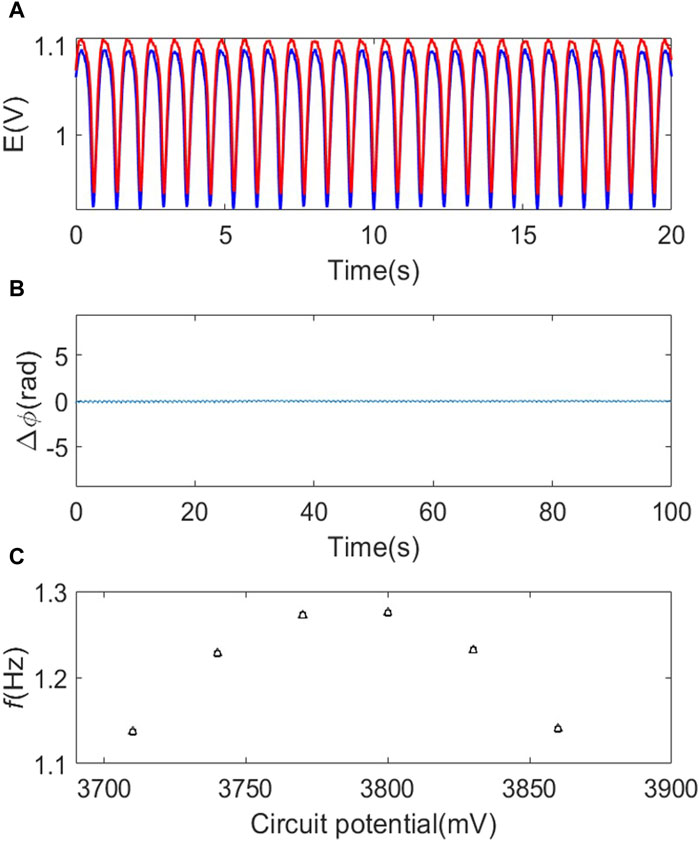
Figure 4. Synchronized electrode potential oscillations in the bipolar system (d=1.00 mm). (A) Time series of the electrode potential oscillators WE1 (blue) and WE2 (red); V= 3720 mV (B) Phase difference vs. time plot of the two oscillators; V=3720 mV. (C) Circuit potential vs. frequencies.
3.1.4 Nickel electrodissolution in the bipolar electrochemical system with small electrodes
We also performed experiments with a smaller electrode diameter d = 0.25 mm using the bipolar configuration. With these smaller nickel electrodes, electrode potential oscillations could also be observed without an external resistance; the results are shown at V = 2.85 V in Figure 5A. While the oscillatory behavior occurred without an external resistance, similar to those with the large wires in the bipolar cell, the electrode potential oscillations now show unsynchronized behavior: the electrode potential oscillations do not overlap, the oscillators have different frequencies (f1 = 1.060 Hz and f2 = 1.079 Hz), and the phase differences diverge (see Figure 5B). The lack of synchronization thus indicates a weakened coupling with the small electrodes. This lack of synchronization was observed for a wide circuit potential region 2820 mV
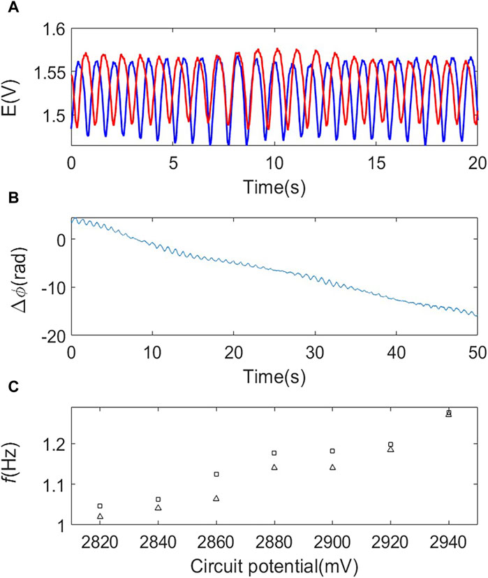
Figure 5. Desynchronized electrode potential oscillations in the bipolar system (d=0.25 mm). (A) Time series of the electrode potential oscillators WE1 (blue) and WE2 (red); V= 2850 mV. (B) Phase difference vs. time plot of the two electrodes; V= 2850 mV. (C) Circuit potential vs. frequencies.
3.2 Theory and numerical simulations
3.2.1 Theory: Coupled electrochemical oscillators through individual and collective resistors
Interactions between the electrodes in a cell can be described through developing a kinetic model for the electrochemical reactions. Such model can be constructed by the mass and charge balance equations (Kiss et al., 1999). First, we consider the traditional cell with two working electrodes (see Figure 1A) with an equivalent circuit in Figure 1F. The two electrodes are connected to the potentiostat through individual external resistances (Rext,a). The electrodes have surface area A and specific double capacitance Cd. The currents generated by each electrodes (I1 and I2) are obtained from double layer charging and charge transfer processes:
where JF,1 and JF,2, are the Faradaic current densities, E1 and E2 are the electrode potentials. At the electrolyte side, there is a potential drop, which in general requires solving Laplace equation. Here we apply a simplified approach, where the potential drop in the electrolyte is modeled through a combination of parallel (Rind,a) and collective (Rc,a) resistances. The potentiostat maintains constant circuit potential, V, therefore:
By combining Eqs 3–6, the differential equations for the dynamical evolution of the electrode potentials are obtained:
where the coupling strength k can be calculated as
In Eq. 9,
To complete the model, the Faradaic current density functions (JF) must be provided considering the kinetics of the nickel electrodissolution process. The model is based on a kinetic scheme (Haim et al., 1992) with two dimensionless variables for each oscillator
where
(Note that there is direct scaling between coupling strength with and without dimensions,
The effect of the (dimensionless) coupling strength
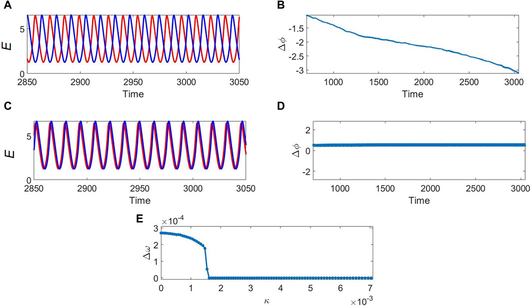
Figure 6. Numerical simulation of oscillatory electrode potential time series with weak and strong coupling. (A) Time series of the electrode potential oscillators WE1 (blue) and WE2 (red) and (B) phase difference vs. time plot with weak coupling;
In relevance to the experimental results, one explanation for the change from lack of synchronization in the traditional cells and the bipolar cell with small surface area to nearly full synchronization in the bipolar cell with large surface area is the increased electrical coupling through potential drops in the electrolyte. To test this explanation, we evaluate the total and the collective cell resistances in the different cells, calculate the electrical coupling strengths, and correlate the coupling strengths with the experimentally observed extent of synchronization.
3.2.2 Experimental evaluation of coupling strength in the traditional cell
In order to apply Eq. 9 to calculate the coupling strength, the total collective resistance
Then, the solution resistance was measured when both electrodes are connected (
By comparing Eqs 13, 14,
The two solution resistances were measured using impedance spectroscopy and we found that
3.2.3 Experimental evaluation of coupling strength in the bipolar cells
Dynamics of the bipolar cell (Figure 1C) can be represented with an equivalent circuit in Figure 1G. The anode and cathode dynamics are represented with parallel capacitance and the (nonlinear) charge transfer resistance. Coupling can occur on both sides of the cell with combination of individual and collective resistances due to ohmic potential drop in the electrolyte. The previous study showed that the oscillation of a single bipolar electrode can be understood in the nickel dissolution/hydrogen evolution system by considering the nonlinearities of the nickel dissolution and representing the cathode with its charge transfer resistance measured at the potential that corresponds to the current level of the oscillations. (Liu and Kiss, 2023). The current level at the oscillation onset for a single electrode was I = 435 μA; we performed an electrochemical impedance spectroscopy analysis with a traditional configuration with the 0.01 M H2SO4 (corresponding to the cathode compartment). At I= −435 μA (corresponding to V= −1292 mV vs. Hg/Hg2SO4/sat’d K2SO4), we found that the charge transfer resistance is
Another aspect of the bipolar cell is the presence of ohmic drop in the electrolyte on the cathodic side and thus coupling. We assume that this coupling also occurs through combination of individual and collective resistances as shown in Figure 1F. These resistances can be calculated with the same procedure as that for the anode side. The series resistance of a single cathode and the two short-circuited cathodes were
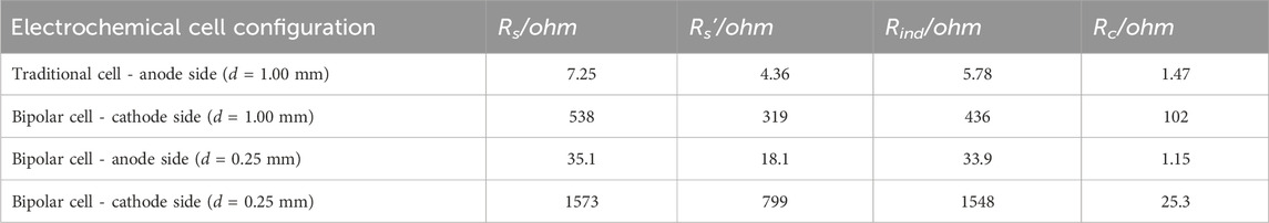
Table 1. Experimental series resistances for single (Rs) and connected (Rs’) nickel electrodes and calculated individual (Rind) and collective (Rc) resistances or the various electrochemical cell configurations.
Now we are in position to evaluate the coupling strength for the bipolar cell. The total cell resistance is
Similar calculation was also performed with the bipolar cell system with the 0.25 mm diameter electrodes. Table 1 and Table 2 show the measured solution resistances and the coupling strength; the charge transfer resistance was
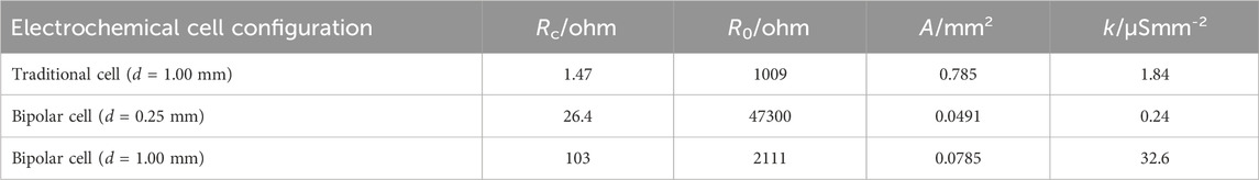
Table 2. Calculation for experimental coupling strength for the various cell types.
Figure 7A summarizes the findings related to the calculated electrical coupling strengths: very strong coupling was observed with the bipolar cell using d = 1 mm, and weak couplings with the bipolar cell using d = 0.25 mm and the traditional cell with d = 1 mm. Figure 7B shows the calculated extent of synchronization for the three different cells. To characterize the extent of synchrony, an index (
where i is the complex unit, the summation is taken over the measured time series, < > is the time average. When
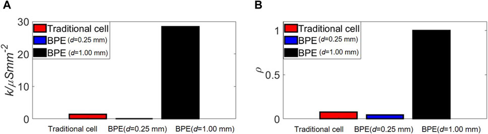
Figure 7. Coupling strength (A) and synchronization index (B) for the various cell types.
4 Conclusion
We have shown that in a bipolar cell strong coupling effects induced synchronization of electrochemical oscillators. In the traditional configuration with nickel electrodissolution in 3.00 M H2SO4 the ohmic potential drop is very small (few mV), and an external resistance is required to observe oscillations, and there is no synchronization. With the bipolar cell studied here, hydrogen reduction on the cathode could destabilize the stationary behavior on the anode with its impact on the total cell resistance; furthermore, the large ohmic drops on the cathode side (due to the presence of low, 0.01 M concentration of H2SO4) resulted in synchronization of the electrode potential oscillations. By analysis of an equivalent circuit, we were able to experimentally characterize this coupling strength and show that with smaller wires (0.25 mm diameter instead of 1.00 mm) the coupling strength can be decreased due to the increased charge transfer resistance of hydrogen ion reduction.
The bipolar cell provides a novel route to investigate coupling of electrochemical oscillators using electrode arrays. Previously, with traditional cells, the coupling was either through potential drops in the electrolyte (Mukouyama et al., 1996; Jia and Kiss, 2012; Jia and Kiss, 2017), added external (collective (Kiss et al., 1999) or cross (Wickramasinghe and Kiss, 2013)) resistance, external feedback (Nagao et al., 2016), or through a common cathode (Hankins et al., 2017; Hankins et al., 2019). With the bipolar electrode the coupling is through a potential drop in the electrolyte, and thus the synchronization patterns are similar to those found with coupling through external resistance interface (Kiss et al., 1999; Kiss et al., 2006) and potential drop through the electrolyte in microfluidic flow cells (Jia and Kiss, 2012). With microfluidic flow cells, the coupling strength could be controlled with the placement of the working electrodes with respect to the reservoir where the reference/counter electrode was positioned (Jia and Kiss, 2012; Jia and Kiss, 2017). With the bipolar electrode, the nonlinear process took place on the anode side, and the coupling on the cathode side of the bipolar electrode was dominant. Therefore, the traditional roles of the electrolyte–providing chemical environment for the nonlinear charge transfer process and an electrical environment to facilitate (long-range) migration current coupling can be separated. This could open ways to versatile cell design where coupling effects can be studied without large changes in the local nonlinear dynamics. The versatility of the bipolar design thus allows changing electrolyte concentration and tuning the local dynamics and coupling independently. With other electrochemical systems (e.g., H2O2 reduction (Okada et al., 2021)), it could also be possible to study nonlinear cathodic systems and couple them on the anode side of the bipolar electrode. Exploring the interactions between the cathodes and the anodes could also find applications in fuel cells designs where the anodic electrode potential oscillations were shown to affect electrode potential variations of the cathode (Nogueira et al., 2019).
In the present study we utilized advanced electrochemical instrumentation with potentiostat and chronopotentiometry, which required direct connection to the bipolar electrodes. However, bipolar cell would need only a potential source (i.e., no potentiostat is needed) and the electrode array potential oscillations on the anode side could be recorded with electrogenerated luminescence on the cathode side (Richter, 2004). This could facilitate studies of synchronization patterns with thousands of electrodes (Chow et al., 2009) that would not be possible with the classical multi-electrode array technique. Such large bipolar electrode array could be constructed with simply embedding many wires in the epoxy, however, the coupling topology for such arrays should be carefully investigated. Coupling could help better design multielectrode detectors where coupling strength could be engineered; for sensor applications electrical crosstalk could be minimized between the electrodes but for in situ information processing using bipolar electrodes (Zhan and Crooks, 2003) the coupling could be leveraged as an additional activating factor to improve logic gate operations.
Data availability statement
The raw data supporting the conclusion of this article will be made available by the authors, without undue reservation.
Author contributions
JT: Formal Analysis, Investigation, Methodology, Writing–original draft, Writing–review and editing. IK: Conceptualization, Formal Analysis, Investigation, Methodology, Writing–original draft, Writing–review and editing.
Funding
The author(s) declare financial support was received for the research, authorship, and/or publication of this article. This material is based upon work supported by the National Science Foundation under Grant No CHE-1900011.
Conflict of interest
The authors declare that the research was conducted in the absence of any commercial or financial relationships that could be construed as a potential conflict of interest.
The author(s) declared that they were an editorial board member of Frontiers, at the time of submission. This had no impact on the peer review process and the final decision.
Publisher’s note
All claims expressed in this article are solely those of the authors and do not necessarily represent those of their affiliated organizations, or those of the publisher, the editors and the reviewers. Any product that may be evaluated in this article, or claim that may be made by its manufacturer, is not guaranteed or endorsed by the publisher.
References
Amatore, C., Da Mota, N., Lemmer, C., Pebay, C., Sella, C., and Thouin, L. (2008). Theory and experiments of transport at channel microband electrodes under laminar flows. 2. Electrochemical regimes at double microband assemblies under steady state. Anal. Chem. 80 (24), 9483–9490. doi:10.1021/ac801605v
Chow, K.-F., Mavre, F., Crooks, J. A., Chang, B.-Y., and Crooks, R. M. (2009). A large-scale, wireless electrochemical bipolar electrode microarray. J. Am. Chem. Soc. 131 (24), 8364–8365. doi:10.1021/ja902683f
Crooks, R. M. (2016). Principles of bipolar electrochemistry. ChemElectroChem 3 (3), 357–359. doi:10.1002/celc.201500549
Cruz, J. M., Rivera, M., and Parmananda, P. (2007). Experimental observation of different types of chaotic synchronization in an electrochemical cell. Phys. Rev. E. 75 (3), 035201. doi:10.1103/physreve.75.035201
de Poulpiquet, A., Sojic, N., Bouffier, L., Kuhn, A., and Zigah, D. (2023). Wireless electronic light emission: an introduction to bipolar electrochemistry. J. Chem. Educ. 100 (2), 767–773. doi:10.1021/acs.jchemed.2c00573
Duval, J., Kleijn, J. M., and van Leeuwen, H. P. (2001). Bipolar electrode behaviour of the aluminium surface in a lateral electric field. J. Electroanal. Chem. 505 (1), 1–11. doi:10.1016/s0022-0728(01)00461-2
Ferrari, M. L., and Massardo, A. F. (2013). Cathode–anode side interaction in SOFC hybrid systems. Appl. Energy 105, 369–379. doi:10.1016/j.apenergy.2013.01.029
Fosdick, S. E., Knust, K. N., Scida, K., and Crooks, R. M. (2013). Bipolar electrochemistry. Angew. Chem. Int. Ed. 52 (40), 10438–10456. doi:10.1002/anie.201300947
Haim, D., Lev, O., Pismen, L., and Sheintuch, M. (1992). Modeling periodic and chaotic dynamics in anodic nickel dissolution. J. Phys. Chem. 96 (6), 2676–2681. doi:10.1021/j100185a051
Hankins, M. J., Gáspár, V., and Kiss, I. Z. (2019). Abrupt and gradual onset of synchronized oscillations due to dynamical quorum sensing in the single-cathode multi-anode nickel electrodissolution system. Chaos (Woodbury, N.Y.) 29 (3), 033114. doi:10.1063/1.5087405
Hankins, M. J., Wickramasinghe, M., and Kiss, I. Z. (2017). Synchronization of current oscillations in a dual-anode dissolution reaction in the presence of a common cathode electrode. Electrochimica Acta 252, 76–83. doi:10.1016/j.electacta.2017.08.153
Hudson, J. L., and Tsotsis, T. T. (1994). Electrochemical reaction dynamics: a review. Chem. Eng. Sci. 49 (10), 1493–1572. doi:10.1016/0009-2509(94)85063-1
Jia, Y., and Kiss, I. Z. (2012). Spontaneously synchronized electrochemical micro-oscillators with nickel electrodissolution. J. Phys. Chem. C 116 (36), 19290–19299. doi:10.1021/jp3047278
Jia, Y., and Kiss, I. Z. (2017). Decoding network structure in on-chip integrated flow cells with synchronization of electrochemical oscillators. Sci. Rep. 7, 46027. doi:10.1038/srep46027
Karantonis, A., Pagitsas, M., Miyakita, Y., and Nakabayashi, S. (2004). In-phase, anti-phase and fractured synchrony in ring networks of coupled relaxation electrochemical oscillators. J. Phys. Chem. B 108 (18), 5836–5846. doi:10.1021/jp049767u
Kiss, I. Z., Kazsu, Z., and Gáspár, V. (2006). Tracking unstable steady states and periodic orbits of oscillatory and chaotic electrochemical systems using delayed feedback control. Chaos (Woodbury, N.Y.) 16 (3), 033109. doi:10.1063/1.2219702
Kiss, I. Z., Wang, W., and Hudson, J. L. (1999). Experiments on arrays of globally coupled periodic electrochemical oscillators. J. Phys. Chem. B 103 (51), 11433–11444. doi:10.1021/jp992471h
Kiss, I. Z., Zhai, Y., and Hudson, J. L. (2002). Emerging coherence in a population of chemical oscillators. Science. 296 (5573), 1676–1678. doi:10.1126/science.1070757
Kiss, I. Z., Zhai, Y., and Hudson, J. L. (2005). Predicting mutual entrainment of oscillators with experiment-based phase models. Phys. Rev. Lett. 94 (24), 248301. doi:10.1103/physrevlett.94.248301
Koefoed, L., Pedersen, S. U., and Daasbjerg, K. (2017). Bipolar electrochemistry—a wireless approach for electrode reactions. Curr. Opin. Electrochem. 2 (1), 13–17. doi:10.1016/j.coelec.2017.02.001
Koper, M. T. M. (1998). Non-linear phenomena in electrochemical systems. J. Chem. Soc. Faraday Trans. 94, 1369–1378. doi:10.1039/a708897c
Krischer, K. (2002). Nonlinear dynamics in electrochemical systems. Weinheim, Germany: Wiley-VCH Verlag.
Liu, Y., and Kiss, I. Z. (2023). Nonlinear dynamics of coupled nickel electrodissolution with hydrogen ion reduction with bipolar electrodes. J. Electrochem. Soc. 170, 113505. doi:10.1149/1945-7111/ad0baf
Loget, G., and Kuhn, A. (2011). Shaping and exploring the micro- and nanoworld using bipolar electrochemistry. Anal. Bioanal. Chem. 400 (6), 1691–1704. doi:10.1007/s00216-011-4862-1
Loget, G., Zigah, D., Bouffier, L., Sojic, N., and Kuhn, A. (2013). Bipolar electrochemistry: from materials science to motion and beyond. Accounts Chem. Res. 46 (11), 2513–2523. doi:10.1021/ar400039k
Mavre, F., Anand, R. K., Laws, D. R., Chow, K.-F., Chang, B.-Y., Crooks, J. A., et al. (2010). Bipolar electrodes: a useful tool for concentration, separation, and detection of analytes in microelectrochemical systems. Anal. Chem. 82, 8766–8774. doi:10.1021/ac101262v
Morse, G. E., Castrucci, J. S., Helander, M. G., Lu, Z.-H., and Bender, T. P. (2011). Phthalimido-boronsubphthalocyanines: new derivatives of boronsubphthalocyanine with bipolar electrochemistry and functionality in OLEDs. ACS Appl. Mater. Interfaces 3 (9), 3538–3544. doi:10.1021/am200758w
Mukouyama, Y., Hommura, H., Matsuda, T., Yae, S., and Nakato, Y. (1996). Synchronous current oscillations in electrochemical reduction reactions on two platinum electrodes in sulfuric acid solution containing hydrogen peroxide. Chem. Lett. 25 (6), 463–464. doi:10.1246/cl.1996.463
Nagao, R., Zou, W., Kurths, J., and Kiss, I. Z. (2016). Restoring oscillatory behavior from amplitude death with anti-phase synchronization patterns in networks of electrochemical oscillations. Chaos (Woodbury, N.Y.) 26 (9), 094808. doi:10.1063/1.4954040
Nogueira, J. A., Krischer, K., and Varela, H. (2019). Coupled dynamics of anode and cathode in proton-exchange membrane fuel cells. ChemPhysChem 20 (22), 3081–3088. doi:10.1002/cphc.201900531
Ocampo-Espindola, J. L., Bick, C., and Kiss, I. Z. (2019). Weak chimeras in modular electrochemical oscillator networks. Front. Appl. Math. Stat. 5 (38). doi:10.3389/fams.2019.00038
Okada, H., Mizuochi, R., Sakurada, Y., Nakanishi, S., and Mukouyama, Y. (2021). Electrochemical oscillations (named oscillations H and K) during H2O2 reduction on Pt electrodes induced by a local pH increase at the electrode surface. J. Electrochem. Soc. 168 (7), 076512. doi:10.1149/1945-7111/ac14d8
Orlik, M. (2012a). “Self-organization in electrochemical systems I: general principles of self-organization,” in Temporal instabilities (Berlin, Chin: Springer-Verlag).
Orlik, M. (2012b). Self-organization in electrochemical systems II: spatiotemporal patterns and control of chaos. Berlin, Germany: Springer-Verlag.
Pikovsky, A., Rosenblum, M., and Kurths, J. (2003). Synchronization: a universal concept in nonlinear sciences. Cambridge, United Kingdom: Cambridge University Press.
Richter, M. M. (2004). Electrochemiluminescence (ECL). Chem. Rev. 104 (6), 3003–3036. doi:10.1021/cr020373d
Schelter, B., Winterhalder, M., Dahlhaus, R., Kurths, J., and Timmer, J. (2006). Partial phase synchronization for multivariate synchronizing systems. Phys. Rev. Lett. 96 (20), 208103. doi:10.1103/physrevlett.96.208103
Sentic, M., Arbault, S., Bouffier, L., Manojlovic, D., Kuhn, A., and Sojic, N. (2015). 3D electrogenerated chemiluminescence: from surface-confined reactions to bulk emission. Chem. Sci. 6 (8), 4433–4437. doi:10.1039/c5sc01530h
Varela, H., Beta, C., Bonnefont, A., and Krischer, K. (2005). A hierarchy of global coupling induced cluster patterns during the oscillatory H2-electrooxidation reaction on a Pt ring-electrode. Phys. Chem. Chem. Phys. 7 (12), 2429–2439. doi:10.1039/b502027a
Wang, W., Kiss, I. Z., and Hudson, J. (2000). Experiments on arrays of globally coupled chaotic electrochemical oscillators: synchronization and clustering. Chaos Interdiscip. J. Nonlinear Sci. 10 (1), 248–256. doi:10.1063/1.166470
Wang, W., Kiss, I. Z., and Hudson, J. L. (2002). Synchronization and clustering of arrays of electrochemical oscillators with global feedback. Ind. Eng. Chem. Res. 41 (3), 330–339. doi:10.1021/ie0100737
Wickramasinghe, M., and Kiss, I. Z. (2012). Synchronization of electrochemical oscillators engineering of chemical complexity. World Sci. Lect. Notes Complex Syst. 11, 215–236. doi:10.1142/9789814390460_0011
Wickramasinghe, M., and Kiss, I. Z. (2013). Spatially organized dynamical states in chemical oscillator networks: synchronization, dynamical differentiation, and chimera patterns. PLoS One 8 (11), e80586. doi:10.1371/journal.pone.0080586
Wickramasinghe, M., and Kiss, I. Z. (2016). Nonlinear behavior of nickel dissolution in sulfuric acid in a cathode-anode cell configuration: effect of cathode area. J. Electrochem. Soc. 163 (14), H1171–H1178. doi:10.1149/2.0471614jes
Keywords: synchronization, oscillations, electrochemistry, reaction kinetics, nonlinear dynamics
Citation: Tetteh JA and Kiss IZ (2024) Synchronization of two electrochemical oscillators in a closed bipolar cell. Front. Complex Syst. 2:1397573. doi: 10.3389/fcpxs.2024.1397573
Received: 07 March 2024; Accepted: 05 April 2024;
Published: 18 April 2024.
Edited by:
Istvan Lagzi, Budapest University of Technology and Economics, HungaryReviewed by:
Hisashi Hayashi, Japan Women’s University, JapanPrashant Gade, Rashtrasant Tukadoji Maharaj Nagpur University, India
Copyright © 2024 Tetteh and Kiss. This is an open-access article distributed under the terms of the Creative Commons Attribution License (CC BY). The use, distribution or reproduction in other forums is permitted, provided the original author(s) and the copyright owner(s) are credited and that the original publication in this journal is cited, in accordance with accepted academic practice. No use, distribution or reproduction is permitted which does not comply with these terms.
*Correspondence: István Z. Kiss, aXN0dmFuLmtpc3NAc2x1LmVkdQ==