 Jarne Van Mulders
 Sam Boeckx
 Jona Cappelle
 Liesbet Van der Perre
- Dramco, Waves: Core Research and Engineering (WaveCore), Department of Electrical Engineering (ESAT), KU Leuven, Ghent, Belgium
Internet of Things technology is named as a key ingredient in the evolution towards digitization of many applications and services. A deployment based on battery-powered remote Internet of Things (IoT) devices enables easy installation and operation, yet the autonomy of these devices poses a crucial challenge. A too short lifespan is undesirable from a functional, economical, and ecological point of view. This paper presents a unmanned aerial vehicle (UAV)-based approach to recharge remote Internet of Things (IoT) nodes. An in-depth study of the charging efficiency and optimization of key parameters, and measurements-based verification, is reported on. An actual corresponding design and implementation of the full UAV-based charging system and its proof-of-concept validation are presented. Finally, the sustainability of the proposed solution is discussed. The results presented in this paper hence confirm that the proposed UAV-based approach and design are functionally successful and efficient charging can be achieved, provided the constraints and challenges coming with the approach are adequately dealt with. Moreover, it comes with an overall reduction in ecological footprint for IoT applications relying on battery-powered nodes in need of medium energy and/or considerable lifetime expectation (5 years or more).
1 Introduction
1.1 Research context
The deployment of Internet of Things (IoT) systems and wireless sensor networks (WSNs) opens up an interesting potential for environmental monitoring, improving logistics efficiency, and diverse other applications (Salam, 2020). Many IoT devices thereto need to operate on a battery in a remote location. This causes a main challenge in the adoption of IoT technology: the nodes have a limited lifetime (Callebaut et al., 2024), which possibly incurs a high overhead in maintenance. Moreover, the ecological footprint may be considerable as non-rechargeable batteries are often selected because of their high energy density in terms of energy per unit volume and/or weight.
The conventional strategies to prolong the autonomy of IoT devices are: 1) select physically larger batteries, 2) equip the device with an energy harvesting solutions and a rechargeable battery (Shaikh et al., 2016; Shaikh and Zeadally, 2018), which increases the complexity, and 3) plan for service visits to replace or recharge batteries. It should be noted that these three options all come at a cost, while they may not be a physically convenient option for all applications, for example, it may be cumbersome to reach IoT nodes on high positions.
We here present an unmanned aerial vehicle (UAV)-based charging solution, illustrated in Figure 1, as an alternative for extending the lifetime of IoT devices.
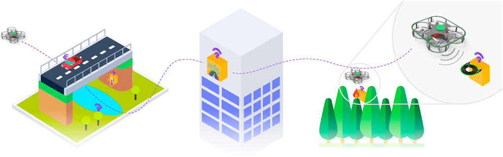
Figure 1. System overview: a UAV approach to extend the lifetime of IoT devices in different use-cases.
1.2 Prior art and related work
The support of UAVs in IoT systems has been proposed mostly to provide network functionality (Hentati and Fourati, 2020), e.g., for time-varying and vehicle networks (Cui et al., 2022; Hemmati et al., 2023) or to perform remote monitoring tasks by themselves (Vom Bögel et al., 2020; Asadzadeh et al., 2022). In the context of charging, the UAV is mostly considered as the device to be (wirelessly) charged (Rohan et al., 2019). When UAVs are considered in the role of charge provider (Cetinkaya et al., 2020; Ojha et al., 2023) it most often concerns RF-based charging or RF energy harvesting (Yao et al., 2019), whether or not combined with communication, e.g., in simultaneous wireless information and power transfer (SWIPT), which is different from the here considered coupled wireless power transfer.
While many works have studied the ground-to-UAV channel for wireless communication purposes over at least several meters (e; g., (Jiang et al., 2019), these models do not apply to the approach discussed in this paper. In this work, we envision that the UAV approaches the IoT device closely–typically to within 10 cm. The conceptual idea of a UAV to recharge an IoT device at its location ‘on the spot’ or replace its battery has been introduced in (Van Mulders et al., 2023), where an efficiency comparison of a coupled wireless power transfer versus RF-based charging is also presented. By calculating the energy efficiency for this method, we demonstrate that the ‘UAV flying in’ to charge the device provides an effective option to extend the autonomy of devices. In this paper we investigate the question: To which extent can the charging by the UAV nearing the device result in autonomy improvements and create an efficient solution? We thereby extend the analysis beyond efficiency of the energy transfer, and also assess the self-impact of the UAV and the IoT node to get a more complete picture of the actual environmental impact. By extending the autonomy, we inherently avoid generating new devices or having to replace the battery. At the same time, this approach enables new possibilities for devices with a higher energy consumption in remote areas, where human intervention comes with significant overhead. We here consider the scenario where the UAV in a dedicated mission charges one IoT device. We note that further efficiency gains could be achieved when deploying multiple UAVs and optimizing routes, as for the communications case discussed in (Khelifi et al., 2018).
1.3 Paper contributions
The focus of this paper is on an in-situ charging solution for IoT devices accomplished by a UAV that flies close enough to enable coupled wireless power transfer. The latter can achieve a transfer efficiency on the link that is order of magnitudes higher than RF-waves based transfer. The main contributions of our study are: We detail the charging concept, identify the main additional technological challenges that come into play when targeting a UAV-based charging solution, and propose a design to optimize specifically the coupled wireless power transfer link. We thereto perform an analytical study of the coupling factor, and focus on the magnetic resonance coupling approach that we identify as most adequate for the problem at hand. We propose a proof of concept prototype, that is compliant with the 250 g weight limit for unlicensed operation of the UAV in Europe, according to the regulatory framework by the European Union Aviation Safety Agency (EASA) (EASA, 2015), and that is able to transfer power in the order of Watts to the IoT device. The experimental validation of the UAV-based coupled wireless charging concept is presented. We further provide a critical view of the system implementation by assessing the sustainability aspects.
The remainder of this paper is structured as follows. The next section elaborates on the charging concept and architecture, and the analytical study of the wireless power transfer. The design of the UAV, capable of wireless power transfer (WPT) is presented in section 4, and the experimental validation in section 5. The analysis of sustainability aspects follows in section 6, and the conclusions are formulated in section 7.
2 UAV based charging approach and high-level architecture
The concept of UAV-based charging as depicted in Figure 1, shows that the UAV is expected to fly to the depleted node and recharge the internal battery. In an autonomous implementation, a system to align the UAV and the IoT node is required. While in conventional systems charging connectors are the preferred solution due to high power transfer levels and efficiency, they are susceptible to corrosion, moisture ingress, and the tolerance for alignment errors is quite limited. Selecting a wireless power transfer solution instead, can isolate the electronics from ambient influences and increase the alignment margins, and is therefore considered the most suitable solution for the charging approach handled in this paper. The alignment of the UAV towards the IoT device itself is not addressed in this study. We direct the reader to (Van Mulders, Leenders, Callebaut, De Strycker & Van der Perre, 2022; Ojha et al., 2023) for an overview of both coarse and precise positioning as well as alignment capabilities.
The required alignment accuracy depends closely on the chosen WPT technology. A comprehensive analysis of potential WPT solutions is beyond the scope of this manuscript, and the reader is referred to (Van Mulders et al., 2022) for more information. We can briefly summarize that due to limitations in power density, a coupled system is preferred over an uncoupled system (Van Mulders et al., 2023). Additionally, a WPT system based on coupled capacitive plates is generally only feasible for bridging a few millimeters, making it unsuitable for UAV implementations. In contrast, WPT using fluctuating magnetic fields can cover ranges of upto a few centimeters and is more resilient against misalignments. Therefore, the latter is considered the most viable solution in this context.
Consequently, the system studied in this paper is limited to a UAV with a WPT transmitter, a receiver and transmitter coil, a WPT receiver, and the IoT node itself. This high-level architecture is presented in Figure 2. The WPT transmitter and WPT receiver, or power transmitting unit (PTU) and power receiving unit (PRU) respectively, can communicate wirelessly with each other and optionally send data to a ‘data logger’ for debug and design purposes. For experiments, the ‘flight controller’ is utilized to send flight commands to the UAV. Lastly, the ‘gateway’ in the WSN acts as the low-power wide-area network (LPWAN)-to-internet bridge, centralizing and storing the IoT data to, e.g., a database. The gateway and flight controller are not further discussed in this paper, as this work focuses on the UAV-based charging concept.
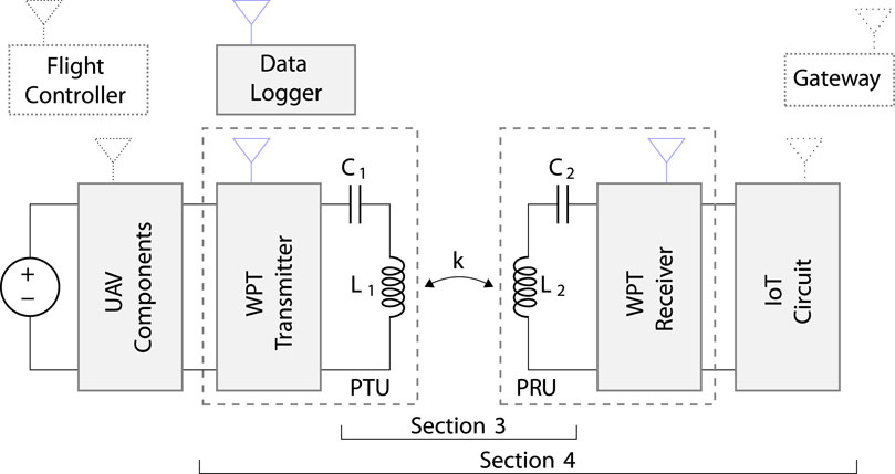
Figure 2. Focused structure of the contributions of this paper. The data logger, WPT transmitter, and receiver use BLE to communicate. The selected BLE SoC can also be employed as application MCU for the IoT circuit.
As mentioned in Section 1, the feasibility of the system will be demonstrated with a UAV that has weight constraints. Hence, we consider applications for which the energy requirements of the IoT device are relatively small. A 60 mAh lithium titanate (LTO) cell (HuaHui, 2023) is selected to power the IoT’s onboard sensors, actuators, and LPWAN modem. Assuming that the UAV hovers during the charging cycle, it is recommended to limit the charge time. This clarifies the choice of an LTO cell, which can be recharged at rates of up to 10 C (6 min), whereas many other cell technologies are typically rechargeable around 1 C (1 h).
The remainder of this section focuses on the wireless power transfer technology. As motivated above, WPT based on fluctuating magnetic fields is the preferred solution in this context. The achievable power transfer levels and efficiencies depend on the design of the coils and their relative position. The coupling factor between the transmit and receive coil is a central determining factor, including its sensitivity to alignment errors.
Two technologies, namely, inductive power transfer (IPT) and magnetic resonance coupling (MRC), provide energy transmission via magnetic fields. The most suitable solution depends on the feasible coupling factors between the transmit and receive coils. In 2.1, an analytical study is performed to estimate the coupling factors.
2.1 Coupling factor analytical study
To optimize the coil selection and parameter settings, an analytical study is performed to predict the coupling factor based on simplified coil models and MATLAB® simulations. The resulting estimated coupling factors can provide initial insight into the feasibility of the system and time-consuming finite element (FEM) analyses can be avoided in the first place. In Section 3, advanced simulation and measurement techniques are applied as a verification and to obtain more accurate coupling factor results.
This analysis is confined to a set of assumptions pertaining to the specific parameters of the transmit and receive coils.
• The dimensions of the transmit coil are constrained by the size of the UAV model, which measure 146 × 164 mm.
• Given the spatial constraints of the UAV frame, it is feasible to incorporate two windings on the transmit side, without altering the flight characteristics of the UAV.
• The quantity of windings on the receiver side may exceed that on the transmitter side. However, an excessive number of windings can impact the quality factor due to increased equivalent resistance. The quality factor depends on the frequency and affects the link performance, as discussed further in Section 2.2. Moreover higher self-inductance values potentially result in more tuning instabilities due to reduced tuning capacitor values.
• Given the assumption that the UAV hovers during the charging process, it is crucial to ensure that the receiver coil does not obstruct the airflow completely.
2.1.1 Mathematical model for coupling coefficient estimations
The analytical models, based on formulas from (Rosa, 1908; Shuo Liu and Lai, 2019), which we implemented in MATLAB® for simulation purposes, provide a baseline indication of the coupling between two coils. To make the simulation less time-consuming than FEM analyses, spiral coils are approximated by concentric circles.
The coupling coefficient k between two coils is calculated as follows
with M12 the mutual inductance between the two coils, L1 the self-inductance of the primary coil and L2 the self-inductance of the secondary coil.
To calculate the self-inductance L of a coil, the self-inductance Li of every winding needs to be calculated as well as the mutual inductance Mij between every possible winding pair. The sum off these, results in the total self-inductance of the coil. For a coil with two windings i and j for instance, the self-inductance results in L = Li + Lj + Mij + Mji. Note that Mij and Mji are equal.
Eq. 2 is used to calculate the self-inductance of every winding (Rosa, 1908).
with μ the magnetic permeability, equal to μ0μr where μ0 is the magnetic permeability in vacuum with a value of 4π ⋅ 10–7 H/m and μr is the relative magnetic permeability of the medium which is air in this case, so, μr is here equal to one. ri is the radius of the winding and a is the radius of the wire. The term Y accounts for the skin effect.
with ω = 2πf the angular frequency and σ the specific conductivity of the wire. Y will be zero if the current only flows on the surface of the wire and one if the current is distributed uniformly over the cross section of the wire.
Eq. 4 is used to calculate the mutual inductance between a pair of windings (Shuo Liu and Lai, 2019)
with
and ri the radius of one winding, rj the radius of another winding, d the vertical distance between the centers of the wires and K(s) and E(s) the complete elliptic integrals of the first and second kind respectively
and
In this case the vertical distance d = 0, seeing that the coils exist of only one layer of windings. The windings are all in the same plane.
The mutual inductance M12 between two coils can be calculated in the same way. Eq. 4 is used again yet ri and rj are radii of windings of different coils and d is now the vertical distance between the two coils. This is calculated for every possible winding pair and summed to get the overall mutual inductance. For two coils with two windings for instance, the mutual inductance results in M12 = M1i2i + M1j2j + M1i2j + M1j2i.
Knowing L1, L2 and M12 makes it possible to calculate k using (1).
2.1.2 Calculating coupling factors for the considered use case
The MATLAB®-based study is conducted at a frequency of 6.78 MHz, a license-free industrial, scientific and medical (ISM) band. In fact, the self-inductance and coupling factors are mainly influenced by the coil specifications and the distance between the transmitter and receiver, with a lesser impact from the frequency. In contrast, the skin effect, depending on the frequency, affects the equivalent series resistance of the coil and consequently also the quality factor. This latter is important for the link efficiency, discussed in Section 3.2. The skin effect has a minor impact on self-inductance compared to the impact on the quality factor. Consider, for instance, two spiral coils with a diameter of 100 mm, a wire radius of 1 mm, 5 windings and a distance of 100 mm between them. The coupling factor for 100 kHz and 6.78 MHz estimated with the above equations taking the skin effect into account, results in 0.030561714 and 0.030561708 respectively. This confirms our expectations, and thus, the further results and insights of this section are applicable for the whole frequency band ≤10 MHz.
The proposed model from Section 2.1.1, considering spiral coils, is used to investigate the impact of different dimensions and geometries of coils on the UAV on the coupling coefficient between the transmit and receive coils. For the transmit coil, the UAV leaves no room for adapting the coil diameter or number of windings; a fixed coil configuration is used at the transmit side. It should be noted that the shape of the transmit coil, on the UAV, more closely approximates a rectangular form compared to a spiral-shaped coil. To better match the dimensions of the UAV, the average of the x and y dimensions of the UAV model is considered as the radius of the outer concentric circle in MATLAB®. The distance between the concentric circles is assumed to be 1 mm. For the considered design, this results in radii 74.5 and 76.5 mm, knowing that there is space for two windings on the transmitter coil. According to the MATLAB® model, this approximation of the transmit coil has a self-inductance of 1.587 µH. For the receive coil at the IoT side there is more design freedom in order to optimize the coupling; various configurations are compared in the study.
In the next paragraphs we present the results of the analytical study of the coupling factor and in particular the impact of coil-to-coil distance (the vertical distance ΔZ between the coils), the different receive coil diameters and the lateral and angular misalignments.
2.1.2.1 Impact of the coil-to-coil distance
In situations with little or no wind, the coil-to-coil and lateral distances between transmit and receive coil will be the main factors affecting the coupling coefficient. A first assessment is performed, regarding coil-to-coil distance for four different dimensions of receive coils, each with four turns. The outer dimensions of the considered coils are 75 mm, 100 mm, 125 mm, and 150 mm. The impact of the coil-to-coil distance between transmit and receive coil, all assuming lateral alignment, is shown in Figure 3, and presents the impact on the coupling coefficients and the receiver coil self-inductance.
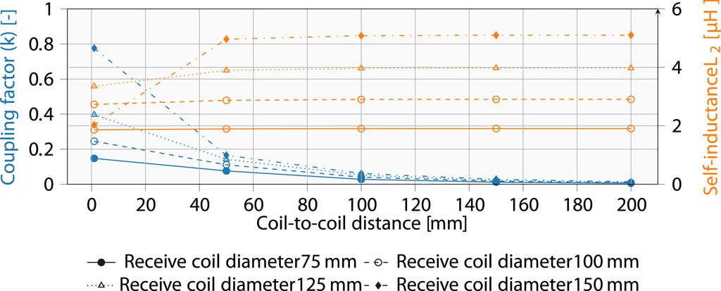
Figure 3. Variation of the coupling coefficient and receiver coil self-inductance relative to the coil-to-coil distance. We note that variations in coil-to-coil distance induce also changes in the self-inductance of the transmitter coil, especially at short distances (i.e., for high coupling).
Upon reviewing Figure 3, it is observed that the coupling coefficient is the highest for the largest receive coil. This is as expected seeing that these dimensions better correspond to the dimensions of the transmit coil. Higher coupling factors, in general, allow for better efficiencies. However, the better the coupling, the higher the impact on the self-inductance. Due to the dynamic nature of a hovering UAV, variations in coil distances are likely over time. This could result in detuning of the coils and thus a drop in the power transfer efficiency, as further explained in Section 2.3.
For the remainder of this manuscript, a receiver coil with a 100 mm diameter is preferred over the 75 mm coil due to the slightly higher achievable coupling factors. Figure 3 demonstrate that the self-inductance of the 100 mm receiver coil undergoes minimal changes and at the same time ensures adequate coupling upto 100 mm.
Another trade-off to consider is the size of the IoT node and consequently, the size of the receive coil. Since the results indicate that sufficient coupling can be achieved with all proposed receiving coils, the smaller 100 mm coil is selected to ensure practical feasibility.
2.1.2.2 Coil-to-coil and lateral misalignments
Figure 4A shows the impact of both coil-to-coil and lateral misalignments. This clearly indicates that the issues related to relative positioning can mutually amplify. For UAV-based charging, this implies that the transfer range between the node and drone is limited, and lateral misalignments must be kept within a few centimeters.
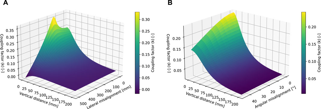
Figure 4. Coupling factor variations for different misalignments and with a receiver coil of 100 mm. (A) Increasing coil-to-coil distances and lateral misalignments. (B) Increasing coil-to-coil distances and angular misalignments.
2.1.2.3 Number of coil windings
The impact of the number of coil windings on the coupling factor was also assessed. The results, listed in Table 1, show that the impact on the coupling factor is rather low (≤10%). The number of windings has an impact on the self-inductance of the coil. The quantity can be chosen based on the desired self-inductance value to facilitate tuning to the working frequency, for instance, 6.78 MHz.
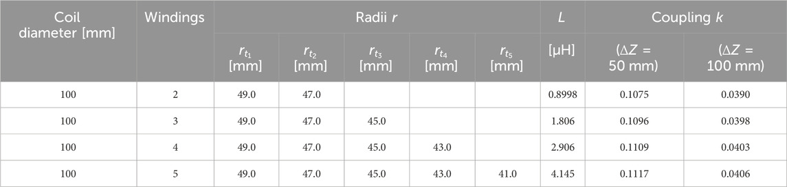
Table 1. Coupling between transmit and receive coil considering different number of windings at coil-to-coil distances ΔZ of 50 mm and 100 mm.
2.1.2.4 Impact of angular misalignment
When the two coils are not perfectly parallel the coupling factor will be influenced, this is depicted in Figure 4B. It is clear that for the UAV-based charging, a perfect angular positioning can not be guaranteed in case of wind for instance. This may cause a certain loss in actual power transfer. However, we may assume the angular misalignment error in general to be relatively small, typically ≤10°. Hence, this will not significantly affect the coupling coefficient.
2.2 MRC system introduction and mathematics
Section 2.1 demonstrates that the coupling factors are expected around or lower than 0.1, making MRC the most suitable WPT technology for these loosely coupled coils. This technology exhibits greater tolerance to changes in the coupling factor compared to other WPT solutions while maintaining a sufficiently high power density over the link (Van Mulders, Delabie, Lecluyse, Buyle, Callebaut, Van der Perre & De Strycker, 2022). The MRC architecture was already shown in Figure 2, whereby the WPT transmitter can be simplified as an alternating current (AC) source with amplitude VS to drive the primary LC tank, and the WPT receiver gets its energy from the secondary LC tank and can be represented by an equivalent AC load RL. The AC source is located at the UAV, while RL represents the charging circuit and energy buffer of the IoT node. A more comprehensive discussion concerning the design components can be found in Section 4. The section focuses on the MRC system and related implementation choices.
In MRC both transmitter and receiver are perfectly tuned to the resonance frequency as given in Eq. 6. The ISM frequency 6.78 MHz is selected as carrier. This relatively high frequency, compared to the often applied 100 kHz (in Qi (Wireless Power Consortium, 2021)), ensures the use of lower cost printed circuit board (PCB) coils, lower heating problems or eddy currents, and higher quality factors between transmit and receive coils. Given the thin PCB traces, typically 35 µm thick, the skin effect can be disregarded and no expensive Litz wire is required.
Series-series resonance is the preferred tuning configuration, particularly due to its higher efficiency compared with other options. In (Imura and Imura, 2020) (Ch. 5) provides a comprehensive elaboration on the fundamental tuning types: N-N, N-S, S-N, S-S, and S-P, where N, S, and P represent non-resonant, series resonant, and parallel resonant transceiver tank, respectively. This study reveals that the highest efficiencies can be achieved with S-S and S-P configurations. S-S is equivalent to a current source at the secondary, while S-P is equivalent to a voltage source at the secondary. In both circuit types, C1 is responsible for facilitating high power transfer, and C2 is instrumental in achieving the required efficiency levels. For the remainder of this paper, we assume the S-S configuration as depicted in Figure 2.
Our objective is to determine the link efficiency related to the power consumed in the load RL. Obviously, having an infinitely small or an infinitely large load, will results in zero efficiency. Hence, there exists an optimal point RL,opt. Furthermore, it can be advantageous to estimate the input voltage VS based on the required load power PL. To derive the expression for the link efficiency and determine the optimal parameters, the circuit diagram depicted in Figure 2 can be substituted with the equivalent T-model network, and Kirchhoff’s voltage law can be applied. The non-ideal coils L1 and L2 incorporate series resistances R1 and R2, respectively. The internal series resistor from the power supply VS is represented by RS.
The link efficiency determined by the power consumed in the load PL relative to the input power PS is given by Eq. 7.
with kmrc the coupling factor and the quality factor of transmitter and receiver circuit, QT and QR, as specified in Eq. 8.
The maximum MRC efficiency will occur for a specific value of RL and can be determined by taking the derivative of formula Eq. 7, as given in Eq. 9.
For a more detailed derivation, we direct the reader to (Baker and Sarpeshkar, 2007; Rindorf et al., 2008; Ahn and Hong, 2013; Van Mulders et al., 2022).
2.3 Concluding remarks regarding the MRC system design for UAV-based charging
The default procedure in the design of the MRC charging system would be to select transmitter and receiver coils and measure the self-inductance in open air. Consequently, the LC tanks are tuned to a certain frequency band by adding an appropriate series capacitor. Maximum transfer is guaranteed if LC tuning is optimal. However, Figure 3 shows that L1 and L2 relate to the vertical distance between the coils. Thus, positioning the coils in close proximity to each other can alter the inductance L1 and L2, potentially causing a mismatch between the tuning frequency and the designed operating frequency, thereby no longer satisfying Eq. 6. Hence, it is imperative to avoid excessive coupling as its occurrence will inevitably lead to a decline in efficiency. As Figure 3 shows, appropriate coil selection can avoid this.
3 WPT design for UAV-based charging
Before proceeding with the implementation, we considered it important to assess the expected efficiency levels with a higher confidence level through more detailed simulations and calculations. This chapter is dedicated to a thorough exploration of the essential building blocks required for the WPT system, including the selection of the coils, and the determination of the maximum achievable link efficiency.
3.1 Coil design
To pursue a more in-depth analysis of the proposed system, the coils need to be defined initially. The transmitter coil shape must align with the UAV model presented in Figure 5 and has dimension 146 × 164 mm. From the initial analysis in Section 2.1, it has been determined that a receiver coil with four windings and dimensions of 100 × 100 mm is a suitable choice. It could pick up the alternating magnetic field energy when the UAV is approaching a depleted IoT device as specified in Figure 3. Authors in (Hackl et al., 2008) describe how to measure the coupling coefficient kmrc via different approaches and comment on the parasitic capacitive coupling between closely coupled coils. Since the distance between transmitter and receiver coils is sufficiently high in the application at hand, the capacitive coupling can be ignored (Jeon and Seo, 2019). The electrical coupling is negligible compared to the magnetic coupling.
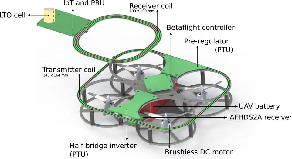
Figure 5. Render of the full system for the proposed approach to charge IoT nodes autonomously. The UAV battery delivers DC power to the Betaflight controller and pre-regulator. The latter forwards power to the half-bridge inverter and is further connected to the transmission coil. The receiver coil receives the alternating magnetic field and charges the IoT battery.
A FEM analysis is presented in Section 3.1.1, providing the coupling factor variation as a result of vertical and lateral misalignment. These simulations are conducted using only coils in free space, without considering any neighboring materials. In Section 3.1.2, the results from the FEM-based assessment are validated with actual measurements, and the impact of additional UAV elements in the neighborhood of the transmit coil on the coupling factor is evaluated. This is accomplished using the two-port method detailed in (Jeon and Seo, 2019). Section 3.1.3 validates the tuning quality through a one-port measurement.
3.1.1 FEM simulation to define variations in coupling factor
In the Ansys Maxwell finite element software tool (ANSYS, Inc, 2023), the two coil models were created to investigate how coil parameters and, consequently, the coupling factor are influenced by different misalignments. The coils are modeled using an FR4 PCB substrate (2-layer coil) with a thickness of 0.6 mm. The FEM tool simulates the self-inductance L1, equivalent series resistance R1, the self-inductance L2, equivalent series resistance R2 and mutual inductance M12. Knowing that the frequency is 6.78 MHz, the coupling factor k and the quality factors Q1 and Q2 can be determined using Eqs 1, 8. Several results from the FEM analysis regarding the coupling factor are depicted in Table 2.
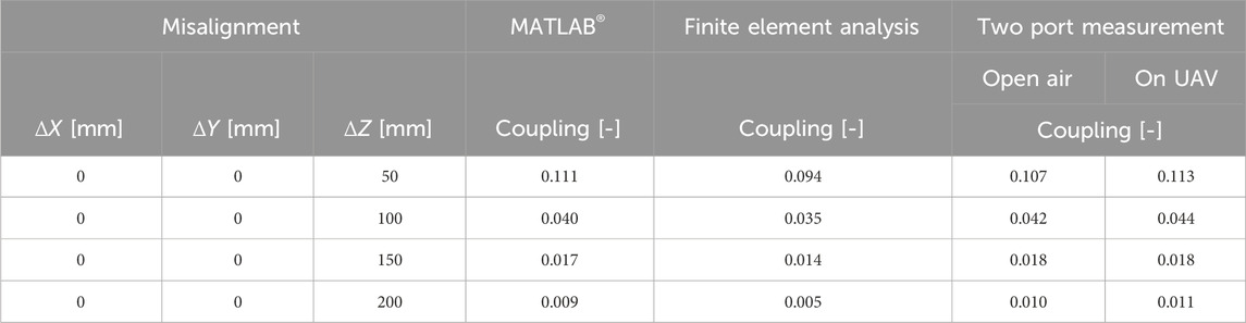
Table 2. Coupling factor k simulated and measured for different vertical misalignment distances.
3.1.2 Measurement-based validation of the computed coupling factors
The finite element simulations from Section 3.1.1 are verified by measuring the coupling factor between the coils with the characteristics as used in the simulations. Since modelling a UAV is rather complex, it is here preferred to measure the influence of the UAV components and materials on the coupling factor. As explained in (Jeon and Seo, 2019), the coupling factor can be determined via a two port measurement with a vector network analyzer (VNA). Before performing the measurements, the R&S VNA ZVL3 and a coaxial cable are calibrated with the Siglent F604FS 9 GHz SMA-Female calibration kit. The experimental configuration is similar to Figure 10, differing only in that solely the coils were interfaced with the VNA. Notably, the additional electronic components depicted in this figure are superfluous for the purpose of determining the coupling factor. Via Standard Commands for Programmable Instruments (SCPI), the VNA returns the [S] matrix which can be converted to the [Z] matrix (represented in Eq. 10) and ultimately the coupling factor.
The equation to convert the measurement data to kmrc is presented in Eq. 1 with L1, L2, and M12 corresponding to Im(Z11), Im(Z22), and Im(Z12), respectively (Jeon and Seo, 2019). The results for multiple vertical misalignments are represented in Table 2. The measurement setup and corresponding scripts can be accessed from our repository (Van Mulders, 2023 a).
Table 2 reveals that the spiral coils in the MATLAB® calculations serve as a reliable approximation for the practical PCB coils. The results from MATLAB®, FEM, and two-port network measurements all demonstrate consistency. We can see that mathematical calculations are a suitable method for initial coupling coefficient predictions. A final measurement using a VNA remains the most reliable method to verify the influences of the surroundings. In accordance with the findings from this final method, it is evident that the surrounding brushless DC (BLDC) motors and controller board exhibit a negligible impact on the coupling coefficient in our case.
3.1.3 Coil tuning capacitors
As discussed in Section 2.2, MRC systems are constructed with two perfectly tuned coils. This application uses the working frequency of 6.78 MHz. With a calibrated 1 port VNA, the initial transmitter impedance of 0.1 + j84 Ω was adapted to an impedance of 0.6 + j2.7 Ω by a series resonance capacitor of 276 pF (220 pF + 56 pF). Similarly, the receiver coil with an impedance of 1 + j143 Ω was matched with a series capacitor of 135 pF, giving an impedance of approximately 1 + j5 Ω. In both cases the reactive component is nearly completely neutralized by the series capacitor. In the final setup, the transmitter coil is surrounded by various printed circuit boards as depicted in Figure 5. The measured impedance is approximately 1 + j3 Ω when the coil is mounted on the UAV, indicating that the impact of the mounting is relatively small, and, in fact, it even improves the tuning in this specific implementation.
3.2 Achievable wireless power transfer efficiency
The maximum achievable link efficiency can be calculated using Eq. 7. To achieve this optimal coil-to-coil efficiency, the link is assumed to operate at the optimal load, which can be calculated based on Eq. 9. The FEM results are utilized to determine
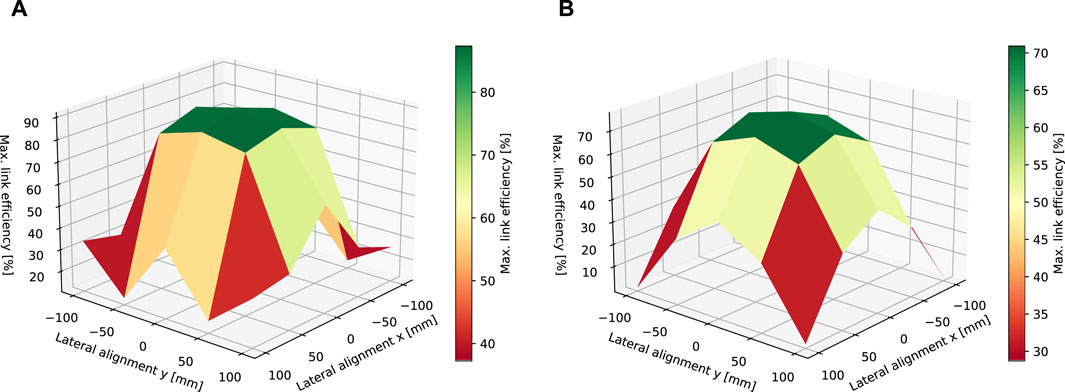
Figure 6. Graphical representation of the maximum attainable link efficiency, as derived from FEM results, under optimal load conditions. (A) Coil-to-coil distance 50 mm. (B) Coil-to-coil distance 100 mm
These results indicate that efficiencies across the WPT link can exceed 70% at coil-to-coil distances up to 100 mm. However, as lateral distances increase, achievable efficiencies rapidly decline.
4 Charging system design and implementation
The design of the UAV-based charging system can pay attention to achieve the maximum attainable link efficiency as discussed in Section 3.1.3. Furthermore, other blocks are also necessary to transfer energy from the UAV battery to the LTO cell. These additional blocks are discussed in Section 4.1, further zooming in on the receiver and transmitter units (in Section 4.2; Section 4.3 respectively), and the data communication (Section 4.4).
4.1 WPT building blocks
The transmitter depicted in Figure 2 includes separate blocks to actually enable wireless power transfer and act as the AC source. The UAV battery is connected to a pre-regulator, essentially a DC-DC converter, allowing the voltage to be dynamically controlled by the processing unit of the WPT transmitter. This variable voltage is then connected to the power inverter. The inverter transforms the pre-regulator DC voltage into a square wave signal with a frequency of 6.78 MHz. Subsequently, a zero voltage switching (ZVS) circuit is placed between the inverter output and the primary LC tank. These blocks are further explained in Section 4.3.
On the receiver side, the IoT node, the alternating magnetic field is captured by the receiver LC tank and then rectified to a DC voltage. This AC-DC conversion comes with associated losses, where the diode threshold voltage determines the efficiency. Typically, Schottky diodes are selected due to their lower forward voltage levels. The last crucial element is the DC-DC converter, which ensures the charging process of the LTO cell. The DC-DC converter is set up as a constant current (CC)/constant voltage (CV) power supply. The RL in Figure 2 thus encompasses the AC-DC conversion, the DC-DC CC/CV charger, and the LTO cell itself. These additional electronic components are required to make an IoT device compatible with these approach and thus convert the alternating magnetic fields to energy and consequently charge the battery.
Figure 5 presents a full render of all components to enable wireless power transfer and ensure the UAV can fly.
4.2 Power receiving unit (PRU)
The IoT device and PRU presented in Figure 5 have been integrated into a single unit and are connected with (1) a receiver coil (2) a LPWAN modem (e.g., long range (LoRa) connection) and (3) one or more sensors or actuators. Therefore, having an onboard Microcontroller Unit (MCU) to communicate with the sensors and LPWAN modem is needed. A nordic NRF52832 system-on-chip (SoC) with Bluetooth Low Energy (BLE) functionality has been selected and is utilized to control both the charging process and IoT-related tasks. During the charging process, a BLE link between the IoT device and the UAV is established to facilitate real-time communication of input voltages, charge voltages and charge currents. The PTU can respond to this measurement data by, for example, fine-tuning the alignment or adjusting the pre-regulator voltage. During normal IoT operation, the SoC can manage IoT-related tasks, such as capturing and processing sensor data and forwarding the results via the LPWAN modem to the cloud.
This section further comprehensively describes the PRU depicted in Figure 5. This charger circuit features several properties required for a safe and reliable charge. It can be divided into four main features: the charging circuitry itself, input voltage protection, leakage current reduction and charge suppression. Figure 7 represents the charging circuit.
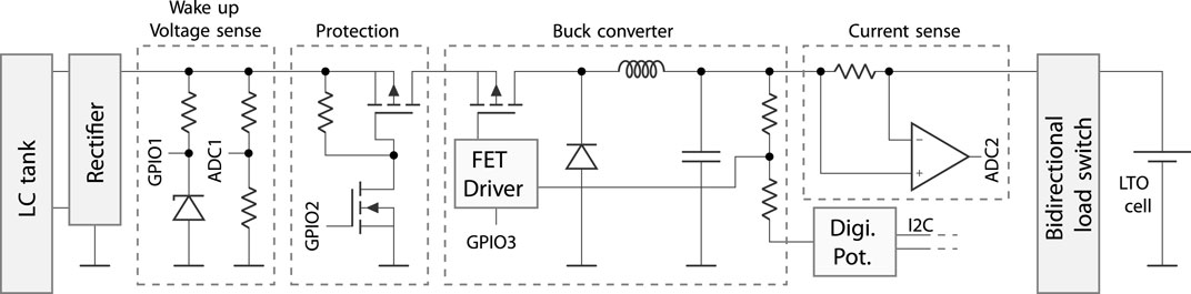
Figure 7. Schematic representation of charging circuit. GPIO1, GPIO2, and GPIO3 correspond to the wake-up input, protection enable output, and buck enable output, respectively. ADC1, and ADC2 enable the measurement of input voltage and output current. (MCU and IoT-related parts not depicted here.)
The core of the charging circuit is a buck converter whose feedback loop voltage divider can be adjusted with a programmable potentiometer. The current can be reduced by adjusting the feedback loop and is measured with a shunt resistor and opamp. This analog voltage is fed to the MCU. The latter can adjust the digital potentiometer via the I2C interface.
The field-effect transistor (FET) and FET driver from the buck converter circuit in Figure 7 are integrated in a buck converter integrated circuit (IC) and can handle input voltages up to 28 V. In wireless power transfer systems, the open circuit voltage of the LC tank can exceed this maximum voltage barrier and could damage the charging circuitry. A load switch design with a sufficient high input range will only pass voltages if a save level is measured. An MCU, powered by the LTO cell, measures the input voltage and drives the load switch to connect the LC tank voltage to the buck converter input to start the charging process.
Many battery-powered devices are charged with a wall adapter. In these devices, the quiescent currents generated by the connected adapter circuit do pose significant autonomy problems. The impact of quiescent currents, caused by the non-active charging circuit, for large battery capacities is much lower compared to small battery capacities. In the considered devices, the LTO cell has a low capacity. Therefore, the quiescent current should also be very low. An additional bidirectional load switch is provided that disconnects the charger from the LTO cell and permits the flow of current from the charger to the cell. This approach is preferred over using a diode due to the additional diode losses, voltage drops, and reverse diode currents. The predicted autonomy, in the absence of any application, or LTO self-discharge is determined by dividing the available capacity (60 mAh) by the leakage current (1.5 µA), resulting in an estimated operational duration of approximately 4.5 years.
If the rectifier voltage is too low, it indicates a suboptimal coil alignment. A buck converter supplied with insufficient input voltage cannot operate effectively, necessitating reduced charging. This charge suppression becomes active at a rectified voltage lower than 10 V and is achieved by adjusting the digital potentiometer. This adjusted resistance in the feedback loop of the buck converter leads to a reduction in output voltage and, consequently, output current.
The efficiency of the building blocks from Figure 7 was assessed by applying a direct current (DC) voltage behind the LC tank. The experiment utilized an Agilent 6632B power supply functioning as a battery emulator, capable of both sourcing and sinking current. Figure 8 presents the efficiency corresponding to the input voltage across multiple output power levels. This measurement clearly indicates that achieving an efficiency higher than 80% remains unattainable. The (DC) rectifier losses constitute a significant contribution to the total losses, along with losses in the converter itself. Furthermore, it is observed that the DC/DC converter achieves its peak efficiency at around 10 V.
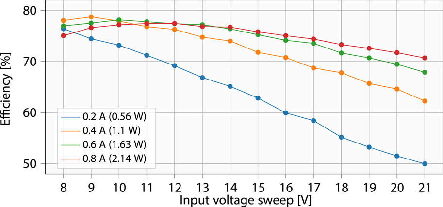
Figure 8. Efficiency measurement of the PRU, including losses in the rectifier, voltage protection circuit, buck converter, shunt resistor, and load switch.
The charging process concludes when the charge current drops below 200 mA and the voltage exceeds 2.6 V for a duration of more than 10 s, indicating the charging process has succeeded. Additionally, if the UAV leaves the node earlier than expected, the IoT node transitions to power-down mode when it observes that the input voltage drops below 1 V.
4.3 Power transmitting unit (PTU)
The central function of the PTU board is to generate a 6.78 MHz sine wave with variable amplitude. Both pre-regulator and inverter board from Figure 5 needs to be as compact and lightweight as possible. The main functions are discussed in this section. The PTU design, illustrating its main components, is depicted in Figure 9.
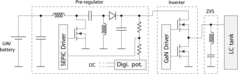
Figure 9. PTU hardware design and components. This board contains additional hardware to measure the voltage and current levels before and after the pre-regulator.
The pre-regulator board from Figure 5 gets its voltage from the UAV battery and forwards this voltage to the flight controller. Moreover, the battery voltage is on-board wired to a single-ended primary-inductor converter (SEPIC) buck-boost converter, which serves as the pre-regulator to modify the input voltage of the half-bridge inverter to strengthen or weaken the alternating magnetic field. The pre-regulator output voltage is adjustable with a programmable potentiometer. This latter is controlled by the MCU via an I2C interface. The pre-regulator input, output current and UAV battery voltage and current on the power supply board can additionally be monitored through this I2C interface.
ZVS or soft switching is ensured by a half-bridge inverter combined with an LC resonant circuit to turn the high and low side FETs at zero voltage on and off, meaning that the efficiency will be higher compared to hard switching approaches (Xue and Zhang, 2017). Since the frequency does not change over time in an MRC system, unlike other IPT implementations, soft switching can be implemented in a low-complex manner, as the ZVS components do not need to undergo changes during operation. To further reduce switching losses, galliumnitride (GaN) FETs were selected. The EPC8010 FETs are driven by a GaN driver.
The presented PTU design is partially based on the evaluation board EPC9512 (Efficienct Power Conversion, 2017), with several modifications to improve the control possibilities and compactness. These modifications include the addition of an MCU, the reduction from a full-bridge inverter to a half-bridge inverter, a more appropriate and down-scaled pre-regulator implementation and a separation of the pre-regulator and the power inverter to efficiently utilize the limited UAV space. As presented in Figure 5, the location of the supply circuit differs from that of the inverter circuit, resulting in two separated PCB designs connected with each other by a flat cable.
Similar to the PRU, an NRF52832 NORDIC SoC is selected to transceive BLE commands with the logger and the PRU. Additionally, it controls the pre-regulator output voltage, reads current levels, and voltage levels. By combining the current and voltages originating from the PRU, the PTU can calculate the efficiency in real time.
4.4 Data communication
The data communication, presented in Figure 2, consists of the Automatic Frequency Hopping Digital System Second Generation (AFHDS2A) communication between the remote controller and UAV, IoT LPWAN communication primarily for sensor data, and the PRU-PTU-logger communication. The latter enables real-time link efficiency improvements during the charging process, and is here briefly explained.
During the charging process, the equivalent load of the battery cell Rcell will vary over time and both the voltage across and the current through the cell are functions of time. The equivalent AC-load RL, after the secondary LC tank, can be adjusted by changing the pre-regulator voltage. With increasing VS, the voltage at the output of the rectifier will increase, causing the current in the DC-DC converter to decrease, thereby altering the load RL on the secondary side. To facilitate these real-time link efficiency improvements, the PRU should provide the PTU with information about the rectifier voltage, charging current, and charging voltage via the communication link. This enables the PTU to adjust the pre-regulator voltage.
This paper primarily focuses on the hardware design and the assessment of achievable efficiency and sustainability aspects. The communication between PRU and PTU can be further expanded in future work. To support interoperability, the Airfuel alliance resonant baseline system specification can be considered (IEC Central Office, 2017). This specification outlines the interface for coupled WPT, including MRC systems.
During the design, validation phase, and also the experimental measurements in Section 5, the communication was limited to sending advertising unidirectional messages from the PTU and PRU to the logger.
5 System validation and experimental performance assessment
The designs and implementations proposed in Section 4 were integrated in the full system and can be consulted in our repository (Van Mulders, 2023 b). The WPT system is validated in this section. During the measurements, all components were placed on the UAV to better approximate real-world conditions.
The Agilent 6632B power supply, mentioned in Section 4.2, is reused to measure the consumed power at the output of the PRU charger and act as an LTO cell. The half-bridge inverter in combination with the transmit coil is crucial for generating the alternating magnetic field. The SEPIC DC/DC converter, situated on this PTU, is not used in the measurements. Alternatively, a voltage source is directly connected to the input of the half-bridge inverter or more specifically to the drain of the high-side GaN FET. This allows us to manually adjust the supply voltage and consequently, adjust the strength of the alternating magnetic field. The measurement setup is depicted in Figure 10.
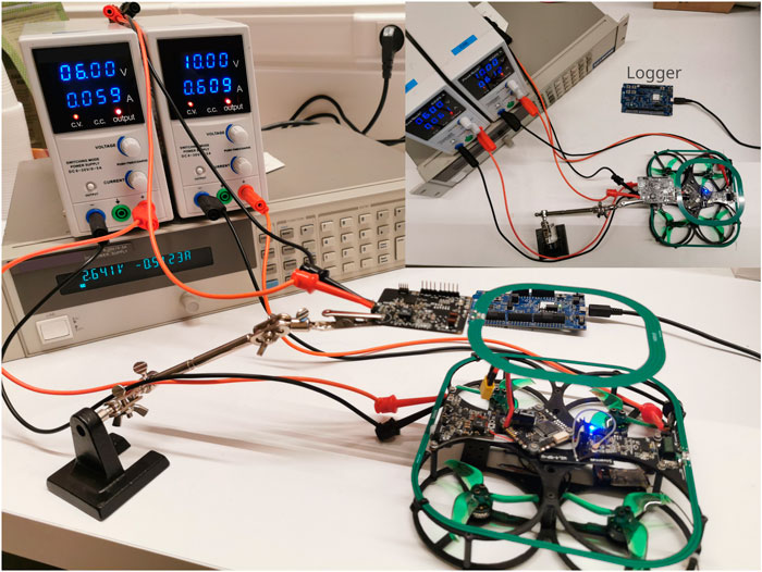
Figure 10. Measurement setup: The left and right voltage sources supply the digital logic and the half-bridge inverter, respectively. The lower power supply acts as the battery emulator.
A static measurement has been conducted with the UAV located on the table. Changing the PRU-to-PTU distance and measuring the input and output power provides us with the measured efficiencies as a function of the vertical distance between the coils. The measurement results are given in Figure 11.
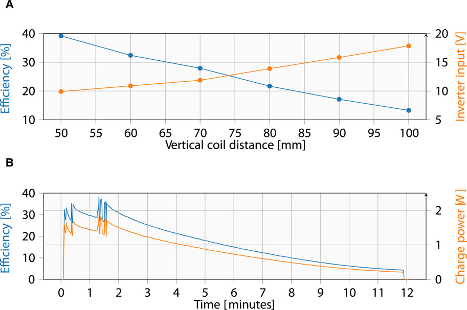
Figure 11. System efficiency measurements with the pre-regulator bypassed. (A) Efficiency related to the coil-to-coil distance for battery voltage of 2.43 V and charge current of 0.55 A. (B) Charge power and system efficiency for charging an LTO cell wirelessly with coil-to-coil distance of 50 mm and a constant inverter input voltage of 10 V.
With an increasing coil-to-coil distance, the voltage after the rectifier will decrease, which can result in an insufficient voltage to power the PRU charger. From Figure 11A, it is evident that VS must be increased significantly to still transfer the same amount of power with increasing vertical distance between the coils. In these measurements, the optimal point of 10 V after the rectifier of the PRU was always approached, since this gives the best PRU efficiency as presented in Figure 8. The inverter voltage must consistently be elevated with caution. The losses in the PTU circuit increase drastically, potentially leading to heating issues. This explains the efficiency drop from 40% to less than 10% at distances of 50 and 100 mm, respectively.
To conclude this analysis, the efficiency was measured during a charge cycle of the LTO cell with a coil-to-coil distance of 50 mm. The delivered battery power and the overall efficiency as functions of the charging time is depicted in Figure 11B. In the first 90 s, the power remains quasi-constant due to the CC charging, and then decreases over time. During this period, the PRU firmware restricts the current to approximately 600 mA. In total the UAV delivered a 60 mAh or 575 J to the LTO cell. For this measurement, the pre-regulator was bypassed, and the inverter supply voltage remained at a constant level of 10 V. After 6 min the LTO cell had a state of charge (SoC) of 75%.
In the final system design and operation, the BLE feedback loop, as depicted in Figure 2, can be engaged to send the charge voltage and current to the UAV. In conjunction with the pre-regulator voltage, the UAV may decide to initiate a realignment procedure when the efficiency falls below a certain threshold. Consequently, the feedback loop should guarantee optimal efficiency and prevent reduced charging.
We recall that the current prototype was designed for the scenario where the UAV hovers during the charging of the IoT node. It is not suited for the scenario where the UAV would land to perform the charging, as the coupling factor would become too high, impacting the self-inductance of the coils and thus the resonance frequency of the LC tanks.
6 Sustainability analysis of the proposed solution
When examining sustainability, which is a term with a broad meaning, in electronics design conventional methods tend to concentrate solely on the system’s energy consumption. While this may be an important factor in some cases, it may not be in others. In low-power IoT systems, it has been shown that the environmental impact of the hardware extends far beyond its energy consumption alone (Ercan et al., 2016). In this section, we look beyond the singular metric of energy consumption and comprehensively address the sustainability aspects of the proposed UAV-based charging solution, embracing a more holistic perspective.
Section 6.1 addresses the production phase of the devices, while Section 6.2 focuses on the actual deployment and the environmental burden or benefits of the servicing approach.
6.1 Analysis of overhead in UAV approach
We conducted a life cycle assessment (LCA) to encompass the majority of the solution-related environmental impacts throughout its lifespan. We mainly focus on the electronics at the IoT node side. The impact of the UAV has been modeled, excluding the WPT circuit. The impact, attributable to the WPT circuit, can be distributed over the entire lifespan of the UAV, given its substantial flight hours. As a result, the WPT overhead on the UAV side is expected to have a negligible contribution to the overall environmental impact. The modeling is conducted for a cradle-to-gate analysis (production phase) using the Sphera professional and Sphera Extension database XI (Electronics) (Sphera, 2023) using the ReCiPe 2016 midpoint (H) method. As the end of life (EoL) processing of electronics has typically a rather small environmental impact compared to the total picture (Pirson and Bol, 2021), and the modeling of these EoL scenarios is lacking in LCA databases, we here do not consider the EoL component. It is important to note that we specifically consider the Global Warming Potential (GWP) as a metric for sustainability. This only brings a partial analysis and can lead to the so-called ‘carbon tunnel vision’. There are plenty of other impact categories and metrics that need attention, but are out of scope for this paper.
Figure 12 depicts the total overhead needed at the IoT node side for the UAV-based servicing approach. We here made some assumptions to model the overhead as correctly as possible. The BLE IC was only taken into account for 50% of its GWP, since this IC can also be used as an application microcontroller. For the PCB modeling, a 2-layer PCB with 2/3 of the original size was used, since the microcontroller area is also partially needed in the application, but the BLE PCB antenna needs to be included specifically for the charging process. The passive components are modeled according to their closest database match. Since LCA models for special types of Lithium-Ion batteries are not broadly available at the time of writing, the LTO battery is modeled according to a standard Li-Ion battery, recalculated proportional to the weight energy density difference.
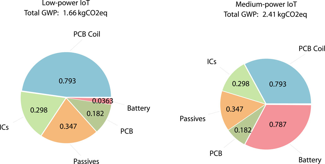
Figure 12. Contribution of different parts of the IoT node, modified for UAV-based charging, to the GWP (in kgCO2eq).
Two IoT systems were considered, one low-power (10 J/d) and one with medium power consumption (200 J/d). The batteries were chosen accordingly, such that the device could operate for ±2 months on a single battery charge. The biggest contribution to the total GWP is observed to be in the PCB, battery, and passive components, depending on the device’s power requirements. The low-power system has a GWP of 1.66 kgCO2eq, from which the PCB coil is the biggest contributor. One can observe that the small battery has a very limited impact. In comparison to a standard IoT device, where the battery plays a substantial role in the device’s overall GWP, using a compact battery leads to a considerably reduced environmental impact during production. Whether this benefit offsets the additional GWP from energy harvesting during UAV deployment is dependent on specific situations. In the medium-powered system, however, we observe a larger battery capacity is needed to ensure the same lifetime. This translates into an added environmental burden in the manufacturing process.
6.2 Comparison between UAV and traditional remote IoT deployments
Examining only the fabrication fails to provide a comprehensive overview. We here look at the total carbon footprint, generated throughout the lifetime of the IoT node, including potential device or battery recharges/replacements. We compare a typical approach, where an IoT device would be powered by non-rechargeable batteries, to the novel UAV-based energy provisioning solution proposed in this work. Two situations are considered.
1. The proposed solution for which the design is detailed in this paper, where the UAV can recharge an ultra-low-power IoT device, consuming 10 J/d. This is equivalent to, e.g., a temperature measurement and a LoRa transmission every 30 min. We here used an LTO battery with a capacity of 0.144 W h (60 mAh at 2.4 V) (HuaHui, 2023).
2. An extended use-case, with a medium-powered IoT application, consuming 200 J/d. To be able to power the IoT device for a sustained period, we here assume a bigger LTO battery of 3.12 W h (1.3 Ah at 2.4 V) (HuaHui, 2023). In this case, the current setup cannot charge the battery fast enough while hovering, so a landing alternative is proposed to be able to transfer the full amount of energy.
In the UAV approach, we consider the base IoT manufacturing impact together with the additional WPT hardware, and the UAV itself. In the reference case, the same IoT manufacturing impact is used while also accounting for the impact of the battery. The UAV is modeled based on the work in (Pirson and Bol, 2021), assuming optimal usage, i.e., for 400 flight hours before needing replacement, hereby also taking into account battery degradation and thus replacements. Depending on the goal and size of the IoT device, the environmental impact ranges from 1 kgCO2eq to 10 kgCO2eq (Pirson and Bol, 2021). We here assume a relatively simple and small IoT device with a GWP of 3 kgCO2eq. For the non-rechargeable (traditional) IoT, we considered manual replacement with no environmental impact. This could range from a few grams to almost 1 kgCO2eq, when, e.g., driving a car several kilometers.
The results are depicted in Figure 13. In the case of the low-power IoT node, the UAV-based servicing/recharging approach is not beneficial compared to a traditional approach (using non-rechargeable batteries) in terms of absolute GWP. However, in hard-to-reach applications in, e.g., rural locations, where battery replacement is infrequent, a new device is typically introduced to replace the old one every 5 years. This periodic replacement has a higher ecological impact than the UAV-based approach starting from the fourth operational year. In a worst-case scenario, where replacements occur annually, the advantages of the UAV-based approach become more evident and surpass the traditional approach already after 6 months. In the medium-power IoT, we observe that the battery becomes significantly large, providing only a 6 months lifespan with a battery of 10 Wh. This is a scenario where the UAV-based approach could bring significant benefit in reducing the total environmental impact. However, it is worth noting that such applications may also opt for rechargeable batteries, as employing very large non-rechargeable batteries becomes impractical.
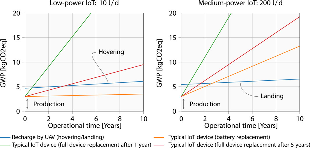
Figure 13. Comparison in average environmental impact of low- and medium-powered UAV devices with different servicing methods.
6.3 Concluding remarks and future opportunities regarding sustainable design
While the proposed approach may show a higher environmental impact in terms of GWP compared to conventional ultra-low-power IoT systems, its sustainability advantage lies in overcoming the inherent limitations of conventional systems, where the battery size restricts the device’s lifespan. The proposed approach may prove more sustainable for applications with higher energy requirements, utilizing larger batteries at the IoT node with enhanced energy transfer capabilities. The system, with its theoretical capability for an infinite extension of the device’s lifespan, presents a substantial benefit by potentially reducing the need for device replacements. The sustainability of the UAV-based system hinges on the durability of its components, suggesting potential longevity over several decades. Despite an initial burden in the UAV case due to the necessity for additional WPT hardware, this drawback may be outweighed by the extended lifespan of devices. Lifetimes up to 20 years and longer have been envisioned for IoT applications, for which foreseeing all the energy in batteries from day 1 increasingly becomes very costly, not practical at all due to the consequentially huge battery and comes with a high ecological impact. Besides environmental considerations, the convenience of fully automated energy provisioning solutions introduces numerous possibilities for future applications.
7 Conclusion and future work
This work addressed the challenges of ensuring sustained power autonomy for battery-powered remote IoT devices through a novel and efficient recharging paradigm: UAV-based charging using a magnetic resonance coupling approach. An analytical study clarified the trade-offs to be made to reach a good efficiency, quantified the expected impact of misalignment between the coils during the charging, and allowed to optimize the parameters of the wireless power transfer components. An actual design compatible with the constraints imposed by the UAV on which it has to be mounted, was elaborated, implemented, and measured. The WPT was validated, demonstrating its feasibility with good transfer efficiency and highlighting its positive implications for longevity and sustainability. The paper further presented an analysis of the sustainability aspects of the UAV-based solution, considering not only energy consumption but also taking into account the environmental impact of the hardware itself. From this we can conclude that the novel approach can not only bring about the longevity of remote IoT nodes, it can moreover accomplish this at a relatively low ecological footprint, in particular for devices with medium to larger power needs.
In the future, we envision deploying such systems, for example, to support sound monitoring in scenarios where typical computation-intensive tasks are much more demanding, resulting in significantly lower autonomy if a non rechargeable battery cell would have gained preference. We of course intend to extend the proof of concept to an actual flying and hovering UAV. Further extension can consider higher power densities, and additional options to improve efficiency as suggested in the course of this paper. This involves enhancing the algorithm to adjust the voltage of the pre-regulator so that optimal load conditions are consistently met. We can further investigate whether angular differences between the coils in windy conditions do not significantly impact the charging process. Additionally, the UAV will need to be equipped with a fine-grained localization system to achieve alignment with the receiver coil. Additionally, an actual measurement campaign can provide clarification on the feasibility and deployability of this UAV-based charging solution.
Data availability statement
The raw data supporting the conclusion of this article will be made available by the authors, without undue reservation.
Author contributions
JV: Conceptualization, Formal Analysis, Investigation, Methodology, Software, Validation, Visualization, Writing–original draft. SB: Formal Analysis, Investigation, Methodology, Writing–original draft. JC: Conceptualization, Formal Analysis, Investigation, Methodology, Visualization, Writing–original draft. LV: Supervision, Writing–review and editing. LD: Supervision, Writing–review and editing.
Funding
The author(s) declare financial support was received for the research, authorship, and/or publication of this article. This research was partially funded by Flanders Innovation and Entrepreneurship (VLAIO), grant number HBC.2021.0797 and Cochlear Technology Centre. The results are partly funded by the Flanders Innovation & Entrepreneurship (VLAIO) project E-CONSTRUCT under grant number HBC.2021.0911.
Acknowledgments
We would like to express our gratitude to the advisors Peter Cox (Engineer at BelGaN Belgium) and Jan Cappelle (Professor at KU Leuven) for their valuable input, which contributed to the improvement of this work.
Conflict of interest
The authors declare that the research was conducted in the absence of any commercial or financial relationships that could be construed as a potential conflict of interest.
Publisher’s note
All claims expressed in this article are solely those of the authors and do not necessarily represent those of their affiliated organizations, or those of the publisher, the editors and the reviewers. Any product that may be evaluated in this article, or claim that may be made by its manufacturer, is not guaranteed or endorsed by the publisher.
References
Ahn, D., and Hong, S. (2013). A study on magnetic field repeater in wireless power transfer. IEEE Trans. Ind. Electron. 60 (1), 360–371. doi:10.1109/tie.2012.2188254
ANSYS, Inc (2023). ANSYS Maxwell. Available at: https://www.ansys.com/products/electronics/ansys-maxwell (Accessed November 17, 2023).
Asadzadeh, S., de Oliveira, W. J., and de Souza Filho, C. R. (2022). UAV-based remote sensing for the petroleum industry and environmental monitoring: state-of-the-art and perspectives. J. Petroleum Sci. Eng. 208, 109633. doi:10.1016/j.petrol.2021.109633
Baker, M. W., and Sarpeshkar, R. (2007). Feedback analysis and design of RF power links for low-power bionic systems. IEEE Trans. Biomed. Circuits Syst. 1 (1), 28–38. doi:10.1109/tbcas.2007.893180
Callebaut, G., Leenders, G., Van Mulders, J., Ottoy, G., De Strycker, L., and Van der Perre, L. (2024). The art of designing remote iot devices–technologies and strategies for a long battery life. Sensors 21 (3), 913. doi:10.3390/s21030913
Cetinkaya, O., Balsamo, D., and Merrett, G. V. (2020). Internet of MIMO Things: UAV-assisted wireless-powered networks for future smart cities. IEEE Internet Things Mag. 3 (1), 8–13. doi:10.1109/IOTM.0001.1900064
Cui, Z., Guan, K., Oestges, C., Briso-Rodríguez, C., Ai, B., and Zhong, Z. (2022). Cluster-based characterization and modeling for UAV air-to-ground time-varying channels. IEEE Trans. Veh. Technol. 71 (7), 6872–6883. doi:10.1109/TVT.2022.3168073
EASA (2015). Open category - civil drones. Available at: https://www.easa.europa.eu/en/domains/civil-drones/drones-regulatory-framework-background (Accessed November 17, 2023).
Ercan, M., Malmodin, J., Bergmark, P., Kimfalk, E., and Nilsson, E. (2016). “Life cycle assessment of a smartphone,” in Proceedings of ICT for sustainability 2016 (Amsterdam, Netherlands: Atlantis Press), 124–133. doi:10.2991/ict4s-16.2016.15
Hackl, S., Lanschutzer, C., Raggam, P., and Randeu, W. (2008). “A novel method for determining the mutual inductance for 13.56 MHz RFID systems,” in 2008 6th international symposium on communication systems, networks and digital signal processing (IEEE), 297–300. doi:10.1109/CSNDSP.2008.4610726
Hemmati, A., Zarei, M., and Souri, A. (2023). UAV-based Internet of Vehicles: a systematic literature review. Intelligent Syst. Appl. 18, 200226. doi:10.1016/j.iswa.2023.200226
Hentati, A. I., and Fourati, L. C. (2020). Comprehensive survey of UAVs communication networks. Comput. Stand. Interfaces 72, 103451. doi:10.1016/j.csi.2020.103451
HuaHui (2023). HTC lithium titanate battery. Available at: https://sc02.alicdn.com/kf/H6facf0082efb4bd2a9027-ae9b080d858C/230614295/H6facf0082efb4bd2a9027ae9b080d858C.jpg (Accessed November 17, 2023).
IEC Central Office (2017). “Wireless power transfer Airfuel alliance resonant baseline system specification (BSS),” in Standard IEC 63028:2017 (Geneva, CH: International Organization for Standardization).
Jeon, S.-J., and Seo, D.-W. (2019). Coupling coefficient measurement method with simple procedures using a two-port network analyzer for a multi-coil WPT system. Energies 12 (20), 3950. doi:10.3390/en12203950
Jiang, H., Zhang, Z., and Gui, G. (2019). Three-dimensional non-stationary wideband geometry-based UAV channel model for A2G communication environments. IEEE Access 7, 26116–26122. doi:10.1109/ACCESS.2019.2897431
Khelifi, F., Bradai, A., Singh, K., and Atri, M. (2018). Localization and energy-efficient data routing for unmanned aerial vehicles: fuzzy-logic-based approach. IEEE Commun. Mag. 56 (4), 129–133. doi:10.1109/MCOM.2018.1700453
Ojha, T., Raptis, T. P., Passarella, A., and Conti, M. (2023). “Wireless power transfer with unmanned aerial vehicles: state of the art and open challenges,” in Pervasive and mobile computing, 101820. doi:10.1016/j.pmcj.2023.101820
Pirson, T., and Bol, D. (2021). Assessing the embodied carbon footprint of IoT edge devices with a bottom-up life-cycle approach. J. Clean. Prod. 322, 128966. doi:10.1016/j.jclepro.2021.128966
Rindorf, L., Lading, L., and Breinbjerg, O. (2008). “Resonantly coupled antennas for passive sensors,” in 2008 IEEE sensors (IEEE), 1611–1614. doi:10.1109/icsens.2008.4716759
Rohan, A., Rabah, M., Asghar, F., Talha, M., and Kim, S.-H. (2019). Advanced drone battery charging system. J. Electr. Eng. Technol. 14, 1395–1405. doi:10.1007/s42835-019-00119-8
Rosa, E. B. (1908). The self and mutual inductances of linear conductors, number 80, US Department of Commerce and Labor. Bureau of Standards.
Salam, A. (2020). Internet of Things for sustainable community development: wireless communications, sensing, and systems. Springer International Publishing. doi:10.1007/978-3-030-35291-2_5
Shaikh, F. K., and Zeadally, S. (2016). Energy harvesting in wireless sensor networks: a comprehensive review. Renew. Sustain. Energy Rev. 55, 1041–1054. doi:10.1016/j.rser.2015.11.010
Shaikh, F. K., Zeadally, S., Tapparello, C., Ayatollahi, H., and Heinzelman, W. (2018). Energy-harvesting wireless sensor networks (EH-WSNs): a review. ACM Trans. Sen. Netw. 14 (2), 1–50. doi:10.1145/3183338
Shuo Liu, J. S., and Lai, J. (2019). Accurate expressions of mutual inductance and their calculation of archimedean spiral coils. Energies 12 (10), 2017. doi:10.3390/en12102017
Sphera (2023). Product sustainability (GaBi) data search Sphera. Available at: https://sphera.com/product-sustainability-gabi-data-search/ (Accessed November 17, 2023).
Van Mulders, J. (2023). Coil coupling factor reading with VNA. Available at: https://github.com/jarnevanmulders/Coil-Coupling-Factor-Reading-with-VNA (Accessed December 20, 2023).
Van Mulders, J. (2023). UAV based charging solution. Available at: https://github.com/jarnevanmulders/UAV-Based-Charging-Solution (Accessed December 20, 2023).
Van Mulders, J., Cappelle, J., Goossens, S., De Strycker, L., and Van der Perre, L. (2023). UAV-based servicing of IoT nodes: assessment of ecological impact. Sensors 23 (4), 2291. doi:10.3390/s23042291
Van Mulders, J., Delabie, D., Lecluyse, C., Buyle, C., Callebaut, G., Van der Perre, L., et al. (2022). Wireless power transfer: systems, circuits, standards, and use cases. Sensors 22 (15), 5573. doi:10.3390/s22155573
Van Mulders, J., Leenders, G., Callebaut, G., De Strycker, L., and Van der Perre, L. (2022). “Aerial energy provisioning for massive energy-constrained IoT by UAVs,” in ICC 2022-IEEE international conference on communications (IEEE), 3574–3579. doi:10.1109/ICC45855.2022.9838284
Vom Bögel, G., Cousin, L., Iversen, N., Ebeid, E. S. M., and Hennig, A. (2020). “Drones for inspection of overhead power lines with recharge function,” in 2020 23rd euromicro conference on digital system design (DSD), 497–502. doi:10.1109/DSD51259.2020.00084
Xue, L., and Zhang, J. (2017). “Single-stage 6.78 MHz power-amplifier design using high-voltage GaN power ICs for wireless charging applications,” in 2017 IEEE applied power electronics conference and exposition (APEC) (IEEE), 3743–3750. doi:10.1109/APEC.2017.7931237
Keywords: internet of things, wireless power transmission, energy efficiency, carbon footprint, life cycle assessment
Citation: Van Mulders J, Boeckx S, Cappelle J, Van der Perre L and De Strycker L (2024) UAV-based solution for extending the lifetime of IoT devices: efficiency, design and sustainability. Front. Comms. Net 5:1341081. doi: 10.3389/frcmn.2024.1341081
Received: 19 November 2023; Accepted: 20 March 2024;
Published: 10 April 2024.
Edited by:
Ke Guan, Beijing Jiaotong University, ChinaReviewed by:
Hao Jiang, Nanjing University of Information Science and Technology, ChinaMeiwen Zhang, Beijing Jiaotong University, China
Michael Kuhn, Darmstadt University of Applied Sciences, Germany
Copyright © 2024 Van Mulders, Boeckx, Cappelle, Van der Perre and De Strycker. This is an open-access article distributed under the terms of the Creative Commons Attribution License (CC BY). The use, distribution or reproduction in other forums is permitted, provided the original author(s) and the copyright owner(s) are credited and that the original publication in this journal is cited, in accordance with accepted academic practice. No use, distribution or reproduction is permitted which does not comply with these terms.
*Correspondence: Jarne Van Mulders, amFybmUudmFubXVsZGVyc0BrdWxldXZlbi5iZQ==