 Mahmoud Raeisi
 Asil Koc
 Ertugrul Basar
 Tho Le-Ngoc
- 1Department of Electric and Electronic Engineering, Koc University, Istanbul, Turkey
- 2Department of Electrical and Computer Engineering, McGill University, Montreal, QC, Canada
In this study, a novel cluster index modulation (CIM) scheme, which is based on indexing the available clusters in the environment, is proposed for future mmWave communication systems. Exploiting the fact that the available clusters in the system are well separated in terms of their angular distribution, we selected the best path for each of them and then performed IM in an algorithmic manner to convey information bits. It is shown that by means of large antenna arrays and analog RF beamforming with the indexed clusters, the destructive effect of inter-beam/cluster interference can be remarkably mitigated. Also, we designed a hybrid beamforming architecture at the transmitter to further reduce the effect of residual inter-beam/cluster interference, where the analog RF beamformer is followed by a digital baseband precoder using the zero-forcing technique. Computer simulations reveal that the proposed scheme can provide better error performance than traditional mmWave communication, and the proposed hybrid architecture outperforms beam index modulation (BIM) for a point-to-point scenario. Semi-analytical derivations and closed-form unconditional pairwise error probability (UPEP) expressions are derived for both analog and hybrid architectures, which confirm the validity and superiority of our proposed scheme.
1 Introduction
With increasing demands for a higher data rate and spectrum usage, new technologies and novel techniques for future wireless systems are needed. One of the most promising technologies with a large available spectrum is millimeter wave (mmWave) communication (Zhou et al. (2018); Sun et al. (2014); Rappaport et al. (2015); Niu et al. (2015)). Nonetheless, mmWave signals suffer significant path loss due to a sparse-scattered environment (Perović et al. (2016); Heath et al. (2016)). To compensate the effect of path loss, mmWave systems should employ large antenna arrays in both the transmitter and receiver to leverage beamforming gain. Deployment of large antenna arrays in a compact size is possible, thanks to short wavelength of mmWave communications (El Ayach et al. (2014); Xiao et al. (2017)). Normally, in sub-6 GHz systems, MIMO arrays are fully digital, where each antenna element connects to a single RF chain. However, for mmWave systems with large antenna arrays, it is costly and power-consuming to have a huge number of RF chains (Raafat et al. (2018)), which necessitates the use of novel techniques to decrease implementation costs. Hybrid beamforming is a key technology to deal with this problem and to reduce the mmWave implementation costs (Li et al. (2020)). It is shown that hybrid beamforming achieves a spectral efficiency close to the fully digital beamforming, and it also greatly enhances energy efficiency for mmWave communication systems with large antenna arrays by significantly reducing the number of RF chains (Koc et al. (2020)). While hybrid beamforming is known as an energy- and cost-efficient method to decrease the number of RF chains, there is still a need for a tremendous number of high-precision phase shifters. To decrease the number of phase shifters implemented in the analog network (Yu et al., 2018), proposed a novel hardware efficient structure by adopting a network of fixed phase shifters. A network of dynamic switches was implemented in order to adapt the analog network to the channel states.
Index modulation (IM) is another promising technology with high spectral and energy efficiencies, in which the transmitter performs indexing building blocks, for example, antenna arrays, paths, and subcarriers, to convey additional bits (Basar, 2016a; Basar et al., 2017). In Yüzgeçcioğlu and Jorswieck (2017), the authors investigated array IM in a mmWave communication system. In this study, the considered system consists of several arrays, and an index in each array is specified. Therefore, according to the spatial symbols, one array is selected and traditional symbols are transmitted through that array. Here, each receiver has to resolve traditional constellation and an array index. In Ding et al. (2017), the authors proposed a scheme named spatial scattering modulation (SSM) by indexing spatial directions of scattering clusters. It has been shown that the SSM scheme can perform better than maximum beamforming and random beamforming in the ideal condition of orthogonal paths, in terms of the bit error rate (BER). However, this study did not consider realistic conditions such that the paths are randomly distributed in the environment and the orthogonality is not guaranteed. Mokh et al. (2019) proposed a hybrid beam index modulation (BIM) scheme by adopting a layer of digital precoding to solve the problem of inter-beam interference in mmWave communication systems. The authors showed that the proposed scheme can boost the system performance in comparison with pure analog BIM, due to cancellation of inter-beam interference. Fan et al. (2020) proposed an anti-Doppler IM for wideband mmWave systems. They proposed a Doppler pre-compensator to assist IM in order to decrease the complexity of a maximum likelihood (ML) detector. With such a scheme, they indicated that error performance enhances. A spatial modulation scheme for the uplink mmWave system was proposed in Wang and Zhang (2019). In this scheme, the authors considered a power iteration algorithm to obtain spatial symbols. With such a spatial codebook, it is possible to find the optimal transmission mode by obtaining a trade-off between spatial domain and signal domain. On the other hand, at the base station (BS), they adopted a round-robin path selection algorithm to ensure that selected paths are separated enough with respect to angle of arrival (AoA). Generalized beamspace modulation (GBM) is proposed in Gao et al. (2019) to enhance multiplexing gain and spectral efficiency. A theoretical analysis and numerical simulations demonstrated that this scheme can perform better than non-GBM schemes in terms of BER and spectral efficiency. Finally, (Perović et al., 2016) studied receive spatial modulation (RSM) for indoor line-of-sight (LOS) mmWave systems. To minimize symbol error probability (SEP), they derived optimal channel conditions, and based on this optimization, they proposed a simple structure for the transmitter and the receiver.
In this study, a mmWave communication scenario in which the paths are uniformly distributed in the environment is studied, and normally, these paths are not orthogonal. In our proposed scheme, named cluster index modulation (CIM), the best path from each cluster is chosen for IM. Due to the well separation of clusters in terms of their angular distribution, the selected paths are also separated. It is worth mentioning that when two paths are physically separated enough, they become near orthogonal. Extensive computer simulations evaluate superiority of the proposed CIM scheme against traditional mmWave communication. Our contributions are summarized as follows:
• A novel IM scheme based on indexing separated clusters in the mmWave communication environment is proposed. Simulation results reveal that our proposed scheme can perform better than traditional mmWave communication in terms of BER in the presence of non-orthogonal paths.
• We proposed hybrid architecture in the transmitter, which benefits from a digital ZF precoder to further mitigate inter-beam interference. Simulation results demonstrated the superiority of our proposed hybrid scheme in comparison with the BIM scheme.
• We studied our scheme in the case of analog and hybrid architectures at the transmitter and derived our semi-analytical derivations and closed-form analytical unconditional pairwise error probability (UPEP) expressions for both architectures, which prove the validity of our proposed scheme. We further noted that our derivations based or semi-analytical models provide useful approximation on the actual BER.
The rest of this article is organized as follows. In Section 2, our channel model has been introduced. The BER performance analysis is given in Section 3. Simulation results are provided in Section 4; and the conclusion of this study can be found in Section 5.
2 System Model
In this section, we presented the proposed system and its generic architecture. Figure 1 illustrates the proposed system model with C clusters in the environment. It is assumed that each cluster consists of several paths with uniformly distributed angle of arrival (AoA) or departure (AoD) within a predefined interval. We considered that the clusters have non-overlapping angular support (i.e., AoA and AoD). Hence, they are well separated from each other. As shown in Figure 1, the number of transmit and receive antennas are assumed as Nt and Nr, respectively. At both the transmitter and the receiver, each antenna element is connected to a phase shifter for the purpose of analog beamforming to compensate the effect of path loss. A point-to-point communication scenario is considered; hence, at the transmitter, we have a single RF chain. At the receiver side, C beams should form simultaneously, where C is the number of indexed clusters; hence, C RF chains are needed at the receiver. With taking into consideration M as the constellation order, the spectral efficiency is given as η = log 2C + log 2M bits per channel use (bpcu).
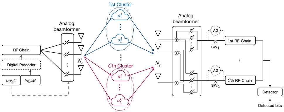
FIGURE 1. CIM system model with analog and hybrid beamforming architecture.
We adopted the Saleh–Valenzuela channel model to characterize a mmWave non-line-of-sight (NLOS) channel in an indoor environment (Ying et al. (2020); Akdeniz et al. (2014)). The channel matrix
where
where
2.1 Analog Beamforming Architecture
In this setup, completely analog architectures are considered at the transmitter and receiver; hence, there is no digital signal processing in the system. The received signal vector
where
where
Analog combiner of l-th path of the i-th cluster can be expressed as follows:
where
In this study, we studied both brute-force and two-stage greedy-maximum likelihood (ML) detectors to analyze the performance of the proposed CIM. To use brute-force detector, all switches (i.e. SWi, i = 1, 2, …, C) should be closed. Afterward, the receiver jointly detects indexed and M-ary bits as follows:
For the case of a greedy-ML detector, amplitude detectors (AD) measure the received power of signals from each cluster to detect the one with the most power; henceforth, the corresponding switch to that path is closed while the other switches remain open. Therefore, we have the first stage detection to resolve indexed bits as follows:
At the second stage, we adopt ML detector to detect M-ary symbols as follows:
2.2 Hybrid Beamforming Architecture
In the hybrid architecture, a digital precoder is adopted at the transmitter to further suppress inter-beam interference and boost the system performance. By applying the zero-forcing (ZF) criterion to the indexed clusters, the transmitter can null the inter-beam interference. The received signal vector y can be expressed as follows:
Notice
where
where ɛ is the normalization scalar and can be obtained as follows:
where tr(.) is the trace operation. It is worth mentioning that, channel characteristics at the transmitter can be obtained via both online and offline approaches (Zheng et al., 2018; Wang et al., 2015; Zhu et al., 2021). The received signal vector after analog combiner can be stated as follows:
where
Finally, in order to jointly detect indexed and M-ary bits, the brute-force detector is defined as follows:
3 BER Performance Analysis
In this section, the BER performance of the proposed analog and hybrid beamforming schemes are derived. We used i* and s* to present the true cluster index and symbol, whereas
3.1 Analog Beamforming Architecture
Using the brute-force detector, conditional pairwise error probability (CPEP) can be stated as follows:
where
To solve CPEP expression, we considered two cases, correct cluster index detection (
3.1.1 Correct Cluster Index Detection
When the cluster index is detected correctly, by using Eq. 6 and right-hand side of Eq. 18, we can derive the following equation:
Therefore, by substituting Eq. 19 and Eq. 20 into Eq. 18, CPEP expression can be as follows:
where
Hence, ζ follows Gaussian distribution with mean μζ and variance
Accordingly, we calculated CPEP for this case as follows:
where Q(.) is the Q-function and defined as follows:
Let us define MA as follows:
Unfortunately, due to complicated distribution of
As an alternative to above approach, we can obtain approximate analytical results by using Distribution Fitter tool in MATLAB. For this purpose, one can obtain probability density function (PDF) of the random part in Eq. 25. Let us define:
Subsequently, Eq. 25 can be rewritten as follows:
wherein g(X) is a function of random variable X. In order to calculate UPEP, we need to take an expectation over g(X), given that X has a PDF of fX(x). Hence, by applying the expectation operation, we can write:
In Section 4, the PDF of X (i.e., fX(x)) is obtained by using the Distribution Fitter tool; then by adopting Eq. 30 and Eq. 31, we acquired approximate analytical results for UPEP.
3.1.2 Erroneous Cluster Index Detection
Considering erroneous detection of the cluster index, by using Eqs 6, 18, the following expression can be derived:
Accordingly, substituting Eq. 19 and Eq. 32 into Eq. 18 results into following CPEP expression:
Let us define
Furthermore, we define
Similarly, χ2 is a central chi-square random variable with two degrees of freedom, which has an exponential distribution with the parameter of
where
To acquire semi-analytical results, we can use the following expression:
where ΛA(t) is the t-th random sample of ΛA and S stands for number of random realizations.
To obtain UPEP by using the Distribution Fitter tool, the random part of Eq. 38 can be considered as follows:
Hence, we can rewrite Eq. 38 as follows:
By taking expectation over h(Y), given that Y has a PDF of fY(y), we can derive UPEP as follows:
In Section 4, we obtain the PDF of Y for the deployed scenario; subsequently, UPEP can be calculated by using Eqs 41, 42.
3.2 Hybrid Beamforming Architecture
By following the same procedure, we can easily calculate CPEP for the hybrid beamforming architecture. Therefore, for the case of
where
Regarding Eq. 43, let us define MH as follows:
Semi-analytical results can be obtained by using the following expression:
where MH(t) is the t-th random sample of MH. Similarly, we can calculate semi-analytical UPEP for the case of
where ΛH(t) is the t-th random sample of ΛH.
To obtain approximate UPEP, the same approach as the analog architecture can be adopted; hereby, we defined
Subsequently, we can rewrite CPEP expressions of Eqs 43, 44 as follows, respectively:
Finally, by taking the expectation over
It is worth noting that in Section 4, we obtained a PDF for
3.3 BER Derivation
We can derive BER using union bound as follows:
where Nb is the total number of transmitted bits, N(i*, s*) is the total number of realizations of i* and s*, and
4 Simulation Results
Two architectures are considered for the proposed scheme, that is, analog and hybrid scheme. First, we provide computer simulation results for the analog scheme. Then the hybrid scheme, which includes a ZF precoder block to suppress inter-beam interference, is analyzed.
4.1 Analog Beamforming Architecture
The number of antenna elements at the transmitter and receiver is considered to be 128. The total number of paths in all clusters is considered to be 20, that is,

TABLE 1. AoA/AoR interval ranges for cluster index modulation (CIM).
In this section, we provide BER comparison of the proposed CIM scheme with traditional mmWave communication, while our system uses a two-stage greedy-ML detector. Our motivation for designing this detector is the insufficient performance of the brute-force detector in terms of BER. Figure 2 illustrates the performance of the greedy-ML detector in comparison with the brute-force detector. In a mmWave system, analog combiners at the receiver can result into different effective noises for each indexed cluster. This results into more errors in the brute-force detector in comparison with the greedy-ML detector. Let us assume a system with two indexed clusters, and cluster one is the correct cluster. Under these circumstances, if the effective noise of the first cluster is more powerful, the greedy-ML detector benefits from it, while the brute-force detector may not detect the symbol correctly. Figure 3 depicts the superiority of the proposed scheme in comparison with traditional communication, wherein the system uses a two-stage greedy-ML detector. The corresponding computer simulation configurations are provided in Table 2. It is noticeable that in the traditional mmWave communication, one can transmit through the best path regarding path gain strength, without considering any IM. As shown in Figure 3, computer simulations for 4 bpcu and 6 bpcu spectral efficiency have been provided. In each case, we compare traditional mmWave communication with one extra bit and two extra bits provided by the proposed scheme, that is, CIM. As we can see, when we adopted our scheme to transmit one extra bit, the performance is better in comparison with traditional mmWave communication. We can improve the BER performance further by transmitting two extra bits. However, when we increased the spectral efficiency, BER increases as well. This is because with increasing spectral efficiency, the distance between M-ary constellation symbols, and the distance among indexed paths decreases; therefore, the receiver has more difficulty to resolve both conventional and spatial symbols.
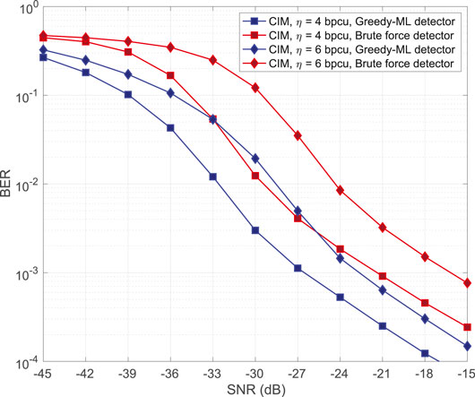
FIGURE 2. BER performance for greedy-ML detector (1 bit CIM).
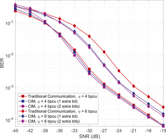
FIGURE 3. BER performance for analog architecture with greedy-ML detector.
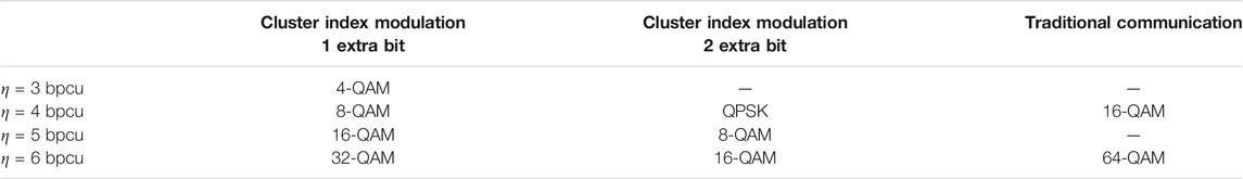
TABLE 2. Simulation parameters.
Figure 4 illustrates BER performance of the proposed scheme and derived a theoretical bound on the BER. As shown in Figure 4, our semi-analytical results behave as an upper bound on the computer simulation results and confirm their validity. Table 2 shows detailed information on the used M-ary constellations. In all cases one extra bit is modulated with CIM.
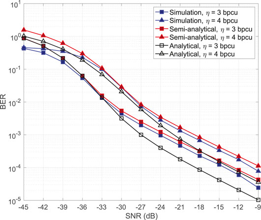
FIGURE 4. Theoretical and simulation performance comparison for the analog architecture.
As aforementioned earlier, to have analytical results with the Distribution Fitter, we have to obtain the PDF of random components in CPEP. We consider the random variables X and Y in Eqs 29, 40, for two cases of
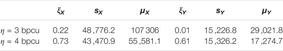
TABLE 3. PDF approximation parameters.
Therefore, UPEP can be calculated as in Eqs 31, 42, for the case of
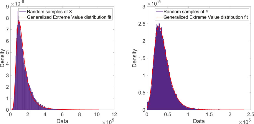
FIGURE 5. Distribution fit for variables X and Y.
4.2 Hybrid Beamforming Architecture
For this architecture, we assumed the same parameters with the analog architecture. Figure 6 shows the accuracy of our semi-analytical derivations. We considered scenarios with 3 and 4 bpcu spectral efficiency with 1 extra bit modulated by CIM. Table 2 shows detailed information at the selected M-ary constellation used for each case. As we can see, the derived semi-analytical expressions provide an upper bound for the BER. To achieve analytical results, we need to obtain the PDF of random variables
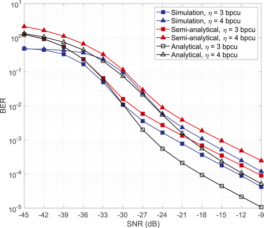
FIGURE 6. Theoretical and simulation performance comparison for hybrid architecture.
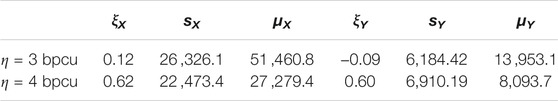
TABLE 4. PDF approximation parameters for the hybrid architecture.
In Figure 7, we show the superiority of the proposed scheme in hybrid architecture in comparison with the BIM structure proposed in (Mokh et al. (2019)). In the BIM structure, the dominant paths have been selected for indexing purposes. However, correlation among indexed paths can increase the BER. Hence, in the proposed CIM structure, dominant paths have been selected from the well separated clusters to decrease correlation among them. Simulation results illustrate BER for the spectral efficiency of 4 bpcu with 2 bits IM. We provide computer simulations for both BIM and CIM with different number of paths distributed uniformly in four clusters. As illustrated in Figure 7, when there are 4 paths in the environment, the performance of two schemes are identical because there is only one path in each cluster. However, with increasing the number of paths, the performance of CIM increases significantly, while BIM performs worse. This is because in BIM, indexed paths can be selected from the same clusters which leverage the huge correlation on the selected paths, while CIM guarantees that selected paths are far enough to decrease the effect of inter-beam interference. However, the improvement in the performance of CIM is not permanent with increasing the number of paths, and after a specific number of paths, it decreases. This is because with increasing number of paths, the transmitted signal experiences leakage on the neighboring paths, which decreases the effective transmitted power in the selected path.
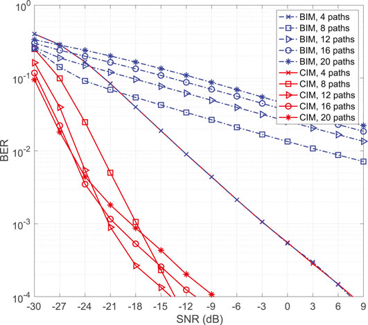
FIGURE 7. CIM and BIM performance comparison.
5 Conclusion
In this study, we have proposed a novel IM scheme for future mmWave communication systems, which takes into consideration well-separated clusters for indexing purpose. With adopting these separated clusters, the indexed paths become near orthogonal; hence, the inter-beam interference, which is one of the biggest problems in the mmWave communication, decreases significantly. Furthermore, we have studied the architecture of hybrid precoder and considered a ZF precoder at the transmitter to further suppress the inter-beam interference. With such an architecture, we have assumed and studied the system in more realistic conditions. Computer simulation results reveal that CIM can perform better than traditional mmWave communication, and hybrid CIM performs better than BIM in terms of BER. We derived semi-analytical and analytical error probability expression for the proposed scheme, which have proven the superiority of our scheme. Our future study might focus on multiuser systems with randomly distributed clusters in the mmWave communication environments to study scenarios under more realistic circumstances.
Data Availability Statement
The original contributions presented in the study are included in the article/Supplementary Materials; further inquiries can be directed to the corresponding author.
Author Contributions
MR performed computer simulations and analyses. MR and AK organized the manuscript. EB and TL-N supervised the study, proposed the initial concept, and reviewed the manuscript at certain stages.
Funding
The work of MR and EB was supported by the Scientific and Technological Research Council of Turkey (TUBITAK) under grant 218E035. The work of AK and TLN was supported in part by the Natural Sciences and Engineering Research Council of Canada (NSERC).
Conflict of Interest
The authors declare that the research was conducted in the absence of any commercial or financial relationships that could be construed as a potential conflict of interest.
Publisher’s Note
All claims expressed in this article are solely those of the authors and do not necessarily represent those of their affiliated organizations, or those of the publisher, the editors, and the reviewers. Any product that may be evaluated in this article, or claim that may be made by its manufacturer, is not guaranteed or endorsed by the publisher.
References
Akdeniz, M. R., Liu, Y., Samimi, M. K., Sun, S., Rangan, S., Rappaport, T. S., et al. (2014). Millimeter Wave Channel Modeling and Cellular Capacity Evaluation. IEEE J. Select. Areas Commun. 32, 1164–1179. doi:10.1109/jsac.2014.2328154
Ayach, O. E., Rajagopal, S., Abu-Surra, S., Pi, Z., and Heath, R. W. (2014). Spatially Sparse Precoding in Millimeter Wave MIMO Systems. IEEE Trans. Wireless Commun. 13, 1499–1513. doi:10.1109/twc.2014.011714.130846
Basar, E. (2016a). Index Modulation Techniques for 5G Wireless Networks. IEEE Commun. Mag. 54, 168–175. doi:10.1109/mcom.2016.7509396
Basar, E. (2016b). On Multiple-Input Multiple-Output OFDM with index Modulation for Next Generation Wireless Networks. IEEE Trans. Signal. Process. 64, 3868–3878. doi:10.1109/tsp.2016.2551687
Basar, E., Wen, M., Mesleh, R., Di Renzo, M., Xiao, Y., and Haas, H. (2017). Index Modulation Techniques for Next-Generation Wireless Networks. IEEE access 5, 16693–16746. doi:10.1109/access.2017.2737528
Ding, Y., Kim, K. J., Koike-Akino, T., Pajovic, M., Wang, P., and Orlik, P. (2017). Spatial Scattering Modulation for Uplink Millimeter-Wave Systems. IEEE Commun. Lett. 21, 1493–1496. doi:10.1109/lcomm.2017.2684126
Fan, Y., Gao, S., Cheng, X., and Yang, L. (2020). Pre-Compensation-Assisted Generalized Beam Index Modulation (PC-GBIM) for mmWave Massive MIMO over Doubly Selective Channels. IEEE Wireless Commun. Lett. 10, 411–415.
Gao, S., Cheng, X., and Yang, L. (2019). Spatial Multiplexing with Limited RF Chains: Generalized Beamspace Modulation (GBM) for mmWave Massive MIMO. IEEE J. Select. Areas Commun. 37, 2029–2039. doi:10.1109/jsac.2019.2929400
Heath, R. W., Gonzalez-Prelcic, N., Rangan, S., Roh, W., and Sayeed, A. M. (2016). An Overview of Signal Processing Techniques for Millimeter Wave MIMO Systems. IEEE J. Sel. Top. Signal. Process. 10, 436–453. doi:10.1109/jstsp.2016.2523924
Koc, A., and Le-Ngoc, T. (2021). Full-duplex Mmwave Massive Mimo Systems: A Joint Hybrid Precoding/combining and Self-Interference Cancellation Design. IEEE Open J. Commun. Soc. 2, 754–774. doi:10.1109/ojcoms.2021.3069672
Koc, A., Masmoudi, A., and Le-Ngoc, T. (2020). 3D Angular-Based Hybrid Precoding and User Grouping for Uniform Rectangular Arrays in Massive MU-MIMO Systems. IEEE Access 8, 84689–84712. doi:10.1109/access.2020.2992713
Li, H., Li, M., Liu, Q., and Swindlehurst, A. L. (2020). Dynamic Hybrid Beamforming with Low-Resolution PSs for Wideband mmWave MIMO-OFDM Systems. IEEE J. Select. Areas Commun. 38, 2168–2181. doi:10.1109/jsac.2020.3000878
Mokh, A., Shehata, M., Crussière, M., and Hélard, M. (2019). Analytical Performance of Hybrid Beam index Modulation. IEEE Wireless Commun. Lett.
Muraleedharan, G., Soares, C. G., and Lucas, C. (2011). “Characteristic and Moment Generating Functions of Generalised Extreme Value Distribution (GEV),” in Sea Level Rise, Coastal Engineering, Shorelines and Tides. Editors L. L. Wright (Hauppauge, New York: Nova Science Publishers), 269–276.
Niu, Y., Li, Y., Jin, D., Su, L., and Vasilakos, A. V. (2015). A Survey of Millimeter Wave Communications (mmWave) for 5G: Opportunities and Challenges. Wireless Netw. 21, 2657–2676. doi:10.1007/s11276-015-0942-z
Perović, N. S., Liu, P., Di Renzo, M., and Springer, A. (2016). Receive Spatial Modulation for LOS mmWave Communications Based on TX Beamforming. IEEE Commun. Lett. 21, 921–924. doi:10.1109/LCOMM.2016.2642923
Raafat, A., Yüzgeçcioğlu, M., Aslam, M. Z., Agustin, A., Vidal, J., Jorswieck, E., et al. “Energy Efficient Transmit-Receive Spatial Modulation for Uplink-Downlink Large-Scale MIMO Systems,” in 2018 IEEE Globecom Workshops (GC Wkshps) (IEEE), Abu Dhabi, UAE, December 2018, 1–6.
Rappaport, T. S., Heath, R. W., Daniels, R. C., and Murdock, J. N. (2015). Millimeter Wave Wireless Communications. London, United Kingdom: Pearson Education.
Sun, S., Rappaport, T., Heath, R., Nix, A., and Rangan, S. (2014). MIMO for Millimeter-Wave Wireless Communications: Beamforming, Spatial Multiplexing, or Both? IEEE Commun. Mag. 52, 110–121. doi:10.1109/mcom.2014.6979962
Wang, T., Ai, B., He, R., and Zhong, Z. (2015). Two-dimension Direction-Of-Arrival Estimation for Massive Mimo Systems. IEEE Access 3, 2122–2128. doi:10.1109/access.2015.2496944
Wang, W., and Zhang, W. (2019). Spatial Modulation for Uplink Multi-User mmWave MIMO Systems with Hybrid Structure. IEEE Trans. Commun. 68, 177–190. doi:10.1109/TCOMM.2019.2948340
Xiao, M., Mumtaz, S., Huang, Y., Dai, L., Li, Y., Matthaiou, M., et al. (2017). Millimeter Wave Communications for Future mobile Networks. IEEE J. Select. Areas Commun. 35, 1909–1935. doi:10.1109/jsac.2017.2719924
Ying, K., Gao, Z., Lyu, S., Wu, Y., Wang, H., and Alouini, M.-S. (2020). GMD-based Hybrid Beamforming for Large Reconfigurable Intelligent Surface Assisted Millimeter-Wave Massive MIMO. IEEE Access 8, 19530–19539. doi:10.1109/access.2020.2968456
Yu, X., Zhang, J., and Letaief, K. B. (2018). A Hardware-Efficient Analog Network Structure for Hybrid Precoding in Millimeter Wave Systems. IEEE J. Sel. Top. Signal. Process. 12, 282–297. doi:10.1109/jstsp.2018.2814009
Yüzgeçcioğlu, M., and Jorswieck, E. “Hybrid Beamforming with Spatial Modulation in Multi-User Massive MIMO mmWave Networks,” in Proceedings of the 2017 IEEE 28th Annual International Symposium on Personal, Indoor, and Mobile Radio Communications (PIMRC) (IEEE), Montreal, QC, Canada, October 2017, 1–6.
Zheng, Z., Wang, W.-Q., Meng, H., So, H. C., and Zhang, H. (2018). Efficient Beamspace-Based Algorithm for Two-Dimensional Doa Estimation of Incoherently Distributed Sources in Massive Mimo Systems. IEEE Trans. Veh. Technol. 67, 11776–11789. doi:10.1109/tvt.2018.2875023
Zhou, P., Cheng, K., Han, X., Fang, X., Fang, Y., He, R., et al. (2018). IEEE 802.11ay-Based mmWave WLANs: Design Challenges and Solutions. IEEE Commun. Surv. Tutorials 20, 1654–1681. doi:10.1109/comst.2018.2816920
Keywords: mmWave communications, index modulation, hybrid beamforming, bit error rate, zero-forcing
Citation: Raeisi M, Koc A, Basar E and Le-Ngoc T (2022) Cluster Index Modulation for mmWave Communication Systems. Front. Comms. Net 2:803007. doi: 10.3389/frcmn.2021.803007
Received: 27 October 2021; Accepted: 06 December 2021;
Published: 09 February 2022.
Edited by:
Abdulkadir Celik, King Abdullah University of Science and Technology, Saudi ArabiaReviewed by:
Yasin Kabalci, Niğde Ömer Halisdemir University, TurkeyMohammed Riyaz Ahmed, REVA University, India
Copyright © 2022 Raeisi, Koc, Basar and Le-Ngoc. This is an open-access article distributed under the terms of the Creative Commons Attribution License (CC BY). The use, distribution or reproduction in other forums is permitted, provided the original author(s) and the copyright owner(s) are credited and that the original publication in this journal is cited, in accordance with accepted academic practice. No use, distribution or reproduction is permitted which does not comply with these terms.
*Correspondence: Ertugrul Basar, ZWJhc2FyQGt1LmVkdS50cg==