
95% of researchers rate our articles as excellent or good
Learn more about the work of our research integrity team to safeguard the quality of each article we publish.
Find out more
ORIGINAL RESEARCH article
Front. Commun. Netw. , 11 November 2021
Sec. Wireless Communications
Volume 2 - 2021 | https://doi.org/10.3389/frcmn.2021.733698
 Debdeep Sarkar 1*
 Yahia Antar2
In this paper, we demonstrate the usefulness of MoM (Method-of-Moments) based methods in efficient path-loss modelling for SISO (single-input single-output) communication links assisted by IRS (Intelligent Reflecting Surfaces). Being a full-wave computational electromagnetic tool, MoM is better equipped compared to high-frequency asymptotic methods like PO (Physical Optics), to handle the crucial electromagnetic (EM) effects like: mutual coupling between IRS unit-cells or interactions with spherical wave-front in antenna near-field. Furthermore, in terms of computational speed, accuracy and reproducibility, the MoM-based MATLAB Antenna Toolbox is significantly advantageous to emulate IRS-assisted wireless channels, as compared to the in-house FDTD (finite-difference time-domain) techniques. We consider a SISO system of two half-wavelength dipoles, and use a rectangular array of circular loops loaded with lumped circuit components as IRS. The lumped circuit loading enables us to control the reactance of individual unit-cells, resulting in alteration of IRS reflection coefficient and consequent changes in channel characteristics. Using numerous numerical simulations, we highlight the impacts of various IRS-parameters like: electrical size and number of unit-cells, distance of IRS from the transmitter/receiver as well as mutual coupling, on the path-loss models (both sub-6 GHz and mm-wave).
The concept of deploying IRS (intelligent reflecting surfaces) in the environment (eg. the walls of buildings) is becoming extremely popular, for its potential in leading to enhanced data rate, extended coverage, minimized power consumption, and more secure transmission (Björnson et al., 2020), Björnson and Sanguinetti (2020), (Di Renzo et al., 2020). Generally in an IRS, one uses a frequency selective surface (FSS) or “meta-surface,” i.e. large two-dimensional array of passive scattering elements (or unit-cells), and performs joint phase control of all these IRS unit cells through external software control. Typically, the purpose of using an IRS is to reflect an incoming wave from a far-field source towards a receiver in the far-field (Björnson et al., 2020), Björnson and Sanguinetti (2020), (Di Renzo et al., 2020). By arbitrarily tuning the reflecting phase and angles of the incident RF signals, the received signal power can boosted by coherent addition for some UEs. In some scenarios, unwanted cross-talk between different UEs can also be mitigated by destructive interference.
To design and predict the performance of any IRS-based communication system, it is critical to derive accurate path-loss models, and perform a holistic characterization of the IRS-assisted channels. Several works are being carried out in this regard, which either involve quasi-analytical methods based on certain assumptions about the propagating waves and their interactions with the IRS unit-cells, or use PO/GO (Physical Optics and Geometrical/Ray Optics) based tools (Ozdogan et al., 2020), (Najafi et al., 2021). In PO/GO based analysis, the size of the IRS is considered to be crucial in shaping the beam-width of the reflected beam and very often the IRS is modelled as an array of diffuse scatterers. The IRS unit-cells (or “tiles”) are considered to be “anomalous reflectors,” and the response functions are calculated by assuming the plane-wave incidence approach (Ozdogan et al., 2020), (Najafi et al., 2021). The overall impact of the IRS on the wireless channel is determined for a given phase shift, after solving the corresponding integral equations for the corresponding electromagnetic fields (Najafi et al., 2021).
While all these approaches are definitely judicious and useful, several crucial electromagnetic interactions in IRS-assisted communication links are often neglected, like:
• Dispersive nature: the reflective properties of IRS will be dependent on the operating frequency, which may be critical for broadband communication perspective;
• Lack of angular stability: the IRS properties will get altered for electromagnetic (EM) waves impinging from different incident angles, and polarizations (Transverse electric or magnetic);
• Illumination from near-field sources: If the transmitter or receiver are not present sufficiently distant (electrically) from the IRS, the field impinging upon the IRS will have spherical wave-fronts which are generated in the near-field radiating regime of antennas. Therefore the reflective properties from the IRS will be considerably changed, as plane-wave incidence criterion is no longer satisfied in such cases. It is not possible to handle this phenomenon using traditional ray-tracing (RT) or GO1.
• Mutual Coupling between unit-cells: Generally, asymptotic techniques like PO or UTD (Uniform Theory of Diffractions) are deployed for analyzing EM wave interactions with electrically large systems (eg. ships, aircrafts, etc). But PO based techniques can not efficiently characterize the finer EM effects caused by the mutual coupling between the unit-cells comprising the IRS structure Davidson (2010).
Therefore, it has become extremely important to apply full-wave computational electromagnetic (CEM) tools like FDTD (Finite-Difference Time-Domain Methods) or MoM (Method of Moments) to properly characterize the effect of IRS in a wireless network, specially when the IRS might not be electrically very large, or placed too far away from the transmitters/receivers. Borrowing the idea from FDTD-based indoor channel modelling approaches (Sarkar et al., 2020), critically examines the effect of IRS based on reconfigurable thin-wire type FSS on a line-of-sight (LOS) massive-MIMO communication link, by observing the singular values of the channel matrix for various switching states in the IRS.
In this article, we are focusing on a different CEM technique: the MoM (Method of Moments) to analyze SISO (single-input single-output) communication links. Instead writing a MoM code from scratch, we deploy the commercially available MoM based MATLAB Antenna Toolbox for our simulation purpose. The inherent advantages of using a MoM based simulation paradigm are as follows:
1) Being a full-wave simulation scheme, MoM-based approach allows us to properly account for the near-field interaction and mutual coupling effects, unlike the asymptotic PO or GO based Davidson (2010).
2) The computation time and memory requirement in MoM is drastically less compared to FDTD (Sarkar et al., 2020), therefore there is scope of generating high-volume of datasets and optimize IRS topologies for a given transmitter-receiver arrangement using artificial intelligence or machine learning techniques.
3) Since the entire structure is coded using MATLAB Antenna Toolbox, the results are easily reproducible, rendering the approach more suitable compared to complex in-house FDTD simulation codes.
However, while FDTD can handle a wide-range of dielectric materials, for MoM one has to primarily handle conducting materials and wire-type structures, which can be interpreted as a disadvantage. But even with these limitations, it is possible to implement a reasonably wide-range of practical antenna systems and IRS-topologies, and generate useful channel modelling data using MoM. In the subsequent section, we will demonstrate the simulation of IRS-assisted SISO links based on two dipoles, and an IRS implemented by an array of circular-loops (often referred to as split-ring resonators or SRRs in metamaterial terminology).
Figure 1 shows the schematic diagram of a simple transmit-receive SISO communication link using two dipoles separated by a distance d. The length of each dipole is chosen as 0.47λ to ensure near-zero input reactance for the dipoles, where λ = c/f0, f0 = 3.5 GHz (sub-6 GHz 5G range) being the operating frequency chosen for all simulations, and c = 3 × 10⁸ m/s is the speed of light. To modulate the channel properties, an IRS comprising of N × N array of PEC (perfect electric conductor) loop unit-cells is placed at a distance of s from the transmitting dipole (see Figure 1). One key underlying idea behind the use of IRS near the transmitter, is to control the channel propagation characteristics through the properties of the IRS-unit cells, i.e. the circular PEC loops in our case. The resonant frequency and operating modes of the individual PEC loops are controlled by the radius r of each PEC loop, along with the lumped circuit load ZLoad placed on each loop (see Figure 1). The mutual coupling between the loops are controlled by the center-to-center spacing p between the loops. Note that the PEC loops are essentially thin-wire strips, therefore the width of the strips is kept very small (≈0.01λ). Also, the value of p is fixed as 2r + 2 mm, for the subsequent simulations. Now, note that the total input impedance Zin,L of each loop can be expressed as:
where Zin,UL is the loop input-impedance without any lumped circuit loading, that provides an impedance ZLoad in the series. For most simulations we keep:
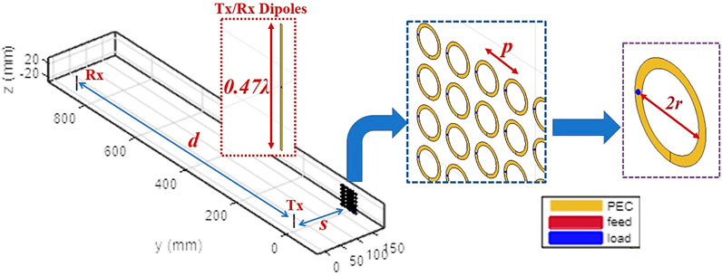
FIGURE 1. Schematic diagram of IRS-assisted SISO communication link using two dipoles (each 0.47λ long), realized using MATLAB Antenna Toolbox. The IRS placed near the transmitter comprises of N × N array of circular loops, each of radius r.
To estimate the impact of the IRS on the path-loss, we define a metric ΔP (in dB) as follows:
where
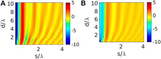
FIGURE 2. Variation of ΔP (in dB) for the configuration in Figure 1 with respect to d/λ and s/λ, keeping p =2r +2 mm for: (A) N =4, r =0.1λ, (B) N =8, r =0.05λ.
Figure 2 depicts that for similar physical area of IRS and same distance ranges (i.e. d/λ and s/λ values), the IRS having the loop unit-cell dimensions such that the circumference is closer to the loop self-resonance at half-wavelength, provides greater variations in the path-loss distribution. Overall, incorporation of IRS has enhanced the received signal level at the receiver (ΔP > 0 dB in most regions). However, greater values of ΔP has been achieved for same d/λ and s/λ values, depending on the loop-size, even when the physical IRS area is roughly of the same order. We can infer that unit-cell choice for IRS has to be carefully done, so that they can interact effectively with the impinging electromagnetic waves in a resonant manner; depending on the unit-cell dimensions and operating modes, currents will be induced in the IRS, leading to reflection properties. Note that, the sub-wavelength loops (i.e. with r = 0.05λ) did not have the same interaction with the impinging signals from the transmitter, as compared to their counter parts having r = 0.1λ. This control-feature based on unit-cell shape and dimensions also demonstrates how an IRS differs from a simple continuous passive PEC plate placed near the transmitter or receiver. We further study the impact of unit-cell size, keeping the value of N fixed at 4 (see Figure 3). When the loop radius is increased to 0.2λ, the loop perimeter 2πr becomes more than λ, thereby leading to a different operating mode for the same excitation frequency. Therefore, the scattering features of the entire IRS i.e. array of circular loops get altered, leading to distinct change in the ΔP distribution pattern. Clearly, larger loop-radius leads to higher increase in ΔP for greater s/λ value, when the same d/λ is kept at same level (see Figure 3). Therefore, the IRS can be kept farther way from the transmitter, and same path-loss compensation can be achieved by increasing the IRS unit-cell dimensions from sub-wavelength scale to larger values.
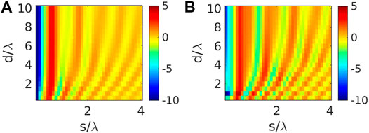
FIGURE 3. Variation of ΔP (in dB) for the configuration in Figure 1 with respect to d/λ and s/λ considering 4×4 array of loops as the IRS, with: (A) r =0.1λ, (B) r =0.2λ. Here p =2r +2 mm.
While it is possible to change the reflection/scattering from IRS by changing the size (and consequently the resonant operating modes) of the unit cells, it can not be carried out “real-time” (i.e. using external electronic control signals). One key usefulness of IRS lies in the possibility to tailor the reflection/scattering by varying the lumped circuit loading of the individual IRS unit cells. So far we simply used the ZLoad value to cancel out the input reactance of each loops, but now we focus on varying ZLoad of each unit cell, which alters the ΔP (in dB) distribution (see Figure 4). Practically, this variation in ZLoad (both resistance and reactive parts) can be achieved by using circuit components like Varactor diodes, as well as transistor-based voltage controlled resistor elements. Note that, increasing the resistance value of the input impedance, simply implies that the loop is approaching more towards an open circuit termination condition. However, due to limitations in MATLAB Antenna Toolbox, it was not possible to incorporate negative resistance values to realise an short-circuit termination, especially for the loops having r = 0.1λ having a finite input resistance close to 97 Ω. But, it is indeed possible to provide both inductive and capacitive reactive loads, and it can be seen that the path loss behaviour is significantly changed (Figure 4). In our case, the inductive reactance condition of individual loops appear to be causing a greater path loss compensation as compared to the capacitive reactance condition (Figure 4C and Figure 4D).
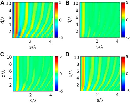
FIGURE 4. Variation of ΔP (in dB) considering 4×4 IRS near Tx-dipole (see Figure 1), considering the input impedance Zin,L for individual loops as: (A) 96.57 + j0 Ω, (B) 2096.57 + j0 Ω, (C) 96.57–j865.30 Ω, (D) (c) 96.57 + j865.30 Ω. We keep r =0.1λ and p =2r +2 mm.
Next we consider the impact of IRS location with respect to the transmit and receive dipoles, and compute the corresponding ΔP distributions by varying the loop-radius as well as the individual loop loading through ZLoad. A symmetric configuration is considered (see Figure 5), where the IRS is located at same distance from both transmitting and receiving dipole. Increasing r while keeping N same has the similar qualitative effect as that of the previous asymmetric case (i.e. IRS near the transmitter), but the range of values for ΔP has changed (Figure 5B and Figure 5C). Same observation is valid for the scenarios having different load values in the IRS unit cells (see Figure 6). These analyses based on IRS locations emphasize upon the importance of generating such ΔP variation curves for different IRS locations for same Tx-Rx antenna setup, because the channel properties change drastically with it and it is not possible to make a very general statement.
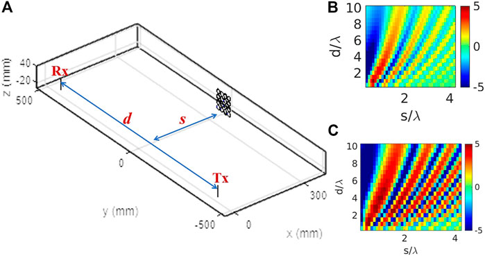
FIGURE 5. (A) Schematic diagram of alternative IRS-assisted SISO communication link using two 0.47λ long dipoles, realized using MATLAB Antenna Toolbox. The IRS is kept symmetrically with respect to both Tx and Rx-dipoles, at a distance s from the path connecting the dipoles. The corresponding variations of ΔP (in dB) with respect to s/λ and d/λ, considering: (B) r =0.1λ, (C) r =0.2λ. Here p =2r +2 mm.
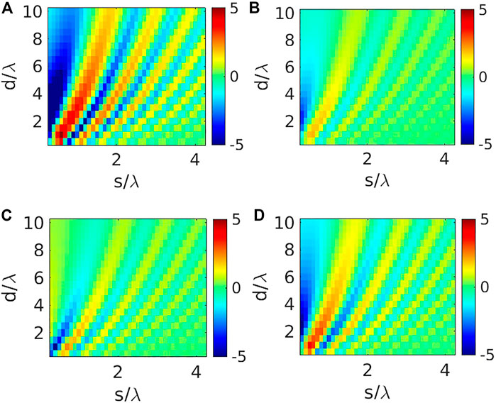
FIGURE 6. Variation of ΔP (in dB) considering 4×4 IRS near Tx-dipole (see Figure 5), considering the input impedance Zin,L for individual loops as: (A) 96.57 + j0 Ω, (B) 2096.57 + j0 Ω, (C) 96.57–j865.30 Ω, (D) (c) 96.57 + j865.30 Ω. We keep r =0.1λ and p =2r +2 mm.
Finally we demonstrate the role of the mutual coupling between the unit cells, in governing the path loss pattern. We consider the 4 × 4 IRS with r = 0.1λ, but consider the IRS placement to be both asymmetric and symmetric, keeping s = 0.5λ for both cases. To make a proper, comparison we first keep the value of |S21| for p = 2r + 2 mm as reference i.e.
It can be noticed from the ΔG plots that the symmetric arrangement in Figure 7B is more prone to the mutual coupling effects as compared to the asymmetric case of Figure 7A, especially when the IRS is placed close to the transmitter. However, even for the symmetric arrangement, when we consider the IRS to be placed at greater distance 5λ (see Figure 7C), the impact of mutual coupling on the ΔG subsides significantly.
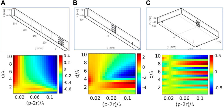
FIGURE 7. Effect of mutual coupling between IRS unit-cells upon the distribution of ΔG: (A) s =0.5λ for configuration in Figure 1B s =0.5λ for configuration in Figure 5C s =5λ for configuration in Figure 5.
It should be remembered that communication links operating in sub-6 GHz are not sensitive to blockages when compared to mm-wave signals. Therefore, we extend our MoM based simulation approach to analyse SISO links working at 28 GHz. We use half-wavelength dipoles as both transmitter (Tx) and receiver (Rx) separated by distance d, and the IRS is placed at a distance s from the transmitter as shown in Figure 8. The loop radius values are appropriately scaled with respect to λ, so that the IRS operates in the 28 GHz frequency band. Figure 8 demonstrates the path-loss variations with respect to both Tx-Rx and Tx-IRS distances (i.e. s/λ and d/λ).
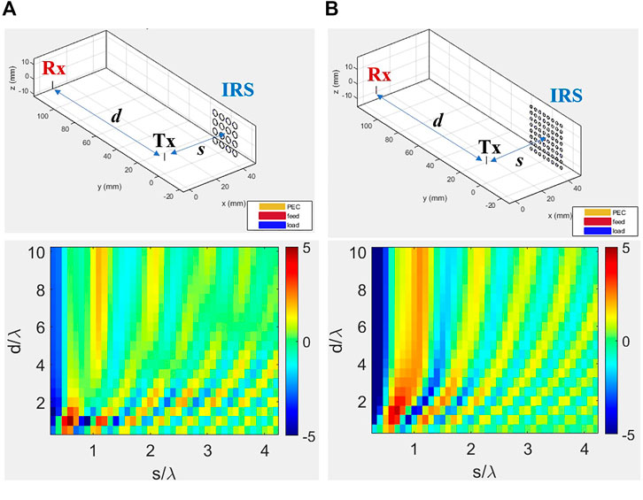
FIGURE 8. Variation of ΔP (in dB) with respect to d/λ and s/λ for two IRS-assisted SISO Comm-links operating at 28 GHz: (A) N =4, r =0.2λ, (B) N =8, r =0.1λ. For both, we keep keeping p =2r +2 mm (see Figure 1).
It can be observed that the qualitative nature of the two-dimensional ΔP distributions are similar to the ones observed for the sub-6 GHz frequency range. Clearly, the variation in path-loss is quite sensitive to the s/λ, i.e. the distance between the Tx and the IRS. The value of ΔP appears to be oscillating between maximum and minimum values (i.e.). Also, the area of the IRS plays a significant role in shaping the path-loss variation, especially for lower Tx-IRS distances. One can say that to achieve a considerable impact on the pathloss variation with smaller IRS unit-cell size, one has to increase the IRS array (see that the 8 × 8 loop-array based IRS with loop-radius 0.1λ gives very prominent effect on ΔP for lower s/λ values.)
Although the dipole antennas are inherently narrowband structures, it is vital to study their interactions over a wide frequency band, instead of concentrating on the single 28 GHz frequency. We first analyse the variation of PL = S21 of the Tx-Rx system by keeping the separation d at 10λ (Figure 9A), and varying frequency range from 20–40 GHz. As anticipated, the maximum transmission from Tx-to-Rx can be observed near 28 GHz, i.e. dipole impedance match frequency. But overall there is significant wireless power transfer in the 25–30 GHz frequency range (Figure 9B). After that, we place the IRS (8 × 8 array of loops having radius 0.2λ) at a distance 1.5λ away from the Tx. Figure 9B shows that as the IRS size is increased, greater enhancement of ΔP is observed within the entire frequency range 25–30 GHz. Therefore it is once again reaffirmed that IRS size is a critical factor in governing modifying the pathloss characteristics in IRS assisted communication links. Since the operating mechanism of such IRS is quite similar to classical reflectarray antenna systems, it can be intuitively inferred that the IRS aperture area will play a major role in focusing of reflected power at a desired location; since greater aperture area translates into higher gain in reflectarrays, it is natural that ΔP will increase in presence of larger IRS sizes.
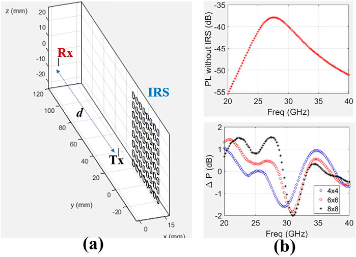
FIGURE 9. (A) Schematic diagram of SISO Link comprising of a Tx and Rx dipole placed 10λ away from each other, with 8×8 Loop-array as IRS placed 1.5λ away from the Tx-dipole. (B) Top figure shows the Frequency variation of path-loss i.e. S21 for the Tx-Rx system without IRS
Finally, the underlying advantages of using MoM simulation to achieve insights into the finer details of spatial path-loss variation for IRS-assisted Comm-links are demonstrated by comparing with the theoretical bounds provided in Ozdogan et al. (2020). Figure 10A shows the schematic of a SISO Tx-Rx system separated by distance d, with an IRS of area AIRS spaced at a distance s. Since the IRS is an N × N array of circular loops having radius r and center-to-center spacing p, the value of AIRS can be obtained as:
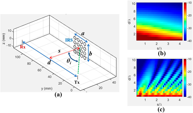
FIGURE 10. (A) Schematic diagram of a Dipole-based Tx-Rx system (separation d) operating at 28 GHz. An IRS having 4×4 configuration of loops (r =0.2λ and p =2r +2 mm) is placed at a distance s as shown. Two-dimensional distribution of path-loss i.e. S21 for different s/λ and d/λ calculated using: (B) Theoretical formula from Ozdogan et al. (2020) i.e. PLtheory, (C) MoM simulations using proposed approach, i.e.
Following equation (19) of Ozdogan et al. (2020), the theoretical bounds on the path-loss can be obtained for the proposed configuration of Figure 10A as:
We also numerically compute the
It is crucial to note that, the theoretical upper bound will assist designers to get an initial guess about how the pathloss will vary for different Tx-Rx and Tx-IRS distances. Note that, the theoretical bound is mainly computed from Friis transmission equation viewpoint and assuming interaction between Tx Rx and IRS via plane wavefronts. However, for radiating near-field regions, it is important to consider the impacts of spherical wavefronts. Therefore, the periodic “ripple-like” variations in the pathloss, especially for varying s/λ while keeping d/λ fixed, are better captured using the full-wave MoM approach (see HYPERLINK Figure 10B and HYPERLINK Figure 10C).
In this paper, we illustrate the effectiveness of MoM-based MATLAB Antenna toolbox in characterization of path-loss models for IRS-assisted communication links. The importance of different parameters like unit-cell size, overall IRS dimension, placement of IRS with respect to transmitter/receiver and mutual coupling between individual unit-cells are critically examined, in the context of path-loss model estimation. We perform simulations for different set of distances between the transmitter and receiver, encompassing both near-field and far-field regimes. While the analysis is done for a SISO link, it can be extended for MIMO links in MATLAB Antenna Toolbox, through straightforward process. Further note that, for simplicity of simulation, we simultaneously varied all the ZLoad values to similar values. While it is possible in the MATLAB Antenna Toolbox platform to perform simulations by changing individual ZLoad values, but in that case it is not possible to define the IRS as an linear or rectangular array of loops.
The key takeaways from the detailed MoM simulation studies are summarized below:
1) It is demonstrated that IRS unit-cell size can be increased and one does not have to necessarily stick to “Metasurfaces” (where the unit-cells are working in the subwavelength regime). We show from numerical simulations that IRS with larger unit-cell size can also support resonant operating modes leading to reflection characteristics leading to controllable pathloss variation. This potentially paves the way for designing multifunctional IRS using electrically large resonators or travelling wave/leaky wave structures to achieve a certain scattering performance that would eventually lead to a desired pathloss.
2) The full wave MoM simulations reaffirm earlier theoretical and PO/GO based studies that the overall IRS area and location of IRS with respect to the transmit-receive system play the crucial role in governing the pathloss variation. The design curves obtained for both sub-6 and 28 GHz frequency ranges provide a general trend, which confirms scalability of the IRS based approach.
3) The effect of mutual coupling between IRS unit cells is also critically studied. It was shown that the effect of mutual coupling between IRS unit cells only matter if the spacing between IRS and the transceiver system is less.
4) While the theoretical upper bounds definitely give a rough initial idea about the effects of Tx-Rx separation and distance of IRS on the pathloss, the proposed MoM based approach has better ability to predict the periodically varying nature of pathloss, when the distance of the IRS from the Tx-Rx assembly is gradually increased. This is clearly due to the better ability of full-wave MoM based method to capture the spherical wavefront effects via full wave EM simulations. Therefore, a judicious combination of the theoretical approaches, coupled with full wave EM simulations will eventually engineers to design IRS assisted wireless communication links.
In future works, We will also explore possibility of incorporating dielectric structures or metal-plate scatterers in the MoM-based paradigm, and study the relevant effects on the IRS-assisted wireless channels.
The raw data supporting the conclusions of this article will be made available by the authors, without undue reservation.
This work is done by mutual discussion among both the authors (DS and YA). The simulation results and corresponding interpretations are contributed by both the authors.
One of the authors, DS is thankful to the “Young Investigator grant” endowed by Infosys Foundation, Bangalore R(HR)Infosys-YI/2020-854/99 for supporting this research through partial funding.
The authors declare that the research was conducted in the absence of any commercial or financial relationships that could be construed as a potential conflict of interest.
All claims expressed in this article are solely those of the authors and do not necessarily represent those of their affiliated organizations, or those of the publisher, the editors and the reviewers. Any product that may be evaluated in this article, or claim that may be made by its manufacturer, is not guaranteed or endorsed by the publisher.
1A metasurface is often considered to a “specular reflector” according to geometrical optics, which essentially assumes plane-wave incidence.
Björnson, E., Ozdogan, O., and Larsson, E. G. (2020). Intelligent Reflecting Surface versus Decode-And-Forward: How Large Surfaces Are Needed to Beat Relaying? IEEE Wireless Commun. Lett. 9, 244–248. doi:10.1109/LWC.2019.2950624
Björnson, E., and Sanguinetti, L. (2020). Power Scaling Laws and Near-Field Behaviors of Massive Mimo and Intelligent Reflecting Surfaces. IEEE Open J. Commun. Soc. 1, 1306–1324. doi:10.1109/OJCOMS.2020.3020925
Davidson, D. B. (2010). Computational Electromagnetics for RF and Microwave Engineering. 2nd edition. Cambridge, United Kingdom: Cambridge University Press.
Di Renzo, M., Zappone, A., Debbah, M., Alouini, M.-S., Yuen, C., de Rosny, J., et al. (2020). Smart Radio Environments Empowered by Reconfigurable Intelligent Surfaces: How it Works, State of Research, and the Road Ahead. IEEE J. Select. Areas Commun. 38, 2450–2525. doi:10.1109/JSAC.2020.3007211
Najafi, M., Jamali, V., Schober, R., and Poor, H. V. (2021). Physics-based Modeling and Scalable Optimization of Large Intelligent Reflecting Surfaces. IEEE Trans. Commun. 69, 2673–2691. doi:10.1109/TCOMM.2020.3047098
Ozdogan, O., Björnson, E., and Larsson, E. G. (2020). Intelligent Reflecting Surfaces: Physics, Propagation, and Pathloss Modeling. IEEE Wireless Commun. Lett. 9, 581–585. doi:10.1109/lwc.2019.2960779
Sarkar, D., Mikki, S., and Antar, Y. (2020). “An Electromagnetic Framework for the Deployment of Reconfigurable Intelligent Surfaces to Control Massive Mimo Channel Characteristics,” in 2020 14th European Conference on Antennas and Propagation (Copenhagen, Denmark: EuCAP)), 1–4. doi:10.23919/EuCAP48036.2020.9135824
Keywords: intelligent reflecting surface, method of moment, path loss, mutual coupling, SISO
Citation: Sarkar D and Antar Y (2021) Electromagnetic Insights Into Path Loss Modelling of IRS-Assisted SISO Links: Method-Of-Moment Based Analysis. Front. Comms. Net 2:733698. doi: 10.3389/frcmn.2021.733698
Received: 30 June 2021; Accepted: 28 September 2021;
Published: 11 November 2021.
Edited by:
Anas Chaaban, University of British Columbia Okanagan, CanadaReviewed by:
Hong Shen, Southeast University, ChinaCopyright © 2021 Sarkar and Antar. This is an open-access article distributed under the terms of the Creative Commons Attribution License (CC BY). The use, distribution or reproduction in other forums is permitted, provided the original author(s) and the copyright owner(s) are credited and that the original publication in this journal is cited, in accordance with accepted academic practice. No use, distribution or reproduction is permitted which does not comply with these terms.
*Correspondence: Debdeep Sarkar , ZGViZGVlcEBpaXNjLmFjLmlu
Disclaimer: All claims expressed in this article are solely those of the authors and do not necessarily represent those of their affiliated organizations, or those of the publisher, the editors and the reviewers. Any product that may be evaluated in this article or claim that may be made by its manufacturer is not guaranteed or endorsed by the publisher.
Research integrity at Frontiers
Learn more about the work of our research integrity team to safeguard the quality of each article we publish.