 Yichuan Li
 Salman Ghafoor
 Muhammad Fasih Uddin Butt
 Mohammed El-Hajjar
94% of researchers rate our articles as excellent or good
Learn more about the work of our research integrity team to safeguard the quality of each article we publish.
Find out more
ORIGINAL RESEARCH article
Front. Commun. Netw., 31 August 2021
Sec. Wireless Communications
Volume 2 - 2021 | https://doi.org/10.3389/frcmn.2021.725976
This article is part of the Research TopicResource Allocation in Cloud-Radio Access Networks and Fog-Radio Access Networks for B5G SystemsView all 5 articles
Given the increasing demand for high data-rate, high-performance wireless communications services, the demand on the radio access networks (RAN) has been increasing significantly, where optical fiber has been widely used both for the backhaul and fronthaul. Additionally, advances in signal processing such as multiple-input multiple-output (MIMO) techniques, have improved the performance as well as transmission rate of communications networks. Beamforming has been used as an efficient MIMO technique for providing a signal to noise ratio (SNR) gain as well as reducing the multi-user interference. However, beamforming requires the employment of phase-shifters, which suffers from reduced phase resolutions, degraded noise figures as well as beam-squinting in addition to the implementation challenges. Hence, in this paper we employ an analogue radio over fiber (A-RoF) aided architecture for supporting the requirements of the current and future mobile networks, where we design a photonics aided beamforming technique in order to eliminate the bulky electronic phase-shifters and the beam-squinting effect, while also providing a low-cost RAN solution. Additionally, this photonics aided beamforming is combined with a reconfigurable multi-user MIMO technique, where users can communicate with one or multiple remote radio heads (RRHs), while employing stand-alone beamforming, beamforming combined with diversity or with multiplexing depending on the available resources and the user channel information as well as the quality of service requirements.
The United Nation’s Sustainable Development Goals (UN SDGs) include 17 goals in the Agenda 2030, which are framed to address global challenges including climate change, poverty and inequality (UN2, 2015; 6G Flagship White paper, 2020). On the other hand, wireless communications has played a key role in creating the world as we know it, with its enormous social, environmental and economical impact, and its links with the UN SDGs are numerous (6G Flagship White paper, 2020).
The radio access network (RAN), which bridges the terminals to the core network, requires significant cost in order to support the growing demand for high data rate applications (Goldsmith, 2005; Hanzo et al., 2012; Checko et al., 2015). The RAN evolved significantly over the past decade. For example, in the fourth Generation (4G) mobile network, the concept of centralised RANs (C-RAN) was employed, where the central unit (CU) employs several baseband units (BBUs) connected to several remote radio heads (RRHs) by fiber. In this case, each RRH supports an individual cell (Li et al., 2020 (accepted). Then, in the fifth Generation (5G) mobile network, the RAN relocated some functions of the CU to the distribution unit (DU), flexibly supporting all use-cases, while some physical layer functions were moved to the RRH connected by radio over fiber (RoF) links [Li et al., 2020 (accepted)]. Furthermore, in order to have a decent quality of service, a large number of base-stations must be deployed, which increases the total cost of the RANs and hence ultra-light RANs are required (Checko et al., 2015).
Generally, the frequency, space, time, code and polarisation domains can be exploited as the available degrees of freedom for supporting a multiplicity of users (Goldsmith, 2005). Multiple-input Multiple-output (MIMO) techniques have been proposed for improving the performance as well as data rate of communications systems (Hanzo et al., 2011; Hemadeh et al., 2018). Explicitly, beamforming is a MIMO technique designed to attain an improved signal to noise ratio (SNR) gain and/or to reduce the inter-user interference of multi-user scenarios (Blogh and Hanzo, 2002; Hanzo et al., 2011; Satyanarayana et al., 2019). Beamforming is achieved by focusing the transmitted and/or received beam in the direction of the transmitter or receiver (Huang and Guo, 2011). On the other hand, MIMO techniques can be used to improve the system performance using diversity schemes, to increase the throughput using multiplexing schemes or to attain a combination of diversity, multiplexing and beamforming gains using the concept of multi-functional MIMO (Hanzo et al., 2011; Hemadeh et al., 2018). Additionally, the family of spatial modulation (SM) received significant research attention as detailed in (Ishikawa et al., 2018; Dogan-Tusha et al., 2020) for its reduced-complexity processing at both the transmitter and the receiver.
Additionally, it is worth noting that beamforming requires the employment of phase-shifters (Cao et al., 2016), which suffers from reduced phase resolutions, degraded noise figures as well as beam-squinting in addition to the implementation challenges such as the synchronization of the phase shifters (Poon and Taghivand, 2012; Zhang et al., 2018). The phase-shifter based beamforming results in the beam-squinting phenomenon, which is expected to be more severe when employing wide-band signal beam steering (Cao et al., 2016). Note that beam-squinting is the beam-shifts caused by the frequency shifts when applied with the constant phase-shift among neighbouring antenna elements (AE). Beam-squinting can affect the codebook design in the phased-array systems, which limits the bandwidth and the number of antennas (Cai et al., 2016). Additionally, beam-squinting affects the channel estimation and the precoding design, which results in a degraded performance (Wang et al., 2019).
The analogue radio over fiber (A-RoF) based true-time delay is a low-cost, high-performance RAN solution with ultra-light RRHs [Li et al., 2017; Li et al., 2018a; Li et al., 2018b; Li et al., 2020 (accepted)]. Explicitly, the A-RoF aided beamformer has been proposed for providing beam-squinting free solution with the aid of the uniform fiber Bragg grating (FBG) (Molony et al., 1996; Cao et al., 2016) or a single chirped FBG (CFBG) (Yao et al., 2002; Hunter et al., 2006).
In (Cao et al., 2016) a review of the integration techniques for the mmWave beamforming is provided, while focusing on the integration techniques rather than on their applications. Then, in (Li et al., 2018a) the spatial modulation and multi-set space-time shift-keying were optically processed and implemented in the A-RoF aided C-RAN system, while in (Li et al., 2018b) the twin-antenna spatial modulation was experimentally demonstrated. Furthermore, in (Li et al., 2017) the analogue beamforming using the optical aided true-time-delay was implemented in an indoor environment over the plastic optical fiber, while in (Molony et al., 1996) the phased-array antenna using the uniform fiber Bragg grating was presented, while having very limited tunability. In (Cao et al., 2016; Li et al., 2018a; Li et al., 2018b; Molony et al., 1996) the feasibility of A-RoF aided beamforming or MIMO is validated, inspiring more wireless applications. Hence, in this treatise, we propose a tunable optical aided true-time delay (TTD) beamforming system for supporting multi-user MIMO communications in a C-RAN environment.
In this article, we propose a low cost optical aided beamforming design using A-RoF aided C-RAN architecture to support multiple users. Additionally, we propose an reconfigurable multi-user MIMO scheme utilising the proposed beamforming technique. Explicitly, users can communicate with one or multiple RRHs, while employing standalone beamforming, beamforming combined with diversity or with multiplexing depending on the available resources and the user channel information as well as the quality of service requirements. More specifically, after performing user association, the CU collects all information about the user association with RRHs, the user channel state information and quality of service requirements. Then, the CU will decide on the transmission scheme for each user, which can be using beamforming or beamforming combined with diversity or multiplexing techniques. Then, using optical processing the beamforming is implemented, in order to eliminate the need for phase shifters at the RRH. Hence, in the proposed architecture, no signal processing is performed at the RRHs. Against this background, the novel contributions of our system can be summarized as follow:
1. We conceive an analogue radio over fiber aided multi-user beamforming system, where the CU is capable of controlling the beam direction, which is used to facilitate the different wireless transmission modes.
2. The proposed optical aided beamforming design can support multi-beam system with the aid of the wavelength division multiplexing techniques, where an all-optical signal processing based beam steering is achieved.
3. Finally, given that the user equipment can communicate with one or multiple RRHs, we present a reconfigurable multi-user MIMO technique, supported by the proposed beamforming combined with diversity or multiplexing.
The remainder of this paper is organized as follows. In Section 2 we present an overview of the C-RAN aided multi-user MIMO system model followed by our proposed multi-user reconfigurable MIMO system employing a novel optical aided beamforming technique in Section 3. Afterwards, we present our results and analysis in Section 4 and finally we present our conclusions in Section 5.
In this section, we present a general architecture for the C-RAN system supporting multi-user MIMO communications, which can be exploited in our design. As shown in Figure 1, the signal is generated in the CU and transmitted via fiber to several RRHs, where only optical-to-electronic conversion, amplification and filtering are performed. This substantially reduces the RRH size and cost. Explicitly, the RRH receives the signal from the CU using fiber and then transmits this signal to the user equipment using a set of antenna arrays, as shown in Figure 1, where a user equipment can be associated with one or more RRHs. In the following, we present an overview of conventional RoF-aided system followed by a background description of the optical aided beamforming, while we describe our proposed novel design in Section 3.
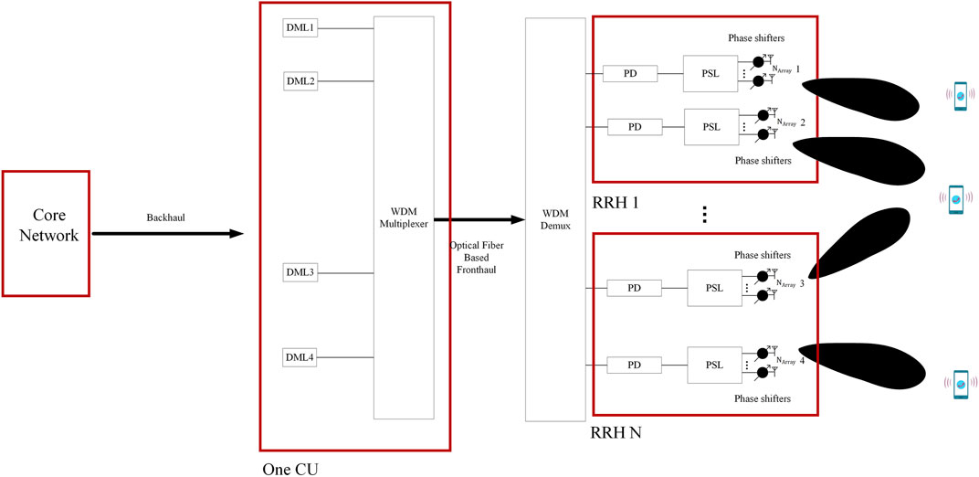
FIGURE 1. Conventional system model. (PSL: Power Splitter, DML: Directly Modulated Laser, WDM: Wavelength Division Multiplexing, CU: Central Unit, RRH: Remote Radio Head, PD: Photo-detector).
Conventionally, the A-RoF aided system can be supported using the architecture of Figure 1, where a number of directly modulated lasers (DMLs) are used for electronic-to-optical (E/O) conversion, which are then combined by the wavelength division multiplexing (WDM) multiplexer. Afterwards, as shown in Figure 1, the combined optical signals are transmitted through optical fiber to the RRH, where the WDM de-multiplexer is responsible for separating each wavelength of the WDM signal. After the optical-to-electronic (O/E) conversion by the photo-detector, the recovered RF signal is power-split and fed into individual phase shifters to form a directional beam. as shown in Figure 1.
The RoF technology is suitable for the transport of wireless signals due to its transparency to the type of signal being transported and its support for dynamic spectrum allocation in wireless communications (Huang et al., 2018). The RoF architecture significantly reduces the complexity and cost of the RRHs, since most of the complex signal processing tasks such as frequency up-conversion, modulation and multiplexing are generally performed at the CU (Li et al., 2019).
Figure 1 shows an example A-RoF aided C-RAN design using four lasers. As shown in Figure 1, four DMLs are used for E/O conversion, where the four optical outputs are then combined by the WDM multiplexer. In this system, each DML-generated signal supports a single-user connection and analogue beamforming is typically realised using the analogue phase shifters available at each antenna array (Balanis, 2005).
However, as seen in Figure 1, a large number of phase shifters is required in the RRH, which has many implementation challenges as briefly mentioned above and detailed in (Poon and Taghivand, 2012; Zhang et al., 2018). In addition, phase shifting based beamforming suffers from the beam-squinting, which might degrade the signal quality and system bandwidth (Cao et al., 2016). Hence, in the following we present an overview of optical aided beamforming and then we propose an A-RoF based design in Section 3, which is capable of addressing the above issues.
The integration technologies based upon CMOS have matured significantly, where most of the electronics based phase control techniques are developed on integrated platforms (Cao et al., 2016). There are mainly four electronics based techniques for shifting the phase among adjacent elements of an antenna array (Cao et al., 2016), which includes RF phase shifting, local oscillator phase shifting, IF phase shifting and digital phase shifting. The RF phase shifting technique uses a low noise amplifier and a phase shifter for each channel and then after combining all the channels, a local oscillator and a mixer are used to up-convert the signal for transmission. However, the RF phase shifters induce non-linearity and noise.
On the other hand, the local oscillator phase shifting introduces the required phase shift over the local oscillator instead of the RF signal, which avoids degradation of the RF signal but increases the number of required components since a mixer is now required in the path of each channel along with a network for the distribution of the local oscillator. Furthermore, a long distribution network introduces undesired coupling among different blocks, especially when the signal frequency is high.
The IF phase shifting involves down-conversion of the channels before they are passed through a phase shifter, where processing the signal at lower frequency results in less noise but requires a larger number of components compared to the RF phase shifting due to the requirement of a mixer in each path. Finally, the digital phase shifting has a similar architecture to IF phase shifting except that the phase shifters are now replaced with digital signal processing circuits in each path, which provides better design flexibility and enables the application of different algorithms in the digital domain. However, the number of required components and their complexity is still higher compared to the RF phase shifting technique.
Hence, given the above discussion, RF phase shifting is the most suitable solution among electronic phase shifting techniques. Apart from the introduction of non-linear distortion over the RF signal, another major drawback of RF phase shifting is the high insertion loss. Furthermore, electronic techniques are not suitable for wider bandwidth signals that are required for 5G systems (Rotman et al., 2016). For signals having a large bandwidth, the electronic phase shifters have a frequency dependent response, which results in a wider beam. This effect is known as beam-squinting and is not desirable for high bandwidth systems such as the 5G and beyond. Beam squinting can be eliminated by using phase shifting techniques that are based upon true time delay, where it has been shown that photonic techniques for phase control offers true time delay along with very low power loss. Photonic beam steering is achieved by modulating an optical carrier with the RF signal, resulting in electrical to optical conversion. The modulated optical signal is manipulated by using various optical signal processing techniques through optical devices to achieve the desired phase shift. The phase shifted optical signal is photo-detected to obtain the RF signal. When combined with photonic true time delay, the RoF presents a promising technology for the implementation of wideband phased array antenna systems. Photonic signal processing provides the advantages of immunity to electromagnetic interference, low attenuation, and very large bandwidth (Thomas et al., 2015).
Several photonic techniques have been reported in the literature for achieving true time delay beamforming. In (Cao et al., 2014), an experimental study has been presented to achieve broadband beam steering by performing tunable spectral filtering based on cyclic additional optical true time delay. A tunable laser source in combination with a high dispersion compensation fiber is used to obtain true time delay for a 1 × 2 element phased array antenna in (Yang and Lin, 2015). Additionally, an optical frequency comb is modulated with multiple RF signals and passed through a dispersive element in (Ye et al., 2015) to obtain independently controllable true time delays. Furthermore, a beamformer for two-dimensional phased array antenna is proposed in (Ortega et al., 2016) by employing tunable dispersive FBGs in combination with fiber based delay lines. The proposed technique also demonstrated the control of multiple beam radiations through sub-array control.
In a more recent study combining RoF with reconfigurable intelligent surface (RIS), in (Huang et al., 2021), an optical true-time delay pool-base hybrid beamforming is introduced in the RIS-aided C-RAN, where the analog beamforming is centrally deployed, presenting an effective algorithm for improved system performance for the RIS based C-RAN. Then, in (Li et al., 2019), the nonlinear phase shift introduced by a highly non-linear fiber is used to introduce delay over radio frequency (RF) modulated optical signals, which can be varied by controlling the optical power of each carrier passing through a parallel arrangement of highly non-linear fibers. Meanwhile, in (Tsakyridis et al., 2021), a bandwidth-reconfigurable intermediate frequency over fiber fronthaul is integrated using silicon photonic reconfigurable optical add/drop multiplexer (ROADM) with phase-shifter based 60 GHz phased array antenna, supporting a 32-element phased array antenna. However, the above techniques either focuses on the RIS application (Huang et al., 2021) or employs the phase-shifting based analogue beamforming, resulting in the detrimental beam-squinting phenomenon in the context of wide-band signal (Li et al., 2019; Tsakyridis et al., 2021), which is not suitable for wide-band C-RAN with compact-size RRH serving multi-user communications.
Thus, photonics based wideband true time delay has been experimentally demonstrated in (Srivastava et al., 2020) by employing multiple raised cosine apodized linearly chirped fiber Bragg gratings (CFBG). The gratings have different lengths and chirp parameters and are used to induce variable delays over an RF modulated optical tunable laser source. Hence, in this article, we exploit the CFBG to enable the optical beamforming, which has been experimentally verified, capable of adaptively supporting the MU-MIMO system.
Figure 2 shows an analogue radio over fiber fronthaul network containing one CU and N RRHs, as a design example1. In the CU of Figure 2, we implement four DMLs and four Mach-zehnder Modulators (MZM) for generating four beams that can be used to communicate with up to four users.
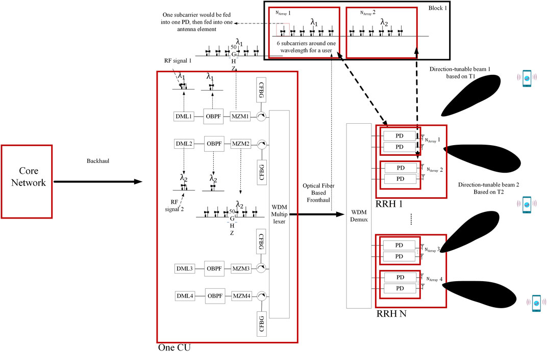
FIGURE 2. Proposed A-RoF system model. (DML: Directly Modulated Laser, OBPF: Optical Bandpass Filter, MZM: Mach-zenhder Modulator, CFBG: Chirped Fiber Bragg Grating, WDM: Wavelength Division Multiplexing, RF: Radio Frequency, CU: Central Unit, RRH: Remote Radio Head, PD: Photo-detector).
Before any data communication between the user equipment and RRHs, user association is performed. One challenge in C-RAN networks is the user association, which significantly enhances the load balancing, the spectrum efficiency as well as the power efficiency of the network (Ejaz et al., 2020). Different resource allocation mechanisms have been proposed for efficient resource management in C-RAN and have been discussed in several surveys including (Olwal et al., 2016; Ejaz et al., 2020; Rodoshi et al., 2020). After user association, the CU has all the information of the users’ association with the RRHs. In this case, each user equipment can be associated with one or more RRHs. Then, the CU decides on the transmission scheme for each user, which will depend on the user association with RRH, the channel quality information for each link as well as the quality of service requirements for each user. More explicitly, one of the characteristics of 5G and beyond mobile networks is their flexibility and ability to support broadband as well as ultra-reliable low latency communications (URLLC). Explicitly, broadband traffic, known as enhanced Mobile Broadband (eMBB) in 5G, can support gigabit per second data rates, while URLLC data requires extremely low delays with very high reliability (99.999%) (3GPP, 2016). Hence, the type of transmitted data, eMBB or URLLC, will also influence the decision of the CU for the transmission scheme for each user.
One option for the transmission from the RRH to the user equipment is to employ beamforming from one RRH to each user equipment. In this case, if the user equipment is associated with more than one RRH, then the CU decides to transmit the downlink signal from the RRH with the best channel quality. Hence, in the following we propose a novel optical aided beamforming for the C-RAN.
Let us first consider the rationale of generating the beams in the RRH1 in Figure 2 in order to clarify our centralized design. As depicted in the CU of Figure 2, the DML is used for the E/O conversion, where DML1 operating at λ1 is modulated by RF signal 1. Then, the modulated optical signal is fed into the MZM1 for generating a WDM signal with frequency spacing of 50 GHz, where each wavelength carries the RF signal 1 as a result of the MZM’s non-linearity. Consequently, the Chirped Fiber Bragg Grating (CFBG) imposes a linear time delay to the different wavelengths of the WDM signal, which can introduce a constant time-delay among the transmit antenna elements in the RRH. More explicitly, the CFBG can introduce the linear time delay by changing its reflective index as a result of imposing varied strains or temperatures (Yunqi Liu et al., 2002). The linear time delay would then be mapped to the time-delay of each RF signal transmitted by each antenna element.
Similarly, the RF signal 2 would be modulated by the DML2 operating at λ2 and time-delayed relying on the CFBG after the MZM2. The two outputs from the above two CFBGs are combined by a WDM multiplexer and coupled into an optical fiber and transmitted to a WDM demultiplexer (WDM Demux). The WDM Demux separates the wavelength carrying RF signal 1 and 2 into the RRH 1, where each output, which has been time-delayed in the CU, is recovered to the RF signal by the photo-detector (PD) and transmitted to the different antenna elements. Specifically, if the wavelengths carrying the RF signal 1 has six wavelength as shown in the block 1 of Figure 2, each wavelength is filtered out using the WDM Demux of Figure 2 and passed to the PDs, capable of recovering the RF signal 1 but with different time-delays. Then, as shown in Figure 2, these time-delayed RF signals 1 are input into the antenna array 1 (Narray 1) having six elements to form the directional beam.
The beam direction can be tuned by the CFBG in the CU by changing its refractive index by applying varying strains or temperatures. Thus, in the RRH 1, two beams with independently tunable beam direction can be supported. On a similar note, in the RRH2, we can also generate two beams by expanding the design of the CU in Figure 2 to two more DML chains. Therefore, this architecture can be potentially exploited for the multi-user MIMO wireless system due to its centralized beam-steering control and the flexible RF spectrum allocation. In our proposed design of Fig. 2, the chirped FBG is capable of imposing a linear relation between the imported wavelengths and their time delay. Here, we aim to characterise the proposed design mathematically. Considering a single chain of the CU in Figure 2, the RF signal is directly modulated by DMLs and the input optical field of the optical bandpass filter (OBPF) is formulated as (Thomas et al., 2015; Li et al., 2018a):
where PLaser is the LD’s output power and
Then, after the optical bandpass filter, which is capable of filtering single side-band of the generated optical signal of E1, we arrive at:
As shown in (Eq. 2), the OBPF is capable of removing one of the side bands of the ODSB signal E1 (t) generated by the MZM. After the OBPF, the signal E2 (t) becomes an optical single side band (OSSB) signal. E1 (t) contains the spectral component of
The MZM output field expressed in Eq. 3 can be combined with Eq. 2 to arrive at (Thomas et al., 2016):
Hence, we have:
where ωΔf, Vdr and Vpi are the angular frequency of Δf, the amplitude of the drive frequency of the MZM and its switching voltage.
Specifically, as illustrated in Figure 2, the spectral components can also be represented by the items A + B + C of Eq. 3, where A contains the spectral components of
MZM output field is derived in (Eq. 3), which results from feeding E2 (t) and the RF signal having the voltage of Vdr to the MZM of Figure 2. According to (Kalman et al., 1994; Ma et al., 2007; Thomas et al., 2015; Thomas et al., 2016; Zhang et al., 2017; Zhai et al., 2021), when the MZM operates at the push-pull mode and applies the quadrature point biasing, the MZM output can be derived and expressed as detailed in (Thomas et al., 2016). Due to the nonlinear transfer function of the MZM, we obtain multiple harmonics by varying the amplitude of the drive voltage applied to the MZM of Figure 2, which is denoted by the Bessel function of (Eq. 3).
Then, the MZM output forms a WDM signal carrying the same signal on each wavelength as depicted in Figure 2. Each wavelength is photo-detected and recovered to the RF signal, where for the simplicity, we derive the RF signal fed into three neighboring elements of Narray1 of Figure 2 as follows:
where t01, t02, t03, t04, t05, and t06 are the time-delays imposed on the wavelengths of
Hence, due to the linear relationship between the time-delay and the optical spectrum, we have Δt = t06 − t05 = t04 − t03 = t02 − t01. Then, by comparing the time-delay of the photo-detected signal S0, S1 and S2, we are capable of obtaining the time-delay difference between S0 and S1 as
In the above description and derivations, we include the 3-antenna element array as a design example, where this design can be extended to any number of elements in the antenna array. We have shown in the above that by imposing the linear time delay on the WDM signal of EMZM (t) we can obtain a constant time delay difference between the neighboring elements. It can be readily verified using similar derivations as presented in (Eqs 3–6) that any arbitrary number of antenna elements would have the same rule of the time-delay difference of
On the other hand, given that many users can be associated with multiple RRHs with a reasonable channel quality, we can consider improving the communication’s performance using diversity techniques combined with the beamforming, for URLLC data for example. Another alternative can be to employ a multiplexing transmission scheme combined with beamforming, in order to attain a higher throughput, which is beneficial for the eMBB scenario.
More specifically, in (Hemadeh et al., 2018) we presented a flexible multi-functional MIMO technique and compared in details the performance of the different configurations, where we have shown that the diversity aided MIMO has the best performance at the expense of reduced throughput as opposed to the multiplexing techniques, which have a higher throughput and reduced bit error rate (BER) performance compared to the diversity techniques. Hence, in this paper we select the following options as the potential transmission schemes from the RRHs to the different users: 1) beamforming using one RRH, 2) beamforming combined with space-time block code (STBC) diversity technique using multiple RRHs to transmit to the specific user, and 3) beamforming combined with spatial modulation (SM) using multiple RRHs to transmit to the specific user3. The CU decides on the transmission scheme for each user, since the CU has all the information needed for making the decision. In the context of the proposed reconfigurable design, a single RRH can connect with a user as shown in Figure 3A, while multiple RRHs can connect to the user as shown in Figure 3B. Furthermore, given the challenges imposed on the A-ROF fronthaul in the proposed C-RAN system, such as the bandwidth, latency and jitter as well as the need for low cost transport network (Checko et al., 2015), in the following we consider the maximum user load that can be supported by the fronthaul link.
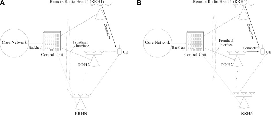
FIGURE 3. (A) RRH1 connected to the user equipment to communicate via beamforming. (B) Two RRHs connected to the user equipment using beamforming combined with STBC or SM.
When the CU makes the decision to transmit to a specific user from one RRH using beamforming, then the optical aided beamforming described above will be employed. Specifically, the proposed architecture in Figure 2 exploits the optical aided beamforming employing CFBG to facilitate a flexible analogue beamforming scheme. More specifically, the optical module of Figure 2 can be employed in the corresponding block of Figure 3, while using algorithm 1 for wireless transmission. Note that, in this paper, we are proposing the beamforming solution, while the user association has been widely investigated (Olwal et al., 2016; Ejaz et al., 2020; Rodoshi et al., 2020).
On the other hand, when a user is associated with multiple RRHs and the fronthaul has the capacity to allow transmission for this user from multiple RRHs, then the CU will decide to transmit using STBC or SM combined with the proposed optical-aided beamforming. First, when the diversity scheme is considered, the CU will choose the RRHs having the highest channel quality metric, to transmit to the specific user. Afterwards, the CU will encode the data to transmit from the multiple RRHs and then transmit it to the RRHs using the above proposed optical aided beamforming. This will result in a diversity gain in addition to the beamforming gain, which results in significant performance improvement compared to the case of using only beamforming from one RRH, while attaining the same throughput.
When the CU decides on the SM as the transmission scheme from the RRHs to the user equipment, then a multiplexing gain can be achieved. In this case, the CU will split the data bit stream to two parts, one for the conventional amplitude and phase modulation (APM) such as PSK/QAM and the other bit stream is used to decide which RRH transmits the signal. Then, the CU transmits the signal to the selected RRH, where the above-proposed optical aided beamforming is performed. Furthermore, in addition to the increased throughput per user attained using this mode, the RRH, which is not transmitting to a specific user can transmit signals to other users, which results in an increased area spectral efficiency or sum rate in addition to the efficient utilisation of the A-ROF fronthaul resources.
Finally, the CU can adaptively decide on the transmission scheme for each user according to Algorithm 1, where the CU categorises users as URLLC and eMBB and then decides on the transmission scheme for each user considering the available resources as well as the channel quality information for each RRH-user link.
As mentioned above, we aim to design an optical aided beamforming system to support the adaptive MU-MIMO system. In our design architecture, we are capable of reducing the beam-squinting resulting from the conventional electronic phase-shifting aided beamforming. In this section, we will evaluate the beamforming performance of the proposed A-ROF aided C-RAN design, followed by a comparison of the beam-squinting phenomenon between our design and the conventional design. As mentioned in Section 3, the optical beamforming system is capable of providing the required beam-steering. In this section, from the perspective of optical communication, we simulate the flexibility and range of the optical aided beamforming techniques. Table 1 lists the simulation parameters, where we invoke an antenna array having 6 elements. We consider a radio frequency (RF) signal at 3 GHz, which is transmitted by the A-RoF system and carried by a WDM signal of wavelengths as shown in Table 1. In our simulation, the RF signal is generated off-line by Matlab and then we measure the time delay using the OptiGrating, a software for designing the fiber Bragg grating.
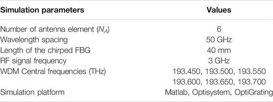
TABLE 1. Simulation parameters.
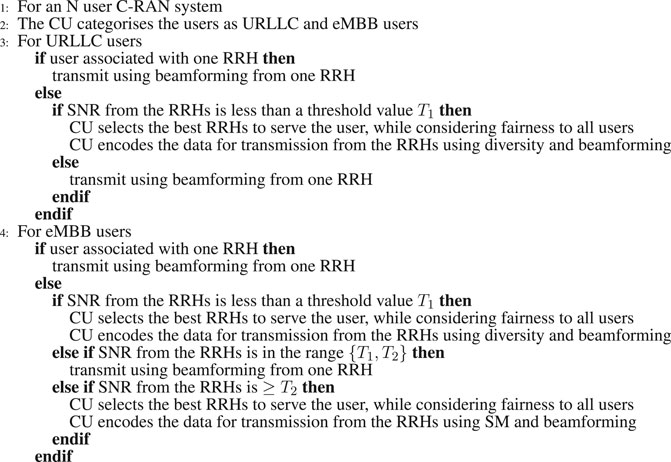
ALGORITHM 1. Reconfigurable MIMO transmission in C-RAN
As discussed in Section 3, the RF signal is first used to directly modulate a laser source. The directly modulated signal is bandpass filtered to obtain a single side-band modulated carrier and then the output of the bandpass filter is passed through a MZM that is driven by a sinusoidal signal having a frequency of 50 GHz. This results in the generation of multiple side-bands at the output of the MZM due to its non-linearity. These side-bands are then passed through the CFBG which induces a different delay over each side-band depending on the wavelength. As mentioned earlier, the CFBG was implemented using the commercial tool OptiGrating, which gives the values of the delays induced over each side-band. We use these delays to calculate the angle of the beam obtained at the output of the antenna array. The delays can be tuned by varying the period of the CFBG.
By tuning the CFBG of Figure 2, we can obtain a beamforming coverage of almost 180° as depicted in Figure 4. More specifically, we apply six antenna elements to validate our flexible beam-steering scheme of Figure 2. Each beam emitted from around 95° to 265° to the orientation of the antenna array in Figure 4 is generated by tuning the total chirp of the CFBG implemented in the CU of Figure 2 from 0.7 to 4. Thus, any beam direction shown in Figure 4 can be used for the wireless beam-steering and the multi-user MIMO as discussed in Section 3, which results in multi-user beamforming as shown in Figure 5.
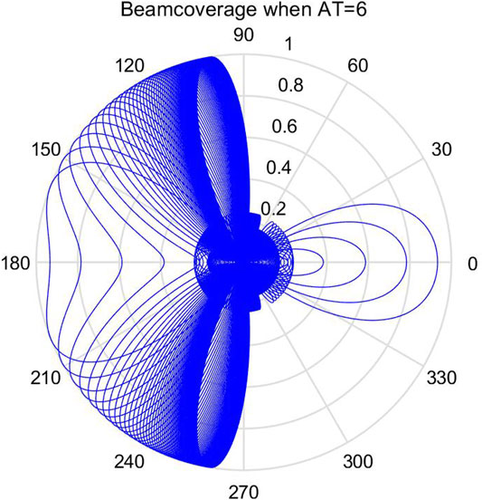
FIGURE 4. Beam coverage.
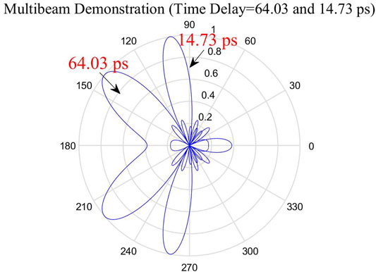
FIGURE 5. Multi-user beams.
Furthermore, as shown in Figure 2, the beamforming angle emitted from each antenna array can be independently tuned by imposing temperature or strain on the corresponding CFBG (Yunqi Liu et al., 2002). Thus, multi-beam can be flexibly generated since each beam is related to different CFBG in the CU of Figure 2, where the time-delay is independently tuned. In Figure 6 we show the relation between the wavelength and the time delay imposed by the CFBG, where the time delay difference among the neighbouring wavelengths of the WDM signal of Fig. 2 can be tuned by changing the gradients of the curves in Figure 6, as a result of tuning the total chirps of the CFBG. Note that in Figure 6, we show two different curves for two different values of the total chirp as example values to verify the tunability of the linear relations with the tuning of the total chirps of the CFBG.
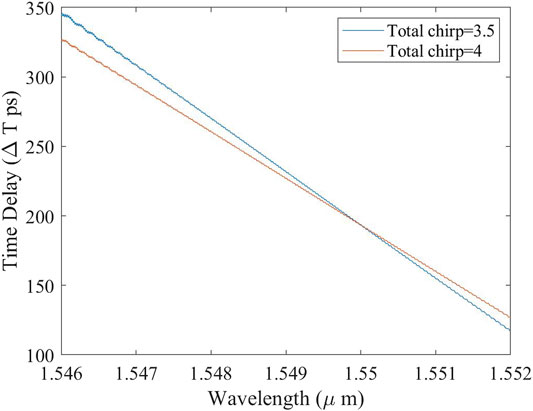
FIGURE 6. Time delay versus wavelength.
It may be observed from Table 1 that the wavelengths we have chosen for transmission of the RF signals have a range of 1,548.78nm–1,550.78 nm. For these wavelengths, the time delay has values between 180 and 280 ps, as may be observed from Figure 6, which shows the linear relationship between the wavelengths and the time-delay of the WDM signal of Figure 2 provided by the CFBG. Here, the linear optical time-delay can be translated to the constant antenna time-delay differences of
Additionally, multiple beams to support multiple users can be realised using the proposed system. Figure 5 shows an example two beams generated with different angles, where we tune the time delay difference among the neighboring wavelength to 64.03 and 14.73 ps, which correspond to the total chirp of 0.85 and 3.65, respectively. Therefore, we show in Figure 5 that our system is capable of supporting multi-user beamforming by simply tuning the total chirp to map the beam to the desired direction. The beam direction range can be further enhanced by reconfiguring the CFBG’s length or grating period.
Finally, the beam squinting impairment resulting from the phase-shifting based beamforming can be mitigated by our true-time delay scheme as shown in Figure 7, where the true-time delay scheme can effectively remove the beam-squinting phenomenon of the phase-shifting scheme. Hence, the A-RoF based true-time delay system is capable of supporting the multi-user transmission dispensing with the phase shifters, while supporting flexible beam steering control and removing the beam-squinting problems. Compared to the conventional system of Figure 1, our proposed system utilizes the passive CFBGs for an all-optical beamforming solution and a true-time delay phased array system. This system can facilitate the channel estimation and precoding scheme (Wang et al., 2019), while improving the bandwidth and increasing the number of antennas (Cai et al., 2016)4.
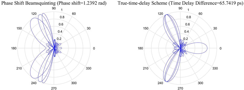
FIGURE 7. Illustration of the beam squinting phenomenon.
In this paper we proposed an A-RoF aided architecture for supporting the requirements of the current and future mobile networks, where we designed a photonics aided beamforming technique in order to eliminate the bulky electronic phase-shifters and the beam-squinting effect while providing a low-cost RAN solution. We showed that the proposed system is capable of providing a beamforming range of 180°, while also supporting multiple users. Then, we presented a reconfigurable multi-user MIMO system utilising the proposed beamforming technique, in order to allow improved performance or increased throughput for the different users depending on the channel quality as well as the user requirements.
The raw data supporting the conclusion of this article will be made available by the authors, without undue reservation.
All authors listed have made a substantial, direct, and intellectual contribution to the work and approved it for publication.
The authors declare that the research was conducted in the absence of any commercial or financial relationships that could be construed as a potential conflict of interest.
All claims expressed in this article are solely those of the authors and do not necessarily represent those of their affiliated organizations, or those of the publisher, the editors and the reviewers. Any product that may be evaluated in this article, or claim that may be made by its manufacturer, is not guaranteed or endorsed by the publisher.
MFUB would like to gratefully acknowledge the Higher Education Commission (HEC), Government of Pakistan’s financial support through its Post-Doctoral Fellowship Program (PDFP) Grant.
1This is a design example and the proposed design can be extended to any arbitrary number of CUs and RRHs.
2This also applies to Narray2, Narray3 and Narray4, since these antenna arrays receive the RF signals carried by the same form of optical spectra except the center frequencies as shown in Figure 2, which can also be derived by (Eqs 3–6).
3Note that this is an example configuration and any other MIMO techniques can be used.
4This analysis is outside the scope of this paper, where the corresponding researches can be found in (Cai et al., 2016; Wang et al., 2019). Furthermore, in (Li et al., 2018a), it was verified that the implementation of the CFBG in Figure 2 will not affect the system performance of those without implementing the A-RoF aided C-RAN, while achieving a 10 Gbps system.
Blogh, J., and Hanzo, L. (2002). Third-Generation Systems and Intelligent Wireless Networking: Smart Antennas and Adaptive Modulation. Wiley.
Cai, M., Gao, K., Nie, D., Hochwald, B., Laneman, J. N., Huang, H., et al. (2016). Effect of Wideband Beam Squint on Codebook Design in Phased-Array Wireless Systems. In 2016 IEEE Global Communications Conference (GLOBECOM). 1–6. doi:10.1109/GLOCOM.2016.7841766
Cao, Z., Lu, R., Wang, Q., Tessema, N., Jiao, Y., van den Boom, H. P. A., et al. (2014). Cyclic Additional Optical True Time Delay for Microwave Beam Steering with Spectral Filtering. Opt. Lett. 39, 3402–3405. doi:10.1364/OL.39.003402
Cao, Z., Ma, Q., Smolders, A. B., Jiao, Y., Wale, M. J., Oh, C. W., et al. (2016). Advanced Integration Techniques on Broadband Millimeter-Wave Beam Steering for 5G Wireless Networks and beyond. IEEE J. Quan. Electron. 52, 1–20. doi:10.1109/jqe.2015.2509256
Checko, A., Christiansen, H. L., Yan, Y., Scolari, L., Kardaras, G., Berger, M. S., et al. (2015). Cloud RAN for Mobile Networks-A Technology Overview. IEEE Commun. Surv. Tutorials 17, 405–426. doi:10.1109/COMST.2014.2355255
Dogan-Tusha, S., Tusha, A., Basar, E., and Arslan, H. (2020). Multidimensional index Modulation for 5G and beyond Wireless Networks.
Ejaz, W., Sharma, S. K., Saadat, S., Naeem, M., Anpalagan, A., and Chughtai, N. A. (2020). A Comprehensive Survey on Resource Allocation for CRAN in 5G and beyond Networks. J. Netw. Comp. Appl. 160, 102638. doi:10.1016/j.jnca.2020.102638
Hanzo, L., El-Hajjar, M., and Alamri, O. (2011). Near-capacity Wireless Transceivers and Cooperative Communications in the MIMO Era: Evolution of Standards, Waveform Design, and Future Perspectives. Proc. IEEE 99, 1343–1385. doi:10.1109/JPROC.2011.2148150
Hanzo, L., El-Hajjar, M., and Alamri, O. (2011). Near-Capacity Wireless Transceivers and Cooperative Communications in the MIMO Era: Evolution of Standards, Waveform Design, and Future Perspectives. Proc. IEEE 99, 1343–1385. doi:10.1109/JPROC.2011.2148150
Hanzo, L., Haas, H., Imre, S., O'Brien, D., Rupp, M., and Gyongyosi, L. (2012). Wireless Myths, Realities, and Futures: from 3G/4G to Optical and Quantum Wireless. Proc. IEEE 100, 1853–1888. doi:10.1109/jproc.2012.2189788
Hemadeh, I. A., El-Hajjar, M., and Hanzo, L. (2018). Hierarchical Multi-Functional Layered Spatial Modulation. IEEE Access 6, 9492–9533. doi:10.1109/ACCESS.2018.2802863
Huang, H., Wang, X., Zhang, C., Fu, S., Liu, D., and Qiu, K. (2021). Optically Centralized Beamforming for Reconfigurable Intelligent Surface-Aided Mmwave Cloud Ran. In 2021 IEEE Wireless Communications and Networking Conference (WCNC). 1–6. doi:10.1109/WCNC49053.2021.9417589
Huang, H., Zhang, C., Chen, C., Wu, T., Huang, H., and Qiu, K. (2018). Optical True Time Delay Pools Based Centralized Beamforming Control for Wireless Base Stations Phased-Array Antennas. J. Lightwave Technol. 36, 3693–3699. doi:10.1109/JLT.2018.2849001
Hunter, D. B., Parker, M. E., and Dexter, J. L. (2006). Demonstration of a Continuously Variable True-Time Delay Beamformer Using a Multichannel Chirped Fiber Grating. IEEE Trans. Microwave Theor. Techn. 54, 861–867. doi:10.1109/tmtt.2005.863056
Ishikawa, N., Sugiura, S., and Hanzo, L. (2018). 50 Years of Permutation, Spatial and index Modulation: From Classic RF to Visible Light Communications and Data Storage. IEEE Commun. Surv. Tutorials 20, 1905–1938. doi:10.1109/COMST.2018.2815642
Jianping Yao, J., Jianliang Yang, J., and Yunqi Liu, Y. (2002). Continuous True-Time-Delay Beamforming Employing a Multiwavelength Tunable Fiber Laser Source. IEEE Photon. Technol. Lett. 14, 687–689. doi:10.1109/68.998726
Kalman, R. F., Fan, J. C., and Kazovsky, L. G. (1994). Dynamic Range of Coherent Analog Fiber-Optic Links. J. Lightwave Technol. 12, 1263–1277. doi:10.1109/50.30182010.1109/50.301820
Li, Y., El-Hajjar, M., and Hanzo, L. (2018). Joint Space-Time Block-Coding and Beamforming for the Multiuser Radio over Plastic Fiber Downlink. IEEE Trans. Veh. Technol. 67, 2781–2786. doi:10.1109/TVT.2017.2723876
Li, Y., Ghafoor, S., Satyanarayana, K., El-Hajjar, M., and Hanzo, L. (2019). Analogue Wireless Beamforming Exploiting the Fiber-Nonlinearity of Radio over Fiber-Based C-RANs. IEEE Trans. Veh. Technol. 68, 2802–2813. doi:10.1109/TVT.2019.2893589
Li, Y., Hemadeh, I. A., El-Hajjar, M., and Hanzo, L. (2018a). Radio over Fiber Downlink Design for Spatial Modulation and Multi-Set Space-Time Shift-Keying. IEEE Access 6, 21812–21827. doi:10.1109/ACCESS.2018.2821642
Li, Y., Wang, F., El-Hajjar, M., and Hanzo, L. (2020). Analogue Radio over Fiber Aided Optical-Domain MIMO Signal Processing for High-Performance Low-Cost Radio Access Networks. IEEE Commun. Mag.
Li, Y., Yang, Q., Hemadeh, I. A., El-Hajjar, M., Chan, C.-K., and Hanzo, L. (2018b). Experimental Characterization of the Radio over Fiber Aided Twin-Antenna Spatial Modulation Downlink. Opt. Express 26, 12432–12440. doi:10.1364/OE.26.012432
Ma, J., Yu, J., Yu, C., Xin, X., Zeng, J., and Chen, L. (2007). Fiber Dispersion Influence on Transmission of the Optical Millimeter-Waves Generated Using Ln-Mzm Intensity Modulation. J. Lightwave Technol. 25, 3244–3256. doi:10.1109/JLT.2007.907794
Molony, A., Zhang, L., Willlams, J., Bennion, I., Edge, C., and Fells, J. (1996). Fiber Bragg Grating Networks for Time-Delay Control of Phased-Array Antennas. In Lasers and Electro-Optics, 1996. CLEO’96., Summaries of papers presented at the Conference on. IEEE, 244–245.
Olwal, T. O., Djouani, K., and Kurien, A. M. (2016). A Survey of Resource Management toward 5G Radio Access Networks. IEEE Commun. Surv. Tutorials 18, 1656–1686. doi:10.1109/COMST.2016.2550765
Ortega, B., Mora, J., and Chulia, R. (2016). Optical Beamformer for 2-D Phased Array Antenna with Subarray Partitioning Capability. IEEE Photon. J. 8, 1–9. doi:10.1109/JPHOT.2016.2550323
Poon, A. S. Y., and Taghivand, M. (2012). Supporting and Enabling Circuits for Antenna Arrays in Wireless Communications. Proc. IEEE 100, 2207–2218. doi:10.1109/JPROC.2012.2186949
Rodoshi, R. T., Kim, T., and Choi, W. (2020). Resource Management in Cloud Radio Access Network: Conventional and New Approaches. Sensors (Basel) 20. doi:10.3390/s20092708
Rotman, R., Tur, M., and Yaron, L. (2016). True Time Delay in Phased Arrays. Proc. IEEE 104, 504–518. doi:10.1109/JPROC.2016.2515122
Satyanarayana, K., El-Hajjar, M., Mourad, A. A. M., and Hanzo, L. (2019). Deep Learning Aided Fingerprint-Based Beam Alignment for Mmwave Vehicular Communication. IEEE Trans. Veh. Technol. 68, 10858–10871. doi:10.1109/TVT.2019.2939400
Srivastava, N. K., Parihar, R., and Raghuwanshi, S. K. (2020). Efficient Photonic Beamforming System Incorporating a Unique Featured Tunable Chirped Fiber Bragg Grating for Application Extended to the Ku-Band. IEEE Trans. Microwave Theor. Techn. 68, 1851–1857. doi:10.1109/TMTT.2019.2961889
Thomas, V. A., El-Hajjar, M., and Hanzo, L. (2016). Millimeter-wave Radio over Fiber Optical Upconversion Techniques Relying on Link Nonlinearity. IEEE Commun. Surv. Tutorials 18, 29–53. doi:10.1109/COMST.2015.2409154
Thomas, V. A., El-Hajjar, M., and Hanzo, L. (2015). Performance Improvement and Cost Reduction Techniques for Radio over Fiber Communications. IEEE Commun. Surv. Tutorials 17, 627–670. doi:10.1109/COMST.2015.2394911
Tsakyridis, A., Ruggeri, E., Kalfas, G., Oldenbeuving, R. M., van Dijk, P. W. L., Roeloffzen, C. G. H., et al. (2021). Reconfigurable Fiber Wireless Ifof Fronthaul with 60 Ghz Phased Array Antenna and Silicon Photonic Roadm for 5g Mmwave C-Rans. IEEE J. Select. Areas Commun. 1, 1. doi:10.1109/JSAC.2021.3064649
UN2 (2015). Resolution Adopted by the General Assembly on Transforming Our World: the 2030 Agenda for Sustainable Development (a/res/70/1).
Wang, B., Jian, M., Gao, F., Li, G. Y., and Lin, H. (2019). Beam Squint and Channel Estimation for Wideband Mmwave Massive MIMO-OFDM Systems. IEEE Trans. Signal. Process. 67, 5893–5908. doi:10.1109/TSP.2019.2949502
Xiaojing Huang, X., and Guo, Y. J. (2011). Frequency-domain AoA Estimation and Beamforming with Wideband Hybrid Arrays. IEEE Trans. Wireless Commun. 10, 2543–2553. doi:10.1109/TWC.2011.062211.100439
Yang, D.-H., and Lin, W.-P. (2015). Phased-array Beam Steering Using Optical True Time Delay Technique. Opt. Commun. 350, 90–96. doi:10.1016/j.optcom.2015.03.066
Ye, X., Zhang, F., and Pan, S. (2015). Optical True Time Delay Unit for Multi-Beamforming. Opt. Express 23, 10002–10008. doi:10.1364/OE.23.010002
Yunqi Liu, Yunqi., Jianliang Yang, Jianliang., and Jianping Yao, Jianping. (2002). Continuous True-Time-Delay Beamforming for Phased Array Antenna Using a Tunable Chirped Fiber Grating Delay Line. IEEE Photon. Technol. Lett. 14, 1172–1174. doi:10.1109/lpt.2002.1022008
Zhai, W., Wen, A., and Shan, D. (2021). Multidimensional Optimization of a Radio-Over-Fiber Link. IEEE Trans. Microwave Theor. Techn. 69, 210–221. doi:10.1109/TMTT.2020.3021095
Zhang, H., Cai, L., Xie, S., Zhang, K., Wu, X., and Dong, Z. (2017). A Novel Radio-Over-Fiber System Based on Carrier Suppressed Frequency Eightfold Millimeter Wave Generation. IEEE Photon. J. 9, 1–6. doi:10.1109/JPHOT.2017.2731620
Keywords: optical fiber, radio access network, beyond 5G, analogue radio over fiber, beamfoming
Citation: Li Y, Ghafoor S, Butt MFU and El-Hajjar M (2021) Analog Radio Over Fiber Aided C-RAN: Optical Aided Beamforming for Multi-User Adaptive MIMO Design. Front. Comms. Net 2:725976. doi: 10.3389/frcmn.2021.725976
Received: 16 June 2021; Accepted: 09 August 2021;
Published: 31 August 2021.
Edited by:
Osama Amin, King Abdullah University of Science and Technology, Saudi ArabiaReviewed by:
Chunguo Li, Southeast University, ChinaCopyright © 2021 Li, Ghafoor, Butt and El-Hajjar. This is an open-access article distributed under the terms of the Creative Commons Attribution License (CC BY). The use, distribution or reproduction in other forums is permitted, provided the original author(s) and the copyright owner(s) are credited and that the original publication in this journal is cited, in accordance with accepted academic practice. No use, distribution or reproduction is permitted which does not comply with these terms.
*Correspondence: Yichuan Li, bGl5aWNodWFuQGhpdC5lZHUuY24=
Disclaimer: All claims expressed in this article are solely those of the authors and do not necessarily represent those of their affiliated organizations, or those of the publisher, the editors and the reviewers. Any product that may be evaluated in this article or claim that may be made by its manufacturer is not guaranteed or endorsed by the publisher.
Research integrity at Frontiers
Learn more about the work of our research integrity team to safeguard the quality of each article we publish.