
95% of researchers rate our articles as excellent or good
Learn more about the work of our research integrity team to safeguard the quality of each article we publish.
Find out more
ORIGINAL RESEARCH article
Front. Clim. , 04 August 2022
Sec. Carbon Dioxide Removal
Volume 4 - 2022 | https://doi.org/10.3389/fclim.2022.946735
This article is part of the Research Topic CO2 Mineralization: A Carbon Storage Technology for a Sustainable Future View all 5 articles
 Adrien Dufourny1
 Carine Julcour1Jérôme Esvan2Laurent Cassayre1
 Priscillia Laniesse3
 Florent Bourgeois1*
The main obstacle to the aqueous carbonation of non-serpentinised magnesium silicates is the formation of surface passivation layers, which severely limits the reaction rate and thus the overall efficiency of the process. A technological solution to overcome this problem is to perform the carbonation process inside a stirred bead mill, which aims to continuously remove the surface by-product layers by attrition. In this work, the aqueous carbonation of ferronickel slag, a mineralogically complex mining waste composed of a Mg/Si rich amorphous phase and a crystalline ferrous forsterite, was studied at 150°C and under 10 bar of CO2 with different operating configurations: carbonation alone (C mode), attrition followed by carbonation (A-C mode) and concomitant attrition and carbonation (AC mode). By careful observation of the mineralogy and the surface of the secondary phases formed using complementary analytical techniques, the article allows a better understanding of the passivation phenomenon inherent to the carbonation of magnesium silicates, and confirms the effectiveness of continuous surface mechanical depassivation for reaching high carbonation rates with this type of material. Comparative analysis of the products obtained with the three operating modes shows that a true synergy takes place between attrition and carbonation due to the combined effect of continuous exfoliation and mechanical activation of particle surface, which goes far beyond the simple increase in surface area due to particle size reduction. While mechanical depassivation is here substantiated by several evidence, the additional mechanochemical activation effect cannot be delineated from experiment; however its beneficial contribution to carbonation is inferred from its observation in A-C mode. The work finds that the synergy between attrition and carbonation also yields very characteristic products. They consist in micrometric agglomerates formed by bound spherical particles a few tens of nanometers in size. These particles themselves contain an entanglement of nanometric grains of carbonates and amorphous silica dispersed inside a magnesium-depleted alumino-siliceous matrix. These results confirm that concomitant attrition and carbonation offers one of the most promising pathways for developing direct aqueous carbonation processes with non-thermally activatable magnesium silicates.
Over the past 3 decades, mineral carbonation has progressively developed, structured and imposed itself as a realistic way to mitigate CO2 emissions (Seifritz, 1990; Lackner et al., 1995; Huijgen and Comans, 2003; Sanna et al., 2014; Yadav and Mehra, 2021). It consists in entrapping CO2 in a highly stable solid form as carbonates formed by reaction between CO2 and a magnesium or calcium bearing feedstock in an aqueous medium. Mineral carbonation products, primarily silica and carbonates, are stable under weakly acidic natural precipitation conditions and CO2 can be stored for more than 100,000 years (Lackner, 2003; Wang et al., 2018). A distinction is made between in-situ mineral carbonation, which consists in trapping CO2 in geological reservoirs (natural gas reservoirs, oil reservoirs, brine reservoirs, etc.) where carbonation reactions occur with the host rock, and ex-situ mineral carbonation, where carbonation reactions are carried out in a dedicated optimizable process or plant.
Natural feedstocks used for mineral carbonation are Mg, Fe or Ca-rich silicates, which are plentiful in the Earth's crust. Key minerals are serpentine [Mg3Si2O5(OH)4] (antigorite, lizardite, chrysotile) and olivine [Mg2SiO4] (forsterite) which react with CO2 to form anhydrous or hydrated magnesium carbonates like magnesite (MgCO3), hydromagnesite (Mg5(CO3)4(OH)2.4H2O) and nesquehonite (MgCO3.3H2O) (Guermech et al., 2022), or wollastonite (CaSiO3) which forms calcite (CaCO3). The steps that limit the reaction can be the dissolution of CO2 in the aqueous solution, the dissolution of silicates, the lack of liberation of leachable phases, and the passivating precipitation of silica-rich layers and carbonates on the surface of the particles (Sanna et al., 2014).
Among natural magnesium feedstocks, it is clear that there is a significant difference between serpentinized and non-serpentinized materials from the point of view of the passivation phenomenon. The former allow the carbonation of a significant amount of labile Mg by controlled thermal activation (dehydroxylation), which transforms the material into a reactive amorphous phase (McKelvy et al., 2004; Dlugogorski and Balucan, 2014; Pasquier et al., 2014; Rim et al., 2020). It is worth noting that the energy expended for this high temperature activation pretreatment is partially and inefficiently recovered through the low temperature exothermicity of the carbonation reaction. Thus, a significant number of studies have focused on the carbonation of heat-treated serpentine (Werner et al., 2013, 2014; Dlugogorski and Balucan, 2014; Pasquier et al., 2014; Hariharan and Mazzotti, 2017; Du Breuil et al., 2019; Rim et al., 2020). The latter, exemplified by olivine, undergo a shrinking core dissolution: a silica-rich passivation layer forms during the reaction, which opposes the carbonation process. The nature and in particular the permeability of this surface layer depends on material factors, such as the structure and chemical composition of the feedstock and the implementation and operating conditions of the carbonation process (Schott and Berner, 1983; Béarat et al., 2006; Julcour et al., 2015; Wang et al., 2019). The characteristics of these surface layers is discussed in more detail afterwards. For natural calcium feedstocks, wollastonite has emerged as the most prized mineral (Huijgen et al., 2006; Daval et al., 2009; Ding et al., 2014; Min et al., 2017; Di Lorenzo et al., 2018). In general, the overall carbonation kinetics are significantly higher with calcic feedstocks, which is partly explained by the slower precipitation kinetics of MgCO3 compared to CaCO3, as reported by Saldi et al. (2009).
In recent years, scientific and commercial developments have intensified around the carbonation of anthropogenic wastes in a quest for greater circularity of the economy and wealth creation. The review by Yadav and Mehra (2021) reports a detailed mapping of carbonatable industrial wastes, including steel slag, cement wastes, mining wastes (asbestos, nickel tailings, red mud), household waste incineration ashes and paper industry wastes. Compared to natural minerals, industrial wastes are available in significantly smaller quantities. They represent a feedstock category of their own, as they exhibit compositions, in metals particularly, and reactivities that are generally higher than those of natural materials (Huijgen et al., 2005; Gadikota et al., 2015).
Although thermodynamically favored, mineral carbonation reactions are naturally slow. The most favorable pathway in this respect is ex-situ aqueous mineral carbonation (Doucet, 2011), as opposed to in-situ and dry mineral carbonation. Several approaches have been studied, alone or in combination to increase the kinetics and the advancement of aqueous carbonation reactions: particle size reduction, temperature, CO2 partial pressure, pH, thermal activation, chemical additives, catalysts, concomitant grinding and carbonation (O'Connor et al., 2001; Park and Fan, 2004; Chizmeshya et al., 2007; Gerdemann et al., 2007; Rashid et al., 2019, 2021; Rim et al., 2020). Invariably, the associated demands in energy, additives or consumables become sensitive issues as they tend to oppose the net benefit of the carbonation process.
Compared to other techniques, the use of concomitant grinding in mineral carbonation is relatively new and under-researched. A better understanding of the mechanisms that govern the performance of this process is deemed necessary to envisage turning it into a viable mineral carbonation process. Moreover, because of their refractory character to carbonation, only few studies (Julcour et al., 2015; Rashid et al., 2019, 2021; Wang et al., 2019; Rim et al., 2020) have focused specifically on aqueous carbonation of olivine type feedstocks aided by attrition. Consideration of physical abrasion as a means to eliminate passivated surfaces in the context of mineral carbonation dates back to 2004 with the work of Penner et al. (2004). The authors posited that a possible advantage of the highly turbulent environment provided by their flow-loop carbonation reactor was high-energy particle-particle interactions, which they suspected could exfoliate passivated surfaces and thus produce additional dissolution and reaction of Mg. The search for solutions to deliberately apply abrasion during the carbonation process was later reported by Julcour et al. (2015), followed by Rashid et al. (2019, 2021) and Rim et al. (2020). Julcour et al. (2015) exemplified the performance and robustness of concurrent attrition and carbonation for a suite of natural Mg-silicates and put forward the hypothesis of a synergy between the two processes. A following-up work on the kinetic modeling of this concurrent process applied to a ferronickel slag (Julcour et al., 2020) suggested the existence of a limit size below which attrition becomes ineffective at removing the by-product layers, but whose experimental proof needed to be provided. Rashid et al. (2019) concluded on the benefit of concurrent grinding for minerals unresponsive to thermal activation. In Rashid et al. (2021), punctual semi-quantitative EDS measurements of particle surface and core's chemical composition led them to conclude to the continuous removal of silica-rich surface layers on the surface of natural dunite, olivine and lizardite ores. Adding grinding beads to a PCO2-swing aqueous carbonation process, Rim et al. (2020) looked at the effect of continuous abrasion on carbonation of heat-activated serpentine. Applying a stress intensity approach derived from that used to scale and optimize stirred mills for fine grinding, they looked into the effect of surface vs. body fragmentation on carbonation efficiency. Against intuition, they concluded that the latter was more effective at continuously removing Si-rich layers and improving carbonation efficiency. The present paper is another contribution to understanding the effect of concurrent attrition and carbonation, with the demonstration of depassivation at its core, in particular by a combination of chemical surface analyses.
Economic attractiveness of ex-situ mineral carbonation demands that the reaction proceeds quickly and reaches a high conversion rate. The added-value of the carbonation products is also critical, as it is today the main carbonation process development driver. Commercial targets for carbonation products are construction materials (supplementary cementitious materials, hydraulic binders) for Ca and Mg feedstocks and precipitated calcium carbonates (PCC) for calcium feedstocks (Gadikota et al., 2015; Yadav and Mehra, 2021). Besides the energy cost of mineral carbonation, which translates directly into CO2, eq emissions if the energy used is not of renewable origin, a point of consideration is its potential value from the viewpoint of waste management. Indeed, ex-situ mineral carbonation is now widely understood as a way to co-valorize CO2 and industrial wastes in order to produce useful commercial materials. The legitimacy of carbonation in the circular economy then implies the valorisation of part or all of its products. The valorisation of industrial and urban wastes presents a challenge in relation to natural resources, insofar as they contain a many trace elements, metals in particular, which are often undesirable in commercial products. The value of the carbonation products can be the inerting of the metals to which the carbonation reactions can lead. The reduction of toxicity of carbonated wastes can thus allow them to be stored at a significantly lower cost than the original waste. Conversely, production of PCC from waste can potentially produce a significant amount of Ca-depleted solid wastes whose valorization or storage can be an issue. The valorization of carbonation products is therefore a critical factor for the development of mineral carbonation. Thus, the positioning of mineral carbonation as a way of producing useful and recoverable materials has encouraged the emergence of early opportunities, which have logically focused on the carbonation of calcium feedstocks, with more favorable implementation conditions and carbonation yields. This has already led to the development of several successful enterprises, such as Solidia Technologies (Meyer et al., 2018), Carbon 8 (Guning and Hills, 2014), CarbonCure (Monkman and Shao, 2010) and MCi (Brent et al., 2015) to only name a few, each in different sectors of mineral carbonation and not necessarily directly treating silicate minerals.
Figure 1, despite its somewhat simplistic view of the status of current ex-situ mineral carbonation developments, highlights the maturity gap in research and development for magnesium feedstocks. This paper and the research program to which is it attached are mainly directed toward reducing the knowledge gap about mineral carbonation of magnesium feedstocks, particularly non-serpentinized magnesium ores and wastes, with views on developing viable operational processes for such feedstocks.

Figure 1. Overview of ex-situ mineral carbonation developments (++ High maturity/commercial developments, + Significant research and development, - largely unexplored).
As previously mentioned, the performance of mineral carbonation can be strongly impacted by the formation of dissolution layers on the surface of native particles (Béarat et al., 2006; Kwak et al., 2010; Daval et al., 2011; Saldi et al., 2013; Johnson et al., 2014; Julcour et al., 2015; Li et al., 2018; Gadikota et al., 2020). It is also a phenomenon found in the natural alteration of silicates in acidic conditions (Casey et al., 1989; Velbel, 1993; Zakaznova-Herzog et al., 2008; Hellmann et al., 2012; Ruiz-Agudo et al., 2012; Schott et al., 2012; Monasterio-Guillot et al., 2021a,b). The complexity of the formation and nature of these surface layers explains why their characterization has been explored using numerous analytical techniques: X-ray photoelectron spectroscopy (Zakaznova-Herzog et al., 2008), Raman spectroscopy (Ruiz-Agudo et al., 2012), infrared spectroscopy (Schott et al., 2012; Monasterio-Guillot et al., 2021b), atomic force microscopy (Hellmann et al., 2012; Ruiz-Agudo et al., 2012), small angle X-ray scattering (Schott et al., 2012), 29Si NMR spectroscopy (Kwak et al., 2010; Schott et al., 2012; Rim et al., 2020), SEM and TEM observations (Béarat et al., 2006; Kwak et al., 2010; Schott et al., 2012; Saldi et al., 2013; Johnson et al., 2014; Sissmann et al., 2014; Julcour et al., 2015; Li et al., 2018; Rim et al., 2020; Monasterio-Guillot et al., 2021b), TEM/EDX analysis of FIB sections (Casey et al., 1989; Béarat et al., 2006; Daval et al., 2011; Hellmann et al., 2012; Sissmann et al., 2014; Julcour et al., 2015).
These numerous studies have revealed the great variability of dissolution co-product layers, whose composition and morphology depend on:
- operating conditions : temperature (Julcour et al., 2015), presence of CO2 (Kwak et al., 2010) or O2 (Saldi et al., 2013), contact time between the fluid and the solid (Saldi et al., 2013; Monasterio-Guillot et al., 2021b), salinity of the aqueous phase (Johnson et al., 2014; Gadikota et al., 2020),
- feedstock's initial phases: silicates or aluminosilicates (Gadikota et al., 2020), calcium or magnesium silicates (Daval et al., 2011), with significant differences in composition, crystallography and reactivity between these native phases, with a possible epitactic interaction between the deposition layer and the underlying phase (Daval et al., 2011; Hellmann et al., 2012),
- the presence of impurities in reactive phases: iron in particular, which can enhance the passivating character of the siliceous leached layer (Saldi et al., 2013),
- the chemical environment, i.e., the presence of elements (Al, Fe) in the other phases that coexist inside the ore (Sissmann et al., 2014; Li et al., 2018).
The few common characteristics of these layers are their amorphous character and their higher silicon content than the native phases.
Among the surface layers' formation mechanisms, dissolution-precipitation at the fluid-solid interface is the most commonly accepted. It explains, at the same time, the steep variations of elemental concentration between the native mineral phase and the product layers, the precipitation of siliceous phases below their apparent saturation based on the liquid phase composition, and the effect of the liquid-solid contact time on their formation (Zakaznova-Herzog et al., 2008; Daval et al., 2011; Schott et al., 2012). These layers need thus to be considered as evolving materials, possibly subject to densification, cracking or redissolution phenomena during the conversion of the ore (Béarat et al., 2006; Kwak et al., 2010; Daval et al., 2011; Saldi et al., 2013; Brent et al., 2015).
In the context of mineral carbonation, studies were particularly focused on the case of forsterite (Béarat et al., 2006; Kwak et al., 2010; Daval et al., 2011; Saldi et al., 2013; Johnson et al., 2014; Sissmann et al., 2014; Brent et al., 2015; Li et al., 2018). Most authors mention the formation of a single amorphous layer, enriched in silicon and depleted in magnesium. Depending on the operating conditions, it can be a quasi-impermeable layer of silica and iron (III) a few tens of nanometers thick, or a thick (around 1 μm) and diffuse phyllosilicate layer (Julcour et al., 2015). In the absence of iron or under anoxic conditions, the silica layer can however allow the migration of cations (Saldi et al., 2013).
It should be noted that more complex passivation mechanisms have been reported in the case of basalts or garnets (Hellmann et al., 2012; Sissmann et al., 2014). These can yield stratified layers with parallel zones of different structure and composition (Hellmann et al., 2012) or different layers formed on the surface of grains of distinct mineral phases that coexist inside the ore (Sissmann et al., 2014).
While the paper touches upon a variety of issues related to the quest for efficient aqueous carbonation pathways for magnesium bearing feedstocks, the main contribution of this communication is 2-fold. Firstly, through the prism of the carbonation inside a stirred bead mill of a nickel slag, a Mg/Si-rich pyrometallurgical waste that cannot be activated thermally, the work aims to establish the synergistic effect between attrition and carbonation on depassivation of reactive surfaces and direct aqueous carbonation performance. Secondly, through observation of carbonation products formed with and without attrition by means of complementary physico-chemical characterization techniques (TGA, elemental analysis, XRD, SEM & TEM/EDX, XPS, gas porosimetry, particle size distribution) and thermodynamic predictions, the paper aims at an improved understanding of magnesium silicates' surface passivation and depassivation phenomena during the aqueous carbonation process.
It is brought to the attention of the reader that an attention to detail has been brought to this section for the sake of replicability of the experimental protocols used, to the detriment of the conciseness of the text. The authors justify this choice by the great complexity of the carbonation processes, which require an extreme meticulousness in the conduct of the tests and the analysis of the products to hope to shed light on their mechanisms.
The carbonation feedstock used in this work is a granulated slag produced during the pyrometallurgical extraction of ferronickel by Société Le Nickel (SLN) in New Caledonia. It is obtained by melting an oxidized ore in electric arc furnaces, which comprises a mixture of laterite and saprolite resulting from the surface alteration of ultrabasic siliceous rocks. The slag is granulated by quenching with seawater after it is drawn from the furnace, forming millimetric particles that are collected in dedicated concrete pits where they finish cooling down before being stored outside. The slag contains a high content of Si and Mg, a direct result of the composition of the mined ore. The elemental chemical composition of the slag and its mineralogical composition are detailed in Table 1. The methods used to analyze the feedstock and carbonation products are presented in Section Analyses of solid products. Due to the extensive characterization work carried out in this study, some results, graphs and images are available as Supplementary Information.
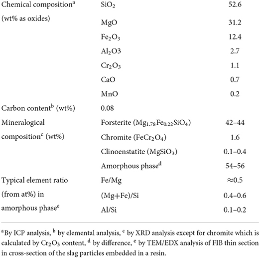
Table 1. Measured chemical and mineralogical composition of SLN ferronickel slags.
Based on the chemical composition presented in Table 1, and considering that the carbonatable elements are Mg, Fe, Mn, and Ca are the ones that can carbonated under the conditions used, the CO2 storage potential of the ferronickel slag is 416 kg of CO2 per ton of slag.
According to XRD analyses, the ferronickel slag is composed of an amorphous phase (around 55 wt%) and a crystalline phase. The latter consists mainly of ferrous forsterite, a natural magnesium silicate of the olivine family, in which some of the magnesium cations are substituted by iron (II) cations. Clinoenstatite is also present in trace amounts and chromite in small quantities. The low crystallinity of this ferronickel slag is explained by its rapid cooling during granulation by quenching, which essentially only allows the crystallization of forsterite, the first crystalline phase to form in the 1,800°C molten slag.
SEM observations of a polished section of resin-coated slag (Figures 2A,B) and TEM diffraction images of a FIB thin section (Figure 2C) show that they are composed of an amorphous matrix (zone C) encompassing massive crystals (zone A) and tapered crystals (zone B) that surround the former. TEM/EDX analysis of these zones shows that the massive crystals are made of ferrous forsterite, whose EDX derived composition Mg1.8Fe0.2SiO4 is a perfect match to that obtained by Rietveld refinement. The tapered crystals have a slightly lower (Mg+Fe)/Si ratio (between 1.4 on their outer fringe and 2 at their core). They could be formed from a mixture of forsterite and enstatite, probably crystallized later during the quenching of the slag by recombination of the forsterite and amorphous phases already present. The amorphous phase presents a (Mg+Fe)/Si ratio around 0.5 and is thus much richer in silicium than the overall slag whose ratio is close to 1. Material balance also confirms the high forsterite content in the slag, estimated at more than 40% by XRD.
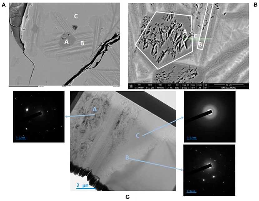
Figure 2. Micrographs of native ferronickel slag cross-sections: (A,B) SEM observations showing FIB cut on (B) (green line), (C) TEM observation of the FIB lamella with diffraction diagrams—(A) ferrous olivine, (B) sticklike mixture of olivine and enstatite, (C) silicium and aluminum-rich amorphous phase.
Thermogravimetric analysis (TGA) of the native slag (cf. Section Carbonation extent) showed negligible mass loss (<0.5 wt%) between 105 and 1,000°C, indicating the absence of hydrated, hydroxylated or carbonated phases.
Before carrying out carbonation tests, the slag was first dry ground using a jar mill. Approximately 500 g of slag are introduced into an alumina jar of dimensions 18.5 × 18.5 cm (D × L). The jar, which is filled with 25, 39 and 60 alumina balls, with diameters 31.8, 18.8 and 9.2 mm, respectively, is rotated at 92 rpm for 4 h. After grinding, the ground product is sieved at 100 μm and the larger size fraction is reground until zero rejection at 100 μm. The volume size distribution of the ground slag is shown in Figure 5. It has a median diameter (dv, 50) of 24.5 μm and a diameter dv, 90 of 79.1 μm (Table 2).
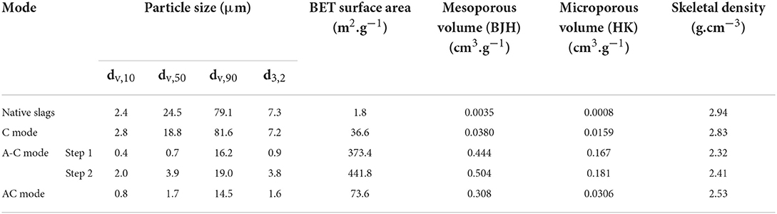
Table 2. Textural properties of ferronickel slag feed and carbonation products from C, A-C and AC modes.
SEM images of the powder (cf. Supplementary Figure S1) show angular particles whose size indeed varies between a few microns and tens of microns. Their surface appears relatively smooth, with few and sparsely deposited submicron fragments.
The Sauter diameter value (d3.2), equal to 7.3 μm, leads to a geometric surface of 0.28 m2/g, while the BET surface measured by gas porosimetry is 1.8 m2/g. The porosity of the slag being negligible (0.004 cm3/g), the surface roughness defined as the ratio between BET and geometric surfaces is 6.5. This value is consistent with values reported by Rimstidt et al. (2012) who indicated forsterite's surface roughness values between 1 and 10, with an average value of 5.4. Finally, the skeletal density of the slag is 2.94 g/cm3, which is slightly lower than that of the forsterite at 3.27 g/cm3 (Anthony et al., 2001).
Carbonation tests were carried out inside a 300 ml autoclave reactor that is fitted with a stirred bead mill impeller (Figure 3). This set-up allows carbonation reactions to be carried out at controlled temperature and pressure in the presence of continuous attrition.
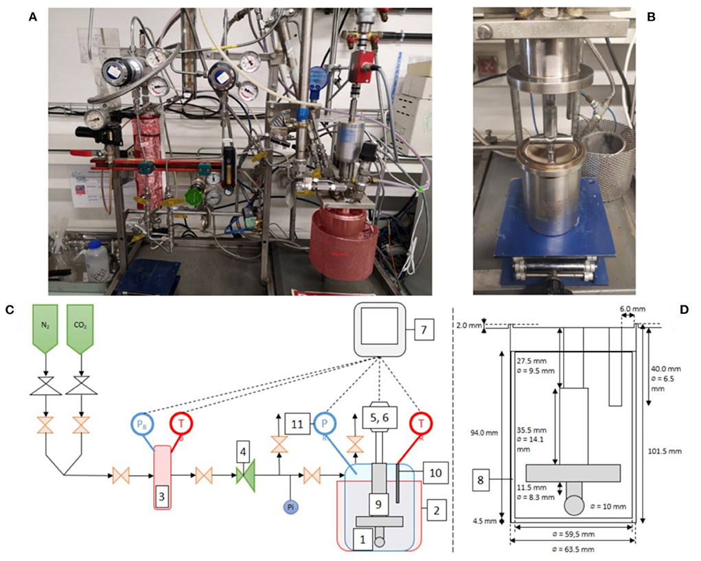
Figure 3. Photographs and schematics of the attrition-carbonation reactor: (A,C) overview and (B,D) detail of the attrition system: (1) Hastelloy® autoclave reactor, (2) annular furnace, (3) gas supply tank with temperature probe and pressure transducer, (4) pressure regulation valve, (5) tachymeter, (6) torque meter, (7) HMI system for control and data acquisition, (8) peek liner, (9) impeller, (10) immersion sleeve with Pt100 probe, (11) pressure transducer.
The Hastelloy® reactor, 60 mm diameter and 100 mm high, is equipped with a peek liner to protect its surface from attrition wear. The temperature in the reactor is measured with a Pt100 probe inserted in a thermowell immersed in the suspension. The reactor is heated by an annular resistor, whose power is controlled by a PID control loop to maintain a constant temperature during the whole reaction time. The pressure in the reactor is measured by a piezo-resistive transmitter (Keller PA-23SY) and is regulated via a pressure regulator connected to a gas tank previously pressurized with CO2 gas. This gas tank, with a volume of 522 ml, is equipped with a precision pressure sensor (Keller PA-33X) and a Pt100 temperature probe, which allow to follow the instantaneous CO2 consumption during a carbonation test. The suspension is agitated using an attrition impeller whose geometry is close to that of Stirred Media Detritors (SMD). It is made of two 60 mm long and 10 mm diameter cylindrical blades. The blades are arranged perpendicularly and 8 mm apart. The bottom of the lower blade sits 3 mm above the bottom of the reactor. The stirring speed and torque are measured with a Kistler 4520A torque sensor, which can be converted into power draw and energy consumption. Typically, the operating system draws 8.2 W under the aqueous carbonation test conditions used. All the instruments are recorded at a 1 Hz sampling rate.
The standard experimental protocol for the carbonation tests is presented hereafter. When variants of this protocol were used, they are described in the corresponding sections (cf. Section Carbonation kinetics and morphological and textural properties of products for different operating modes). The reference test uses a slurry temperature of 150°C and a CO2 partial pressure of 10 bar. Carbonation tests are typically carried out over 24 h, bearing in mind that CO2 consumption is recorded throughout the test duration. Given the objectives of the paper, the operating conditions are not optimized with respect to slurry solids concentration, stirring speed, grinding bead size and mill loading. In particular, the 24 h reaction time is not meant to be the ideal reaction time from a process development perspective; it is merely the duration that was chosen to standardize the testing and study until what point attrition has an effect on the reaction.
The standard experimental protocol uses a slag-in-water suspension containing 9.1 wt% solids. The test procedure is as follows: 540 g of 1 mm diameter yttriated zirconia grinding balls (Netzsch ZetaBeads Plus) are placed in the reactor. Next, 8 grams of ground slag powder are deposited on the surface of the bed of grinding beads and 80 grams of distilled water are added with a wash bottle, ensuring that the powder is well-wetted. The filling level of the reactor is then 68 vol.%. Once closed, the reactor is purged several times with nitrogen in order to eliminate the oxygen present in the gas volume over the slurry, then it is pressurized with ~1 bar of nitrogen. This overpressure avoids the formation of large gas bubbles during the boiling of the water which, when they cross the surface of the slurry, carry away solids which accumulate on the walls of the reactor. The CO2 supply tank is initially filled at a pressure of 35 bar. The slurry is heated to 150°C temperature in half an hour. The CO2 is then introduced into the reactor in order to reach the desired partial pressure, accounting for the partial pressures of nitrogen and water vapor under the conditions used. Typically, the pressure of the N2 and H2O mixture in the reactor is 7 bar at 150°C, to which is added the set partial pressure of 10 bar of CO2. After stabilization of the pressure and temperature inside the supply tank and reactor, which takes about 2 min, the stirring is started at 500 rpm. This corresponds to an impeller tip speed of 1.38 m.s−1. At the end of the test, heating and stirring are stopped, and the reactor is quenched to room temperature in about 30 min by immersion in ice water. The pressure of the gas ceiling is then released to the atmosphere before opening the reactor. The entire reactor content is poured onto a 0.8 mm sieve and rinsed thoroughly with distilled water to separate the grinding beads from the slurry. The internals are carefully rinsed with distilled water to collect all particles and grinding beads stuck on their surface. The amount of distilled water added during this phase, about 1 L, is precisely measured. The cleaning process yields a dilute slurry with <1 wt% solids. Before separating the solids from the process water by high-speed centrifugation, the slurry is stirred inside a glass beaker from which three 2 mL aliquots are syringed out for particle size analysis (cf. Section Particle size distribution). The centrifugation filtrate is collected for chemical analysis and the filtration cake is oven dried for 24 h at 105°C in air. The solid product is finally manually ground in an agate mortar and dry sieved to zero rejection on an 80 μm metal screen before further characterization. Grinding bead wear is evaluated by measuring the dry bead mass before and after testing.
The instantaneous CO2 consumption by the system is calculated from the real-time recording of the CO2 pressure and temperature inside the CO2 supply tank. The number of moles of CO2 consumed by the system is estimated using the Peng-Robinson equation of state. According to the experimental protocol, the system is agitated only once the pressure inside the reactor reaches the set total pressure. Due to the slow gas-liquid transfer in the reactor, it is estimated that the CO2 saturation of the aqueous phase, which is around 10−1 mol.L−1 according to geochemical equilibrium calculations, is reached in about 10 min. It is therefore not possible, under the conditions of carbonation under attrition, to separate CO2 dissolution in water from CO2 consumption by carbonation at the very beginning of the test. This leads to unreliable measurement of the initial carbonation kinetics. Afterwards, CO2 consumption is entirely attributable to the carbonation reaction, and this over the whole test duration. The beginning of the reaction is thus identified by starting from the end point of the recording, i.e., by making the total consumption of CO2 measured at the end of the test coincide with that deduced from the carbonation rate of the material measured by TGA or elemental analysis (cf. next paragraph). This results in the 10 min abovementioned delay between the start of the stirring and the initial time of the reaction thus determined.
As for the starting material, carbonation products were analyzed by a panel of analytical techniques, with the objective of linking their size distribution, morphological properties, elemental composition and mineralogical composition to the attrition and carbonation processes. These different analyses are grouped hereafter according to the type of information they return. Unless otherwise stated, these analyses were performed on the products dried at 105°C and after manual micronization below 80 μm.
Particle size distribution was determined using a Mastersizer 3000 (Malvern Instruments) using a Hydro 3000 dispersion unit (with agitation set at 3500 rpm) and distilled water as the diluent. The refractive index was set at 1.52, which is close to that of silica (Rawle, 2015). As for the absorption index, it is set to 0.1. The obscuration rate used in the analysis is 10%. As earlier mentioned, three 2 mL aliquots are syringed out of the stirred slurry. The sampling procedure was checked for segregation and repeatability. The size distribution is the average of five consecutive measurements performed on the 3 aliquots.
Particles of carbonation products were observed by air-drying a drop of diluted slurry deposited on an aluminum pad. After metallization with platinum, the images are obtained using a SEM-FEG JEOL JSM 7100F TTL microscope operating with an acceleration voltage of 10 kV and at a working distance of 10 mm. Some observations (Figure 6) were also made during the cutting of the FIB sections [cf. Section Electron microscopy (scanning / transmission) coupled with elemental analysis] using an acceleration voltage of 5 kV and a working distance of 4 mm. Transmission electron microscope (TEM) observations were also made using particles from the supernatant liquid obtained after high-speed centrifugation. A drop of supernatant liquid was then placed on a copper grid and dried in ambient air. The particles were observed on a JEOL 2100F microscope using a Gatan RIO16IS CMOS camera, at an acceleration voltage of 200 kV.
The skeletal density of the samples was determined by helium pycnometry with an AccuPyc 1330 (Micromeritics) of a 1 cm3 chamber. Specific surface area (BET) and pore volume were measured with a Belsorp-Max apparatus (Bel Japan) using N2 adsorption at the temperature of 77.4 K on samples weighing about 1.5 g. Before measurement, the samples are degassed under vacuum at 120°C for 10 h using a Belprep-Vac II apparatus (Bel Japan). The mesopore volume is obtained with the BJH method (Barrett et al., 1951) and the micropore volume with the HK method (Horváth and Kawazoe, 1983).
The elemental composition of the native slag was characterized by ICP-OES after total digestion of the material by alkaline fusion. This digestion method consists in making an alkaline glass bead by melting the material at 1,100°C with a flux composed of 35% lithium tetraborate (LiB4O7) and 65% lithium metaborate (LiBO2). The bead produced is then dissolved in a 2 wt% nitric acid solution which is analyzed with an Optima 7000 DV spectrometer (PerkinElmer) to determine the solid's elemental composition. This method of mineralization is preferred to triacid dissolution, which does not reliably dissolve the siliceous phases of the slag, carbonated or not.
In addition to the morphology of the particles/aggregates during the attrition carbonation, electron microscopy coupled with the EDX elemental analysis yields information on the composition of the phases, before and after reaction. Depending on the size of the particles available and the information required (global composition of the phases, nature of the surface layers), different preparations were used. They are described below.
Polished sectionsPolished sections were prepared by mixing native, ground or carbonated slag particles in a slow-setting EpoFix (Stuers) resin. These were then polished manually and with polishing discs using an abrasive paste bearing 3 μm diamond powder. The polished sections were then carbon coated (about 50 nm) in a Leica EM ACE600 high-resolution secondary vacuum evaporator.
Analysis of thin sectionsFIB sections were cut from polished sections in order to quantify the composition of the amorphous phase for both native slag and the carbonation products. It is worth emphasizing that the intimate imbrication of the phases inside native and carbonated slag particles make it impossible to isolate the composition of the amorphous phase from that of the whole material by direct analysis of polished sections with the X-ray microprobe. In addition, in order to examine surface layers caused by carbonation only, a FIB sample was cut out from a product particle obtained by C mode, whose size was close to feed particles. Carbon coating was applied to the samples (polished sections or powder fixed on carbon tape) prior to cutting out FIB sections.
The FIB cut samples were produced using a dual beam SEM-FIB microscope (FEI Helios NanoLab600i) equipped with an EasyLift micromanipulator. The Ga ion source used for the preparation of the thin slides was operated at 30 kV, except for the final “cleaning” phase where voltages between 2 and 5 kV were applied. A 20-nm-thick carbon coating was first deposited using the electron beam on the sample surface (over an area of 20 μm × 2 μm), followed by a 3 μm-thick Pt layer made by ion beam over the same area. The purpose of these two superimposed coatings was to protect the underlying area of interest from the intense currents used during FIB cutting. The particle was partially cut and the micromanipulator tip was glued to the cut via a platinum deposit. The cutout was then lifted out of the sample, then fixed on a copper grid by Pt deposition, and finally released from the tip. Then began the ion beam thinning phase, which used a progressively reduced current from 2.5 nA to 80 pA (under 30 kV). Finally, “cleaning” steps at 5 and 2 kV were performed on each side.
The thin FIB sections were then observed with a JEOL 2100F microscope, using a Gatan RIO16IS CMOS camera in TEM mode. Images were also taken in HAADF STEM mode in order to perform EDX mapping. The spectra and EDX mapping of the areas of interest were obtained using an Ultim Max 80 mm2 windowless analyzer (Oxford Instruments). Images were also taken in diffraction mode to evaluate the crystallinity state of the phases present.
To monitor the progress of the carbonation reaction, the amount of carbonates formed was determined both by thermogravimetric analysis and analysis of their carbon content. It is recalled that the original slag does not show significant mass loss up to 1,000°C (< 0.5%) and a carbon content of only 0.08%.
Thermogravimetric analysisThermograms were obtained on a TGA/DSC 1 - Thermogravimetric Analyzer (Mettler-Toledo). The samples (5 mg) were first heated to 105°C at a constant rate of 10°C/min under nitrogen atmosphere (20 mL.min−1), then maintained at this temperature for 30 min in order to remove moisture. A new temperature increase at 10°C.min−1 to 1,000°C was then performed, still under nitrogen atmosphere. A thermogram was recorded for each product. Preliminary TGA-MS analyses on the carbonated slag (cf. Supplementary Figure S2) showed that carbonates decomposed essentially in the 300–600°C temperature range, while structural water was removed before reaching 300°C.
Elemental analysis of carbonThe carbon content of the solid product was measured on a Perkin Elmer 2400 series II CHNS elemental analyzer, using about 2 mg of powder. These analyses were therefore performed in redundancy with the thermograms in order to validate the measured carbonation yields.
Calculation of the carbonation extentIn concomitant attrition-carbonation or AC mode, a small amount of plastic may contaminate the carbonation product through wear of the peek liner. The extent of this contamination increases the longer the duration of the AC mode experiment, and may lead to an overestimation of the carbonate amount by elemental carbon analysis. This is verified in Supplementary Figure S3, which shows that elemental analysis starts overestimating the actual carbonation extent for samples with 50% and more conversion, which is reached in about 5 h in AC mode.
For attrition followed by carbonation or A-C mode (cf. Section Carbonation kinetics and morphological and textural properties of products for different operating modes), XRD analysis revealed the formation of weakly crystallized montmorillonite and a significant increase in the amount of amorphous phase, which may contribute to the mass loss in the 300–600°C temperature range. Thus, a higher amount of carbonates could be predicted by TGA against elemental C analysis in this case (cf. diamond symbols in Supplementary Figure S3). Montmorillonite was never detected however in AC mode tests under the conditions used.
For these reasons, TGA analysis was the preferred technique for measuring carbonation extent in C mode and AC mode, whereas elemental carbon analysis was used with A-C mode tests.
The carbonation extent is defined as the ratio between the number of moles of carbonates formed and the total number of moles of carbonatable elements, here Mg, Fe, Mn and Ca, contained in the nickel slag.
On the basis of the TGA, it is then calculated using Equation (1):
where minitial and mfinal are respectively the mass of solid before and after reaction, %wt.( TGA loss) the percentage of mass loss measured by TGA in the 300–600°C temperature range, %wt.( j) the initial mass percentage of Mg, Fe, Mn and Ca in the native slag, Mj their molar mass, and MCO2 the molar mass of carbon dioxide (emitted by decomposition of the carbonates present in the sample).
Crystalline phases of the feed material and products were characterized by X-ray diffraction (XRD). These analyses were performed on a Bruker D8 Advance instrument, equipped with a LynxEye XE-TTM detector using a copper X-ray anode (λKα1=15,418 Å), a 40 kV voltage, and a 40 mA intensity. Diffractograms were collected over an angular range of 5° to 70°, with a step size of 0.02° over a total acquisition time of 2.5 h. Crystal phase identification was performed using Bruker-AXS DIFFRACplus Eva v4 software and the ICDD 2015 PDF database. In addition, to obtain a quantitative measurement of the crystalline phases and the total amount of amorphous phases, modeling by the Rietveld method was performed using the DIFFRACplus Topas v5 software (Bruker-AXS). The necessary calibration used the external standard method with zincite, which requires prior knowledge of the elemental composition of the samples analyzed.
Surface analysis of native and carbonated slag was performed by X-ray photoelectron spectrometry (XPS). XPS was used to characterize the atoms present at the extreme surface of the material (first atomic layers) and learn about their immediate chemical environment. Photoelectron emission spectra were recorded on a Thermo Scientific K-Alpha spectrometer, using a monochromatic source with an aluminum anode (hυ = 1486.6 eV) and a spot size of 400 μm.
XPS survey spectra were obtained with a pass energy of 160 eV (1 eV step), and high resolution spectra with a pass energy of 30 eV (0.1 eV step).
The calibration energy of the spectrometer was performed using the reference peaks Au4f7/2 (83.9 ± 0.1 eV) and Cu2p3/2 (932.8 ± 0.1 eV). The XPS spectra were recorded in direct N(Ec) mode and the background signal was subtracted using the Shirley method. A charge compensation system was used during the measurements to neutralize surface charges. These parameters allow the analysis of 400 μm2 surfaces to a depth of < 10 nm. The uncertainty of the measured binding energy values is ±0.1 eV.
As indicated in the introduction, the nature of the carbonation reaction products depends on the composition of the initial phases contained in the feedstock as well as on the operating conditions. Equilibrium calculations were thus performed in order to take into account the complex initial composition of the slag (Table 1) and provide an indication of the expected nature of the stable solid phases. The calculations were performed with the PHREEQC geochemical software and the Thermoddem 2017 database (Blanc et al., 2012; Blanc, 2017), implementing the B-dot model for the calculation of activity coefficients in the aqueous phase. A detailed presentation of the model is available in a previous article (Julcour et al., 2020). Because of the possible inaccuracies in the equilibrium constants describing the solid phases [especially for the challenging clay minerals, as discussed by Blanc et al. (2015)] and the kinetic limits sometimes inhibiting the formation of certain phases, the equilibrium calculations in this complex reactive system were performed on a large PCO2-temperature range.
The resulting predominance diagrams, presented in Supplementary Figure S4, indicate in which solid phase can be included each major element (Si, Mg, Fe, Al). Apart from the main reaction products, namely magnesite (MgCO3), siderite (FeCO3) and amorphous silica (SiO2), it comes that several phyllosilicate phases are likely to form depending on the PCO2-temperature conditions. These phyllosilicates can contain one or several of the major elements Mg, Fe, Al:
- One element in minnesotaite (Fe3Si4O10(OH)2), antigorite (Mg48Si34O85(OH)62) or pyrophyllite (Al2Si4O10(OH)2),
- Two elements in montmorillonite (HcMg) (Mg0.9Al1.4Si4O10(OH)2 ),
- Three elements in saponite (Fe, Mg) (Mg2.17FeAl0.34Si3.66O10(OH)2) and saponite (Mg) (Mg3.17Al0.34Si3.66O10(OH)2).
Each of the phases can be identified by its specific elemental ratios (e.g., Mg/Al, Mg/Si). It can also be noted that each Mg-containing phyllosilicate phase is detrimental to the carbonation process, since it decreases the carbonation yield.
The effectiveness of the concomitant attrition-carbonation or AC mode process for increasing carbonation rate has been reported by several authors (Julcour et al., 2015; Rashid et al., 2019, 2021; Rim et al., 2020). The mechanisms behind this performance gain are not well-understood however, and to the best of our knowledge, there has been no attempt to finely characterize AC mode products, especially with mining waste feedstocks.
In order to validate the relevance of this process for the ferronickel slag used in this study, three experimental protocols were implemented:
- Concomitant attrition and carbonation (AC mode) is performed at 150°C and 10 bar PCO2 for 24 h.
- Carbonation alone (C mode) is performed without grinding media, keeping all other conditions identical to AC mode tests. In particular, this test mode uses the same concentration of solids in the slurry (9.1 wt%) and reactor filling (68 vol.%).
- Attrition followed by carbonation (A-C mode) is carried out by first attriting the slag before proceeding to C mode. The slag is first ground during 24 h in the same configuration as the AC mode, however under 1 bar of nitrogen and at room temperature (step 1). The grinding beads are then separated from the slurry by sieving and rinsing. The solid phase is concentrated by decantation and distilled water is added to the concentrate in order to obtain the desired slurry solids concentration. The slurry is introduced into the reactor emptied of its beads, yielding a filling rate of 31 vol.%, and subjected to carbonation using standard operating conditions (step 2).
A minimum of two tests were performed with each configuration, and unless otherwise stated the results presented in this section are the average of the replicated tests.
The carbonation kinetics obtained with the C, A-C and AC modes are presented in Figure 4, with their 95% confidence interval.
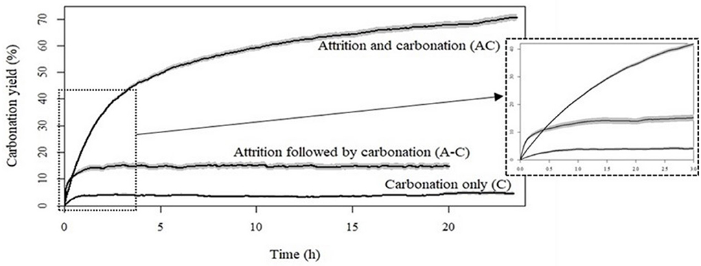
Figure 4. Time variation of carbonation yield for ferronickel slags carbonated under C, A-C, and AC modes.
Analysis of the products obtained after 24 h of reaction shows a carbonation yield of 70% with concomitant attrition and carbonation (AC mode), compared to <5% for carbonation only (C mode) and 15% for the attrition followed by carbonation (A-C) mode (Table 3). Figure 4 shows that the carbonation rate reaches a plateau after about 1 h of reaction in C and A-C modes. Carbonation slows down significantly only beyond 15 h for the AC mode. Even if it seems unlikely, the data collected over a 24-h period does not allow us to completely exclude that the AC mode can achieve a 100% conversion. The insert in Figure 4 shows that the initial carbonation kinetics is fastest with the A-C mode, due to the higher initial specific surface area produced by the preliminary attrition step (Table 2).
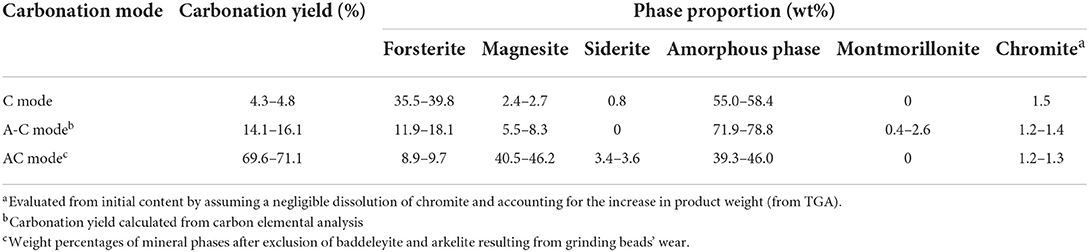
Table 3. Carbonation yields and phase proportions for the carbonated slag in C, A-C, and AC modes.
As highlighted by various authors (Béarat et al., 2006; Daval et al., 2011; Julcour et al., 2015; Gadikota et al., 2020), the early appearance of a plateau in the absence of attrition can be correlated to the formation of product layers on the surface of the unreacted slag particles which inhibit further leaching.
The attrition of unreacted particle surface allows the conversion of ferronickel slag to increase considerably, beyond that of a simple particle size reduction effect. This can be appreciated by comparing the carbonation rates in C and A-C modes. The increase in specific surface of the material from 1.8 to 373 m2.g−1 (Table 2) triples the amount of CO2 sequestered in the material by accelerating the rate of dissolution of the particles relative to the rate of precipitation of the (sub)products at the particle surface. Nevertheless, the latter is inevitable under both conditions and rapidly limits further carbonation reaction, far below the CO2 sequestration potential of the slag particles.
Furthermore, the 200-fold increase in BET surface area caused by attrition before carbonation (Table 2, A-C mode step 1) cannot only be explained by particle size reduction, the Sauter diameter decreasing by a factor 8 only. Thus, the A-C mode leads to a real modification of the surface structure of the material, which is associated with the appearance of mesopores and micropores. Moreover, the skeletal density of the material is also significantly reduced and approaches that of clays, such as montmorillonite or saponite (Anthony et al., 2001). Thus, there appears to be a true mechanochemical effect induced by the grinding beads during attrition alone. Although this effect is difficult to identify when attrition and carbonation are concomitant, it is likely that this phenomenon is present as soon as attrition is operative.
Rigopoulos et al. (2015) also observed a large increase in specific surface area and porosity for olivine-rich basalt particles by wet ball milling. It was also accompanied by an increased adsorption of CO2, but, alike with the A-C mode, in a smaller proportion than the gain in specific surface area. The authors explained this limited benefit by the fact that only some of the defects created in the crystal structure would promote carbonation of the material.
Such textural changes are also visible, but to a much lesser extent, between AC and C modes. In particular, the ratio of micropore to mesopore volumes is 4 times lower for the AC mode than for the two other modes.
This confirms that concomitant carbonation and attrition cannot be reduced to a simple addition of the effects of the separate processes; there is indeed a synergy between the two processes, with a continuous mechanical depassivation of the reactive surface. Further evidence of the mechanical depassivation provided by attrition is presented later in the paper.
It is also interesting to compare the particle size distribution for the products of the three carbonation protocols (Figure 5).
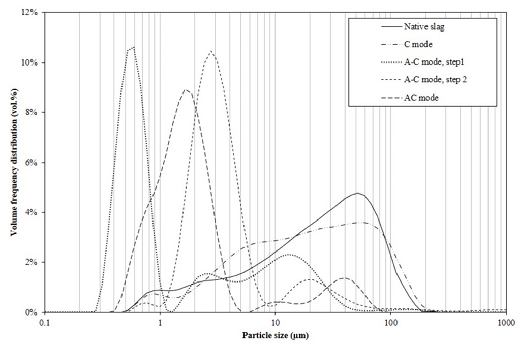
Figure 5. PSD by volume for ferronickel slag feed and carbonation products from C, A-C, and AC modes.
The slag initially ground to a size below 100 μm has a volume median diameter (dv, 50) around 25 μm, with 17 vol.% of the particles below 5 μm and 2.5 vol.% of submicron particles.
Carbonation alone or C mode, with its 5% carbonation yield, modifies the particle size distribution of the slag in a minor way only. Without attrition, the growth of micron sized carbonates contributes to the increase in the proportion of particles between 2 and 10 μm. The 20-fold increase in BET surface area (Table 2) is thus entirely attributable to the layers that formed on the slag particle surface (Figure 6).

Figure 6. SEM images of reaction products from C mode after 24 h of reaction covered with a Si-rich passivation layer: (A) low resolution, (B–D) high resolution (red circle: carbonates).
As for the 24 h pre-attrited slag, it had a sub-micron dv, 50 value, with a main peak centered at 0.6 μm and two secondary modes extending to 40 μm. The latter modes is due to the reagglomeration of the submicronic particles that is known to occur over long stirred milling tests. Indeed, particles from attrition tests conducted under the same conditions but with shorter attrition times (1, 2, and 5 h) are all finer than 10 μm (cf. Supplementary Figure S5). The carbonation of the particles previously attrited for 24 h leads to a significant increase in their average size, with a mode around 3 μm. This increase in average size is attributed to the formation of magnesite and siderite crystals, as well as to the deposition of amorphous silica (and other silicates) on the surface of the slag during dissolution. This can be seen by SEM in Figures 8C,D. Considering the moderate carbonation yield of the slag in A-C mode, these surface layers therefore have a much lower bulk density than the original material, in agreement with the increase in pore volumes measured between the two stages.
Finally, products of the AC configuration have a median size just below 2 μm, just between those from the separate attrition and carbonation steps of the A-C protocol. This intermediate particle size results from a competition between the size decrease due to grinding and the size increase due to the carbonation reaction, both processes occurring here simultaneously. Additional analyses, which will be presented in a forthcoming paper, are underway to quantify and understand the evolution of these competitive efficiencies during a trial in AC mode. SEM-EDX analysis (cf. Supplementary Figure S6) of AC product particles with size centered around 40 μm also showed that they contained mainly product aggregates polymer particles worn from the reactor peek liner.
The composition of the carbonation products, as deduced from the XRD/Rietveld analysis, is presented in Table 3. Whatever the carbonation mode, they contain an amorphous phase, representing between 40 and 80% of their mass, and three major crystalline phases: residual forsterite, magnesite and siderite. TEM/EDX analyses show that these last two phases form in fact a mixed carbonate. The A-C mode also resulted in the formation of low amounts of montmorillonite.
The proportion of residual forsterite, between 9% for the AC mode and 40% for the C mode, decreases with increasing carbonation yield. The formation of carbonates is thus the result of the conversion of forsterite, but also of the native amorphous phase as deduced from mass balance. Indeed, from analysis of the mineral phases present and accounting for the 36% mass uptake estimated from TGA, it is found that 0.016 mole of Mg1.8Fe0.2SiO4 forsterite were converted while 0.056 mole of carbonates were formed in AC mode. During the reaction, the amorphous phase is thus depleted in Mg and Fe to the benefit of Si, contributed to by the neo-formed silica. A-C mode product is distinctively different with a much higher content of amorphous phase than C and AC mode products. This supports the conclusions from several authors (Baláž et al., 2008; Turianicová et al., 2013) that the crystal structure of olivine can be partially disordered by mechanical activation. This activated structure would be composed of amorphous MgO and SiO2 (Turianicová et al., 2013).
As for the A-C mode, we cannot exclude that a continuous mechanical activation also takes place in AC mode and reinforces the beneficial effect of the mechanical depassivation, main engine of the synergy between attrition and carbonation. In A-C mode however, surface amorphization improves carbonation at the start of the reaction only, however its benefit is quickly erased by the formation of surface products.
Table 3 shows that the carbonates Fe/Mg molar ratio is generally lower than that of the original material (Table 1, around 0.2). This suggests the possible presence of iron in the reaction by-products (possibly due to a non-congruent dissolution and/or a partial re-precipitation of iron in phyllosilicate phases as discussed in Section Expected phase formation at thermodynamic equilibrium). The very different composition between A-C and AC mode products is yet another evidence of the synergy between attrition and carbonation processes.
Nickel slags are rich in forsterite, but their main constituent is an amorphous phase that can lead to the formation of specific surface layers. Due to the mineralogical complexity of the slag, it was chosen to combine several of the abovementioned analytical techniques to characterize surface layers: microscopy (SEM, SEM-FIB and TEM) and XPS spectroscopy.
Figure 6 through Figure 8 show SEM images of the products obtained with the three carbonation modes. In the case of Figures 6, 7, the microphotographs correspond to carbonated particles with similar carbonation yields in the range 5–7% obtained with C mode and AC mode, respectively. Given the carbonation efficiency of the AC mode, this required dedicated short AC mode tests that were interrupted after 15 min. Figures 6, 8 compare the products obtained with the three carbonation modes after 24 h of reaction.
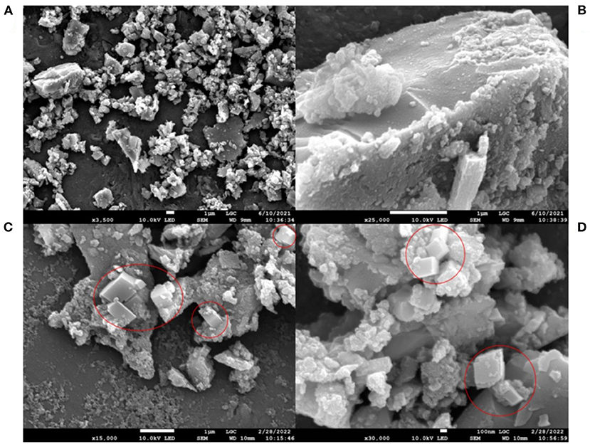
Figure 7. SEM images of reaction products from AC mode after 15 min of reaction partially covered with reaction products: (A,C) low resolution, (B,D) high resolution (red circle: carbonates).
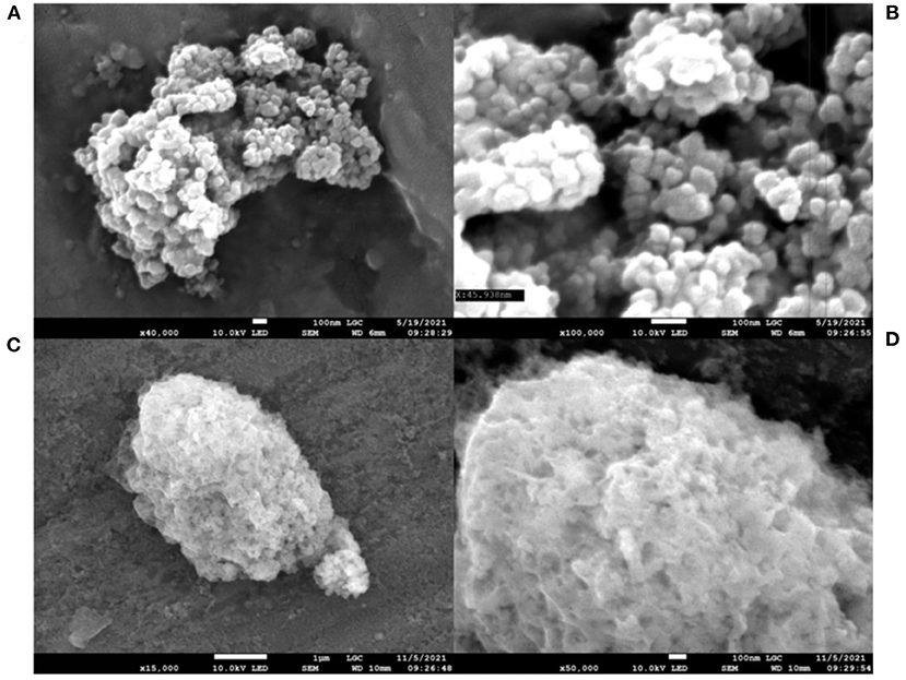
Figure 8. SEM images of reaction products after 24 h of reaction: (A,B) AC mode; (C,D) A-C mode.
In the absence of attrition, the surface of the residual particles is entirely covered by a layer of fibrous-looking products, irrespective of particle size (Figures 6B–D). Disparate carbonate crystals, identified by EDX, of several microns are also observed (Figures 6A,C).
With short reaction time in AC mode (Figure 7), the surface of the residual particles is partially covered by precipitated carbonation reaction products, which form mostly small and separated agglomerates. Carbonates with submicron size are clearly visible (Figures 7C,D). These carbonates are more homogeneously distributed over the surface of the products than in C mode.
After 24 h of carbonation in AC mode, we observe on Figures 8A,B that the particles have lost their angular aspect and that the carbonates are no longer distinguishable on their surface. AC products are micrometric agglomerates formed by clusters of very fine rounded particles of < 100 nm. A-C mode products (Figures 8C,D) also seem to correspond to an agglomeration of elementary particles formed during the preliminary attrition stage (cf. Supplementary Figures S1C,D). They result from the deposition of a phyllosilicate and are clearly distinguishable by their visually spongy aspect.
These observations show once again that beyond their differences in carbonation yield, products obtained with the various carbonation modes exhibit utterly different structures.
TEM images make it possible to evaluate the thickness of the deposition layer formed in C mode. Supplementary Figures S7A,B show that they can reach several hundred nanometers. They also provide information on the structure of the reaction product obtained in AC mode. Supplementary Figures S7C,D, which correspond to very fine particles sampled from the supernatant liquid of the product centrifugation step, all show aggregates of fine elementary particles as seen previously by SEM. Thin sections extracted by FIB however reveal the presence of residual slag cores and carbonates several hundred nanometers in size (Figure 12).
XPS analyses were carried out on three products with low carbonation yields (between 5 and 20%), obtained either from carbonation in C and AC modes. In the latter case, they concern carbonation products obtained after 15 min and 1 h, either at the same carbonation yield as for mode C or at the time for which reaction passivation if is already visible for this carbonation mode. These analyses were also compared to that of native slag.
These analyses correspond to a target zone of 400 μm in diameter over a response depth of < 10 nm, representative of the extreme surface of the particles. They provide both the elemental atomic composition (cf. Supplementary Table S1), and the binding energy levels of the emitted electrons, allowing the determination of the chemical environment to which each detected element is associated (Figure 9).
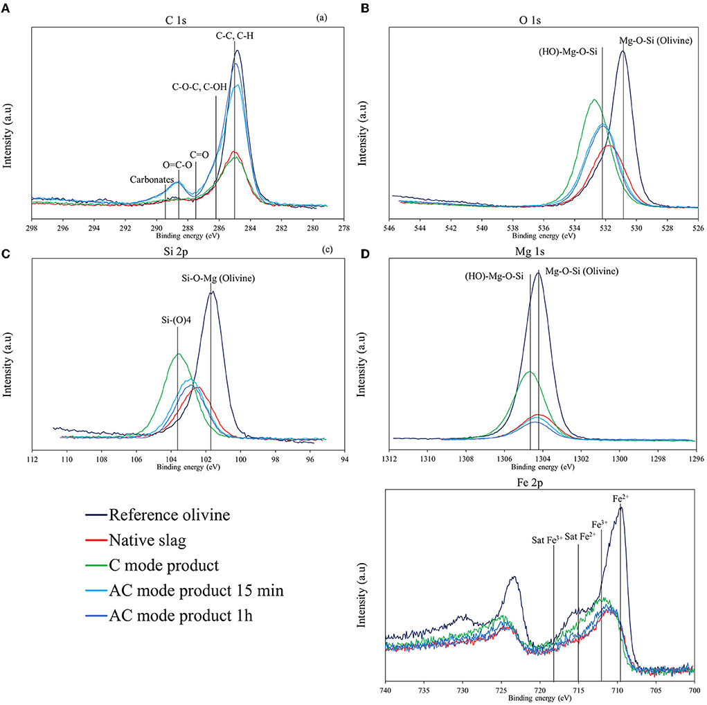
Figure 9. C 1s (A), O 1s (B), Si 2p (C), Mg 1s (D), and Fe 2p (E) XPS spectra of the native ferronickel slags and carbonated products.
Supplementary Table S1 shows that the surface elemental composition is similar for all samples, except for the amount of carbon. The Mg 2s/Si 2p, Fe 2p/Si 2p, O 1s/Si 2p, and Al 2p/Si 2p ratios thus remained fairly close in all three products compared to the native slag (varying in the range 0.40–0.60, 0.10–0.15, 3.1–3.9, and 0.05–0.1), while the C1 s/Si 2p ratio—equal to 1.7 for SLN—turned into 1.1 for the C mode product, but 3.6 and 4.5 for the AC mode products.
The significant presence of carbon detected on the surface of the native slag, which contains <0.1 wt% carbon according to elemental analysis (by combustion), can be explained by the adsorption of CO2 on the surface or an experimental bias due to the use of carbon tape to fix the powder particles. While high resolution C 1s photoemission spectrum (Figure 9A) shows a main peak associated with C-C and C-H bonds due to atmospheric pollution response (adventitious carbon), it also shows a high energy peak (between 288 and 290 eV) with AC mode products that can only be attributed to carbonates (Ardizzone et al., 1997; Shchukarev and Korolkov, 2004). This peak cannot be clearly identified with C mode products however. This can be explained by the fact that carbonates are all or partly covered with by-products on the particle surface and/or are in the form of large crystals too dispersed to be properly sampled, contrary to AC mode where carbonates exhibit small sizes and significantly higher dispersion, as seen in Figure 7. In accordance with increasing carbonation yields, a higher amount of carbon is found in the product obtained after 1 h of carbonation in AC mode compared to that obtained after 15 min (cf. Supplementary Table S1).
Figure 9 also provides the XPS spectra of O 1s, Si 2p, Mg 1s, and Fe 2p. The spectra of a reference olivine (San Carlos olivine) are also shown for comparison. The presence of broad peaks indicates the cohabitation of different chemical environments for these elements in the four samples.
For native slag, the binding energy peak O 1s (Figure 9B) is at 531.8 eV, which is higher than that of a standard olivine (531.2 eV) (Seyama and Soma, 1985; Davoisne et al., 2008). This higher binding energy indicates the presence of more electronegative elements in the vicinity of oxygen atoms, probably due to the silicon-richer amorphous phase. Carbonation products show even higher binding energies for O 1s, of 532.7 eV for the sample from C mode and 532.2 eV for the two 15 min and 1 h samples from AC mode. These values suggest the presence of hydroxyl groups on the surface of the samples (Schulze et al., 2004), particularly for C mode product.
For Si 2p (Figure 9C), the binding energy of the observed peak is 102.5 eV, 102.9 eV, and 103.6 eV, respectively for the native slag and product samples obtained with and without attrition (cf. Supplementary Table S1). These values, around 103.0 eV, are consistent with the presence of silicon contained in a silicate matrix (Moulder et al., 1992). In addition, for C-mode product, the Si 2p peak shifts to the energy peak representative of a Si-(O)4 type silica (Moulder et al., 1992; Elmi et al., 2016), which indicates a silicon enriched surface layer. Conversely, for the two AC mode products, the silicon peak remains close to that of the native slag.
The results in Figure 9D for Mg 1s are in agreement with those for Si 2p, showing peaks obtained at similar energy values (1304.2 and 1304.4 eV) for the native slag and the products from the AC mode. They are also close to that of olivine (1304.0 eV) (Seyama and Soma, 1985). For the carbonation only product, the binding energy for Mg 1s is higher (1304.7 eV), signifying a slight oxidation of magnesium, which indicates the presence of hydroxyl groups in the vicinity of this element.
The Fe 2p spectrum is sensitive to the valence state of iron, leading to peaks located at 711.2 eV for Fe3+ and 709.8 eV for Fe2+, respectively (Davoisne et al., 2008). Beside these main peaks, satellite peaks related to Fe2+ and Fe3+ can be observed at about 715 and 718 eV, respectively (Grosvenor et al., 2004). According to the spectra obtained (Figure 9E), iron is present in both Fe2+ and Fe3+ states in the native slag and carbonated products. However, we can note a slight shift of the main peak toward higher energies for the C mode product: it is located at 711.6 eV against 710.9 eV for the native slag, which seems to indicate a higher degree of oxidation for the iron at the surface of this sample. This observation confirms that not all the iron is in the form of carbonate on the product surface. This corresponds to a small fraction of iron that has oxidized despite the CO2 purge, which is also a loss for carbonation.
For C mode product, the shift of the XPS signals for O 1s, Mg 1s, and Si 2p elements toward the highest binding energies suggests the presence on the surface of a layer of product rich in silica and hydroxyl groups. This could be a Mg3(Si4O10)(OH)2 type phyllosilicate, as shown by the superposition of the O 1s and Mg 1s peaks with the lines representative of such a solid in Figures 9B,D. On the other hand, the similarity in energy profiles between the native slag and AC mode products shows a very similar surface composition for these two samples, which demonstrates that attrition efficiently refreshes the reactive surface during carbonation. The information derived from XPS characterization of the various products provides undeniable evidence of the mechanical depassivation that attrition brings during carbonation.
In order to elucidate more precisely the nature of the passivation layer formed in the absence of attrition, a thin slide cut from a C mode product particle was analyzed by TEM/EDX.
Figure 10 shows that the surface of the particles is covered with a complex 400 nm thick surface layer, which is the cause of passivation and the blockage of any further carbonation. Contrary to what could be observed in the case of forsterite (Béarat et al., 2006; Kwak et al., 2010; Daval et al., 2011; Saldi et al., 2013; Sissmann et al., 2014; Julcour et al., 2015), this surface layer is not homogeneous. Indeed, the main layer is stratified in 5 inner layers with different density and composition, which are all amorphous as shown by local electron diffraction patterns (Figure 10). The elemental composition of these stacked layers is reported in Supplementary Table S2 and Supplementary Figure S8.
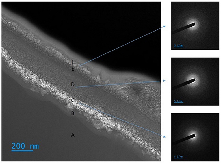
Figure 10. TEM photomicrograph of the surface of a FIB thin section cut out of a C mode product particle, including diffraction images of the different zones.
Zone A corresponds to the native unreacted slag particle. The diffraction image indicates that this zone is also amorphous, but its elemental composition (cf. Supplementary Table S2) is depleted in silicon compared to the initial amorphous phase and is close to that of the overall slag (Table 1).
Moving away from the unreacted core, we observe a transition zone of about 45 nm thickness (zone B) which is enriched in Si and depleted in Mg and Fe, then a zone of granular appearance extending over about 100 nm (zone C), enriched in carbon and also depleted in Mg and Fe. The carbon trapped in this inner layer is thought be partly associated with the nucleation of carbonates on the precipitated silica layer that took place at the beginning of the carbonation reaction.
Next comes a more homogeneous zone about 190 nm thick (zone D), with a composition close to that of zone B, but richer in iron and aluminum.
The following zone, 35 nm thick (zone E), seems to be a transition zone between zone D and the outer layer, with a diffuse aspect and a thickness between 50 to 250 nm (zone F). We also note a significantly higher (Mg+Fe)/Si ratio in this peripheral layer than in the innermost layers (zones B and C), but lower than in the native particle. Its composition is compatible with a Mg-Fe phyllosilicate.
The superposition of these various layers confirms the complex and dynamic character of the surface restructurings that take place during aqueous carbonation of magnesium silicates. We also find thin transition zones (B and E zones) in accord with the dissolution-precipitation mechanism. The very high quantity of carbon in the outermost layer is most certainly due to the deposition of carbon on the surface of the particle before the cutting of the blade and indicates a high porosity of this last layer, which is in agreement with analysis by gas porosimetry (Table 2). Therefore, this layer does not seem to be the cause of the surface passivation. Supplementary Figure S8 shows that D layer blocks the diffusion of the carbon deposited on the surface, and that nucleation of carbonates took place over the C layer. The inhibition of the dissolution is therefore most likely due to a progressive densification of the D layer.
Based on the Mg/Al ratio of the F layer (cf. Supplementary Table S2) and the thermodynamic analysis presented in Section Expected phase formation at thermodynamic equilibrium, this layer could be an amorphous version of saponite.
AC mode productsTo highlight the effect of attrition on the surface of the slag during the aqueous carbonation, a FIB thin section of carbonation products obtained in AC mode after a short time (15 min) was also observed by TEM. Figure 11 shows the product with different magnifications. In addition, X-ray mapping was also carried out to analyse the chemical nature of these products, an example of which is given in Supplementary Figure S9. Despite the lack of representativity of such an observation from a sampling viewpoint, Figure 11A leads to the following observations:
- A residual slag particle several microns in diameter (circled in blue, bottom right). It is composed of an amorphous phase at its core, and two large regions made up of agglomerates of nanometric grains extending from the surface to several hundred nanometers in depth (cf. zoom in Figure 11E). These last zones are polycrystalline (as shown by the ring patterns on the corresponding diffraction images) and have a composition close to that of the core (close to enstatite). They are thus quite distinct from native forsterite and must correspond to reaction/attrition fronts. On the diffraction images, the small distance between the brightest spots on the inner circles could indicate the presence of several crystalline phases. On most of its surface, this native particle is free of passivation layers. Nevertheless, some disparate phyllosilicate deposits can be found on the particle surface (pointed by the purple arrows in Figure 11D).
- Various 1 μm or less particles, different in appearance. EDX mapping reveals that these are reaction products (carbonates (red circled particles) and amorphous alumina-rich silica (particles pointed to by yellow arrows), but also probably fragments of native slag. These smaller particles appear to be covered with phyllosilicate (see purple arrows), indicating that micron sized particles are not efficiently depassivated by the attrition process. Such a limit in the depassivation efficiency of the attrition process in AC mode is to be expected. It depends on the conditions under which attrition is performed, mainly the size of the grinding beads, and is one of the reasons for the measured slowdown in kinetics observed in AC mode, which prevents achieving 100% conversion. Finally, we note that chromium, which is present as chromite in the slag, is found in all the particles (except for the carbonates).
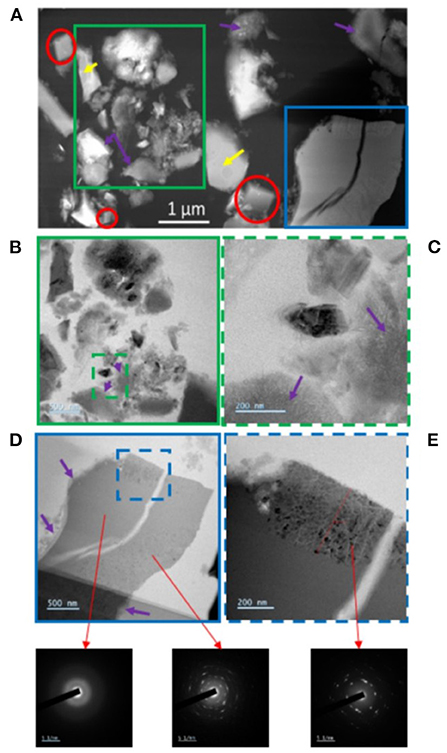
Figure 11. TEM micrograph of a FIB thin section of carbonation products obtained in AC mode after 15 min: (A) overview STEM image, (B,C) zooming of submicron particles, (D,E) zooming of a residual slag particle of a few microns and diffraction images of different characteristic zones (red circles: carbonates, yellow arrows: amorphous silica rich in aluminum, purple arrows: phyllosilicate).
As previously mentioned, the carbonation products after 24 h are mainly composed of aggregates of fine elementary particles. Elemental analysis shows that these particles are an assemblage of grains a few nanometers in size. These grains are made of amorphous silica and carbonates that are dispersed inside a magnesium-depleted alumino-siliceous matrix (cf. Supplementary Figures S10–S14).
Particles larger than 200 nanometers are also found (Figure 12). EDX mapping (cf. Supplementary Figures S13, S14) shows that these are residual native slags, not or only slightly transformed (blue circles) as well as carbonates (red circle).
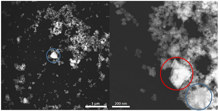
Figure 12. STEM micrograph of a FIB section of carbonation products obtained in AC mode after 24 h (red circle: carbonates, blue circle: residual slag).
In this study, a ferronickel slag composed of an amorphous Mg/Si rich phase and a crystalline ferrous forsterite, was carbonated by direct aqueous carbonation using three distinct operating modes: carbonation alone (C mode), attrition followed by carbonation (A-C mode) and concomitant attrition and carbonation (AC mode). By cross observation of carbonation products using complementary analytical techniques (TGA, elemental analysis, XRD, SEM & TEM/EDX, XPS, gas porosimetry, particle size distribution) and thermodynamic predictions, the work aimed to improve our understanding of passivation during aqueous carbonation of nickel slags, to verify that attrition does lead to beneficial mechanical depassivation during carbonation, and to evaluate the separate and coupled effects of attrition and carbonation. Given the compositional and mineralogical complexity of nickel slags, the main results obtained in this work are expected to apply to non-thermally activatable magnesium silicate carbonation feedstocks.
The following paragraphs summarize the main conclusions from the work presented in this paper.
• With aqueous carbonation only (C mode), slag particles reached a full passivation in 1 hour with a 5% carbonation yield. Analysis of the products revealed the presence of secondary phases deposited on the particle surface. Theses phases form a complex amorphous layer stratified in several inner layers, which differs from reported observations of passivated forsterite particles that usually exhibit a homogeneous layer. The peripheral zone is both meso- and micro-porous and its composition is similar to that of a saponite, which is consistent with geochemical simulation. However, the observations lead us to conclude that this layer is not at the origin of the surface passivation. The stopping of the dissolution is rather due to a progressive densification of the internal deposit layers.
• With attrition prior to carbonation (A-C mode), slag particles did also passivate in 1 h at a 15% carbonation yield. While this operating mode decreased significantly the size of the slag particles as expected, reducing their Sauter diameter from 7.2 to 0.9 μm, it was found that attrition profoundly alters the particles' microstructure. In particular, the attrited microstructure exhibited increased quantity of amorphous phase with meso- and micro-porosity. This pre-carbonation mechanochemical activation however was found to be only slightly beneficial to the subsequent carbonation, and total passivation was reached in the same time (1 h) as with C mode. The evidence of the mechanochemical effect of attrition on the slag particles suggests, however, that it must also play a role in AC mode, even if its effect cannot be differentiated from other concomitant processes in this mode.
• With concomitant attrition and carbonation (AC mode), slag particles never undergo a complete passivation, yielding 35% carbonation in 2 h, 50% in 5 h, and more than 70% in 24 h. XPS analyses of AC mode products after 1 h of reaction show that the surface composition of AC products is that of native slag particles. This observation is reinforced by SEM observation of AC products after 15 min of reaction, which show large particles without any passivation layer when such fresh particles are not observed in C mode. These observations bring conclusive evidence that attrition indeed depassivates slag particles during the carbonation process, this mechanical depassivation being mainly responsible for the high carbonation yield obtained with nickel slag.
• TEM analysis of the particles after a short reaction time also shows that the attrition causes a profound structural modification of the surface of the slag particles over a thickness of several hundreds of nanometers, creating a porous zone with crystalline nanoparticles. This effect is not sufficient for A-C mode to yield high carbonation yields, but its combined effect with mechanical depassivation is probably at the origin of the high performance of carbonation in AC mode.
• The phyllosilicate that is observed in C mode is also observed on the surface of submicron particles in AC mode, as well as on the agglomerated nanoparticles that surround residual cores. The deposition of this phyllosilicate is very likely to be responsible for the progressive slowing down of AC mode carbonation kinetics after several hours of reaction. This observation leads to conclude that the depassivation brought by attrition, as it is operated in this work, prevents surface passivation up to a point where particles are too small. Whether it is possible to delay the decline in attrition depassivation efficiency is an important issue that requires further investigation, one option being to reduce the size of all or part of the grinding beads.
• Carbonation of nickel slags using AC mode produces very characteristic products: they consist in agglomerates a few microns in size formed by bound spherical particles in the tens of nanometers size range. These particles are themselves constituted by an entanglement of nanometric grains of carbonates and amorphous silica inside a magnesium-depleted alumino-siliceous matrix, with unreacted cores observable at their center. This combined micro- and nano-scale microstructure is the direct result of concomitant processes that are caused by the coupled attrition and carbonation processes. Research is underway to understand the pathway that leads to the formation of these complex structures, based on observation of carbonation products in AC mode at various times over the 24 h test period used in this paper. It is hoped that this additional knowledge will help derive enhanced carbonation kinetics pathways, which remains one of the main issues for deployment of mineral carbonation value chains with magnesium silicates.
The raw data supporting the conclusions of this article will be made available by the authors, without undue reservation.
AD, CJ, and FB wrote the first draft of the manuscript, which was revised, read, and approved by all other authors.
This work is part of an ongoing multi-disciplinary research effort co-funded by the New Caledonian Energy Agency ACE (grant #CS17-3160-00) and the French Agency for Ecological Transition (grant #1894C0021).
The authors would like to recognize the invaluable contributions of the following persons: Bruno Boyer, Jean-Louis Labat, Alec Maunoury, Quentin Ribière, and Lahcen Farhi from ST LGC for the design, commissioning and operation of the carbonation reactor system; Christine Rey-Rouch, Gwenaëlle Guittier and Marie-Line de Solan from SAP LGC for the characterization of the products; Birsen Budan from LMDC for the XRD/Rietveld analysis; Armel Descamps-Mandine and Claudie Josse from Raimond Castaing Centre (Université Paul Sabatier – Toulouse III) for the SEM/TEM observations and Alexandre Freulon from CIRIMAT laboratory for his assistance with the making of polished sections.
The authors declare that the research was conducted in the absence of any commercial or financial relationships that could be construed as a potential conflict of interest.
All claims expressed in this article are solely those of the authors and do not necessarily represent those of their affiliated organizations, or those of the publisher, the editors and the reviewers. Any product that may be evaluated in this article, or claim that may be made by its manufacturer, is not guaranteed or endorsed by the publisher.
The Supplementary Material for this article can be found online at: https://www.frontiersin.org/articles/10.3389/fclim.2022.946735/full#supplementary-material
Anthony, J. W., Bideaux, R. A., Bladh, K. W., and Nichols, M. C. (2001). Handbook of Mineralogy, Vol. 1, 20151–1110. Chantilly, VA: Mineralogical Society of America.
Ardizzone, S., Bianchi, C., Fadoni, M., and Vercelli, B. (1997). Magnesium salts and oxide: an XPS overview. Appl. Surf. Sci. 119, 253–259. doi: 10.1016/S0169-4332(97)00180-3
Baláž, P., Turianicová, E., Fabián, M., Kleiv, R. A., Briančin, J., Obut, A., et al. (2008). Structural changes in olivine (Mg, Fe)2SiO4 mechanically activated in high-energy mills. Int J Miner Process. 88, 1–6. doi: 10.1016/j.minpro.2008.04.001
Barrett, E. P., Joyner, L. G., and Halenda, P. P. (1951). The determination of pore volume and area distributions in porous substances. I. Computations from nitrogen isotherms. J. Am. Chem. Soc. 73, 373–380. doi: 10.1021/ja01145a126
Béarat, H., McKelvy, M. J., Chizmeshya, A. V. G., Gormley, D., Nunez, R., Carpenter, R. W., et al. (2006). Carbon sequestration via aqueous olivine mineral carbonation: role of passivating layer formation. Environ. Sci. Technol. 40, 4802–4808. doi: 10.1021/es0523340
Blanc, P. (2017). “Thermoddem: update for the 2017 version,” in Report BRGM/RP-66811-FR. Available online at: https://thermoddem.brgm.fr/sites/default/files/upload/documents/brgmrp-66811-fr_final_report_0.pdf
Blanc, P., Lassin, A., Piantone, P., Azaroual, M., Jacquemet, N., Fabbri, A., et al. (2012). Thermoddem: a geochemical database focused on low temperature water/rock interactions and waste materials. Appl. Geochem. 27, 2107–2116. doi: 10.1016/j.apgeochem.2012.06.002
Blanc, P., Vieillard, P., Gailhanou, H., Gaboreau, S., Gaucher, É., Fialips, C. I., et al. (2015). A generalized model for predicting the thermodynamic properties of clay minerals. Am. J. Sci. 315, 734–780. doi: 10.2475/08.2015.02
Brent, G., Rayson, M., Kennedy, E., Stockenhuber, M., Collins, W., Prigge, J., et al. (2015). “Mineral carbonation of serpentinite: from the laboratory to pilot scale—the MCi Project,” in Proceedings of the 5th International Conference on Accelerated Carbonation for Environmental and Material Engineering ACEME (New York, NY).
Casey, W. H., Westrich, H. R., Massis, T., Banfield, J. F., and Arnold, G. W. (1989). The surface of labradorite feldspar after acid hydrolysis. Chem. Geol. 78, 205–218. doi: 10.1016/0009-2541(89)90058-2
Chizmeshya, A. V., McKelvy, M. J., Squires, K., Carpenter, R. W., and Béarat, H. (2007). A Novel Approach to Mineral Carbonation: Enhancing Carbonation While Avoiding Mineral Pretreatment Process Cost. Tempe, AZ: Arizona State Univ.
Daval, D., Martinez, I., Corvisier, J., Findling, N., Goffé, B., Guyot, F., et al. (2009). Carbonation of Ca-bearing silicates, the case of wollastonite: experimental investigations and kinetic modeling. Chem. Geol. 265, 63–78. doi: 10.1016/j.chemgeo.2009.01.022
Daval, D., Sissmann, O., Menguy, N., Saldi, G. D., Guyot, F., Martinez, I., et al. (2011). Influence of amorphous silica layer formation on the dissolution rate of olivine at 90°C and elevated pCO2. Chem. Geol. 284,193–209. doi: 10.1016/j.chemgeo.2011.02.021
Davoisne, C., Leroux, H., Frère, M., Gimblot, J., Gengembre, L., Djouadi, Z., et al. (2008). Chemical and morphological evolution of a silicate surface under low-energy ion irradiation. Astron. Astrophys. 482, 541–548. doi: 10.1051/0004-6361:20078964
Di Lorenzo, F., Ruiz-Agudo, C., Ibañez-Velasco, A., Millán, G. S., Navarro, J. A., Ruiz-Agudo, E., et al. (2018). The carbonation of wollastonite: a model reaction to test natural and biomimetic catalysts for enhanced CO2 sequestration. Minerals 8, 209. doi: 10.3390/min8050209
Ding, W., Fu, L., Ouyang, J., and Yang, H. (2014). CO2 mineral sequestration by wollastonite carbonation. Phys Chem Miner. 41, 489–496. doi: 10.1007/s00269-014-0659-z
Dlugogorski, B. Z., and Balucan, R. D. (2014). Dehydroxylation of serpentine minerals: implications for mineral carbonation. Renew. Sustain. Energy Rev. 31, 353–367. doi: 10.1016/j.rser.2013.11.002
Doucet, F. J. (2011). Scoping Study on CO2 Mineralization Technologies. Council for Geoscience, Report No CGS-2011-007, Pretoria, South Africa.
Du Breuil, C., César-Pasquier, L., Dipple, G., Blais, J. F., Iliuta, M. C., Mercier, G., et al. (2019). Mineralogical transformations of heated serpentine and their impact on dissolution during aqueous-phase mineral carbonation reaction in flue gas conditions. Minerals 9, 680. doi: 10.3390/min9110680
Elmi, C., Guggenheim, S., and Gieré, R. (2016). Surface crystal chemistry of phyllosilicates using X-ray photoelectron spectroscopy: A review. Clays Clay Miner. 64, 537–551. doi: 10.1346/CCMN.2016.064033
Gadikota, G., Fricker, K., Jang, S. H., and Park, A. H. A. (2015). “Carbonation of silicate minerals and industrial wastes and their potential use as sustainable construction materials,” in Advances in CO2 Capture, Sequestration, and Conversion (Washington, DC: American Chemical Society), 295–322. doi: 10.1021/bk-2015-1194.ch012
Gadikota, G., Matter, J., Kelemen, P., Brady, P. V., and Park, A. H. A. (2020). Elucidating the differences in the carbon mineralization behaviors of calcium and magnesium bearing alumino-silicates and magnesium silicates for CO2 storage. Fuel 277, 117900. doi: 10.1016/j.fuel.2020.117900
Gerdemann, S. J., O'Connor, W. K., Dahlin, D. C., Penner, L. R., and Rush, H. (2007). Ex situ aqueous mineral carbonation. Environ. Sci. Technol. 41, 2587–2593. doi: 10.1021/es0619253
Grosvenor, A., Kobe, B., Biesinger, M., and McIntyre, N. (2004). Investigation of multiplet splitting of Fe 2p XPS spectra and bonding in iron compounds. Surf. Interface Anal. Int. J Devoted Dev. Appl. Tech. Anal. Surf. Interfaces Thin Films 36, 1564–1574. doi: 10.1002/sia.1984
Guermech, S., Mocellin, J., Tran, L.-.H, Mercier, G., and Pasquier, L.-C. A. (2022). study of hydromagnesite and nesquehonite precipitation in indirect aqueous carbonation of thermally-activated serpentine in a batch mode. J. Cryst. Growth 584, 126540. doi: 10.1016/j.jcrysgro.2022.126540
Guning, P., and Hills, C. (2014). “Carbon negative: First commercial application of accelerated carbonation technology,” in Proceedings of the 7th International Scientific Conference: Science and Higher Education in Function of Sustainable Development (Uzice).
Hariharan, S., and Mazzotti, M. (2017). Kinetics of flue gas CO2 mineralization processes using partially dehydroxylated lizardite. Chem. Eng. J. 324, 397–413. doi: 10.1016/j.cej.2017.05.040
Hellmann, R., Wirth, R., Daval, D., Barnes, J. P., Penisson, J. M., Tisserand, D., et al. (2012). Unifying natural and laboratory chemical weathering with interfacial dissolution–reprecipitation: a study based on the nanometer-scale chemistry of fluid–silicate interfaces. Chem. Geol. 294, 203–216. doi: 10.1016/j.chemgeo.2011.12.002
Horváth, G., and Kawazoe, K. (1983). Method for the calculation of effective pore size distribution in molecular sieve carbon. J. Chem. Eng. Jpn. 16, 470–475. doi: 10.1252/jcej.16.470
Huijgen, W. J., Witkamp, G. J., and Comans, R. N. (2005). Mineral CO2 sequestration by steel slag carbonation. Environ. Sci. Technol. 39, 9676–9682. doi: 10.1021/es050795f
Huijgen, W. J., Witkamp, G. J., and Comans, R. N. (2006). Mechanisms of aqueous wollastonite carbonation as a possible CO2 sequestration process. Chem. Eng. Sci. 61, 4242–4251. doi: 10.1016/j.ces.2006.01.048
Huijgen, W. J. J., and Comans, R. N. J. (2003). Carbon Dioxide Sequestration by Mineral Carbonation Literature Review, Report ECN-C–03-016. Energy Research Centre of the Netherlands ECN, Petten, Netherlands. p. 52. Available online at: https://repository.tno.nl//islandora/object/uuid:54e58547-a814-48f7-b809-5ef1f5af0b03
Johnson, N. C., Thomas, B., Maher, K., Rosenbauer, R. J., Bird, D., Brown Jr, G. E., et al. (2014). Olivine dissolution and carbonation under conditions relevant for in situ carbon storage. Chem. Geol. 373, 93–105. doi: 10.1016/j.chemgeo.2014.02.026
Julcour, C., Bourgeois, F., Bonfils, B., Benhamed, I., Guyot, F., Bodénan, F., et al. (2015). Development of an attrition-leaching hybrid process for direct aqueous mineral carbonation. Chem. Eng. J. 262, 716–726. doi: 10.1016/j.cej.2014.10.031
Julcour, C., Cassayre, L., Benhamed, I., Diouani, J., and Bourgeois, F. (2020). Insights into nickel slag carbonation in a stirred bead mill. Front. Chem. Eng. 2, 588579. doi: 10.3389/fceng.2020.588579
Kwak, J. H., Hu, J. Z., Hoyt, D. W., Sears, J. A., Wang, C., Rosso, K. M., et al. (2010). Metal carbonation of forsterite in supercritical CO2 and H2O using solid state 29Si, 13C NMR spectroscopy. J. Phys. Chem. C 114, 4126–4134. doi: 10.1021/jp1001308
Lackner, K. S., Wendt, C. H., Butt, D. P., Joyce, E. L. Jr., and Sharp, D. H. (1995). Carbon dioxide disposal in carbonate minerals. Energy 20, 1153–1170. doi: 10.1016/0360-5442(95)00071-N
Lackner, K. S. A. (2003). guide to CO2 sequestration. Science 300, 1677–1678. doi: 10.1126/science.1079033
Li, Z., Guo, J., Dong, Z., and Chen, J. (2018). Insight into interactions of olivine-scCO2-water system at 140° C and 15 MPa during CO2 mineral sequestration. Geosci Front. 9, 1945–1955. doi: 10.1016/j.gsf.2017.12.008
McKelvy, M. J., Chizmeshya, A. V., Diefenbacher, J., Béarat, H., and Wolf, G. (2004). Exploration of the role of heat activation in enhancing serpentine carbon sequestration reactions. Environ. Sci. Technol. 38, 6897–6903. doi: 10.1021/es049473m
Meyer, V., de Cristofaro, N., Bryant, J., and Sahu, S. (2018). Solidia cement an example of carbon capture and utilization. Key Eng. Mater. 761, 197–203. doi: 10.4028/www.scientific.net/KEM.761.197
Min, Y., Li, Q., Voltolini, M., Kneafsey, T., and Jun, Y. S. (2017). Wollastonite carbonation in water-bearing supercritical CO2: effects of particle size. Environ. Sci. Technol. 51, 13044–13053. doi: 10.1021/acs.est.7b04475
Monasterio-Guillot, L., Fernandez-Martinez, A., Ruiz-Agudo, E., and Rodriguez-Navarro, C. (2021a). Carbonation of calcium-magnesium pyroxenes: physical-chemical controls and effects of reaction-driven fracturing. Geochim. Cosmochim. Acta. 304, 258–280. doi: 10.1016/j.gca.2021.02.016
Monasterio-Guillot, L., Rodriguez-Navarro, C., and Ruiz-Agudo, E. (2021b). Kinetics and mechanisms of acid-pH weathering of pyroxenes. Geochem. Geophys. Geosyst. 22, e2021GC009711. doi: 10.1029/2021GC009711
Monkman, S., and Shao, Y. (2010). Integration of carbon sequestration into curing process of precast concrete. Can J Civ Eng. 37, 302–310. doi: 10.1139/L09-140
Moulder, J. F., Stickle, W. F., Sobol, P. E., Bomben, K. D., and Chastain, J. (1992). Handbook of X-ray Photoelectron Spectroscopy. Eden Prairie, MN: Physical Electronics. Inc.
O'Connor, W. K., Dahlin, D. C., Nilsen, D. N., Rush, G. E., Walters, R. P., Turner, P. C., et al. (2001). Carbon dioxide Sequestration by Direct Mineral Carbonation: Results From Recent Studies and Current Status. Albany, OR: Albany Research Center (ARC),
Park, A. H. A., and Fan, L. S. (2004). CO2 mineral sequestration: physically activated dissolution of serpentine and pH swing process. Chem. Eng. Sci. 59, 5241–5247. doi: 10.1016/j.ces.2004.09.008
Pasquier, L. C., Mercier, G., Blais, J. F., Cecchi, E., and Kentish, S. (2014). Parameters optimization for direct flue gas CO2 capture and sequestration by aqueous mineral carbonation using activated serpentinite based mining residue. Appl. Geochem. 50,66–73. doi: 10.1016/j.apgeochem.2014.08.008
Penner, L., O'Connor, W. K., Dahlin, D. C., Gerdemann, S., and Rush, G. E. (2004). Mineral Carbonation: Energy Costs of Pretreatment Options and Insights Gained from Flow Loop Reaction Studies. US DOE, DOE/ARC-TR-04–042.
Rashid, M. I., Benhelal, E., Farhang, F., Oliver, T. K., Rayson, M. S., Brent, G. F., et al. (2019). Development of Concurrent grinding for application in aqueous mineral carbonation. J. Clean. Prod. 212, 151–161. doi: 10.1016/j.jclepro.2018.11.189
Rashid, M. I., Benhelal, E., Farhang, F., Oliver, T. K., Stockenhuber, M., Kennedy, E. M., et al. (2021). Application of concurrent grinding in direct aqueous carbonation of magnesium silicates. J CO2 Util. 48, 101516. doi: 10.1016/j.jcou.2021.101516
Rawle, A. F. (2015). Best practice in laser diffraction–a robustness study of the optical properties of silica. Proc. Eng. 102, 182–189. doi: 10.1016/j.proeng.2015.01.124
Rigopoulos, I., Petallidou, K. C., Vasiliades, M. A., Delimitis, A., Ioannou, I., Efstathiou, A. M., et al. (2015). Carbon dioxide storage in olivine basalts: effect of ball milling process. Powder Technol. 273, 220–229. doi: 10.1016/j.powtec.2014.12.046
Rim, G., Wang, D., Rayson, M., Brent, G., and Park, A. H. A. (2020). Investigation on abrasion versus fragmentation of the si-rich passivation layer for enhanced carbon mineralization via CO2 partial pressure swing. Ind. Eng. Chem. Res. 59, 6517–6531. doi: 10.1021/acs.iecr.9b07050
Rimstidt, J. D., Brantley, S. L., and Olsen, A. A. (2012). Systematic review of forsterite dissolution rate data. Geochim. Cosmochim. Acta. 99, 159–178. doi: 10.1016/j.gca.2012.09.019
Ruiz-Agudo, E., Putnis, C. V., Rodriguez-Navarro, C., and Putnis, A. (2012). Mechanism of leached layer formation during chemical weathering of silicate minerals. Geology 40, 947–950. doi: 10.1130/G33339.1
Saldi, G. D., Daval, D., Morvan, G., and Knauss, K. G. (2013). The role of Fe and redox conditions in olivine carbonation rates: an experimental study of the rate limiting reactions at 90 and 150 C in open and closed systems. Geochim. Cosmochim. Acta. 118, 157–183. doi: 10.1016/j.gca.2013.04.029
Saldi, G. D., Jordan, G., Schott, J., and Oelkers, E. H. (2009). Magnesite growth rates as a function of temperature and saturation state. Geochim. Cosmochim. Acta. 73, 5646–5657. doi: 10.1016/j.gca.2009.06.035
Sanna, A., Uibu, M., Caramanna, G., Kuusik, R., and Maroto-Valer, M. M. (2014). A review of mineral carbonation technologies to sequester CO2. Chem. Soc. Rev. 43,8049–8080. doi: 10.1039/C4CS00035H
Schott, J., and Berner, R. A. (1983). X-ray photoelectron studies of the mechanism of iron silicate dissolution during weathering. Geochim. Cosmochim. Acta. 47, 2233–2240. doi: 10.1016/0016-7037(83)90046-7
Schott, J., Pokrovsky, O. S., Spalla, O., Devreux, F., Gloter, A., Mielczarski, J. A., et al. (2012). Formation, growth and transformation of leached layers during silicate minerals dissolution: the example of wollastonite. Geochim. Cosmochim. Acta. 98, 259–281. doi: 10.1016/j.gca.2012.09.030
Schulze, R. K., Hill, M. A., Field, R. D., Papin, P. A., Hanrahan, R. J., Byler, D. D., et al. (2004). Characterization of carbonated serpentine using XPS and TEM. Energy Convers. Manag. 45, 3169–3179. doi: 10.1016/j.enconman.2004.02.003
Seyama, H., and Soma, M. (1985). Bonding-state characterization of the constitutent elements of silicate minerals by X-ray photoelectron spectroscopy. J. Chem. Soc. Faraday Trans. 1 Phys. Chem. Condens. Phases 81, 485–495. doi: 10.1039/f19858100485
Shchukarev, A., and Korolkov, D. (2004). XPS study of group IA carbonates. Cent. Eur. J. Chem. 2, 347–362. doi: 10.2478/BF02475578
Sissmann, O., Brunet, F., Martinez, I., Guyot, F., Verlaguet, A., Pinquier, Y., et al. (2014). Enhanced olivine carbonation within a basalt as compared to single-phase experiments: reevaluating the potential of CO2 mineral sequestration. Environ. Sci. Technol. 48, 5512–5519. doi: 10.1021/es405508a
Turianicová, E., Baláž, P., Tuček, L., Zorkovská, A., Zelenák, V., Németh, Z., et al. (2013). A comparison of the reactivity of activated and non-activated olivine with CO2. Int. J. Miner. Process 123, 73–77. doi: 10.1016/j.minpro.2013.05.006
Velbel, M. A. (1993). Formation of protective surface layers during silicate-mineral weathering under well-leached, oxidizing conditions. Am. Mineral 78, 405–414.
Wang, F., Dreisinger, D., Jarvis, M., and Hitchins, T. (2019). Kinetics and mechanism of mineral carbonation of olivine for CO2 sequestration. Miner. Eng. 131, 185–197. doi: 10.1016/j.mineng.2018.11.024
Wang, F., Dreisinger, D. B., Jarvis, M., and Hitchins, T. (2018). The technology of CO2 sequestration by mineral carbonation: current status and future prospects. Can. Metall. Q. 57, 46–58. doi: 10.1080/00084433.2017.1375221
Werner, M., Hariharan, S., and Mazzotti, M. (2014). Flue gas CO 2 mineralization using thermally activated serpentine: from single-to double-step carbonation. Phys. Chem. Chem. Phys. 16, 24978–24993. doi: 10.1039/C4CP02786H
Werner, M., Hariharan, S. B., Bortolan, A. V., Zingaretti, D., Baciocchi, R., Mazzotti, M., et al. (2013). Carbonation of activated serpentine for direct flue gas mineralization. Energy Proc. 37, 5929–5937. doi: 10.1016/j.egypro.2013.06.519
Yadav, S., and Mehra, A. (2021). A review on ex situ mineral carbonation. Environ. Sci. Pollut. Res. 28, 12202–12231. doi: 10.1007/s11356-020-12049-4
Keywords: CO2 utilization, direct aqueous mineral carbonation, concomitant attrition and carbonation, stirred bead mill, magnesium silicates, silica-rich layers, ferronickel slags, industrial wastes
Citation: Dufourny A, Julcour C, Esvan J, Cassayre L, Laniesse P and Bourgeois F (2022) Observation of the depassivation effect of attrition on magnesium silicates' direct aqueous carbonation products. Front. Clim. 4:946735. doi: 10.3389/fclim.2022.946735
Received: 17 May 2022; Accepted: 15 July 2022;
Published: 04 August 2022.
Edited by:
Binoy K. Saikia, North East Institute of Science and Technology (CSIR), IndiaReviewed by:
Muhammad Imran Rashid, University of Engineering and Technology, Lahore, PakistanCopyright © 2022 Dufourny, Julcour, Esvan, Cassayre, Laniesse and Bourgeois. This is an open-access article distributed under the terms of the Creative Commons Attribution License (CC BY). The use, distribution or reproduction in other forums is permitted, provided the original author(s) and the copyright owner(s) are credited and that the original publication in this journal is cited, in accordance with accepted academic practice. No use, distribution or reproduction is permitted which does not comply with these terms.
*Correspondence: Florent Bourgeois, ZmxvcmVudC5ib3VyZ2VvaXNAdG91bG91c2UtaW5wLmZy
Disclaimer: All claims expressed in this article are solely those of the authors and do not necessarily represent those of their affiliated organizations, or those of the publisher, the editors and the reviewers. Any product that may be evaluated in this article or claim that may be made by its manufacturer is not guaranteed or endorsed by the publisher.
Research integrity at Frontiers
Learn more about the work of our research integrity team to safeguard the quality of each article we publish.