- 1College of Mining Engineering, College of Materials Science and Engineering, North China University of Science and Technology, Tangshan, China
- 2Tangshan Guoliang Special Refractory Limited Company, Postdoctoral Workstation, Tangshan, China
Carbon nanotubes (CNTs) had potential applications in energy conversion and storage devices, and it could be prepared by expanded graphite loaded with catalyst at high temperature, however, the mechanism of carbon nanotube growth in expanded graphite need further confirmation. In this work, carbon nanotubes’ in situ growth in expanded graphite (EG) were prepared via catalytic pyrolysis reaction using carbores P as a carbon source and Co(NO3)3•6H2O as a catalyst. The results of X-ray diffraction (XRD), scanning electron microscope (SEM) and energy dispersive X-ray spectroscope (EDS) indicated the carbon nanotubes could generate in, EG with the presence of carbores P as a carbon source and cobalt nitrate as a catalyst. More interestingly, the growth mechanism of carbon nanotubes could be concluded by the results of differential thermal analysis-thermogravimetry-mass spectrometry (DTA-TG-MS) and X-ray photoelectron spectroscopy (XPS) analysis. The pyrolysis products of carbores P were mainly hydrocarbon gas such as CH4 gas, which reacts with Co(NO3)3·6H2O catalyst to reduces CoOx to Co particles, then the carbon form pyrolysis was deposited the on the surface catalyst Co particles and, after continuous solid dissolution and precipitation, carbon nanotubes were at last generated in EG at last.
1 Introduction
Expanded graphite (EG) was first prepared in the early 1860s by mixing natural graphite with strong oxidants (Xing et al., 2022). EG possesses a loose and porous vermicular morphology, which leads to a large surface area. Hence, the expanded graphite is also named worm graphite. Expanded graphite as a kind of remarkable and new carbon material has excellent corrosion resistance, high temperature resistance, high thermal conductivity, a light weight, good adsorption, and insulation resistance. Therefore, it has been widely used in the fields of hydrogen storage, fuel cells, sensors, catalysts, adsorbents, medicine, and refractories (Yang et al., 2011; Li et al., 2013; Li et al., 2010; Qi et al., 2010).
Taking the application of, EG in refractories as an example, Shantanu K Behera blended Al2O3-C slide gate plate refractories using expanded graphite as the C source (Behera and Mishra, 2015). Apart from positive oxidation resistance, the refractories exhibited good hot and cold strength as well. In 2015, Wang researched the effect of the reactivity and porous structure of, EG on microstructures and the properties of Al2O3-C refractories (Wang et al., 2015). The results showed that the mechanical properties and oxidation resistance of the Al2O3-C refractories had been improved via the addition of, EG. Subsequently, Wang synthesized a boron- and nitrogen-doped expanded graphite as efficient reinforcement for Al2O3-C refractories (Wang et al., 2017). Analogously, they also studied Al2O3-C refractories using silicon hybridized expanded graphite as an addition to enhance their mechanical properties (Wang et al., 2018). In addition, the MgO-C refractories containing expanded graphite were investigated for their thermo-mechanical properties and oxidation resistance (Zhu et al., 2013; Subham Mahato and Behera, 2014; Mahato and Behera, 2016).
Some researches found that CNTs could be formed in refractory materials containing expanded graphite. Furthermore, the composites of CNTs and expanded graphite have the significance of synergistic toughening for refractory materials. Ming Luo et al. researched the Al2O3-C refractories containing CNTs, and found that the mechanical properties, such as the cold modulus of rupture and flexural modulus, were better than that of the materials without the CNTs (Luo et al., 2013). Similarly, Ming Luo et al. investigated carbon nanotubes in situ and ceramic whiskers in Al2O3-C refractories with the addition of Ni-catalyzed phenolic resin. The results also indicated that the formation of the CNTs and the ceramic whiskers lead to the enhancement of mechanical properties (Luo et al., 2012a). Additionally, Ming Luo et al. thought that the strength and toughness of refractory materials could be enhanced via introducing the CNTs/EG (Luo et al., 2012b).
Up to now, chemical vapor deposition has been widely used in the growth of carbon nanotubes in expanded graphite. Expanded graphite loaded with catalyst is heated at a high temperature, and the catalyst on its surface would react with hydrocarbon gases such as acetylene to form carbon nanotubes in expanded graphite. For example, Jianguo Zhao et al. prepared carbon nanotubes in the pores of expanded graphite via chemical vapor deposition using acetylene as the carbon source (Zhao et al., 2009). In addition, Baoyan Xing et al. successfully prepared CNTs in, EG through the in situ synthesis method by selecting naphthalene as the carbon source (Xing et al., 2022). Although the carbon source for carbon nanotubes growth in expanded graphite has generated great interest, the growth mechanism of carbon nanotubes has rarely been proven by experimental methods.
Carbores P is a carbonaceous powder with very high coking yield and softening point (>220°C), and it provides binder properties for resin-bonded magnesia-carbon (MgO-C) or dolomite bricks and alumina-carbon (Al2O3-C) refractories. And Carbores P was suited for use as a precursor of CNTs.
More interestingly, CNTs have a large surface area, enabling increased electrochemical accessibility and mechanical, chemical, and electrochemical stability, which creates the potential for CNTs to be used as a supplemental material for energy conversion and storage devices (Iqbal et al., 2019).
In this work, the cheap carbores P was used as a carbon source and Co(NO3)2•6H2O as a catalyst to form carbon nanotubes in expanded graphite through catalytic pyrolysis reaction, and argon was used as a protective atmosphere. The feasibility of the catalytic cleavage of carbores P to form carbon nanotubes was investigated, and the growth mechanism of the carbon nanotubes is discussed.
2 Materials and methods
2.1 Synthesis of CNTs in EG
Carbores P was taken as the carbon source. Co(NO3)3•6H2O was used as the catalyst that was 1.0 wt% of expanded graphite. Firstly, the expanded graphite and the catalyst Co(NO3)3 water solution were thoroughly mixed, and were placed in a corundum crucible post drying. Then, graphite paper was placed in the corundum crucible. After that, carbores P was put on the graphite paper and then heated to 550°C in a furnace using argon as a protective atmosphere. Next, the flowing argon was closed, and the sample continue to be heated at 1,100°C for 3 h at a rate of 3°C/min and then cooled down with the furnace. The scheme of the reactor setup is shown in Figure 1. The sample was classified into three types, as listed in Table 1.
2.2 Characterization
The phase composition of all samples was analyzed by D/MAX2500PC X-ray diffractometer (XRD). The scanning angle and scanning speed were 10–80° and 10°/min, respectively. The radiation source target of the diffractometer was the Cu-target Kα. The S-4800 field emission scanning electron microscope was equipped with an energy dispersive spectrometer (EDS) and was used to observe the morphology of the synthetic sample and the quantity of sample. Differential thermal analysis-thermogravimetry-mass spectrometry (DTA-TG-MS, NETZSCH STA 449F5, Germany) of the sample was carried out. The chemical state was tested by X-ray photoelectron spectroscopy (XPS, PHI5300C, United States).
3 Results and discussion
3.1 Phase analysis
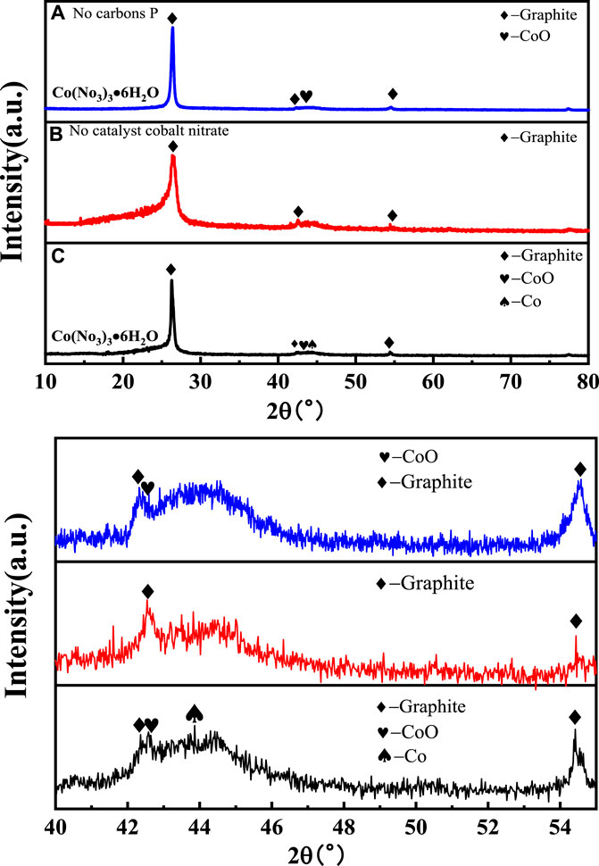
The phase composition of all samples was analyzed by XRD, and the results are presented in Figure 2. All samples showed a strong diffraction peak at 26.5°, which is a typical feature of the (002) crystal plane diffraction of graphitic material. There was a visible CoO phase in samples 1 and 3. Sample 3 had a sharper peak corresponding to the (200) plane of the CoO phase than that of sample 1. It could be obtained from the local magnification figure that there was a trace phase of the cobalt metal according with 44.2° in sample 3. It is reasonable that the phase differences of those samples should be related to the change of the Co element in the catalyst Co(NO3)3•6H2O during the catalytic process (Ince Yardimci et al., 2020; Saconsint et al. et al., 2022).
3.2 Microstructure analysis
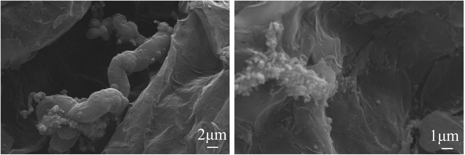
The SEM images of sample 1 are shown in Figure 3. The, EG maintained a loose and vermicular morphology. Obviously, the CNT was not generated between the clearance in the, EG but granular material had been there, and the Co element and C element existed in Sample 1 according to the result of energy dispersive spectroscopy (EDS) analysis. It could be concluded that CNTs could not generate under the condition of the Co(NO3)3·6H2O catalyst without carbores P.
The SEM images of sample 2 are shown in Figure 4. The irregular precipitate formed between the pores of expanded graphite. Without the Co(NO3)3·6H2O catalyst, the carbon nanotubes were not formed instead of the granules precipitate, which indicated the CNTs were not sufficiently grown in the sample without a Co(NO3)3·6H2O catalyst but with carbores P.
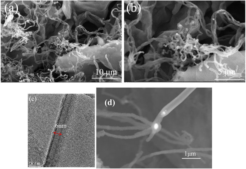
The SEM and transmission electron microscopy (TEM) images of sample 3 are shown in Figure 5. There were a lot of curly fibers between the pores of expanded graphite, and the fibers were hollow and about 6 nm, which are carbon nanotubes (CNTs). In addition, the catalyst cobalt was located at the top of the carbon nanotubes, which lead to the formation of carbon nanotubes radially. As shown in Figure 5C, the nanotubes were typical of carbon nanotubes (CNTs) with a hollow structure.
3.3 Thermal decomposition of carbores P and expanded graphite
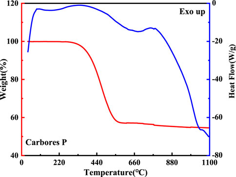
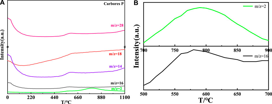
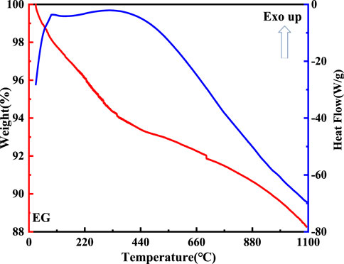
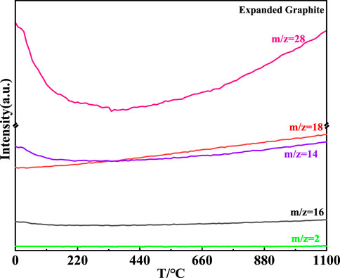
The thermal decomposition process of carbores P and expanded graphite was surveyed by DTA-TG-MS, and is shown in Figures 6–9.
The DTA-TG curve of carbores P is shown in Figure 6. Firstly, there were three endothermic peaks which were located at 168°C, 340°C, and 800°C in the DTA curve. This indicated that gas production started and the carbon began to resolve, as the TG curve showed a weight change from 97% to 57% between 340°C and 558°C. This phenomenon verified that the carbon source from the carbores P had decomposed to generate the gas.
The MS curve of carbores P is shown in Figure 7 (a). It could be concluded that the CH4, H2O, CO, and H2 gas corresponding to the m/z = 16, m/z = 18, m/z = 28, and m/z = 2, respectively, were generated at 558°C (Efimova et al., 2010; Hotová and Slovák, 2016), which was same as the TG-DTA curve. Interestingly, the local magnification of H2 showed that the H2 was produced at 700°C–900°C. Additionally, the MS curve of the CH4 gas presented distinct fluctuations in the local magnification. Similarly, in comparison with the DTA-TG curve, the MS curve was slightly undulating at 800°C. Through the comprehensive analysis of the MS and TG curves, it was found that carbores P began to produce CH4, H2O, CO, and H2 gas in this process.
The DTA-TG curve of the expanded graphite is shown in Figure 8. As for the DTA curve, reaction peaks formed at 100°C and 420°C. This indicated that volatile matter began to escape from the expanded graphite at 100°C. Additionally, it was remarkable that the weight of the expanded graphite changed from 100% to 88% in the TG curve due to its continuous decomposition.
The MS curve of the expanded graphite is shown in Figure 9. It could be concluded that the H2O and CO were generated with the continuous rise of temperature corresponding to the m/z = 18 and m/z = 28, respectively (Chien and Liao, 2020; Guo et al., 2022). Compared with the MS curve of carbores P, the intensity of the CO and CO2 generated in carbores P was more intense than that of the expanded graphite. Additionally, the production of the CH4 and H2 gases were not observed in, EG corresponding to the MS curve. The CH4 and H2 gases were actually involved in the reaction with the catalyst cobalt to form the growth of the CNTs, which demonstrated that the growth of the CNTs depended on the carbores P instead of the, EG. The results of the MS curve of the, EG was consistent with the SEM of the samples.
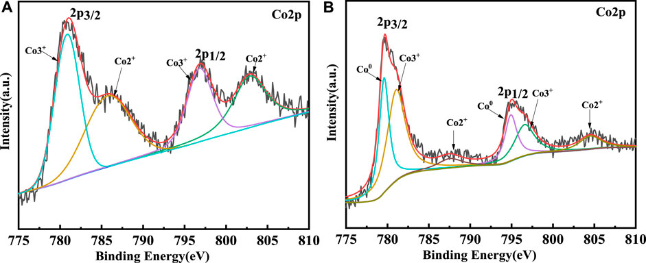
3.4 Valence analysis of Co
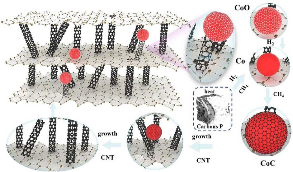
The XPS was used to survey the valency of Co which would be changed in catalytic process. The XPS survey results of sample 1 and sample 3 are shown in Figure 10. Firstly, for sample 1, the curve could be fitted by two spin-orbit doublet characteristics of Co3+ and Co2+ in the XPS narrow survey of Co2p (Yang et al., 2019; Gao et al., 2021). Thus, there were four peaks corresponding to two valence states of Co, which were located at 780.6 eV and 796.8 eV and could be ascribed to Co3+, while the peaks located at 785.7 eV and 803 eV were attributed to Co2+. However, the Co 2p spectrum of sample 3 could be fitted in six peaks. The signals located at 779.9 eV and 794.8 eV could be attributed to 2p 3/2 and 2p 1/2 of Co0, respectively. The two peaks of 781.2 eV and 796.8 eV could be ascribed to the Co3+. The peaks at 787.9 eV and 804.7 eV could be assigned to Co2+. Through the contrastive XPS surveys of sample 1 and sample 3, it is worth mentioning that Co0 existed in sample 3. In general, in the process of CNT growth, Co3+ and Co2+ are reduced into metallic cobalt, which is reduced by the H2 gas. Thus, the Co0 could be detected in the sample 3. Additionally, Co2p1/2 was produced by CoO, which indicated the Co-O band existed (Liu et al., 2021). The results of the XPS coincided with the CNT growth mechanism. In theory, the growth process of CNTs could be revealed by Equations 1, (2). Firstly, the CoO is reduced by H2 to generate Co particles. Then, the Co particles react with the CH4 to generate CoC. At this time, the concentration of C atoms on the surface of the CoC is larger than the concentration of C atoms on the surface on the, EG. Thus, the C atoms should continuously spread due to the concentration difference of C atoms. The concentration difference of C atoms leads to the growth of CNTs. The schematic of the CNT growth mechanism is shown in Figure 11.
3.5 Growth mechanism of CNTs
The schematic illustration of the CNT growth mechanism in, EG is shown in Figure 12. As is well known, the growth mechanism of carbon nanotubes for the synthesis of hydrocarbons from transition metal catalyzed thermal decomposition is not very clear, and the side emphasis of their accounts is different. This can be summarized as the “dissolution diffusion precipitation” model. Firstly, the carbon after the decomposition of hydrocarbons contacts with the bare metal surface. After that, dissolved carbon diffuses, disperses, and is transported to other sites of metal particles. Finally, carbon is deposited and precipitated at these site in the form of carbon nanotubes.
In this work, carbores P was used as the source of the C element. First of all, the expanded graphite was heated from room temperature to 1,100°C. In this process, many oxygenated functional groups were generated on the surface of the graphite crystal and, when the expanded graphite was heated to an elevated temperature, most of the oxygenated functional groups were decomposed into CO2 or H2O, leaving the high energy unsaturated carbon dangling bonds on the surface of expanded graphite. These unsaturated carbon dangling bonds became the active sites. At the same time, carbores P cleaved to produce hydrocarbon gases such as methane and hydrogen gas at an elevated temperature. Subsequently, the hydrogen gas reduced CoO to Co particles. Next, the CoO reacted with the CH4 to generate the CoC. The C atom contacted with the CoC and dissolved, adsorbed on the active sites of expanded graphite. Additionally, dissolved supersaturated carbon diffused in the CoC and was transported to other sites of the CoC. Ultimately, the concentration of C atoms on the surface of the CoC was larger than the concentration of C atoms on the surface on the, EG. The C atoms should continuously spread at these sites to generate carbon nanotubes. Then, the catalyst particles gradually became inactive and the carbon nanotubes stopped growing.
4 Conclusion
CNTs successfully grew in, EG with the synergistic effect of carbores P and the Co(NO3)3·6H2O catalyst. The growth mechanism of carbon nanotubes was that the heated carbores P produces hydrocarbon gas (methane and hydrogen gas), which reacted with the Co(NO3)3·6H2O catalyst to reduce CoOx to Co particles, then the carbon form pyrolysis was deposited the on the surface catalyst Co particles, after continuous solid dissolution and precipitation, carbon nanotubes were at last generated in the, EG.
Data availability statement
The original contributions presented in the study are included in the article, further inquiries can be directed to the corresponding author.
Author contributions
YW: Writing–original draft. WZ: Methodology, Writing–review and editing. YC: Writing–review and editing. XZ: Investigation, Writing–review and editing. JH: Methodology, Writing–original draft. HW: Investigation, Writing–original draft. JT: Formal Analysis, Writing–review and editing.
Funding
The author(s) declare financial support was received for the research, authorship, and/or publication of this article. This work was financially supported by the Natural Science Foundation of Hebei Province of China (Grant No. E2017209164) and Tangshan New High Temperature Materials Innovation Consortium Capacity Enhancement Project (Grant No. 22150239J).
Conflict of interest
Authors YW, XZ, and JH were employed by Tangshan Guoliang Special Refractory Limited Company.
The remaining authors declare that the research was conducted in the absence of any commercial or financial relationships that could be construed as a potential conflict of interest.
Publisher’s note
All claims expressed in this article are solely those of the authors and do not necessarily represent those of their affiliated organizations, or those of the publisher, the editors and the reviewers. Any product that may be evaluated in this article, or claim that may be made by its manufacturer, is not guaranteed or endorsed by the publisher.
References
Behera, S. K., and Mishra, B. (2015). Strengthening of Al2O3-C slide gate plate refractories with expanded graphite. Ceram. Int. 41, 4254–4259. doi:10.1016/j.ceramint.2014.11.092
Chien, A. C., and Liao, B. Y. (2020). Oscillating syngas production on NiO/YSZ catalyst from methane oxidation. RSC Adv. 10, 26693–26698. doi:10.1039/d0ra02051f
Efimova, O. S., Khokhlova, G. P., and Patrakov, Y. F. (2010). Thermal conversion of coal-tar pitch in the presence of silicon compounds. Solid Fuel Chem. 44, 5–11. doi:10.3103/s0361521910010027
Gao, H., Liu, Y., Ma, Y., Meng, E., and Zhang, Y. (2021). Synthesis of N-doped Co@C/CNT materials based on ZIF-67 and their electrocatalytic performance for oxygen reduction. Ionics 27, 2561–2569. doi:10.1007/s11581-021-04031-y
Guo, T., Zhang, R., Wang, X., Kong, L., Xu, J., Xiao, H., et al. (2022). Porous structure of beta-cyclodextrin for CO(2) capture: structural remodeling by thermal activation. Molecules 27, 7375. doi:10.3390/molecules27217375
Hotová, G., and Slovák, V. (2016). Quantitative TG-MS analysis of evolved gases during the thermal decomposition of carbon containing solids. Thermochim. Acta. 632, 23–28. doi:10.1016/j.tca.2016.03.012
Ince Yardimci, A., TanoGlu, M., Yilmaz, S., and Selamet, Y. (2020). Effect of CNT incorporation on PAN/PPy nanofibers synthesized by electrospinning method. Turk. J. Chem. 44, 1002–1015. doi:10.3906/kim-1911-49
Iqbal, S., Khatoon, H., Hussain Pandit, A., and Ahmad, S. (2019). Recent development of carbon based materials for energy storage devices. Mater. Sci. Energy Technol. 2, 417–428. doi:10.1016/j.mset.2019.04.006
Li, L. X., Song, Z. W., Shi, X. K., Kang, W. Z., Zhang, H. J., and Zhao, H. L. (2013). Research progress and development of expanded graphite in water pollution control. Adv. Mater. Res. 777, 43–46. doi:10.4028/www.scientific.net/AMR.777.43
Li, M. J., Lai, Q., and Li, Y. F. (2010). The study on the preparation of expanded graphite by fine squama graphite. Adv. Mater. Res. 113-116, 1610–1613. doi:10.4028/www.scientific.net/AMR.113-116.1610
Liu, Y., Li, Y., Wu, Q., Su, Z., Wang, B., Chen, Y., et al. (2021). Hollow CoP/FeP(4) heterostructural nanorods interwoven by CNT as a highly efficient electrocatalyst for oxygen evolution reactions. Nanomater. (Basel) 11, 1450. doi:10.3390/nano11061450
Luo, M., Li, Y., Jin, S., Sang, S., Zhao, L., Wang, Q., et al. (2013). Microstructure and mechanical properties of multi-walled carbon nanotubes containing Al2O3–C refractories with addition of polycarbosilane. Ceram. Int. 39, 4831–4838. doi:10.1016/j.ceramint.2012.11.075
Luo, M., Li, Y., Jin, S., Sang, S., Zhao, L., and Li, Y. (2012b). Microstructures and mechanical properties of Al2O3-C refractories with addition of multi-walled carbon nanotubes. Mater. Sci. Eng. A 548, 134–141. doi:10.1016/j.msea.2012.04.001
Luo, M., Li, Y., Sang, S., Zhao, L., Jin, S., and Li, Y. (2012a). In situ formation of carbon nanotubes and ceramic whiskers in Al2O3–C refractories with addition of Ni-catalyzed phenolic resin. Mater. Sci. Eng. A 558, 533–542. doi:10.1016/j.msea.2012.08.044
Mahato, S., and Behera, S. K. (2016). Oxidation resistance and microstructural evolution in MgO–C refractories with expanded graphite. Ceram. Int. 42, 7611–7619. doi:10.1016/j.ceramint.2016.01.169
Saconsint, S., Sae-tang, N., Srifa, A., Koo-Amornpattana, W., Assabumrungrat, S., Fukuhara, C., et al. (2022). Development of high-performance nickel-based catalysts for production of hydrogen and carbon nanotubes from biogas. Sci. Rep. 12, 15195. doi:10.1038/s41598-022-19638-y
Subham Mahato, S. K. P., Behera, S. K., and Behera, S. K. (2014). Fabrication and properties of MgO–C refractories improved with expanded graphite. Ceram. Int. 40, 16535–16542. doi:10.1016/j.ceramint.2014.08.007
Wang, Q., Li, Y., Jin, S., Sang, S., Xu, Y., Xu, X., et al. (2018). Enhanced mechanical properties of Al2O3-C refractories with silicon hybridized expanded graphite. Mater. Sci. Eng. A 709, 160–171. doi:10.1016/j.msea.2017.10.046
Wang, Q., Li, Y., Liao, N., Xu, X., Sang, S., Xu, Y., et al. (2017). Synthesis of boron and nitrogen-doped expanded graphite as efficient reinforcement for Al2O3-C refractories. Ceram. Int. 43, 16710–16721. doi:10.1016/j.ceramint.2017.09.063
Wang, Q., Li, Y., Sang, S., and Jin, S. (2015). Effect of the reactivity and porous structure of expanded graphite (EG) on microstructure and properties of Al2O3–C refractories. J. Alloys Compd. 645, 388–397. doi:10.1016/j.jallcom.2015.05.124
Xing, B., Zhao, J., Ren, Y., Pan, Q., Song, J., Han, P., et al. (2022). Hybrid composite materials generated via growth of carbon nanotubes in expanded graphite pores using a microwave technique. Inorg. Chem. Commun. 137, 109185. doi:10.1016/j.inoche.2021.109185
Yang, H., Zhu, M., Guo, X., Yan, C., and Lin, S. (2019). Anchoring MnCo(2)O(4) nanorods from bimetal-organic framework on rGO for high-performance oxygen evolution and reduction reaction. ACS Omega 4, 22325–22331. doi:10.1021/acsomega.9b02362
Yang, Y. F., Zhang, X. J., and Xu, X. (2011). Preparation and characteristics of expanded graphite. Adv. Mater. Res. 189-193, 2695–2698. doi:10.4028/www.scientific.net/AMR.189-193.2695
Zhao, J., Guo, Q., Shi, J., Liu, L., Jia, J., Liu, Y., et al. (2009). Carbon nanotube growth in the pores of expanded graphite by chemical vapor deposition. Carbon 47, 1747–1751. doi:10.1016/j.carbon.2009.02.028
Keywords: carbon nanotubes, catalytic pyrolysis, DTA-TG-MS, growth mechanism, expanded graphite (EG)
Citation: Wang Y, Zhang W, Chen Y, Zeng X, Huang J, Wei H and Tu J (2023) Mechanism of carbon nanotube growth in expanded graphite via catalytic pyrolysis reaction using carbores P as a carbon source. Front. Chem. 11:1260099. doi: 10.3389/fchem.2023.1260099
Received: 17 July 2023; Accepted: 25 September 2023;
Published: 19 October 2023.
Edited by:
Tao Wang, Nanjing University of Aeronautics and Astronautics, ChinaReviewed by:
Donggai Ding, Xi’an University of Architecture and Technology, ChinaLihong Gao, Beijing Institute of Technology, China
Xingtao Xu, Zhejiang Ocean University, China
Copyright © 2023 Wang, Zhang, Chen, Zeng, Huang, Wei and Tu. This is an open-access article distributed under the terms of the Creative Commons Attribution License (CC BY). The use, distribution or reproduction in other forums is permitted, provided the original author(s) and the copyright owner(s) are credited and that the original publication in this journal is cited, in accordance with accepted academic practice. No use, distribution or reproduction is permitted which does not comply with these terms.
*Correspondence: Yuejun Chen, Y2hlbnl1ZWp1bjIwMDVAMTYzLmNvbQ==
 Yilong Wang1,2
 Yuejun Chen

