 Ziyi Hao1,2
 Kaiyue Zhu
- 1State Key Laboratory of Catalysis, Dalian Institute of Chemical Physics, Chinese Academy of Sciences, Dalian, Liaoning, China
- 2Department of Chemistry, University of California, Los Angeles, Los Angeles, CA, United States
- 3Department of Chemical Physics, University of Science and Technology of China, Hefei, China
Searching for stable cathodes is of paramount importance to the commercial development of low-cost and safe aqueous Zn-ion batteries (AZIBs). V2O3 is a good candidate for AZIB cathodes but has unsatisfied cycling stability. Herein, we solve the stability issue of a V2O3 cathode by coating a robust carbon shell. Strong evidence was provided that V2O3 was oxidized to favorable V2O5·nH2O during charging and the carbon shell could promote the oxidation of V2O3 to V2O5·nH2O. The discharge capacity was increased from ∼45 mA h g−1 to 336 mA h g−1 after V2O3 was oxidized to V2O5·nH2O, indicating a higher Zn2+-storage capability of V2O5·nH2O than V2O3. In addition, the rate-capability and long-term cycling performance are greatly enhanced after coating carbon shells on the surface of V2O3 nanorods. Therefore, the presented strategy of introducing carbon shells and fundamental insights into the favorable role of carbon shells in this study contribute to the advancement of highly stable AZIBs.
1 Introduction
In the past few decades, organic lithium-ion batteries (LIBs) have been widely used to power small-scale portable consumer electronics such as laptops and cellphones. However, further penetration of organic LIBs into the large-scale energy-storage (LSES) market is hindered by concerns over operational safety and cost, primarily due to the use of flammable organic electrolytes and expensive electrode materials (Tarascon and Armand, 2001; Yang et al., 2011). In contrast, aqueous LIBs attract much attention in terms of non-flammability, high ionic conductivity, and low cost, although they are characterized by low energy density and poor stability due to the narrow voltage window, high Li+ diffusion barriers, and the interference of unfavorable H+ intercalation (Bin et al., 2018; Wan et al., 2019; Posada-Pérez et al., 2021). As a promising alternative, rechargeable aqueous Zn-ion batteries (AZIBs) based on safe, non-toxic, and low-cost aqueous electrolytes are ideally suitable for LSES applications (Ming et al., 2019; Zhang N. et al., 2020; Chao et al., 2020). Moreover, compared to organic LIBs, the higher ionic conductivity (∼1 S cm−1 vs. ∼1–10 mS cm−1) and air tolerance of aqueous electrolytes enable a faster discharge/charge rate and easier assembly (Song et al., 2018; Blanc et al., 2020). Compared to aqueous LIBs, the high stability of zinc metal (Zn/Zn2+: 0.763 vs. standard hydrogen electrode) in water and air shows that Zn metal can be directly used as the anode of the AZIB, possessing high capacity and excellent cycling performance (Song et al., 2018; Wang F. et al., 2021; Wang X. et al., 2021).
Aqueous Zn-ion batteries (AZIBs), which consist of a Zn anode, a Zn2+/H+ storage cathode, and a Zn2+-salt electrolyte, hold great potential to meet the capacity, power, cost, and safety requirement of LSES owing to the following unique merits (Tang et al., 2019; Zhu et al., 2020b). First, the suitable redox potential (−0.76 V vs. standard hydrogen electrode (SHE)) of Zn/Zn2+ enables earth-abundant Zn metal to be directly used as the anode in AZIBs, thus contributing to a high theoretical capacity (820 mA h g−1/5,855 mA h cm−3). Second, the mildly near-neutral electrolyte (such as ZnSO4 and Zn(CF3SO3)2) can mitigate Zn-dendrite formation and endows ZIBs with good cycling stability. Moreover, good compatibility with water and air of Zn, together with the nontoxicity of the components enable ZIBs with facile fabrication and excellent recyclability.
Compared to the Zn plating/stripping at the anode, the unfavorable insertion/extraction behavior of Zn2+/H+ at the cathode determines the electrochemical properties (e.g., capacity and cycling stability) of AZIBs due to the strong electrostatic interactions between the divalent Zn2+ and the host lattice of cathode materials (Fang et al., 2018; Ming et al., 2018; Song et al., 2018; Liang et al., 2019; Jia et al., 2020). To address the issues, the recent development of AZIBs has been mostly focused on exploiting cathode materials with high capacity and cycling stability, together with elucidating the electrochemical mechanisms.
V-compounds are promising cathode materials for AZIBs because they feature unique open-layered or tunnel structures, which allow Zn2+/H+ or molecules to be inserted into the layers or tunnels (Ming et al., 2018; Wan and Niu, 2019; Zhu et al., 2019a; Zhu et al., 2019b; Zhang N. et al., 2020). Moreover, they have a wide range of electronic and crystallographic structures arising from various oxidation states (from V5+ to V3+) and coordination environments, thus, giving rise to high capacity. For example, α-V2O5 has been widely used as an AZIB cathode because a high theoretical capacity of 589 mA h g−1 is expected to be achieved via V5+/V3+ redox (Hu et al., 2017; Zhang et al., 2018; Zhou et al., 2018). Strong evidence was shown that V2O5·nH2O is the active material for the storage of Zn2+/H+ rather than anhydrous α-V2O5 in Zn||α-V2O5 batteries (Li et al., 2020; Zhu et al., 2021c). However, apart from the favorable phase transformation from α-V2O5 to V2O5·nH2O, anhydrous α-V2O5 undergoes severe dissolution in aqueous Zn2+-based solution both in the immersion state and during the charging/discharging process, resulting in poor long-term cycling stability (Zhu et al., 2021c). In addition, tunnel VO2 can deliver a high capacity of 322.6 mA h g−1 based on the V3+/V4+ redox process (Zhu et al., 2020a), whereas, after the in situ electrochemical oxidation of tunnel VO2 to layered V2O5·nH2O, the theoretical capacity is increased to 645.2 mA h g−1, benefiting from the additional contribution of V4+/V5+ redox process (Zhu et al., 2020a; Zhu et al., 2021b). Following the principle, if the V5+/V3+ redox process can be fully utilized in the V2O3 cathode, the theoretical capacity could reach 715 mA h g−1 (based on the mass of pristine V2O3).
In addition, V2O3 is far less harmful than other vanadium oxides as the V ion with a higher valence state is highly toxic. Therefore, V2O3 is a promising cathode material for AZIBs (Zhu et al., 2021a). V2O3 is a three-dimensional framework structure and consists of a mixture of a corner, edge, and face-sharing VO6 octahedral (Zhang S. et al., 2020). V2O3 delivers a very low capacity in AZIBs due to the inherently unsuitable structure and lack of active sites for Zn2+/H+-insertion (Luo et al., 2020; Li et al., 2021; Zhu et al., 2021a). However, Hu et al. reported that V2O3 delivers a high capacity of 350 mA h g−1 at 100 mA g−1 (Ding et al., 2019). The high capacity should result from the oxidation of V2O3 during charging. Then V2O3 was fully transformed into a high-active material (H-V2O5) through an in situ anodic oxidation strategy, finally achieving a capacity of 625 mA h g−1 at 0.1 A g−1 (Luo et al., 2020; Wang F. et al., 2021; Wang X. et al., 2021). It should be noted that V2O3 is also prone to dissolution in aqueous solutions and has low electric conductivity. The dissolution of V-based materials in aqueous solutions leads to a decrease in the capacity and poor cycling performance due to the loss of the active material, which should be addressed to achieve excellent performance (Zhang S. et al., 2020; Zhu et al., 2021b). The low electric conductivity limits the charge transfer rate and the specific capacity during cycling. To overcome the issues, in situ coating carbon shells on the V2O3 surface is a promising strategy. V2O3@C composites were synthesized by the pyrolysis of vanadium-based metal-organic frameworks (V-MOFs) or vanadium-based coordination polymers (V-CPs) (Li et al., 2014; Ding et al., 2019; Luo et al., 2020; Chen et al., 2021). Ren et al. constructed nitrogen-doped carbon-coated V2O3 (V2O3@N-C) by thermal treatment of V2O5@ZIF-8 composites in an inert atmosphere (Ren et al., 2022). It is to be noted that according to the aforementioned methods, the electric conductivity of V2O3 is greatly increased after introducing carbon, while the dissolution of V2O3 cannot be issued as the V2O3 particle cannot be fully and uniformly covered by a carbon layer.
Herein, we proposed a novel method for the in situ synthesis of V2O3@C nanorods. V2O3 nanorods were uniformly covered by a carbon shell using a PDA-assisted method inspired by the easy form of uniform PDA coating on various solid surfaces. Compared to V2O3, the electrical conductivity and stability in the AZIB for V2O3 @C are greatly improved due to the protection of the carbon shell. The resultant V2O3@C nanorod cathode delivers a high capacity of 290 mA h g−1 at 1 A g−1 and excellent rate capability (200 mA h g−1 at 20 A g−1). Furthermore, the Zn//V2O3@C cells show much better cycling stability at 1 and 10 A g−1 compared to Zn//V2O3. It is to be noted that V2O3 undergoes an oxidation transformation to V2O5·nH2O during the initial charging process. The carbon shell can promote the oxidation of V2O3 to V2O5·nH2O and regulate a favorable morphology of V2O5·nH2O, thus, enabling the high capacity and good stability of the Zn||V2O3@C batteries.
2 Experimental section
2.1 Synthesis of cathode materials
2.1.1 Synthesis of VO2 nanorods
The VO2 nanorods were prepared through a hydrothermal method (Pan et al., 2012). In a typical procedure, 0.6 g V2O5 and 1.2 g H2C2O4·2H2O were first dissolved in 20 ml deionized (DI) water under vigorous stirring at 90°C for 2 h to form a blue solution. Then 4 ml of H2O2 (35 wt%) was added to the blue solution, followed by stirring the mixture for 30 min. Next, 50 ml ethanol was then added to the mixture and stirred for another 1 h. The formed dark-green mixture was subsequently loaded into a 100 ml autoclave with a Teflon liner and held at 170°C for 12 h. After that, the precipitate was collected and thoroughly washed with deionized water and ethanol and dried at 60°C for 12 h.
2.1.2 Synthesis of VO2@polydopamine nanorods
A total of 1.0 g as-prepared VO2 nanorods were first well-dispersed in 200 ml tris(hydroxymethyl)aminomethane aqueous solution with a pH value of 8.5. Then, the solution was placed under an ultrasonic probe for ultrasonic dispersion for 30 min. Next, 125 mg dopamine hydrochloride was dissolved in the aforementioned dispersion solution and the mixture was stirred for 24 h for polymerization. After that, polydopamine-coated VO2 nanorods were washed using deionized water three times, separated by centrifugation, and then dried at 60°C for 12 h.
2.1.3 Synthesis of V2O3@C nanorods
The as-prepared VO2@PDA powder was then calcined at 800°C for 3 h in a tube furnace under a 5% H2/Ar atmosphere, forming V2O3@C nanorods. For comparison, pure V2O3 was synthesized by directly calcining VO2 nanorods at 800°C for 3 h in a tube furnace under a 5% H2/Ar atmosphere.
2.2 Material characterization
2.2.1 Phase and microstructure determination
X-ray diffraction (XRD) patterns of the samples were collected using a Rigaku D/MAX-2500/PC with Cu Kα radiation (λ = 1.54 Å at 40 kV and 200 mA). The data were recorded from 5° to 80° with an interval of 0.02° and a scan speed of 5° min−1. The morphologies of the samples were captured with the FEI Quanta 200 F. The crystalline structures and morphologies of the samples were also acquired with a high-resolution transmission electron microscope (HRTEM, JEM-ARM200F) operated at 300 kV. Elemental mapping along with the morphology was obtained by using a scanning transmission electron microscope (STEM, JEM-F200) equipped with an energy-dispersive X-ray spectrometer (EDS). Thermogravimetric analysis (TGA) was performed using a Pyris Diamond TG/DTA. Specimens were placed in an Al2O3 crucible with a lid, and TGA data were recorded under air with a flow rate of 50 ml min−1 while ramping from room temperature to 600°C at a rate of 2°C min−1, and then cooling naturally to room temperature.
2.2.2 Surface chemistry
The surface chemical compositions and oxidation states of the elements were analyzed using a ThermoFisher Escalab 250 Xi + spectrometer with Al Ka X-ray radiation (hν = 1,486.6 eV). Before this analysis, the cycled electrodes were washed thoroughly with DI water to remove electrolyte residue and then dried in a glove box. All the binding energies were corrected by adventitious C 1s at 284.6 eV.
2.3 Electrochemical characterization
2.3.1 Battery cell assembly
Electrochemical tests were carried out on CR2032-type coin cells. To prepare a cathode, 60 wt% active materials, 26 wt% Super-P, and 14 wt% polyvinylidene fluoride (PVDF) were thoroughly mixed and dispersed into N-Methyl pyrrolidone (NMP). The resultant slurry was then coated uniformly onto a 14 mm diameter stainless steel mesh, resulting in a ∼1.2 mg cm−2 active mass loading, followed by vacuum drying at 100°C for ∼12 h and compression at 10 MPa. In a full ZIB cell, zinc foil was used as the anode, 2 M ZnSO4 as the electrolyte, and glass microfiber filters (Whatman, Grade GF/A) as the separator.
2.3.2 Electrochemical testing
The CR2032-type coin cells were assembled in the air and tested using a LAND battery testing system (CT 2001A) within a potential window of 0.2–1.6 V (vs. Zn/Zn2+). Cyclic voltammograms (CV) with V2O3@C as the working electrode and Zn metal as the counter and reference electrode were performed in aqueous ZnSO4 electrolytes within potential windows of 0.2–1.6 V using a Solartron 1,260/1,287 electrochemical workstation.
3 Results and discussion
3.1 Synthesis and characterizations of V2O3@C nanorods
The three-step preparation process of V2O3@C nanorods is schematically shown in Figure 1A. VO2 nanorods were first prepared by a hydrothermal method. Then, the polydopamine (PDA) was uniformly wrapped on the surface of VO2 nanorods due to the unique adhesion and reducibility (Lee et al., 2007; Liu et al., 2014). Finally, V2O3@C nanorods were obtained by calcinating VO2@PDA under 5% H2/Ar at 800°C for 3 h. Figures 1B and Supplementary Figure S1 show that the crystal structure of VO2 is well-maintained after introducing a PDA shell compared to pristine VO2. After reducing under 5% H2/Ar at 800°C, the PDA is reduced to carbon, while VO2 is reduced to V2O3, forming a core-shell structure of carbon-coated V2O3. XRD peaks of V2O3@C shown in Figure 1B are well indexed to standard V2O3 (JCPDS No. 71-0342). SEM and TEM images shown in Figures 1C–E reveal the nanorod morphology of V2O3@C with a width of ∼20 nm and length of ∼300 nm, similar to that of VO2. The scanning transmission electron microscopy (STEM) image and elemental mappings in Figure 1F show that V and O are uniformly distributed in the core while the shell is constituted by carbon. The linear elemental distribution in Figure 1G shows the higher concentration of V and O in the core along with a higher concentration of C in the shell, further demonstrating the core-shell structure of carbon-coated V2O3. The TEM images and elemental mapping shown in Figures 1E,F indicate that the thickness of the carbon shell is about 3 nm. The high-resolution TEM (HR-TEM) in Figure 1H shows that the lattice spacings of 3.6 Å and 2.7 Å in the core of the nanorods correspond well with the (012) and (104) of V2O3, respectively. Thermolgravimetric analysis (TGA) in Figure 1I suggests that the mass content of carbon in V2O3@C is 12%. It should be noted that the morphology and size of the nanorods are well-maintained during the introduction of the carbon layer. In contrast, pure VO2 nanorods were reduced to V2O3 particles with a diameter of ∼250 nm without introducing the PDA, as shown in Supplementary Figure S2. Therefore, the introduction of a carbon shell can prevent the growth of the nanorods during high-temperature treatment. To the best of our knowledge, this is the first study to use V2O3@C derived from PDA as the cathode of AZIBs.
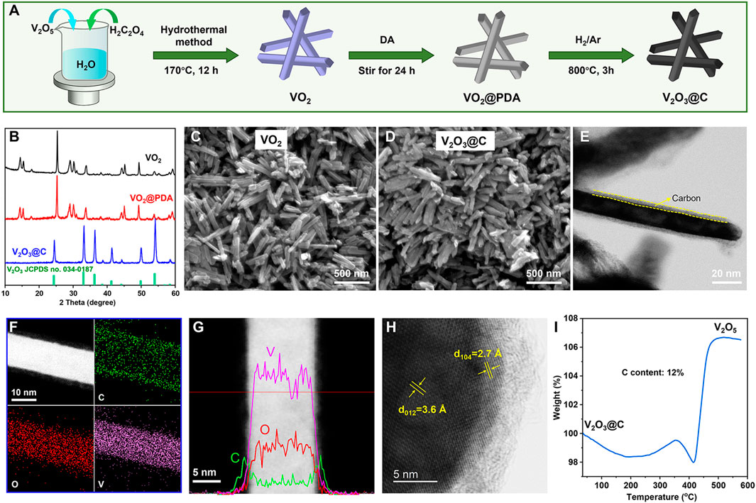
FIGURE 1. (A) Schematic illustration of the synthetic route for V2O3@C. (B) XRD patterns of as-prepared VO2, VO2@PDA, and V2O3@C. SEM images of (C) VO2 and (D) V2O3@C. (E) TEM, (F) STEM, and the corresponding elemental mapping of C, O, and V, (G) the linear elemental distribution, (H) HR-TEM image for V2O3@C nanorods. (I) TGA curves of V2O3@C nanorods under an air atmosphere.
3.2 Electrochemical performance of the V2O3@C cathode
Figure 2A shows the CVs of the V2O3@C cathode in the first 12 cycles at a scan rate of 0.5 mV s−1. There is an obvious anodic peak at ∼1.53 V versus Zn/Zn2+ in the first cycle and the first-cycle CV is quite different from the following CVs, signaling that an irreversible phase transformation has occurred during the first CV cycle. The phase transformation is not fully completed after the first cycle as the following CV curves still slowly change with cycling and are finally stabilized after the 11th cycle. The CV curve of the 12th cycle is similar to that of hydrated V2O5·nH2O, inferring an irreversible phase transformation during cycling from V2O3 to V2O5·nH2O. A similar phase transformation has also been proved by previous references (Yan et al., 2018; Zhu et al., 2021b; Zhu et al., 2021d). V2O3 is a reductant and it will be oxidized at a high potential in an aqueous solution. In contrast, V2O5·nH2O is a strong oxidant. Therefore, the phase transformation from V2O3 to V2O5·nH2O is reasonable at a high potential in an aqueous solution. In addition, the CV curves of the V2O3@C cathode in 2 M ZnSO4 are similar to those of the V2O3@C cathode in 2 M Zn(OTf)2, indicating that the irreversible phase transformation of V2O3 to V2O5·nH2O also occurs in 2 M Zn(OTf)2. To unveil the transformation, XRD and SEM were performed. The XRD results in Figure 2B show that the V2O3 structure is fully transformed into V2O5·nH2O with low crystallinity, while the SEM images in Figures 2C,D indicate an obvious change in the morphology from nanorods to ultrathin nanowires. During the oxidation of V2O3, V2O3 undergoes the destruction of the crystal structure and recrystallization of V2O5·nH2O. Thus, the vanadium should be redistributed and located on the surface of the electrodes. Therefore, it is reasonable to conclude that the increase in the capacity and shape changes of CV curves are due to the transformation of V2O3 to V2O5·nH2O. It is worth noting that even if a carbon shell is coated on the V2O3 surface, the V species is also transferred from the inside of the carbon shell to the outside during oxidation. The results indicate that the carbon shell is porous, and thus, permeable to the electrolyte solution. The porous structure of the carbon shell can be further confirmed by a much higher BET area and smaller pore size of V2O3@C (36 m2 g−1, 14 nm) compared to V2O3 (10 m2 g−1, 28 nm), as shown in Supplementary Figure S4.
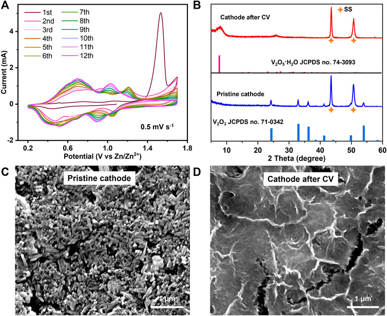
FIGURE 2. (A) CV curves of the V2O3@C cathode in 2 M ZnSO4. (B) XRD patterns and (C,D) SEM images of a pristine cathode and cathode after CV in Figure 2A for the V2O3@C cathode.
Figure 3 shows the electrochemical performance of the V2O3@C cathode in AZIBs. The discharge/charge curves in Figure 3A show that the first discharge capacity is only 45 mA h g−1 at 1 A g−1, while the first charge capacity is as high as 1,450 mA h g−1 with two plateaus at ∼1.4 and ∼1.5 V, respectively. The latter is a sign of the phase transformation from V2O3 to V2O5·nH2O when charging. The higher charge capacity than the theoretical capacity (715 mA h g−1) arises from the low Faraday efficiency of the oxidation reaction. After the oxidation at the first cycle, the discharge capacity of the second cycle is increased to 300 mA h g−1, while the charge capacity is decreased to 412 mA h g−1. Then the discharge capacity is slowly increased and stabilized at 336 mA h g−1, while the charge capacity is decreased slowly to 335 mA h g−1. The low Coulombic efficiencies in the initial cycles are because there are some side reactions during the electro-oxidization of V2O3 to V2O5·1.75H2O. It should be noted that the aforementioned capacity is based on the initial mass of V2O3. Suppose all V2O3 is fully transformed to V2O5·1.75H2O [the water content is obtained in the d-spacing of (001)], 1 g V2O3 would be transformed to 1.37 g V2O5·1.75H2O. Therefore, the capacity of 336 mA h g−1 based on the V2O3 mass corresponds to 245 mA h g−1 based on the V2O5·1.75H2O mass. The results are consistent with the CV results (Figure 2A) that V2O3 undergoes fast and incomplete oxidation in the first cycle, followed by slow and complete oxidation. Figure 3B shows that the capacity retention rate is 83% after 200 cycles at 1 A g−1 after full oxidation of V2O3 to V2O5·nH2O in the V2O3@C cathode, demonstrating excellent long-term cycle stability. It should be noted that the V2O3@C cathode shows much better stability than the V2O3 cathode, as shown in Figure 3B. Additionally, Figures 3C,D indicate that the rate capability and long-term stability at 10 A g−1 of the V2O3@C cathode are also superior to that of the V2O3 cathode. Thus, the carbon shell should play a vital role in long-term stability. It should be noted that the specific capacity of the V2O3@C cathode is based on the total mass of V2O3 and C, leading to a lower capacity of the V2O3@C cathode than that of the V2O3 cathode. Although the capacities of the first 25 cycles for the V2O3@C cathode are a little lower than those for the V2O3 cathode at 1 A g−1, the former shows a much higher capacity than the latter after 25 cycles (see Figure 3B). Furthermore, Figure 3D shows that the V2O3@C cathode delivers a much higher capacity (200 mA h g−1) than the V2O3 cathode (150 mA h g−1) at a high current density of 20 A g−1. Figure 3C also shows 94 and 93% capacity recovery after the current density resumes to 2 and 1 A g−1 from 20 A g−1 excursion. At 10 A g−1, 65% of the highest capacity (205 mA h g−1) is retained after 1,000 cycles, as shown in Figure 3D. These results suggest that the V2O3@C cathode possesses good cycling stability benefiting from the favorable role of the carbon shell. At 1 A g−1 and 10 A g−1, it takes fewer cycles (or time) to achieve the highest discharge capacity for the V2O3@C cathode compared to the V2O3 cathode (see Figures 3B–D), indicating that the carbon shell could promote the oxidation of V2O3. Intrinsically, V2O3 has poor Zn2+-storage ability, far worse than V2O5·nH2O. Thus, AZIBs will deliver the highest discharge capacity when V2O3 is fully transformed to hydrated V2O5·nH2O. Therefore, it is reasonable to say that carbon promotes the oxidation of V2O3 to V2O5·nH2O benefiting from the high conductivity and small particle size of V2O3 in V2O3@C.
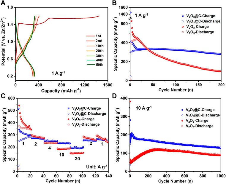
FIGURE 3. (A) Discharge/charge curves represent cycles at 1 A g−1 for the V2O3@C cathode in aqueous ZnSO4 solution. (B) cycling performance at a low rate (1 A g−1), (C) rate performance, and (D) cycling performance at a high rate (10 A g−1) for V2O3 and V2O3@C cathodes in aqueous ZnSO4 solution.
Overall, the carbon shell in V2O3@C has the following roles. First, the carbon shell prevents the growth of V2O3 during preparation at high temperatures (800°C) as shown in Figures 1D and Supplementary Figure S2. Second, the carbon shell should decrease the dissolution of V2O3 and increases the electronic conductivity of V2O3 arising from the outer layer protection. Third, the carbon shell carbon promotes the oxidation of V2O3 to V2O5·nH2O.
3.3 The ex situ characterization and reaction mechanism
To further confirm the transformation of V2O3 to V2O5·nH2O and the Zn2+-storage mechanism of the in situ generated V2O5·nH2O cathode, ex situ XRD and SEM were performed during cycling. Figure 4A shows that a weak peak corresponding to Zn4SO4(OH)6·3H2O (ZSH) appears when discharged to 0.2 V (1D-0.2 V); upon charging to 1.6 V (1C-1.6 V), the peak corresponding to ZSH completely disappeared. According to previous studies, the root cause of ZSH formation is H+ intercalation (Huang et al., 2018; Zhu et al., 2021d). Additionally, the XRD peaks (Figure 4A) of V2O3 after the first cycle in the aqueous ZnSO4 (2 M) electrolyte vanished, probably due to the phase transformation. After the complete oxidation of V2O3 to V2O5·nH2O, the XRD peak for ZSH also appears reversible and vanishes during cycling, indicating the reversible H+ intercalation/de-intercalation into/from V2O5·nH2O. The SEM images in Figures 4B–E show that ZSH nanoflakes appear on the surface of V2O3 and V2O5·nH2O electrodes upon discharge and disappear after charge.
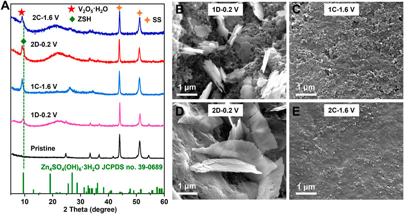
FIGURE 4. (A) XRD patterns of the V2O3@C cathode at pristine state (Pristine), discharged state in the first or second cycle (1D-0.2 V; 2D-0.2 V), charged state in the first cycle or second cycle (1C-1.6V; 2C-1.6 V) in aqueous ZnSO4 solution at 0.5 A g−1. SEM images of the V2O3@C cathode at (B) discharged state at the first cycle (1D-0.2 V), (C) charged state in the first cycle (1C-1.6 V), (D) discharged state in the second cycle (2D-0.2 V), and (E) charged state in the second cycle (2C-1.6 V), in aqueous ZnSO4 solution at 0.5 A g−1.
The aforementioned results are also confirmed by XPS in Figure 5, where a sharper increase in Zn 2p intensity is observed on the fully discharged cathode for V2O3 (1D-0.2 V) and V2O5·nH2O (2D-0.2 V) than those on the pristine and charged states (1C-1.6 V and 2C-1.6 V), suggesting that a possible Zn-containing compound (ZSH) is formed on the surface of the electrode. It is to be noted that XPS is a surface technique capable of penetrating ∼5 nm depth. Therefore, the much lower V signals on the XPS spectra of the discharged products (and 2D-0.2 V) compared to the pristine and the charged electrodes (1C-1.6 V and 2C-1.6 V) could be due to the interference of surface ZSH. The extremely low V signals of the discharged V2O5·nH2O electrode (2D-0.2 V) infer that there is a lot of surface ZSH covered on the electrode. Therefore, ex situ SEM, XRD, and XPS have convincingly demonstrated that H+ indeed takes part in the electrochemical process during cycling.
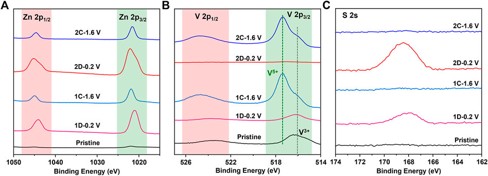
FIGURE 5. XPS spectra of (A) Zn 2p, (B) V 2p, and (C) S 2s for the V2O3@C cathode at pristine state (Pristine), discharged state in the first or second cycle (1D-0.2 V; 2D-0.2 V), and charged state in the first cycle (1C-1.6V; 2C-1.6 V) in aqueous ZnSO4 solution at 0.5 A g−1.
Additionally, the electrochemical performance of the oxidized electrode (2C-1.6 V) in the aqueous ZnSO4 (2 M) solution and organic Zn(CF3SO3)2 (1 M) solution (solvent: acetonitrile) was compared to demonstrate the Zn2+-intercalation. Figure 6 shows that the capacity in organic Zn(OTf)2 solution is only ∼110 mA h g−1 at a current of 0.5 A g−1, much lower than that (∼360 mA h g−1) in aqueous ZnSO4 solution. As there is no H+ in the organic Zn(OTf)2 solution, only Zn2+ can be involved during cycling. The capacity in organic Zn(OTf)2 solution should be attributed to Zn2+-intercalation/deintercalation. The higher capacity in aqueous ZnSO4 solution than that in organic Zn(OTf)2 solution also infers the involvement of H+ in aqueous ZnSO4 solution. Overall, apart from the involvement of Zn2+, H+ also takes part in the electrochemical process during cycling.
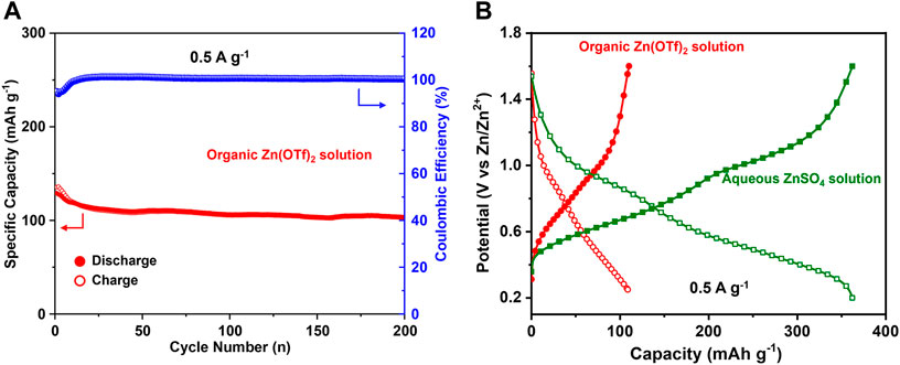
FIGURE 6. (A) Cycling performance of the V2O3@C cathode in organic Zn(OTf)2 solution at 0.5 A g−1. (B) Discharge/charge curves in the 50th cycle for the V2O3@C cathode in organic Zn(OTf)2 solution and aqueous ZnSO4 solution at 0.5 A g−1.
To further understand the intercalation behavior of Zn2+/H+, CV measurements at different scan rates from 0.2 to 1 mV s−1 were performed on hydrated V2O5·nH2O obtained by the electrochemical oxidation of V2O3 (Figure 7A). There are two pairs of redox peaks corresponding to the changes in the oxidation state of V5+/V4+ (peaks 2 and 3) and V4+/V3+ (peaks 1 and 4). Generally, the peak current (i) of CVs can be related to the scan rate (ʋ) by the following empirical power-law relationship (Augustyn et al., 2014):
where k1, k2, a, and b are variable parameters with b = 0.5 for a diffusion-controlled charge-transfer process and 1.0 for a surface-controlled capacitive process. Figure 7B shows that b-values obtained from the slopes of log(i) versus log(ʋ) for the four peaks are 0.76, 0.88, 0.85, and 0.82. Therefore, the intercalation behavior of Zn2+/H+ in hydrated V2O5·nH2O obtained by the electrochemical oxidation of V2O3 is controlled by ionic diffusion and surface capacitance synchronously.
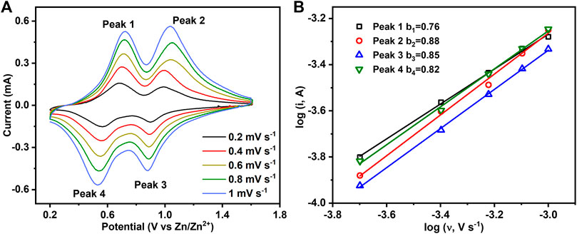
FIGURE 7. (A) CV curves of hydrated V2O5·nH2O obtained by the electrochemical oxidation of V2O3 at different scan rates. (B) Plots of log(i) vs. log(v) for the four redox peaks in Figure 7A.
4 Conclusion
In this study, carbon shell-coated V2O3 nanorods were successfully prepared and showed good electrochemical performance in ZIBs. Strong pieces of evidence were provided to demonstrate that V2O3 would be oxidized to V2O5·nH2O when charged, while the carbon shell could promote the oxidation of the V2O3 core and have a favorable role in stability. Benefiting from the carbon shell, V2O3@C exhibits a much improved rate-capability and cycling stability compared to pure V2O3. The discharge capacity of V2O3 was only ∼45 mA h g−1 at 1 A g−1, while the capacity was increased to 350 mA h g−1 after oxidizing V2O3 to V2O5·nH2O. When the current is increased from 1 to 20 A g−1, the capacity retention for the V2O3@C electrode is 69%, much higher than that for V2O3 electrode (44%). Additionally, the long-term stabilities at the currents of 1 A g−1 and 10 A g−1 for V2O3@C are much better than those for the V2O3 electrode. Overall, coating the carbon shell on the active materials provides a way to enhance the rate-capability and long-term cycling stability, and the strategy of introducing the carbon shell on the surface of V2O3 nanorods can be extended to other materials.
Data availability statement
The original contributions presented in the study are included in the article/Supplementary Material; further inquiries can be directed to the corresponding author.
Author contributions
ZH: data curation, formal analysis, and writing—original draft. WJ: data curation and formal analysis. KZ: data curation, formal analysis, writing—review and editing, and funding acquisition.
Funding
This work is supported by the Youth Innovation Fund of Dalian Institute of Chemical Physics (DICP I202126) and the Strategic Priority Research Program of the Chinese Academy of Sciences (XDB17020400).
Acknowledgments
We would like to thank the State Key laboratory of Catalysis and Institute Center for shared Technologies and facilities of DICP for the characterizations.
Conflict of interest
The authors declare that the research was conducted in the absence of any commercial or financial relationships that could be construed as a potential conflict of interest.
Publisher’s note
All claims expressed in this article are solely those of the authors and do not necessarily represent those of their affiliated organizations, or those of the publisher, the editors, and the reviewers. Any product that may be evaluated in this article, or claim that may be made by its manufacturer, is not guaranteed or endorsed by the publisher.
Supplementary material
The Supplementary Material for this article can be found online at: https://www.frontiersin.org/articles/10.3389/fchem.2022.956610/full#supplementary-material
Supplementary Figure S1 | XRD patterns of as-prepared VO2,VO2@PDA, and standard VO2.
Supplementary Figure S2 | XRD patterns of VO2 and V2O3 prepared without using PDA.
Supplementary Figure S3 | CV curves of the V2O3@C cathode in 2 M Zn(OTf)2.
Supplementary Figure S4 | Nitrogen adsorption–desorption isotherm curves of V2O3 and V2O3@C powders. Inset shows the BET area and average pore size.
References
Augustyn, V., Simon, P., and Dunn, B. (2014). Pseudocapacitive oxide materials for high-rate electrochemical energy storage. Energy Environ. Sci. 7, 1597–1614. doi:10.1039/C3EE44164D
Bin, D., Wang, F., Tamirat, A. G., Suo, L., Wang, Y., Wang, C., et al. (2018). Progress in aqueous rechargeable sodium-ion batteries. Adv. Energy Mat. 8 (17), 1703008. doi:10.1002/aenm.201703008
Blanc, L. E., Kundu, D., and Nazar, L. F. (2020). Scientific challenges for the implementation of Zn-ion batteries. Joule 4 (4), 771–799. doi:10.1016/j.joule.2020.03.002
Chao, D., Zhou, W., Xie, F., Ye, C., Li, H., Jaroniec, M., et al. (2020). Roadmap for advanced aqueous batteries: from design of materials to applications. Sci. Adv. 6, eaba4098. doi:10.1126/sciadv.aba4098
Chen, H., Rong, Y., Yang, Z., Deng, L., and Wu, J. (2021). V2O3@Amorphous carbon as a cathode of zinc ion batteries with high stability and long cycling life. Ind. Eng. Chem. Res. 60 (4), 1517–1525. doi:10.1021/acs.iecr.0c05534
Ding, Y., Peng, Y., Chen, S., Zhang, X., Li, Z., Zhu, L., et al. (2019). Hierarchical porous metallic V2O3@C for advanced aqueous zinc-ion batteries. ACS Appl. Mat. Interfaces 11 (47), 44109–44117. doi:10.1021/acsami.9b13729
Fang, G., Zhou, J., Pan, A., and Liang, S. (2018). Recent advances in aqueous zinc-ion batteries. ACS Energy Lett. 3 (10), 2480–2501. doi:10.1021/acsenergylett.8b01426
Hu, P., Yan, M., Zhu, T., Wang, X., Wei, X., Li, J., et al. (2017). Zn/V2O5 aqueous hybrid-ion battery with high voltage platform and long cycle life. ACS Appl. Mat. Interfaces 9 (49), 42717–42722. doi:10.1021/acsami.7b13110
Huang, J., Wang, Z., Hou, M., Dong, X., Liu, Y., Wang, Y., et al. (2018). Polyaniline-intercalated manganese dioxide nanolayers as a high-performance cathode material for an aqueous zinc-ion battery. Nat. Commun. 9 (1), 2906. doi:10.1038/s41467-018-04949-4
Jia, X., Liu, C., Neale, Z. G., Yang, J., and Cao, G. (2020). Active materials for aqueous zinc ion batteries: synthesis, crystal structure, morphology, and electrochemistry. Chem. Rev. 120 (15), 7795–7866. doi:10.1021/acs.chemrev.9b00628
Lee, H., Dellatore, M. S., Miller, M. W., and Messersmith, B. P. (2007). Mussel-inspired surface Chemistry for multifunctional coatings. Science 318, 426–430. doi:10.1126/science.1147241
Li, H.-Y., Jiao, K., Wang, L., Wei, C., Li, X., and Xie, B. (2014). Micelle anchored in situ synthesis of V2O3 nanoflakes@C composites for supercapacitors. J. Mat. Chem. A 2 (44), 18806–18815. doi:10.1039/c4ta04062g
Li, R., Zhang, H., Zheng, Q., and Li, X. (2020). Porous V2O5 yolk-shell microspheres for zinc ion battery cathode: activation responsible for enhanced capacity and rate performance. J. Mat. Chem. A 8, 5186–5193. doi:10.1039/c9ta11750d
Li, C., Zheng, C., Jiang, H., Bai, S., and Jia, J. (2021). Synergistic effect of structural stability and oxygen vacancies enabling long-life aqueous zinc-ion battery. Mat. Lett. 302, 130373. doi:10.1016/j.matlet.2021.130373
Liang, H., Cao, Z., Ming, F., Zhang, W., Anjum, D. H., Cui, Y., et al. (2019). Aqueous zinc-ion storage in MoS2 by tuning the intercalation energy. Nano Lett. 19 (5), 3199–3206. doi:10.1021/acs.nanolett.9b00697
Liu, Y., Ai, K., and Lu, L. (2014). Polydopamine and its derivative materials: synthesis and promising applications in energy, environmental, and biomedical fields. Chem. Rev. 114 (9), 5057–5115. doi:10.1021/cr400407a
Luo, H., Wang, B., Wang, F., Yang, J., Wu, F., Ning, Y., et al. (2020). Anodic oxidation strategy toward structure-optimized V2O3 cathode via electrolyte regulation for Zn-ion storage. ACS Nano 14 (6), 7328–7337. doi:10.1021/acsnano.0c02658
Ming, F., Liang, H., Lei, Y., Kandambeth, S., Eddaoudi, M., and Alshareef, H. N. (2018). Layered MgxV2O5·nH2O as cathode material for high-performance aqueous zinc ion batteries. ACS Energy Lett. 3 (10), 2602–2609. doi:10.1021/acsenergylett.8b01423
Ming, J., Guo, J., Xia, C., Wang, W., and Alshareef, H. N. (2019). Zinc-ion batteries: materials, mechanisms, and applications. Mat. Sci. Eng. R. Rep. 135, 58–84. doi:10.1016/j.mser.2018.10.002
Pan, A., Wu, H. B., Yu, L., Zhu, T., and Lou, X. W. (2012). Synthesis of hierarchical three-dimensional vanadium oxide microstructures as high-capacity cathode materials for lithium-ion batteries. ACS Appl. Mat. Interfaces 4 (8), 3874–3879. doi:10.1021/am3012593
Posada-Pérez, S., Rignanese, G.-M., and Hautier, G. (2021). Influence of stacking on H+ intercalation in layered ACoO2 (A = Li, Na) cathode materials and implications for aqueous Li-ion batteries: a first-principles investigation. Chem. Mat. 33 (17), 6942–6954. doi:10.1021/acs.chemmater.1c01887
Ren, H.-Z., Zhang, J., Wang, B., Luo, H., Jin, F., Zhang, T.-R., et al. (2022). A V2O3@N–C cathode material for aqueous zinc-ion batteries with boosted zinc-ion storage performance. Rare Met. 41, 1605–1615. doi:10.1007/s12598-021-01892-0
Song, M., Tan, H., Chao, D., and Fan, H. J. (2018). Recent advances in Zn-ion batteries. Adv. Funct. Mat. 28 (41), 1802564. doi:10.1002/adfm.201802564
Tang, B., Shan, L., Liang, S., and Zhou, J. (2019). Issues and opportunities facing aqueous zinc-ion batteries. Energy Environ. Sci. 12 (11), 3288–3304. doi:10.1039/c9ee02526j
Tarascon, J. M., and Armand, M. (2001). Issues and challenges facing rechargeable Lithium batteries. Nature 414, 359–367. doi:10.1038/35104644
Wan, F., and Niu, Z. (2019). Design strategies for vanadium-based aqueous zinc-ion batteries. Angew. Chem. Int. Ed. 58 (46), 16358–16367. doi:10.1002/anie.201903941
Wan, F., Zhu, J., Huang, S., and Niu, Z. (2019). High-voltage electrolytes for aqueous energy storage devices. Batter. Supercaps 3 (4), 323–330. doi:10.1002/batt.201900229
Wang, F., Blanc, L. E., Li, Q., Faraone, A., Ji, X., Chen-Mayer, H. H., et al. (2021). Quantifying and suppressing proton intercalation to enable high-voltage Zn-ion batteries. Adv. Energy Mat. 11 (41), 2102016. doi:10.1002/aenm.202102016
Wang, X., Zhang, Z., Huang, M., Feng, J., Xiong, S., and Xi, B. (2021). In situ electrochemically activated vanadium oxide cathode for advanced aqueous Zn-ion batteries. Nano Lett. 22 (1), 119–127. doi:10.1021/acs.nanolett.1c03409
Yan, M., He, P., Chen, Y., Wang, S., Wei, Q., Zhao, K., et al. (2018). Water-lubricated intercalation in V2O5·nH2O for high-capacity and high-rate aqueous rechargeable zinc batteries. Adv. Mat. 30 (1), 1703725. doi:10.1002/adma.201703725
Yang, Z., Zhang, J., Kintner-Meyer, M. C., Lu, X., Choi, D., Lemmon, J. P., et al. (2011). Electrochemical energy storage for green grid. Chem. Rev. 111 (5), 3577–3613. doi:10.1021/cr100290v
Zhang, N., Dong, Y., Jia, M., Bian, X., Wang, Y., Qiu, M., et al. (2018). Rechargeable aqueous Zn–V2O5 battery with high energy density and long cycle life. ACS Energy Lett. 3 (6), 1366–1372. doi:10.1021/acsenergylett.8b00565
Zhang, N., Chen, X., Yu, M., Niu, Z., Cheng, F., and Chen, J. (2020a). Materials chemistry for rechargeable zinc-ion batteries. Chem. Soc. Rev. 49, 4203–4219. doi:10.1039/c9cs00349e
Zhang, S., Tan, H., Rui, X., and Yu, Y. (2020b). Vanadium-based materials: next generation electrodes powering the battery revolution? Acc. Chem. Res. 53 (8), 1660–1671. doi:10.1021/acs.accounts.0c00362
Zhou, J., Shan, L., Wu, Z., Guo, X., Fang, G., and Liang, S. (2018). Investigation of V2O5 as a low-cost rechargeable aqueous zinc ion battery cathode. Chem. Commun. 54 (35), 4457–4460. doi:10.1039/c8cc02250j
Zhu, K., Wu, T., and Huang, K. (2019a). A high capacity bilayer cathode for aqueous Zn-ion batteries. ACS Nano 13 (12), 14447–14458. doi:10.1021/acsnano.9b08039
Zhu, K., Wu, T., and Huang, K. (2019b). NaCa0.6V6O16·3H2O as an ultra-stable cathode for Zn-ion batteries: the roles of pre-inserted dual-cations and structural water in V3O8 layer. Adv. Energy Mat. 9 (38), 1901968. doi:10.1002/aenm.201901968
Zhu, K., Wu, T., Sun, S., van den Bergh, W., Stefik, M., and Huang, K. (2020a). Synergistic H+/Zn2+ dual ion insertion mechanism in high-capacity and ultra-stable hydrated VO2 cathode for aqueous Zn-ion batteries. Energy Storage Mat. 29, 60–70. doi:10.1016/j.ensm.2020.03.030
Zhu, K., Wu, T., Sun, S., Wen, Y., and Huang, K. (2020b). Electrode materials for practical rechargeable aqueous Zn-ion batteries: challenges and opportunities. ChemElectroChem 7, 2714–2734. doi:10.1002/celc.202000472
Zhu, K., Wei, S., Shou, H., Shen, F., Chen, S., Zhang, P., et al. (2021a). Defect engineering on V2O3 cathode for long-cycling aqueous zinc metal batteries. Nat. Commun. 12 (1), 6878. doi:10.1038/s41467-021-27203-w
Zhu, K., Wu, T., and Huang, K. (2021b). A high-voltage activated high-erformance cathode for aqueous Zn-ion batteries. Energy Storage Mat. 38, 473–481. doi:10.1016/j.ensm.2021.03.031
Zhu, K., Wu, T., and Huang, K. (2021c). Understanding the dissolution and phase transformation mechanisms in aqueous Zn/α-V2O5 batteries. Chem. Mat. 33 (11), 4089–4098. doi:10.1021/acs.chemmater.1c00715
Keywords: carbon shell, V2O3 nanorods, phase transformation, V2O5·nH2O, aqueous Zn-ion batteries
Citation: Hao Z, Jiang W and Zhu K (2022) Carbon-encapsulated V2O3 nanorods for high-performance aqueous Zn-ion batteries. Front. Chem. 10:956610. doi: 10.3389/fchem.2022.956610
Received: 30 May 2022; Accepted: 25 July 2022;
Published: 02 September 2022.
Edited by:
Yunjun Ruan, Guizhou University, ChinaReviewed by:
Sergio Posada Pérez, Universitat de Girona, SpainHanfeng Liang, Xiamen University, China
Copyright © 2022 Hao, Jiang and Zhu. This is an open-access article distributed under the terms of the Creative Commons Attribution License (CC BY). The use, distribution or reproduction in other forums is permitted, provided the original author(s) and the copyright owner(s) are credited and that the original publication in this journal is cited, in accordance with accepted academic practice. No use, distribution or reproduction is permitted which does not comply with these terms.
*Correspondence: Kaiyue Zhu, emt5MjE4QGRpY3AuYWMuY24=