 Zhongmin Hou
 Xiaomin Wang1*
 Yiyong Wang
- 1Liaoning Key Laboratory of Chemical Additive Synthesis and Separation, School of Materials Science and Engineering, Yingkou Institute of Technology, Liaoning Yingkou, China
- 2School of Materials and Metallurgy, University of Science and Technology Liaoning, Liaoning Anshan, China
Indium is a crucial material and is widely used in high-tech industries, and electrodeposition is an efficient method to recover rare metal resources. In this work, the electrochemical behavior of In3+ was investigated by using different electrochemical methods in electrolytes containing sodium and indium sulfate. Cyclic voltammetry (CV), chronoamperometry (CA), and alternating current impedance (EIS) techniques were used to investigate the reduction reaction of In3+ and the electrocrystallization mechanism of indium in the indium sulfate system. The cyclic voltammetry results showed that the electrodeposition process is irreversible. The average charge transfer coefficient a of In3+ was calculated to be 0.116 from the relationship between the cathodic peak potential and the half-peak potential, and the H+ discharge occurred at a higher negative potential of In3+. The nucleation mechanism of indium electrodeposition was analyzed by chronoamperometry. The mechanism of indium at potential steps of −0.3 to −0.6 V was close to diffusion-controlled instantaneous nucleation with a diffusion coefficient of 7.31 × 10⁻⁹ cm2 s−1. The EIS results demonstrated that the reduction process of In3+ is subject to a diffusion-controlled step when pH = 2.5 and the applied potential was −0.5 V. SEM and XRD techniques indicated that the cathodic products deposited on the titanium electrode have excellent cleanliness and purity.
Introduction
Indium is a bright and silvery-white rare metal with low melting point, high flexibility, high boiling point, and a face-centered tetragonal crystal structure. At room temperature, indium is not oxidized by air and its chemical properties are relatively stable (Katiyar and Randhawa, 2020). With the increasing demand for indium in the high-tech field, the purity of indium has become more demanding. High-purity indium is mainly used in semiconductors, fluorescent materials, ITO films, and photovoltaic solar cells (Xu et al., 2021; Luo et al., 2022). In addition, high purity indium has become the top classification of critical materials due to its wide application, such as liquid crystal displays and light-emitting diodes (Fontana et al., 2015; Rakhymbay et al., 2016).
In order to achieve a better supply of indium in globalization, indium is mainly extracted from zinc ore, sublimate, and lead-containing materials, and the recovery rate is 50–60% (Cheng et al., 2021; Xu et al., 2021). The indium resources of China rank first in the world. In 2006, China’s indium output accounted for more than 60% of the world but it was highly dependent on exports and the supply of indium could not meet the demand. At present, the critical challenge in dealing with the new market is to seek the raw material supply of indium (Kang et al., 2011).
In the extraction and purification of indium, a combination of chemical cleaning and physical purification is mainly adopted, including the electrolytic refining method, float zone smelting method, vacuum distillation method, and metal–organic compound method (Bardi et al., 2009; Liu et al., 2021). Based on hydrometallurgy, electrolytic refining of the aqueous solution is paid more attention because of its advantages of the simple operation process and low cost of equipment. Yu et al. (2013) studied the effects of acidity, current density, and other parameters on electrolytic purification and controlled the optimal electrolytic conditions, which are more conducive to the purification of indium. Liu (2010) used glycerol potassium iodide for the prior removal of Cd and Tl and investigated the effect of acidity on the product purity and current efficiency in indium electrolytic refining; the optimal pH of the electrolytic process was determined to be 2–3.
The electrical crystallization of metals mainly consists of the atomic generation of crystalline nuclei after the ions enter the electrolyte and discharge at the electrode surface. The overpotential has a specific influence on the rate of nuclei formation (Zhao et al., 2014; Shelke et al., 2020; Liu et al., 2021). It is possible to refine crystallization only if the rate of the crystal nucleus is greater than the crystal growth rate. The complexity of the electron crystallization process is related to the inhomogeneity of the crystal surface and the generation of new phases (Eliaz and Sridhar, 2008).
Indium deposition includes chemical deposition and electrodeposition. Electrodeposition is an excellent preparation method and involves low cost, high speed, and extensive film (Zhang et al., 2001; Avchukir et al., 2018). In the early stages of metal deposition, metal ions were transferred by hemispherical diffusion and three-dimensional diffusion. The process of indium deposition is affected by the hydrogen overpotential. Using electrochemical methods, Li et al. (2006) demonstrated the mechanism of the cathodic reaction in indium sulfate type plating and found that the cathodic reduction process involves prechemical and irreversible electrochemical reactions. Ciro et al. (2020) examined the indium electrode process using different metals as cathodes and concluded that Ni and SS are the most suitable cathode carriers. Rakhymbay et al. (2016) studied the deposition mechanism of indium by the electrochemical method and calculated the diffusion coefficient and diffusion activation energy. Pettit et al. (2002) researched the kinetics of indium deposition on molybdenum substrates and concluded that SHG and FFT-EIS can be used to investigate electrodeposition surface modification processes. Luo et al. (2022) analyzed the removal mechanism of lead and the behavior of selenium in the purification process by controlling the potential oxidation and vacuum distillation, indicating that lead impurities can be removed by combining these two methods effectively.
In this work, the electrodeposition process of indium in an indium sulfate system was studied by cyclic voltammetry, chronoamperometry, and the AC impedance method. The function and mechanism of cathode recovery of indium were determined. The deposition layer was scraped off, and the morphology was observed by scanning electron microscopy. The crystallinity of indium in the range of 10°–90° was evaluated using an x-ray energy dispersive spectrometer. The study of the electrochemical behavior of indium ions can lay a foundation for the preparation of high-purity indium and the electrochemical regulation of impurities, which can provide theoretical guidance for the electrolytic refining process of crude indium.
Materials and Methods
Indium sulfate used in this experiment was provided by Shanghai McLin Biochemical Technology Co., Ltd. The purity was 99.99%, which met the ideal requirements. Anhydrous sodium sulfate was provided by Liaoning Quanrui Reagent Co., Ltd. with the purity of AR. In electrochemistry experiments, indium sulfate was not added in the control experiment. The electrolyte in one group contained only sodium sulfate at a concentration of 0.07 mol/L. The other group of experimental electrolytes contained indium sulfate and sodium sulfate at concentrations of 0.03 mol/L and 0.07 mol/L, respectively. A three-electrode system was used to study the reaction mechanism of the electrode. The effective area of the titanium plate as a working electrode was 9.5 cm2, and the effective area of the current timing test was 8.74 cm2. The working electrode was polished, cleaned, and soaked in anhydrous ethanol prior to use. The surface of the platinum electrode was carefully polished with 1000 sandpaper, which removed the oxide film and then wiped with alcohol cotton. Finally, it was ultrasonically cleaned with distilled water and anhydrous ethanol and then placed in anhydrous ethanol for 20 min before use. In the electrodeposition experiment, coarse indium was used as an anode and a high-purity titanium plate was used as a cathode (Lobaccaro et al., 2014; Dell'Era et al., 2020). The electrolyte was an indium sulfate electrolytic system, and NaCl was added to enhance its conductivity (Walsh and Gabe, 1981; Liu et al., 2021).
The experimental mechanism is as follows:
Anode:
Cathode:
Results and Discussion
Cyclic Voltammetry Analysis
The electrode reaction mechanism on the cathode surface with or without In3+ as an electrolyte was determined by cyclic voltammetry. The test temperature was 298 K. The potential was set from 1 V to −1.8 V with pH = 2.5 in the indium sulfate system. The test results are shown in Figure 1.
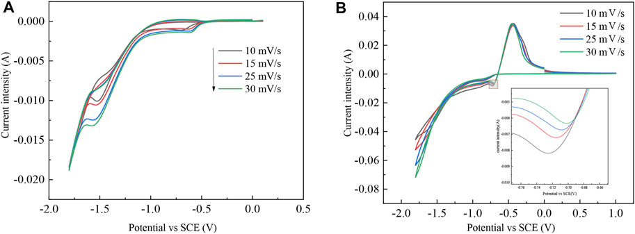
FIGURE 1. CV curves containing different electrolytes: (A) 0.07 mol/L Na2SO4 and (B) 0.03 mol/L In2(SO4)3 and 0.07 mol/L Na2SO4.
During the electrolysis of indium dissolved in the anode, the indium in the crude indium enters the electrolyte in an ion form. The redox process of In3+ is determined from the preliminary CV curves. In the electrolyte containing sodium sulfate, the hydrogen discharge potential in the Ti metal carrier is approximately −1.06 V, which indicates that the H+ discharge occurs only at a higher negative potential of the indium discharge and also verifies that H+ has a large overpotential for indium during the electrolytic refining process. The reduction of In3+ can be achieved on a titanium plate. There is an oxidation peak and a reduction peak on the curve, where it can be assumed that indium in crude indium enters the electrolyte as an ion and is oxidized to In3+. Under the action of electric field forces, In3+ migrates from the anodic region to the cathodic area, where it is reduced to In by getting three electrons at the cathode. Therefore, indium is diminished by an irreversible reaction of three electrons in one step, with a reduction potential between −0.65 V and −0.72 V and an oxidation potential between −0.42 V and −0.45 V (Rakhymbay et al., 2016; Liu et al., 2021).
The cross potential shows nucleation of In, which lays a foundation for further study of the nucleation mechanism. As shown in the inset of Figure 1B, the reduction peak shifts positively as the sweep speed increases.
To further prove the number of electrons transferred during the reduction of In3+ on the titanium plate, the relevant data were calculated and tabulated at any four points on the right-hand side of the cyclic voltammetric curve, using 30 mV/s as an example. This is shown in Table 1.
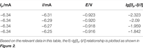
TABLE 1. Calculated data related to any four points in the cyclic voltammetric curve (30 mV/s).
Figure 2 shows that the E-lg[(Ip-I)/I] curve shows a good linear relationship with a fitted straight line slope K = 0.0144. According to the electron transfer number equation (Li et al., 2019), the number of electrons transferred during In3+ reduction can be calculated as follows:
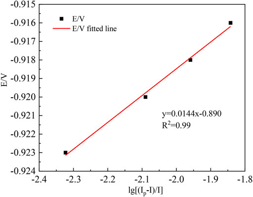
FIGURE 2. Graph of the E–lg [(Ip-I)/I] relationship (30 mV/s).
The slope
In order to study further the reversibility and charge transfer coefficient of the reaction of indium in crude indium on the titanium electrode, the test data in Figure 1B are drawn as shown in Table 2.

TABLE 2. Parameters corresponding to cyclic voltammetry curve of In3+ on Ti electrode at 298 K.
According to the data in Table 2, the reduction peak potential Ep and the logarithmic of the scanning speed ln v are plotted, as shown in Figure 3. As shown in Figure 3, the potential (Ep) linearly relates well the natural logarithm of the scan rate and further proves that the reduction process of In3+ at the Ti electrode is irreversible. Its peak potential Epc and half-peak potential Ep/2 satisfy the following equation (Xiao et al., 2017):
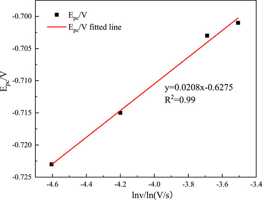
FIGURE 3. Relationship between Epc and lnv.
where Epc is the cathodic peak potential (V); Ep/2 is the half-peak potential (V); α is the charge transfer coefficient; n is the number of electrons transferred; F is the Faraday constant (C mol−1), R is the gas constant (J (mol K)−1); and T is the absolute temperature(K). Substituting the relative data into Equation 8, the average value of the charge transfer coefficient can be calculated to be 0.116.
The square root of the scanning speed v1/2 versus the reduction peak current Ipc is shown in Figure 4. The controlling steps of the electrochemical reaction of metal ions in an electrolyte solution can be determined assuming that a wonderful proportion relationship is found after fitting. In that case, the diffusion coefficient of In3+ in the system can be calculated according to the Berzins–Delahay equation (Kang et al., 2020; Li et al., 2020).
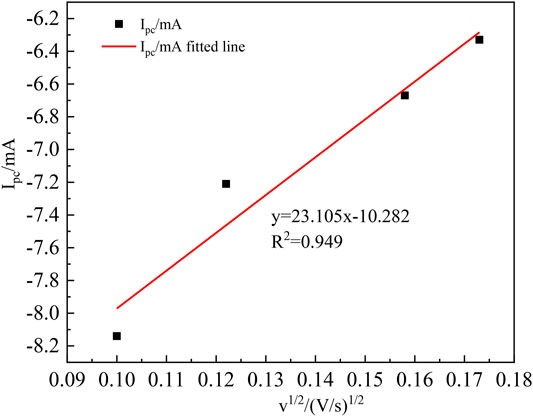
FIGURE 4. v1/2 relationship with the peak current Ipc.
Figure 4 shows that Ipc and v1/2 have an excellent linear relationship, indicating that the electrochemical reduction process of In3+ is controlled by the diffusion control step, and the diffusion coefficient of In3+ can be found from the Berzins–Delahay equation (Li et al., 2019; Rajska et al., 2021):
where Ipc is the cathodic peak current; n is the number of electrons transferred; F is the Faraday constant (C mol−1), R is the gas constant (J (mol K)−1); Tis the absolute temperature (K); α is the charge transfer coefficient; S is the working electrode area (cm2); C0 is the In3+ concentration (mol L−1); v is the sweep velocity (mV s−1);
According to Eq. (9), when Ip/v1/2 = 23.105 mA s mV−1, n = 3, F = 96,485 C mol−1, R = 8.314 J (mol K)−1, T = 298 K, α = 0.116, S = 9.5 cm2, C0 = 0.06 mol cm−3, it can be computed that
Chronoamperometric Analysis
The nucleation process in acidic aqueous solutions of indium sulfate containing sodium sulfate was studied by chronoamperometry. The temperature was 298 K and the potential ranged from −0.3 V to −0.6 V. The experimental results are shown in Figure 5. The relationship between current intensity and the negative square root of the transition time is shown in Figure 6.
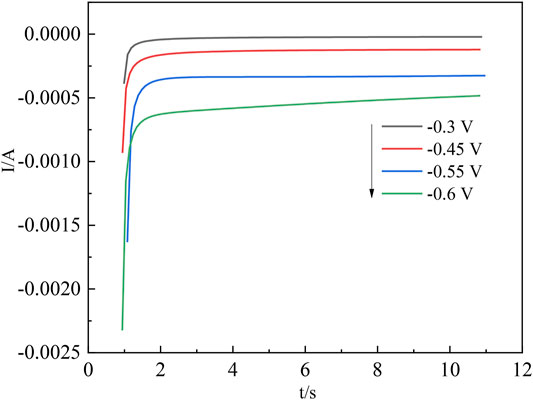
FIGURE 5. Chronoamperometric current curves for In3+ at different potentials.
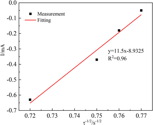
FIGURE 6. Relationship between the current intensity I(t) and the negative square root of the transition time (τ−1/2).
The diffusion coefficient of In3+ was calculated from the Sand equation (Kang et al., 2020) as follows:
The transition time τ−1/2 in the timing current shows a good linear relationship with the current intensity, further demonstrating that the diffusion step controls the electrochemical reduction of In3+ on the cathode surface (Ciro et al., 2021). In the irreversible system, the diffusion coefficient of In3+ can be calculated according to Equation 10, where S is the working electrode surface area (cm2);
When S = 8.74 cm2, Iτ1/2 = 11.5 mA s, F = 96,485 C mol−1, C0 = 0.06 mol L−1, n = 3, and π = 3.14, it can be computed that
Due to the difference in experimental conditions, the calculated results are close to those of other studies (Rakhymbay et al., 2016; Ciro et al., 2021). The process by which In3+ is reduced at the Ti electrode surface to form indium nuclei can be derived from the current timing curves at different potentials (Chung and Lee, 2013). The nucleation mechanism of In3+ can be obtained from this process by fitting the equations for instantaneous nucleation and continuous nucleation (Katiyar and Randhawa, 2020; Xu et al., 2021) to four different points taken arbitrarily from the ascending parts of the different timing current curves in Figure 5, respectively.
Instantaneous nucleation:
Continuous nucleation:
In the above equations, I(t) is the current intensity corresponding to time (mA); Z is the valence; F = 96,485 C mol−1; N is the nucleation number density (cm−2);
The above equations can be simplified as shown in Equations 13 and 14, respectively.
Instantaneous nucleation:
Continuous nucleation:
The I(t)–t1/2 and I(t) –t2/3 relationships were plotted, and linear fits were made to I(t)–t1/2 and I(t) –t2/3, respectively, to determine the nucleation mechanism of In. Taking any four points from the ascending part of its current timing curve at −0.6 V, the I(t) –t relationship is plotted as shown in Figure 7A and Figure 7B.
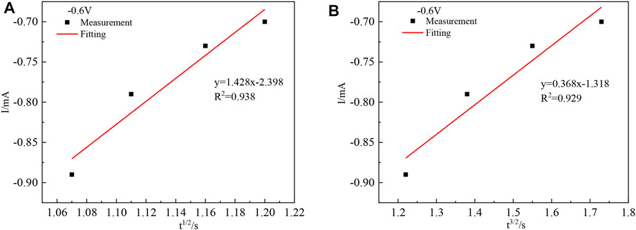
FIGURE 7. Relationship between I(t)-t1/2 (A) and I(t)-t3/2 (B).
Figure 7 shows that the goodness of fit of the fitted line (A) is greater than that of the fitted line (B), and the chronoamperometric plot is linear with the square root of time t1/2, indicating that the nucleation mechanism of indium on the titanium plate is instantaneous nucleation.
Indium Electrowinning
The cathode products were characterized by XRD and SEM techniques during the electrodeposition of Ti as a metal carrier. The test results are shown in Figure 8.

FIGURE 8. (A) XRD patterns and (B) SEM image of indium deposited on Ti electrodes.
A distinct diffraction peak for indium at 32.94° indicates a relatively pure product with good crystallinity. The Ti plating shows irregular grain morphology. During the deposition of indium with the Ti electrode, the microscopic images show uneven deposition and porous open holes with more pronounced dendrite growth, which indicates a high roughness of the cathode.
AC Impedance Analysis.
The electrochemical reaction in the cathodic process was further studied by the AC impedance method (Pettit et al., 2002). The test frequency was 5 × 10⁻³–1 × 10⁵ Hz, and the test temperature was 298 K. Z-view software is used to fit the data to obtain the corresponding equivalent circuit diagrams. Ac impedance test results are shown in Figure 9.
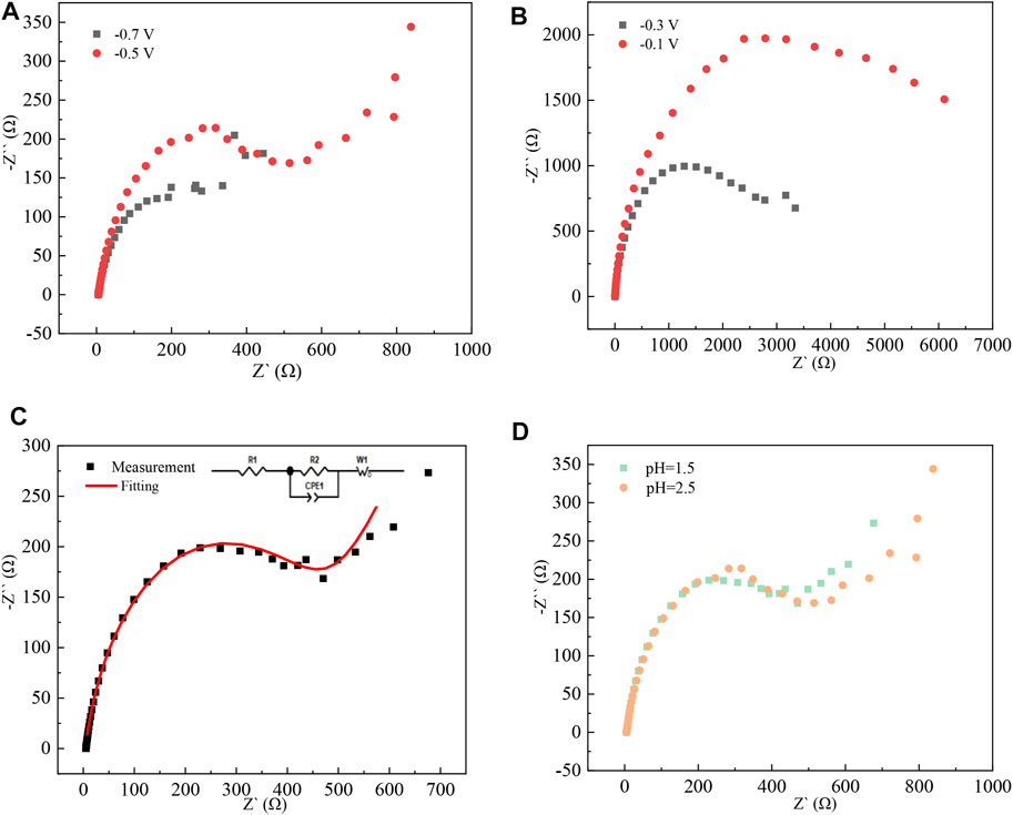
FIGURE 9. Nyquist pattern of high-purity indium prepared by electrodeposition at different pH values: (A) pH = 2.5, potential −0.7 V, −0.5 V; (B) pH = 1.5, potential −0.3 V, −0.1 V; (C) pH = 1.5, potential −0.5 V; and (D) potential of −0.5 V, pH = 1.5, 2.5
When the pH is 1.5 and the applied potential is −0.3 V and −0.1 V, there is only a capacitive arc with a large radius, indicating that the deposition of indium on the titanium plate in the indium sulfate electrolytic liquid system is an electrochemically controlled step. As the applied potential increases, the radius of the capacitive arc decreases, indicating that the deposition layer formed at the high potential is complete and that the resistance of the electrochemical reaction that occurs at this time is reduced. When the applied potential is −0.5 V and pH = 2.5, a straight line appears in the low-frequency region, indicating that the electrochemical reduction process of In3+ is subject to a diffusion-controlled step, which is consistent with the results of cyclic voltammetry tests.
Conclusion
The electrochemical behavior of In3+ was investigated by using different electrochemical methods in electrolytes containing sodium and indium sulfate. The reduction mechanism of In3+ on titanium plates is as follows: In3++3e−→In, and the electrochemical reduction process is irreversible and controlled by a diffusion step. The average diffusion coefficient of In3+ is
Data Availability Statement
The original contributions presented in the study are included in the article/Supplementary Material, further inquiries can be directed to the corresponding author.
Author Contributions
ZH made experimental plans, completed experimental work, analyzed research results, and wrote the manuscript. XW proposed the content and ideas of the manuscript research and helped analyze the experimental results. JL revised the manuscript and analyzed it. ZL guided the experimental work. YW completed part of the literature search and manuscript polishing. HX finished the grammar check. All authors listed have made a substantial, direct, and intellectual contribution to the work and approved it for publication.
Funding
This work was supported by the Regional Joint Fund project of the Liaoning Science and Technology Department (2020-YKLH-27), the Foundation of Liaoning Key Laboratory of Chemical Additive Synthesis and Separation (ZJNK 2001, ZJNK2107), and the Innovation Team Project of Yingkou Institute of Technology (TD201901).
Conflict of Interest
The authors declare that the research was conducted in the absence of any commercial or financial relationships that could be construed as a potential conflict of interest.
Publisher’s Note
All claims expressed in this article are solely those of the authors and do not necessarily represent those of their affiliated organizations, or those of the publisher, the editors, and the reviewers. Any product that may be evaluated in this article, or claim that may be made by its manufacturer, is not guaranteed or endorsed by the publisher.
References
Avchukir, K., Burkitbayeva, B. D., Argimbayeva, A. M., Rakhymbay, G. S., Beisenova, G. S., and Nauryzbayev, M. K. (2018). The Kinetics of Indium Electroreduction from Chloride Solutions. Russ. J. Electrochem. 54 (12), 1096–1103. doi:10.1134/S1023193518120042
Bardi, U., Borri, C., Lavacchi, A., Tolstogouzov, A., Trunin, E., and Trunina, O. (2009). Purification of Liquid Indium by Electric Current-Induced Impurity Migration in a Static Transverse Magnetic Field. Scripta Materialia 60 (6), 423–426. doi:10.1016/j.scriptamat.2008.11.009
Cheng, K., Yi, J., Zha, G., Fan, K., Li, Z., Kong, X., et al. (2021). Separation Behavior of as, Zn and Cd Trace Impurities in the Deep Vacuum Purification Process of Refined lead. Sep. Purif. Tech. 278, 119531. doi:10.1016/j.seppur.2021.119531
Chung, Y., and Lee, C.-W. (2013). Nucleation Process of Indium on a Copper Electrode. J. Electrochem. Sci. Technol. 4 (3), 93–101. doi:10.5229/JECST.2013.4.3.9310.33961/jecst.2013.4.3.93
Ciro, E., Dell'Era, A., Pasquali, M., and Lupi, C. (2021). Indium Electrowinning Kinetics on Titanium, Aluminum and Copper Supports from Sulfate Solution. J. Electroanalytical Chem. 885, 115099. doi:10.1016/j.jelechem.2021.115099
Ciro, E., Dell'Era, A., Pasquali, M., and Lupi, C. (2020). Indium Electrowinning Study from Sulfate Aqueous Solution Using Different Metal Cathodes. J. Environ. Chem. Eng. 8 (2), 103688. doi:10.1016/j.jece.2020.103688
Dell'Era, A., Ciro Zuleta, E., Pasquali, M., and Lupi, C. (2020). Process Parameters Affecting the Efficiency of Indium Electrowinning Results from Sulfate Baths. Hydrometallurgy 193, 105296. doi:10.1016/j.hydromet.2020.105296
Eliaz, N., and Sridhar, T. M. (2008). Electrocrystallization of Hydroxyapatite and its Dependence on Solution Conditions. Cryst. Growth Des. 8 (11), 3965–3977. doi:10.1021/cg800016h
Fontana, D., Forte, F., De Carolis, R., and Grosso, M. (2015). Materials Recovery from Waste Liquid crystal Displays: A Focus on Indium. Waste Manag. 45, 325–333. doi:10.1016/j.wasman.2015.07.043
Kang, H., Li, J., Zhang, C., Lu, J., Wang, Q., and Wang, Y. (2020). Study of the Electrochemical Recovery of Cobalt from Spent Cemented Carbide. RSC Adv. 10 (37), 22036–22042. doi:10.1039/D0RA02602F
Kang, H. N., Lee, J.-Y., and Kim, J.-Y. (2011). Recovery of Indium from Etching Waste by Solvent Extraction and Electrolytic Refining. Hydrometallurgy 110 (1-4), 120–127. doi:10.1016/j.hydromet.2011.09.009
Katiyar, P. K., and Randhawa, N. S. (2020). A Comprehensive Review on Recycling Methods for Cemented Tungsten Carbide Scraps Highlighting the Electrochemical Techniques. Int. J. Refractory Met. Hard Mater. 90, 105251. doi:10.1016/j.ijrmhm.2020.105251
Li, J., Fei, X., and Xiang, C. (2006). Preliminary Study on Process Kinetics of Sulphuric Acid Indium Plating Electrode. Mater. Prot. 39 (6), 3. doi:10.16577/j.cnki.42-1215/tb.2006.06.004
Li, M., Sun, Z., Guo, D., Han, W., Sun, Y., Yang, X., et al. (2020). Electrode Reaction of Pr(III) and Coreduction of Pr(III) and Pb(II) on W Electrode in Eutectic LiCl-KCl. Ionics 26 (8), 3901–3909. doi:10.1007/s11581-020-03518-4
Li, M., Xi, X., Liu, Q., Nie, Z., and Ma, L. (2019). Direct Electrolytic Separation of Tungsten and Cobalt from Waste Cemented Carbide and Electrochemical Behavior of Tungsten and Cobalt Ions in NaF-KF Molten Salts. J. Electroanalytical Chem. 833, 480–489. doi:10.1016/j.jelechem.2018.12.032
Liu, G. (2010). Study on Purification Technology of Crude Indium. Nonferrous Mining Metall. 26 (01), 35–37. doi:10.3969/j.issn.1007-967X.2010.01.011
Liu, K., tan, T., Zhou, X., Zheng, N., Ma, Y., Kang, M., et al. (2021). The Dendrite Growth, Morphology Control and Deposition Properties of Uranium Electrorefining. J. Nucl. Mater. 555, 153110. doi:10.1016/j.jnucmat.2021.153110
Liu, Z., Lu, G., and Yu, J. (2021). Investigation on Electrochemical Behaviors of Ni(II) Impurity in LiCl-KCl Melt. Sep. Purif. Tech. 268, 118354. doi:10.1016/j.seppur.2021.118354
Lobaccaro, P., Raygani, A., Oriani, A., Miani, N., Piotto, A., Kapadia, R., et al. (2014). Electrodeposition of High-Purity Indium Thin Films and its Application to Indium Phosphide Solar Cells. J. Electrochem. Soc. 161 (14), D794–D800. doi:10.1149/2.0821414jes
Luo, H., Jiang, W., Zha, G., Liu, L., Zhen, T., Yang, B., et al. (2022). Removal of Impurity Pb during Crude Selenium Purification by Controlling Potential Oxidation and Vacuum Distillation. Vacuum 195, 110674. doi:10.1016/j.vacuum.2021.110674
Pettit, C. M., Garland, J. E., Etukudo, N. R., Assiongbon, K. A., Emery, S. B., and Roy, D. (2002). Electrodeposition of Indium on Molybdenum Studied with Optical Second Harmonic Generation and Electrochemical Impedance Spectroscopy. Appl. Surf. Sci. 202 (1-2), 33–46. doi:10.1016/S0169-4332(02)00798-5
Rajska, D., Brzózka, A., Hnida-Gut, K. E., and Sulka, G. D. (2021). Investigation of Electrodeposition Kinetics of in, Sb, and Zn for Advanced Designing of InSb and ZnSb Thin Films. J. Electroanalytical Chem. 882, 114967. doi:10.1016/j.jelechem.2020.114967
Rakhymbay, G., Nauryzbayev, M. K., Burkitbayeva, B. D., Argimbaeva, A. M., Jumanova, R., Kurbatov, A. P., et al. (2016). Electrochemical Deposition of Indium: Nucleation Mode and Diffusional Limitation. Russ. J. Electrochem. 52 (2), 99–105. doi:10.1134/S1023193516020087
Shelke, A. R., Balwada, J., Sharma, S., Pingale, A. D., Belgamwar, S. U., and Rathore, J. S. (2020). Development and Characterization of Cu-Gr Composite Coatings by Electro-Co-Deposition Technique. Mater. Today Proc. 28, 2090–2095. doi:10.1016/j.matpr.2020.03.244
Walsh, F. C., and Gabe, D. R. (1981). The Electrodeposition of Indium. Surf. Tech. 13 (2), 305–314. doi:10.1016/0376-4583(79)90054-210.1016/0376-4583(81)90104-7
Xiao, X., Xi, X., Nie, Z., Zhang, L., and Ma, L. (2017). Direct Electrochemical Preparation of Cobalt, Tungsten, and Tungsten Carbide from Cemented Carbide Scrap. Metall. Materi Trans. B 48 (1), 692–700. doi:10.1007/s11663-016-0836-1
Xu, S., Wang, G., Fan, J., Wang, Z., Zhang, J., Chen, J., et al. (2021). Preparation of High Purity Indium by Chemical Purification: Focus on Removal of Cd, Pb, Sn and Removal Mechanism. Hydrometallurgy 200, 105551. doi:10.1016/j.hydromet.2020.105551
Xu, Y., Zhu, Z., Liu, L., and Liu, Z. (2021). Electrochemical Study of Nickel Nucleation Mechanisms on Glassy Carbon at Different pH Values in an Industrial Electrolyte. Int. J. Mater. Res. 112 (2), 143–149. doi:10.1515/ijmr-2020-8046
Yu, L., Jiang, W., Fu, Z., Guo, R., and Li, T. (2013). Study on Electrorefining Method of Indium. Mater. Rev. 27 (04), 16–19. doi:10.3969/j.issn.1005-023X.2013.04.005
Zhang, P., O'Keefe, T. J., and Yu, P. (2001). Electrochemical Characterization of the Effects of Impurities and Organic Additives in lead Electrowinning from Fluoborate Electrolyte. Hydrometallurgy 61 (3), 207–221. doi:10.1016/S0304-386X(01)00175-X
Keywords: indium, electrodeposition, indium sulfate, cyclic voltammetry, nucleation mechanism
Citation: Hou Z, Wang X, Li J, Li Z, Wang Y and Xing H (2022) Electrochemical Mechanism of the Preparation of High-Purity Indium by Electrodeposition. Front. Chem. 10:871420. doi: 10.3389/fchem.2022.871420
Received: 08 February 2022; Accepted: 21 March 2022;
Published: 24 May 2022.
Edited by:
Elizabeth J. Podlaha, Clarkson University, United StatesReviewed by:
Pravin Shinde, University of Alabama, United StatesAnmin Liu, Dalian University of Technology, China
Copyright © 2022 Hou, Wang, Li, Li, Wang and Xing. This is an open-access article distributed under the terms of the Creative Commons Attribution License (CC BY). The use, distribution or reproduction in other forums is permitted, provided the original author(s) and the copyright owner(s) are credited and that the original publication in this journal is cited, in accordance with accepted academic practice. No use, distribution or reproduction is permitted which does not comply with these terms.
*Correspondence: Xiaomin Wang, dHkuY29tLmNuQDEyNi5jb20=