- 1State Key Laboratory of Offshore Oil and Gas Exploitation, Beijing, China
- 2CNOOC Research Institute Ltd., Beijing, China
- 3CNOOC Ener Tech-Drilling & Production Co., Tianjin, China
Natural gas flooding represents a significant technique for the enhancement of oil recovery, thereby facilitating the efficient utilization of oil and gas resources. In the injection and production system, the throttling gas nozzle is a key component that adjust the injection pressure according to the reservoir’s pressure. However, current throttling gas nozzles utilize a fixed structure, which presents a challenge in achieving online control of flow rate and pressure drop. Therefore, a new adjustable multi-hole throttling device was proposed in this paper, allowing for the regulation of pressure loss by changing the number of flowing holes. In order to gain insight into the operational principles and pressure drop characteristics of this new throttling device, the SST k-ω turbulence model and the NIST physical property model were employed to simulate the supercritical natural gas flow in the nozzle. The results demonstrate that there is an uneven distribution of velocity between the channels of the downhole multi-hole throttling device. The velocity in a single nozzle channel exhibits a trend of initially increasing rapidly and then decreasing, while the pressure exhibits an initial decrease, which is then followed by a slight increase. The pressure drops of the nozzle under different flow rates and flowing hole numbers were acquired, revealing that the pressure drop of the multi-hole throttling device is inversely proportional to the number of holes. The adjustment accuracy of pressure drop and flow rate is higher when the number of holes is between 4 and 6. However, a significant increase in pressure drop occurs when the number of holes is less than 3, resulting in poorer regulation accuracy. Furthermore, a pressure drop prediction model was developed based on the numerical results, which provides guidance for the application and design of the throttling device. In this study, a new natural gas flooding throttling device is proposed, offering a new approach for downhole equipment development. Additionally, this research provides guidance for the practical application and iterative improvement of this throttling device in future use.
1 Introduction
The development of oil and gas exploration has led to an increased significance of low-permeability reservoirs. Consequently, the method of using gas injection for low-permeability reservoirs is receiving greater attention (Zhang et al., 2024; Liu et al., 2024; Li et al., 2023; Tang et al., 2022; Bayat et al., 2016). The most common methods of gas flooding include nitrogen flooding, oxygen-reduced air flooding, CO2 flooding, and natural gas flooding. The injection of these gases into the oil layer has the potential to enhance the driving force, which may result in mixed-phase displacement or improved oil mobility, thereby increasing production efficiency (Seyyedsar et al., 2015; Kalra and Wu, 2014; Pei et al., 2006; Yu et al., 2022; Zhang et al., 2023). Compared with conventional water flooding and gas flooding, natural gas flooding has the potential to significantly enhance crude oil recovery (Yuan et al., 2024). As an associated gas source, natural gas is a promising means to enhance recovery in low-permeability oil fields due to its relative abundance.
During the natural gas flooding process, precise control of injection pressure is essential. Excessive injection pressure may result in damage to the formation, whereas insufficient injection pressure may prevent the injected gas from effectively entering the formation and achieving the goal of enhanced recovery. The throttling gas nozzle is of critical importance in the regulation of injection pressure throughout the process. (Zhang et al., 2023; Fu et al., 2020). Consequently, an investigation into the pressure drop of the nozzle can facilitate the optimization of its utilization, thereby enabling the regulation of injection pressure and volume, enhancing oilfield extraction efficiency, extending well lifespan, and achieving sustainable energy utilization.
Some scholars have conducted research on the characteristics of nozzle pressure drops. Vree et al. (2015) conducted experimental studies on the flow field characteristics of CO2 passing through nozzles with diameters of 3 mm, 6 mm, and 12 mm. Li et al. (2016)examined the pressure drop of CO2 flowing through nozzles with diameters ranging from 0.1 mm to 5 mm, as well as the flow characteristics in the vicinity of the nozzles. Huang and Hu (2022) studied the influence of varying length-to-diameter ratios of the nozzle on CO2 choked flow. Furthermore, some scholars have examined the influence of nozzle structural dimensions on the flow field with regard to temperature distribution (Qiao et al., 2024; Zhang et al., 2023; Li et al., 2022). Besides these single-hole nozzle structures, some scholars have also investigated some new nozzle structures. Huang et al. (2022) proposed an axially movable valve control nozzle structure, which enables real-time modification of the flow channel from a single hole to eight holes. Wan et al. (2016)employed a numerical method to examine a four-stage serial nozzle structure, elucidating the flow field distribution characteristics within the nozzle and the impact of varying nozzle parameters on throttling pressure drop. Wang et al. (2018) reported the flow field characteristics of CO2 flowing through nozzles under varying stages and diameters, with pressure drops ranging from 5 MPa to 25 MPa. Li (2021) studied the flow field characteristics of supercritical CO2 through a three-stage eccentric nozzle, providing the nozzle’s pressure drop coefficient. Tang et al. (2024) investigated the flow field characteristics of a multi-stage nozzle controlled by a valve core, identifying the relationship between pressure drop and opening. Zhang et al. (2022) proposed a multi-stage pressure-reducing valve and studied the distribution of velocity and pressure.
Previous scholars have conducted experimental and numerical studies on the pressure drop characteristics and internal flow field distribution features. However, most of the nozzle structures are fixed and unable to be adjusted in real-time based on actual downhole operational data, injection reservoir pressure, flow rate, and other parameters, thus failing to meet the practical production needs of the industry. It is inevitable that the flow rate and the reservoir pressure requirements will undergo continual change with the extraction process, thereby necessitating corresponding adjustments to the pressure drop. Therefore, a new adjustable multi-hole throttling nozzle structure is proposed in this paper that utilizes the interaction between rotating and fixed components to achieve rapid regulation of pressure drop characteristics, thereby ensuring the long-term stable operation of the gas flooding reinjection system. Furthermore, to gain additional insight into the pressure drop characteristics of the proposed multi-hole throttling nozzle, this paper employs a numerical method, referencing actual downhole natural gas parameters, to study the flow field characteristics of the nozzle and its loss characteristics under different conditions and opening hole numbers. Additionally, a correlation was established to predict the pressure drop and to provide guidance on the practical application and adjustment strategy of the nozzle.
2 Numerical simulation method
2.1 Geometric model
The geometric model of the adjustable multi-hole throttling device studied in this paper is shown in Figure 1, with the main structural components labeled. It mainly consists of a rotating section, gas nozzle channels, and a fixed part comprising an annular flow region and a side outlet. In practical applications, the angle between the rotating section and the fixed gas nozzle channel can be varied by rotating the front section, thereby enabling the control of different flow hole numbers and the adjustment of pressure drop characteristics. The main parameters of the nozzle structure are presented in Table 1.
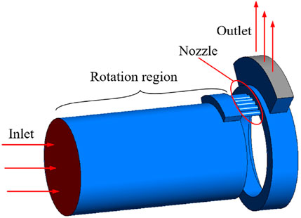
Figure 1. Geometrical structure of the downhole multi-hole throttling device with key components labeled.
2.2 Numerical model
Based on actual gas well conditions, the working fluid employed in this study was a mixture of gases comprising 10% CO2 and 90% CH4. Figure 2 illustrates the phase diagram of the mixed gases, which was calculated using the gas physical property model from the National Institute of Standards and Technology (NIST), alongside the actual operating conditions of the downhole nozzle. Compared to other physical property calculation models, the NIST model is optimized based on a vast amount of experimental data. In contrast to other models derived from theoretical principles, the NIST model provides higher accuracy in calculating the properties of mixtures, making it a widely recognized standard in the field (Lemmon et al., 2013; Patil et al., 2007; Aute and Radermacher, 2014). It can be observed that within the specified operational parameters, the phase region of the mixed gas is situated within the single-phase supercritical region, exhibiting no evidence of two-phase states. Accordingly, a single-phase numerical framework was utilized.
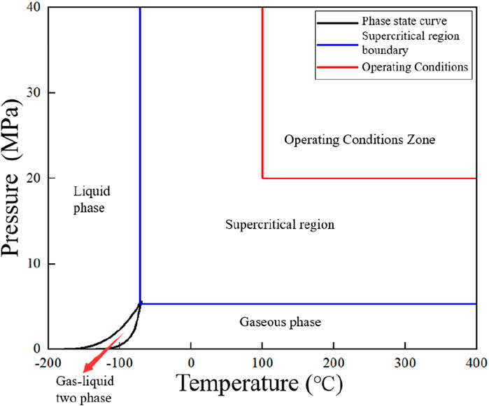
Figure 2. Phase state curve of carbon dioxide and methane mixtures: Including working condition areas.
Selecting an appropriate turbulence model is crucial for ensuring the accuracy of the numerical results. The throttling device features significant variations in flow channel and flow field characteristics. The SST k-ω turbulence model combines the advantages of the k-ε turbulence model, which is suitable for high Reynolds number flows, and the k-ω model, which is effective for low Reynolds number flows near the wall (Jones and Launder, 1972; Menter, 1993; Menter, 1994). This model is capable of accurately capturing the local pressure losses from sudden contractions and expansions in the throttling nozzle, as well as the frictional resistance within the channels (Zeng et al., 2023). By comparison, the k-ε model requires the introduction of wall functions when dealing with near-wall regions, which may lead to a decrease in calculation accuracy. On the other hand, the RSM model has a higher computational complexity and requires more computational resources. Therefore, this paper adopts the SST k-ω turbulence model, and its governing equations are as follows,
In Equations 1, 2,
The boundary of the numerical model includes an inlet and an outlet. According to actual physical conditions, the inlet is set as a mass flow inlet, while the outlet is defined as a pressure outlet. The properties of the mixed fluid are selected using the gas property calculation model from the National Institute of Standards and Technology (NIST). All wall surfaces are set as no-slip walls. The solver employs the COUPLE algorithm to resolve the pressure-velocity field, utilizing the PRESTO! pressure discretization format and a higher-order QUICK scheme for the discretization of momentum and energy.
2.3 Mesh generation
The mesh for the fluid domain of the downhole throttling device is primarily based on hexahedral cells, with local refinements applied in regions exhibiting significant changes in the flow field. This approach ensures the capture of flow field characteristics. Furthermore, boundary layers are established in all near-wall regions to account for flow boundary effects, thus ensuring that y+ ≤ 1 and meeting the requirements for boundary layer grids in the SST k-ω model. A schematic diagram of the established mesh model is shown in Figure 3.
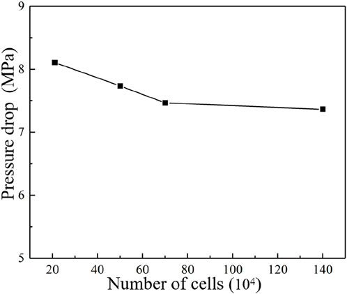
In order to ascertain a mesh quantity that is both computationally accurate and economically efficient, a mesh independence verification was conducted. The same numerical model and boundary conditions were employed in the calculation of four distinct models, each exhibiting a varying grid density. It can be seen from Figure 4 that when the pressure drop has a slight change of approximately 1% between the cell number of 700,000 and 1,400,000. Consequently, a mesh model with 700,000 cells is selected for subsequent simulation.
2.4 Model Validation
Experimental data from reference (Li, 2020) was used to validate the accuracy of the numerical model. A comparison between the numerical results and the experimental results from the literature is presented in Table 2. The discrepancy between the numerical results and the experimental data is less than 3%, which demonstrates that the numerical model is capable of accurately simulating the pressure drop characteristics of the nozzle.

Table 2. Comparison between experimental results (Li, 2020)and numerical results.
3 Results and discussion
3.1 Flow field characteristics
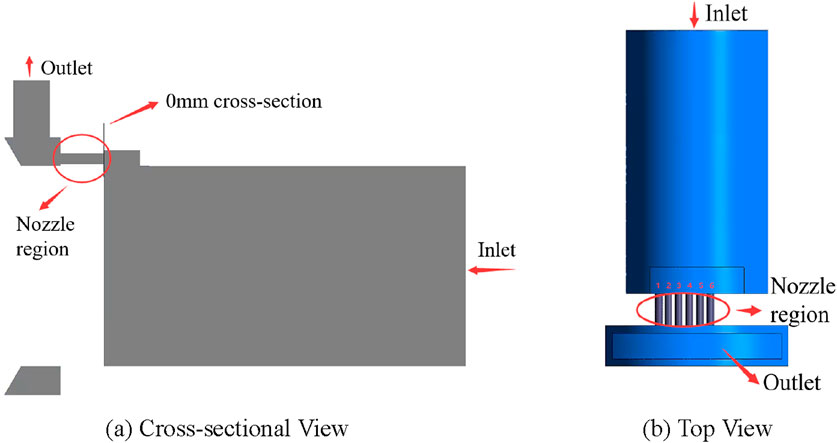
Analyzing the flow field characteristics of the throttling device is beneficial for a more comprehensive understanding of its operational mechanism. A flow characteristic analysis was conducted under the working conditions with a flow rate of 30,000 Nm³/d, pressure of 20 MPa, and temperature of 100°C. Figure 5A depicts a cross-sectional view of the throttling device, with the inlet situated on the right side and the outlet positioned in the upper left. A reference section is established at a relative position of 0 mm on the inlet side, specifically to the right of the nozzle area. For the purposes of this analysis, the leftward direction is considered positive and the rightward direction is considered negative. Figure 5B depicts a top view of the throttling device, wherein the channels within the nozzle area are sequentially labeled from No. 1 to No. 6, from left to right.
Figure 6 illustrates the streamline distribution within various nozzle configurations. The fluid flows into the device from the inlet, then turns upward into the nozzle area. In the lower part of the device, a recirculation region was observed to be present. The radial velocity of the fluid entering the nozzle area, caused by the inertial force, results in a high-speed flow that is predominantly concentrated in the upper half of the nozzle, forming a sickle-shaped distribution.
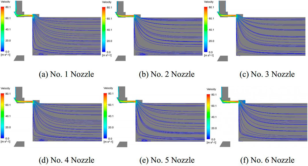
Figure 6. Streamline diagrams at different nozzles. (A) No. 1 nozzle. (B) No. 2 nozzle. (C) No. 3 nozzle. (D) No. 4 nozzle. (E) No. 5 nozzle. (F) No. 6 nozzle.
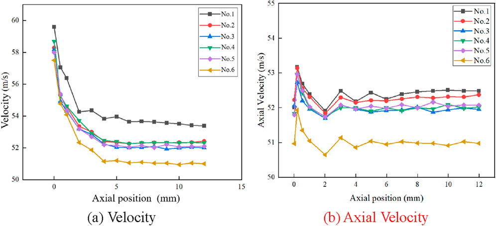
The velocity distribution within the different nozzle channels is shown in Figure 7. It can be observed that the fluids exhibit an initial acceleration prior to entering the nozzle. As the fluid flows into the nozzle, the abrupt reduction in the cross-sectional area of the flow passage results in a significant increase in velocity. Subsequently, the fluids leave the nozzles and enter the wide region, where they undergo a rapid deceleration. Figure 8A illustrates the velocity profile within the six nozzle channels. Prior to the 5 mm position, a discernible reduction in velocity is observed, which then remains relatively constant beyond that point. The velocity profile within the six nozzle channels reveals that the No. 1 nozzle exhibits the highest velocity, while the velocities in channels No. 2 to No. 5 demonstrate minimal variation, with the lowest velocity observed in No. 6.
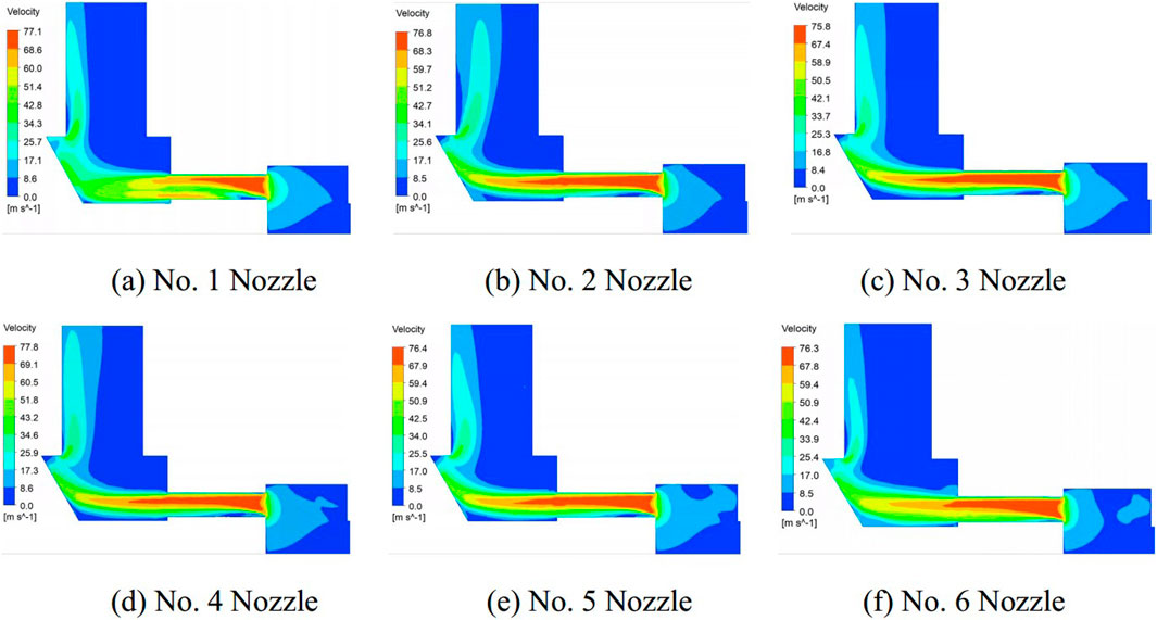
Figure 7. Velocity contour diagrams at different nozzles. (A) No. 1 nozzle. (B) No. 2 nozzle. (C) No. 3 nozzle. (D) No. 4 nozzle. (E) No. 5 nozzle. (F) No. 6 nozzle.
Figure 8B depicts the axial velocity profiles in the six nozzle channels. Upon initial entry into the nozzle, the axial velocity of the fluid exhibits a notable increase, which subsequently declines before exhibiting a gradual stabilization after reaching the 5 mm position. In channels 1 to 5, the axial velocity is relatively consistent, whereas channel 6 exhibits the lowest axial velocity. From Figures 7, 8, it can be observed that the fluid exhibits both axial and radial velocities. The formation of a vortex in front of the No. 1 nozzle channel results in the highest velocity among all the nozzles. Meanwhile, the sixth channel, situated at the point of fluid acceleration, exhibits the lowest velocity and axial velocity in comparison to the other nozzle channels. In the region of contraction within the nozzle, a considerable radial velocity is observed. After the 5 mm position, only axial velocity is observed.
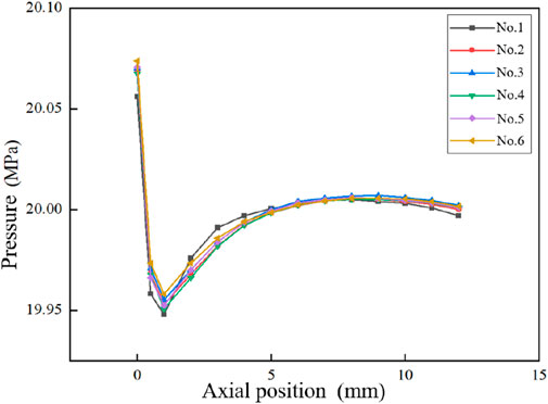
Figure 9 illustrates the distribution of static pressure within the six nozzle channels. Referring to the axial velocity distribution in Figure 8B, the axial velocity distribution indicates that at the initial stage of entering the nozzle, the axial velocity of the fluid increases, while the static pressure decreases, falling below the outlet pressure (20 MPa). Subsequently, the static pressure of the fluid begins to rise as a result of the back pressure, reaching a point of stability at 20 MPa. Meanwhile, the axial velocity decreases and stabilizes as the flow develops, which is similar with the results of Gulsacan (2024)and Wu (2022).
3.2 Effect of inlet flow rate
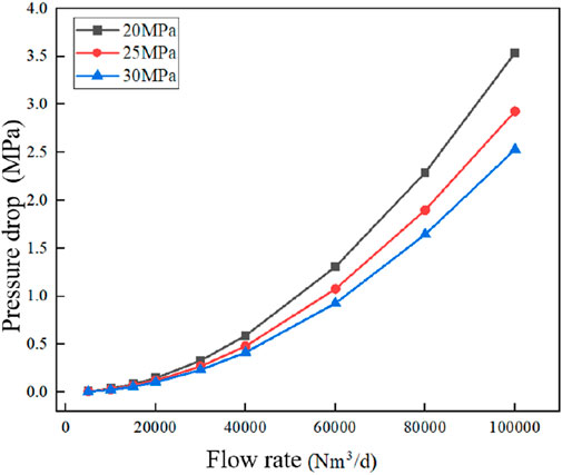
Figure 10 depicts the alteration in pressure drop across the nozzle with fluctuating inlet flow rates when all six holes are fully opened. It can be observed that as the flow rate increases, the pressure drop of the throttling device exhibits a parabolic growth trend. This is principally due to the fact that the total pressure drop within the throttling device during the flow process is constituted of both the frictional pressure drop and the local pressure drop. The frictional and local pressure drops are proportional to the square of the velocity. Consequently, as the flow rate increases, the pressure drop gradually increases, resulting in a parabolic growth pattern.
Figure 11 the velocity distribution contour at varying flow rate conditions. It can be observed that as the flow rate increases, the velocity distribution trends in the nozzle region exhibit a high degree of similarity. Prior to reaching the nozzle, the fluid undergoes an acceleration process, reaching its maximum velocity within the entire fluid domain upon entering the nozzle area. The increase in maximum velocity is directly proportional to the increase in flow rate. The maximum velocity increases from 25 m/s to 240 m/s when inlet flow rate changes from 10,000 Nm3/d to 100,000 Nm3/d. Additionally, as the maximum flow velocity increases, the flow pattern in the outlet region undergoes some changes. When the flow rate reaches 100,000 Nm³/d, the high velocity at the outlet causes the fluid to be reflected back after contacting the sloped outlet wall, and then it flows out along the opposite side of the outlet wall.

Figure 11. Velocity distribution in the nozzle at different flowrate. (A) 10000Nm3/d. (B) 60000Nm3/d. (C) 100000Nm3/d.
3.3 Effect of flowing hole number
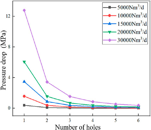
The adjustment of the throttling characteristics of the device is achieved by modifying the number of open holes. Therefore, it is necessary to investigate the effect of the hole number on its flow field characteristics. Figure 12 shows the impact of varying flow hole numbers under conditions of 20 MPa pressure and 140°C temperature. It can be observed that, with a constant inlet flow rate, a reduction in the number of openings results in a gradual increase in pressure drop, accompanied by an elevated change rate in pressure drop. Upon adjusting the number of holes from 6 to 5 and from 5 to 4, the pressure drop exhibited a 1.44-fold and 1.57-fold increase, respectively. Conversely, when the number of holes is altered from three to two, and from two to one, the pressure drop increases by a factor of 2.31 and 4.03, respectively. This suggests that when the number of openings is reduced from six to four, the change in pressure drop is relatively minor, thereby enabling a higher degree of precision in pressure drop adjustment by the throttling device. Nevertheless, as the number of openings decreases from three to one, the rate of change in pressure drop markedly increases, reducing the precision of pressure drop adjustment.
Furthermore, as the injection rate increases, the range of pressure drop adjustments also expands. For example, at an injection rate of 5,000 Nm³/d, the adjustment range is from 0.0107 MPa to 0.3968 MPa, whereas at 30,000 Nm³/d, it ranges from 0.3826 MPa to 12.7903 MPa, representing a 32-fold increase in the adjustment range relative to 5,000 Nm³/d. Further analysis of the results reveals a proportional relationship between the pressure drop of the throttling device and the ratio of flow to the number of holes. For instance, a flow of 10,000 Nm³/d with a single opening, 20,000 Nm³/d with two opening holes, and 30,000 Nm³/d with three openings, respectively, result in pressure drops of 1.5753 MPa, 1.5611 MPa, and 1.5392 MPa. This finding lays the groundwork for establishing future predictive relationships for pressure drops.
The velocity field distribution in the throttling devices with different numbers of holes is shown in Figure 13, with the right side indicating the direction of flow. It can be observed that the velocity increases prior to entering the nozzle area and reaches its peak within the nozzle. Upon entering the nozzle, the velocity in the lower half of the nozzle decreases, with the range of velocity reduction increasing with the increase in axial position increases.
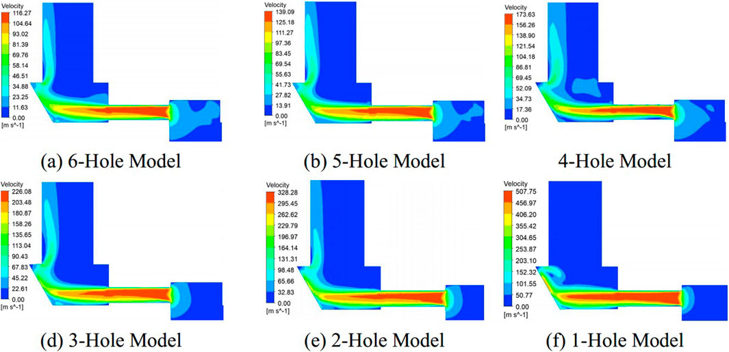
Figure 13. Velocity contour of nozzle with different number of holes. (A) 6-holes model. (B) 5-holes model. (C) 4-holes model. (D) 3-holes model. (E) 2-holes model. (F) 1-holes model.
After exiting the nozzle area, the fluid undergoes two turns: first at the inclined outlet wall and then at the outlet. In the case of a hole count ranging from 2 to 6, the fluid exits the outlet after undergoing two deflections. In contrast, the fluid in the one-hole model undergoes a horizontal deflection when it flows over the protruding part.
With regard to the magnitude of the velocity, it is observed that as the number of holes is reduced, the peak velocity within the nozzle increases gradually. A comparison of the peak velocities when adjusting from 6 holes to 5 holes and from 5 holes to 4 holes reveals an increase of 1.18-fold and 1.24-fold, respectively. Conversely, when the number of holes is reduced from three to two, or from two to one, the peak velocity increases by 1.45-fold and 1.55-fold, respectively.
This indicates that in models comprising four to six holes, the throttling device is capable of more precise velocity adjustment, whereas in models with one to three holes, the accuracy of velocity adjustment is reduced.
3.4 Prediction correlations of pressure drop
It is important to accurately predict the pressure drop across the throttling device in downhole conditions in order to ensure its effective application. A functional correlation was established between pressure drop, opening channel area, outlet pressure, and inlet flow rate based on the numerical database. As evidenced by the preceding analysis, the precision with which the pressure drop of the throttling device can be adjusted varies considerably with the number of openings. Consequently, two equations were formulated for models comprising one to three holes and those with four to six holes, respectively. The correlations established are as follows,
In Equation 3,
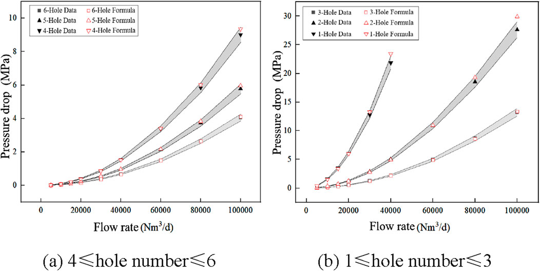
The pressure drops across the throttling device under different operating conditions were calculated and the results were compared with the simulation calculations to verify the accuracy of the prediction correlation. The comparative results are shown in Figure 14. It can be seen that the predicted results agree well with the numerical results. Within the range of pressures from 20 to 30 MPa and flow rates from 5,000 to 100,000 Nm³/d, the relative error of more than 95% results are less than 5%.
4 Conclusion
In order to achieve effective pressure control during natural gas injection and production, a new adjustable multi-hole throttling device is proposed in this paper. The supercritical flow within the device was simulated using the SST k-ω turbulence model and the NIST physical property model. Furthermore, the flow field and throttling characteristics at varying inlet flow rates and flowing nozzles were examined through numerical analysis. Additionally, a correlation was developed to predict the pressure drop. Based on discussion above, conclusions are as follows.
(1) An uneven distribution of flow rates among the nozzle channels of the throttling device was observed. The velocity in Channel 1 is the highest among the six channels, while Channel 6 exhibits the lowest velocity.
(2) When the fluid passes through the contraction region before entering the nozzle, it undergoes expansion and acceleration, resulting in a reduction in pressure. Subsequently, the pressure increases gradually, while the velocity decreases toward stabilization.
(3) The numerical results at different flowing nozzles indicate that, for a fixed inlet flow rate, the throttling device maintains high precision in regulating both pressure drop and velocity when adjusting from 6 to 4 holes. Conversely, precision decreases significantly when adjusting from 3 to 1 hole.
(4) Based on the numerical database, correlations to predict pressure drop were established between opening hole number, inlet flow rate, and outlet pressure. These correlations show a good agreement at the operating pressure range of 20–30 MPa and flow rates from 5,000 to 100,000 Nm³/d.
In the current downhole gas injection methods, the design of the adjustable gas nozzle allows the device to achieve layered gas injection within a single well tubing over a wide range of flow rates and pressures, while also enabling real-time flow regulation downhole, reducing the need for multiple fishing operations. In future research, enhancements to the existing computational models could be pursued to simulate real-world conditions, such as potential nozzle erosion, dynamic reservoir pressure variations, and multiphase flow within the nozzle.
Data availability statement
The raw data supporting the conclusions of this article will be made available by the authors, without undue reservation.
Author contributions
XX: Writing–original draft, Methodology. HC: Writing–review and editing, Conceptualization. YM: Validation, Writing–original draft. JY: Formal analysis, Writing–review and editing. DX: Conceptualization, Writing–review and editing. MZ: Methodology, Writing–review and editing. LK: Supervision, Writing–review and editing.
Funding
The author(s) declare that no financial support was received for the research, authorship, and/or publication of this article.
Conflict of interest
Authors XX, HC, YM, JY, and MZ were employed by CNOOC Research Institute Ltd.
Authors DX and LK were employed by CNOOC Ener Tech-Drilling&Production Co.
Publisher’s note
All claims expressed in this article are solely those of the authors and do not necessarily represent those of their affiliated organizations, or those of the publisher, the editors and the reviewers. Any product that may be evaluated in this article, or claim that may be made by its manufacturer, is not guaranteed or endorsed by the publisher.
References
Aute, V., and Radermacher, R. (2014). “Standardized polynomials for fast evaluation of refrigerant thermophysical properties,” in International refrigeration and air conditioning conference. International refrigeration and air conditioning conference.
Bayat, M., Lashkarbolooki, M., Hezave, A. Z., and Ayatollahi, S. (2016). Investigation of gas injection flooding performance as enhanced oil recovery method. J. Nat. Gas. Sci. Eng. 29, 37–45. doi:10.1016/j.jngse.2015.12.047
Fu, Y., Ma, H., Yu, C., Dong, L., Yang, Y., Zhu, X., et al. (2020). Analysis of effective operation performance of wireless control downhole choke. Shock Vib. 2020, 1–12. doi:10.1155/2020/7831819
Gulsacan, B., Tokgoz, N., Karakas, E. S., Aureli, M., and Evrensel, C. A. (2024). Effect of orifice thickness-to-diameter ratio on turbulent orifice flow: an experimental and numerical investigation. Int. Commun. Heat. Mass Transf. 151, 107213. doi:10.1016/j.icheatmasstransfer.2023.107213
Huang, J., Wang, Y., Huang, Y., Zhou, Y., Tian, G., and Wang, J. (2022). Effect of geometry and upstream stagnation thermodynamic parameters on CO2 choked flow through orifices. Ann. Nucl. Energy. 165, 108789. doi:10.1016/j.anucene.2021.108789
Huang, X., and Hu, S. (2022). Simulation and experimental study on flow characteristics of hydraulic valve nozzle(in Chinese). Oil Field Equip. 51 (3), 60–64.
Jones, W. P., and Launder, B. E. (1972). The prediction of laminarization with a two-equation model of turbulence. Int. J. Heat. Mass Transf. 15, 301–314. doi:10.1016/0017-9310(72)90076-2
Kalra, S., and Wu, X. (2014). “CO2 injection for enhanced gas recovery,” in SPE western north American and rocky mountain joint meeting. SPE western north American and rocky mountain joint meeting.
Lemmon, E. W., Huber, M. L., and Mclinden, M. O. (2013). NIST reference fluid thermodynamic and transport properties — REFPROP.
Li, C., Zhang, C., Li, Z., and Jia, W. (2022). Numerical study on the condensation characteristics of natural gas in the throttle valve. J. Nat. Gas. Sci. Eng. 104, 104689. doi:10.1016/j.jngse.2022.104689
Li, D., Saraji, S., Jiao, Z., and Zhang, Y. (2023). An experimental study of CO2 injection strategies for enhanced oil recovery and geological sequestration in a fractured tight sandstone reservoir. Geoenergy Sci. Eng. 230, 212166. doi:10.1016/j.geoen.2023.212166
Li, K., Zhou, X., Tu, R., Xie, Q., Yi, J., and Jiang, X. (2016). An experimental investigation of supercritical CO2 accidental release from a pressurized pipeline. J. Supercrit. Fluids 107, 298–306. doi:10.1016/j.supflu.2015.09.024
Li, P. (2020). Supercritical CO2 flooding nozzle flow characteristics and split injection process research(in Chinese). Hubei, China: Yangtze University.
Li, X. (2021). Research on supercritical CO_2 separate layer injection technology in ultra-low permeability reservoirs(in Chinese). Oil Prod. Eng. (02), 79–100.
Liu, L., Shi, M., Wang, J., Wang, W., Su, Y., and Zhuang, X. (2024). Optimization of gas-flooding fracturing development in ultra-low permeability reservoirs. Fluid Dyn. Mater. Process. 20 (3), 595–607. doi:10.32604/fdmp.2023.041962
Menter, F. R. (1993). “Zonal two equation k-w turbulence models for aerodynamic flows,” in 23rd fluid dynamics, plasmadynamics and lasers conference. 23rd fluid dynamics, plasmadynamics, and lasers conference.
Menter, F. R. (1994). Two-Equation eddy-viscosity turbulence models for engineering applications. AIAA J. 32, 1598–1605. doi:10.2514/3.12149
Patil, P., Ejaz, S., Atilhan, M., Cristancho, D., Holste, J. C., and Hall, K. R. (2007). Accurate density measurements for a 91% methane natural gas-like mixture. J. Chem. Thermodyn. 39 (8), 1157–1163. doi:10.1016/j.jct.2007.01.002
Pei, X., Yang, Z., Ban, L., and Liang, Y. (2006). “History and actuality of separate layer oil production technologies in daqing oilfield,” in International oil & gas conference and exhibition in China. International oil & gas conference and exhibition in China. SPE-100859-MS.
Qiao, M., Jing, Z., Zhou, R., Chen, C., Zou, X., Li, Y., et al. (2024). The throttling characteristics of supercritical carbon dioxide in the flowback process of CO2 fracturing. Gas Sci. Eng. 121, 205184. doi:10.1016/j.jgsce.2023.205184
Seyyedsar, S. M., Farzaneh, S. A., and Sohrabi, M. (2015). “Enhanced heavy oil recovery by intermittent CO2 injection,” in SPE annual technical conference and exhibition. SPE annual technical conference and exhibition, D031S046R003.
Tang, Y., Zhang, H., He, Y., Guo, X., Fan, K., Wu, Z., et al. (2022). A novel type curve for estimating oil recovery factor of gas flooding. Petroleum Explor. Dev. 49 (3), 605–613. doi:10.1016/S1876-3804(22)60050-8
Tang, Y., Zhang, Y., He, Y., Zhou, Y., Zhao, P., and Wang, G. (2024). Study on multi-stage adjust mechanism of downhole stratification control tool for natural gas hydrate multi-gas combined production gas lift. Int. J. Hydrog. Energy. 72, 800–814. doi:10.1016/j.ijhydene.2024.05.253
Vree, B., Ahmad, M., Buit, L., and Florisson, O. (2015). Rapid depressurization of a CO2 pipeline – an experimental study. Int. J. Greenh. Gas. Control. 41, 41–49. doi:10.1016/j.ijggc.2015.06.011
Wan, F., Liu, Z., and Zhang, Y. (2016). Design and simulation of gas nozzle for carbon dioxide(in Chinese). Oil Prod. Eng. (03), 10–88.
Wang, H., Li, G., Zhao, L., Wang, Y., Liu, Y., Liu, Q., et al. (2018). Throttle characteristics of multi-stage circumfluence nozzle during the separate-layer injection of CO2. Petroleum 4 (2), 187–197. doi:10.1016/j.petlm.2017.08.003
Wu, X., Zhang, Y., Tan, Y., Li, G., Peng, K., and Zhang, B. (2022). Flow-visualization and numerical investigation on the optimum design of cavitating jet nozzle. Pet. Sci. 19 (5), 2284–2296. doi:10.1016/j.petsci.2022.05.016
Yu, T., Li, Q., Hu, H., Tan, Y., and Xu, L. (2022). Residual oil retention and stripping mechanism of hydrophilic pore surfaces during CO2 and N2 combined gas flooding. J. Pet. Sci. Eng. 218, 110989. doi:10.1016/j.petrol.2022.110989
Yuan, S., Han, H., Wang, H., Luo, J., Wang, Q., Lei, Z., et al. (2024). Research progress and potential of new enhanced oil recovery methods in oilfield development. Petroleum Explor. Dev. 51 (4), 963–980. doi:10.1016/S1876-3804(24)60518-5
Zeng, Y., Wang, H., Sun, M., Wang, C., and Liu, X. (2023). SST turbulence model improvements:Review(in Chinese). Acta Aeronautica Astronautica Sinica 44 (9), 98–129.
Zhang, C., Li, C., Jia, W., Xie, H., and He, J. (2023). Numerical study on the differences in condensation characteristics in throttle valves with different structures. Cryog. Guildf. 133, 103696. doi:10.1016/j.cryogenics.2023.103696
Zhang, Y., Li, D., Xin, G., Jiu, H., and Ren, S. (2024). Mechanisms of CO2-rich industrial waste gas enhanced shale oil recovery in kerogen slit based on adsorption behavior, gas flooding and surfactant synergy study. J. Mol. Liq. 402, 124791. doi:10.1016/j.molliq.2024.124791
Zhang, Y., Liu, B., She, X., Luo, Y., Sun, Q., and Teng, L. (2022). Numerical study on the behavior and design of a novel multistage hydrogen pressure-reducing valve. Int. J. Hydrog. Energy. 47 (32), 14646–14657. doi:10.1016/j.ijhydene.2022.02.209
Keywords: natural gas flooding, throttling device, throttling characteristics, numerical simulation, prediction correlation
Citation: Xing X, Chen H, Ma Y, Yu J, Xue D, Zou M and Kou L (2024) Numerical study on a new adjustable multi-hole throttling device for natural gas flooding. Front. Chem. Eng. 6:1497022. doi: 10.3389/fceng.2024.1497022
Received: 16 September 2024; Accepted: 22 October 2024;
Published: 11 November 2024.
Edited by:
Lewei Zeng, Shenzhen University, ChinaReviewed by:
Elnaz Sohani, University of Nottingham, United KingdomYechun Wang, Xi’an Jiaotong University, China
Copyright © 2024 Xing, Chen, Ma, Yu, Xue, Zou and Kou. This is an open-access article distributed under the terms of the Creative Commons Attribution License (CC BY). The use, distribution or reproduction in other forums is permitted, provided the original author(s) and the copyright owner(s) are credited and that the original publication in this journal is cited, in accordance with accepted academic practice. No use, distribution or reproduction is permitted which does not comply with these terms.
*Correspondence: Lei Kou, ex_koulei@cnooc.com.cn
 Xuesong Xing1,2

