 Samarth D. Palav
 Ana I. Torres
 Lorenz T. Biegler
- Department of Chemical Engineering - Carnegie Mellon University, Pittsburgh, PA, United States
As the consumption of electronics increases worldwide, significant strain is posed on both the availability of mineral resources and the accumulation of waste due to their disposal. Recovering valuable minerals from e-waste can potentially alleviate both. This paper discusses the systematic design of processes for the recycling of waste printed circuit boards (WPCB). After reviewing the relevant processing steps, the generation of processing superstructures is explained. Next, a formulation of the optimization problem is presented to identify the best processing pathway, and the use of process simulators to specify optimization-relevant parameters. These ideas are described in detail via a WPCB to metals case study.
1 Introduction
Technological industries that produce electronic devices have seen steady growth in recent years. This growth translates into both an increase in the demand for minerals and an increase in electronic waste (e-waste) when the products reach the end of their lives. E-waste disposal is a major global issue. According to Statista (Statista, 2024a), “More than 50 million metric tons of e-waste are generated globally every year, averaging some 7 kg of e-waste per capita.”. E-waste disposal is also not evenly distributed worldwide, with developed nations accounting for the majority of the waste generation. The United States of America average 21 kg/person-year while European countries fluctuate between 19 kg/person-year (Spain) and 26 kg/person-year (Norway) (Statista, 2024b). Based on this same reference, China’s generation is estimated to be 7 kg/person-year. While high-income nations do recycle part of the generated waste, they are net exporters (Baldé et al., 2022). Meanwhile, nations in Africa, Central and South America, and Southern and Southeast Asia are net receivers of these used electronics and e-waste, which causes a burden that damages human health and the environment (Baldé et al., 2022).
E-waste is defined as “discarded products with a battery or electrical plug” (U. N. University, 2024), so many products fall in this category. This article focuses on a particular class of e-waste: Waste Printed Circuit Boards (WPCB). Printed Circuit Boards (PCB) are used across a wide range of industries, from computers, cell phones, and house appliances to navigation systems and medical devices. PCBs consist of rigid, generally plastic, boards where electronic components in a circuit are mounted and connected (see Figure 1). All electronics contain PCBs in amounts ranging from 0.054% weight in refrigerators to 25% in remote controllers (Priya and Hait, 2018). Recycling of WPCBs is attractive as they contain precious metals like gold, silver, copper, and palladium in concentrations that are usually higher than that of mineral ores (Bizzo et al., 2014), see Table 1.
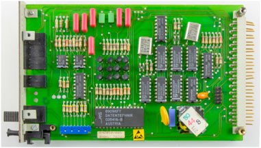
Figure 1. A printed circuit board. ⓒ raimond spekking/CC BY-sa 4.0 (via wikimedia commons).
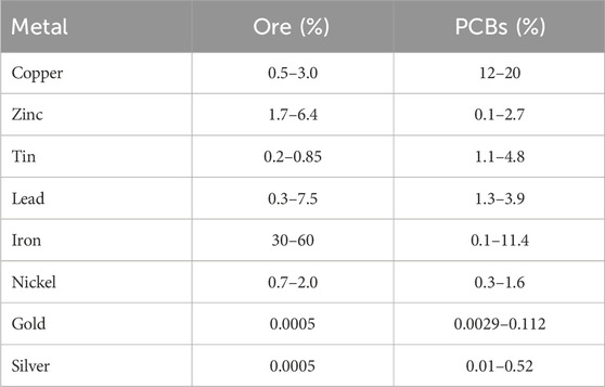
Table 1. Metal content in ores and PCBs (Printed Circuit Boards). Data from (Bizzo et al., 2014).
Several industries already process WPCBs; (Kaya, 2019); includes some commercial examples as follows:
• Müller-Guttenbrunn Group (MGG), Austria: Non-ferrous metals are separated from the e-waste using eddy current separators (ECS) or sieving for pure metal concentration and finally smelted to recover copper and pure metals. MGG treats 80 Kt of e-waste yearly. MGG recovers approximately 850,000 t of metals with a recovery of 85%. (M.-G. Group, 2024).
• Alberich, Spain: Waste from Electrical and Electronic Equipment (WEEE) is fed into a super pre-chopper and then a ring shredder. Electro-magnetic band magnets are used to remove ferrous metals, after which a two-stage eddy current separator is used to remove nonferrous metals. The output fractions comprise various nonferrous metals, ferrous metals, dust, refining materials like copper, and organic fractions containing plastics and resin. (Alberich, 2024).
• Aurubis, Germany: Copper and electric/electronic scrap and residues are first crushed and then processed via pyrolysis in the Lünen or Hamburg facilities. According to their webpage (Aurubis, 2024) “Copper, nickel, tin, lead, and the precious metals contained in the raw materials are enriched in an alloy with a copper content of about 80%”. Then, copper is further enriched to 95%. Tin and lead are processed into an alloy and finally refined in copper cathodes until 99% purity. Gold and silver are enriched in the anode.
• Mint Innovation, New Zealand: Waste material is milled to a sand-like consistency and mixed with a proprietary leaching solution to dissolve the metals. The mixture is then passed through a filter press to separate solids from liquids. Electrolysis is used to recover the copper from the liquid phase. Gold, silver and palladium are left in the solid residue cake. A second leaching step dissolves the former minerals. Microbes are added to the liquid phase to selectively collect the gold. The gold-coated microbes are filtered out, forming a paste that is calcined and refined into gold (M. Innovation, 2024a; M. Innovation, 2024b).
The processing of WPCBs has also attracted academic research. The use of mechanical scraping is suggested in (Li and Xu, 2010), combined with corona electrostatics as an environmentally friendly technology used to recover resources and products from WPCB. Froth flotation is discussed in (Vidyadhar and Das, 2013) as a promising technology to reject plastics from the pulverized product. The pulverized PCB powder was investigated by varying the operating variables such as pulp density, frother dosage, air flow rate, and impeller speed in froth flotation. Varying these parameters, they found optimum values of variables for maximizing the yield and grade. The authors also established that the removal of substantial plastics from the pulp was achievable with a residence time of 1 min, which resulted in a metal yield of 76% and recovery of 95%. The separation of species through air classification was analyzed in (Eswaraiah et al., 2008). This method is a relatively clean mechanical separation method that can achieve a reasonable separation of metals and plastics from WPCBs. In (Yokoyama and Iji, 1997) an automatic part removal apparatus is described, which successfully removes through-hole devices as well as surface mounted devices from WPCBs with almost no damage to the electrical components. This method heats PCBs above the melting point of solder (about 180°C) and removes components through impact, shear, and vibration. Results showed final solder removal to total 96% w/w.
Despite the increasing number of publications on WPCBs recycling, and the inferred positive economic potential (from the company webpages), process systems engineering studies on this topic are scarce. The aim of this paper is to discuss the capabilities of optimization-based conceptual design to tackle the recovery of metals from e-waste problem and to demonstrate these capabilities with a basic case study.
This paper is organized as follows: Section 2 discusses the steps involved in processing WPCBs; Section 3 covers the development of superstructures and their mathematical modeling to find optimal WPCBs processing pathways. The section ends by describing how to use commercial simulators to obtain data required for the mentioned optimization step. Finally, in Section 4 we present the implementation and solution of a problem for finding the pathway that maximizes the revenues.
2 Processing of WPCB’s
PCBs generally contain 40% of metallic components and 60% of non-metallic components; the latter is roughly equally divided between organic resins and ceramics (Khaliq et al., 2014). The objective of recycling is to recover the metallic components that are more valuable. As reported in (Priya and Hait, 2018) PCBs have a large variation in terms of their elemental metal composition. Establishing the best sequence for extraction and separation of individual metallic components is the main process design objective. The following steps are used to recover the minerals from WPCBs.
1. Disassembly of the PCB from the equipment: This involves recovering the PCB from the electronic device. The operation can be achieved by either using manual labor or automatic crushing techniques. Manual labor is, in principle, more expensive but allows for reusing some of the still functioning parts. Automatic crushing techniques are not generally used as they result in higher losses of pure metals in the form of dust, but may be adequate for smaller electronics.
2. Disassembly of the electronic components (ECs) from the PCB: ECs are connected to the PCB by soldering, riveting/bolting, foaming, or painting. PCBs are designed for durability of 30 years (Wileman et al., 2021), but by the end of their use, most ECs have been used for less than 2.2 years (Chen et al., 2013a). Hence, many of the ECs in WPCBs are still useable and can be recycled this way. The bare WPCB, together with the ECs that, for some reason, are not recycled or damaged, are the ones processed for metal recovery. This disassembly step requires desoldering and dislodging of the ECs from the matrix. Desoldering can be carried out by thermal or chemical treatments. Chemical treatments are associated with waste acids, alkaline liquid, and sludge which causes secondary pollution. Hence, thermal treatment processes are preferred. Contributions discussing different desoldering technologies can be found in (Duan et al., 2011) (general recommendations for temperature setting), as well as air heated desoldering (Wang et al., 2016) (use of industrial waste heat (Chen et al., 2013b)) and the use of ionic liquids in desoldering (Zeng et al., 2013). Commercial PCB desoldering units can also be found in the market (Expert, 2024). Dislodging of the ECs from the WPCB and recovery of the solder can be done by (mechanical) sweeping or centrifugal separation methods (Kaya, 2019).3. Size reduction: Once the working ECs have been separated from the PCBs, efficient recovery of metals from the bare WPCB requires size reduction techniques aimed at improving the efficiency of downstream extraction steps. Size reduction techniques can be divided into two categories: 1) Dry size reduction and 2) Wet size reduction. Dry size reduction involves the use of shredders, blade or hammer mill pulverizers, or granulators. Literature specific to size reduction of ECs in WPCBs can be found in (Pan et al., 2007; Gao et al., 2008; Lee et al., 2012; Wang and Xu, 2015; Kaya, 2019). Wet size reduction is done with similar equipment but with the addition of a water inlet. The particles resulting from size reduction are now in the form of a slurry that is carried out through sieve tubes. The benefits of using this technique include avoiding dust and excessive temperature during crushing. However, this produces a large amount of wastewater containing particulate matter that requires careful treatment prior to disposal. References for these operations can be found in (Pan et al., 2007; Duan et al., 2009; Kaya, 2019).
Size reduction operations also have to be performed in tandem to reach the particle size desired for downstream processes. According to (Wang and Xu, 2015), 96%–99% metals are liberated when the size of the WPCB is approximately 5 mm; and most are liberated when the size is 2–5 mm. According to (Lee et al., 2012), reducing it further diminishes its returns. Shredding techniques reduce the size to a minimum of 3 mm; pulverized WPCB in the order of 1 mm in size are generally mentioned in the references described in the Introduction.
4. Sorting and separation: After size reduction, bare WPCBs are processed to separate the non-metallic fraction (NMF) from the metallic fraction (MF) as well as the metals themselves. Separation can be accomplished by a combination of the following means.
(a) Gravity Separation: This is based on the specific gravity differences between the metallic and non-metallic (resin and fiber) fractions and a fluid (air, water). The Concentration Criterion (CC) defined as measures the ease of the separation; if CC > 2.5 then separation is easy. References for CC based on material and fluid density can be found in (Sarvar et al., 2015).
(b) Magnetic Separation: This operation separates magnetic from non-magnetic particles, and can be done in several tandems by using magnetic fields of different strengths.
(c) Electrostatic Separation: separates conductive and nonconductive/nonferrous materials according to their conductivity/resistivity differences (Kaya, 2019). The main types of electrostatic separators are Corona electrostatic separators and eddy current separators (ECS). These are applied only after removal of ferrous material.
(d) Froth Flotation: This operation separates hydrophobic from hydrophilic materials. It basically removes the hydrophobic plastics from the crushed, bare WPCB from the metallic particles. The problem with froth flotation process is that the crushed product should be of size 1 mm for effective separation. Vidyadhar indicates the crushed product of 1 mm size has a recovery of 97.2% but the grade of metal is merely 31.8% (Vidyadhar and Das, 2013).
(e) Supergravity: This operation combines a heating furnace with a centrifuge. It requires prior removal of the non-metallic fraction of the WPCBs, and it is used to separate the tin and alloy solder and copper and zinc from the rest of the metallic fraction (Meng et al., 2018). Hence this step removes the need to desolder the WPCB beforehand. The principle of this method is to create a supergravity field using a centrifugal apparatus with a heating furnace and counterweight fixed to a motor. Supergravity separation is accomplished in two different tanks, a separation tank and a counterweight tank which keeps the apparatus stable. The melting point of lead and tin is 410 C whereas for copper it is 1300 C. Once the non-metallic fraction is removed using one of the previous methods, a heated centrifugal apparatus can be used to remove the lead and tin alloy (solder) in 5 min. Then the WPCB is reheated to 650–1300 C for 30 min before the centrifugal device is rotated. After 10 min the device is shut down, and the blister Cu is quenched in water. Refined Cu can be obtained by electrolysis and the remaining residue can be extracted using hydrometallurgical processes. Approximately 54.41% lead and 41.94% tin are recovered during the first separation. 93.52% copper is recovered and 90.96% zinc is recovered after the reheating stage (Wang et al., 2016).
(f) Hydrometallurgy (leaching): This operation involves the use of solvents to selectively dissolve and extract the metals as cations. Reagents including sulfuric acid, hydrogen peroxide, thiosulfate and aqua regia are used in tandem to exploit differences in solubility of the different metallic salts.
5. Electrolysis: This operation is used as a final step to reduce the metallic salts to metal. As it is required by all processing options for WPCBs and incurs the same CAPEX and OPEX costs for each option, we do not include this step in this study.
3 Application of PSE tools to WPCB processing
3.1 Development of superstructures for pathway selection
Given the many possible and interlinked options, identifying the best WPCB processing pathway can be challenging. Superstructure optimization approaches are ideally suited to tackle this problem. Based on a selection of the processing steps described in Section 2 we developed the superstructure shown in Figure 2. At this point, it is worth mentioning that data for modeling these processes are very scarce; the superstructure corresponds to those processing options for which we found data. Other processing options, once available, could also be added to the superstructure.

Figure 2. Superstructure of processing options.
The rationale is as follows: the superstructure is divided into five stages that coincide with the processing steps discussed above. The processing pathway contains one (or more) of the alternative options in each stage. Based on the practices and recommendations described in Section 2, we consider only manual disassembly of the PCB from the equipment and automatic desoldering of the electronic components. While other options could be included, three streams are obtained after these two operations in any case. The first contains the solder Sn/Pb, the second the electronic components, and the third comprises bare WPCBs from where metals are to be recovered. The latter must be reduced in size for efficient recovery of metals. Based on data availability, a sequence consisting of shredding (which leads to particles between 5 and 20 mm) and pulverization step (leading to particles up to 1 mm) is proposed. This is shown in the upper graphic in Figure 2.
Following these “mandatory” steps, Figure 2 shows several options for the first separation step. The first option is to use air gravity to separate metals and non-metals based on their specific gravity. Non-metals are lighter and, hence, float on the top of the separator, whereas the heavier metals are left in the recovery zone at the bottom. The non-metals are removed from the separator as dust, and the metals are sent to other processes for further recovery. The recovery grade of the non-iron metals is almost complete using this technique. This option has as a drawback the selective loss of iron and copper. To counter this drawback, magnetic/electrostatic separation can be used beforehand to remove the ferromagnetic material. This leads to the second option, in which ferromagnetic materials are separated first by the application of a magnetic force. The stream containing the non-ferrous materials is now subject to air gravity separation, where the remaining metals are separated from the non-metallic dust. A third alternative is to use eddy current separators (ECS) after the magnetic separation. ECS separates metals like Cu, Al, Zn, Au, and Ag from the non-metals.
All these three pathways lead to a mix of non-ferrous metals containing copper, zinc, gold, and silver, which can now be recovered individually. Given the economic importance of copper (and its more developed recycling industry), copper may be selectively recovered first via supergravity separation. Then, the rest of the metals are recovered via a tandem of leaching processes.
We note that supergravity separation has the drawback that some of the gold and silver melt to form alloys with copper, and the rest stay with the remaining metallic residue. While the copper-silver-gold alloys may be treated with electrolysis or other hydrometallurgical processes to further separate them, the fact that valuable gold and silver are split into two streams is not desirable. An alternative is to skip the supergravity separation step and separate the copper also via leaching. Finally, electrolysis processes are applied to recover the metals in their reduced form. This is beyond the scope of this study.
3.2 Mathematical model of the superstructure
The superstructure in Figure 2 can be represented as a network, and the optimal pathway can be found via mathematical programming. Here, we develop the equations required to formulate the optimization problem starting from the stream labeled “Bare WPCBs 1 mm”. These equations are constrained by using the split fraction approach described in (Biegler et al., 1997). We also assume we know all the properties of these streams.
Figure 3 shows the notation to be used. The sorting and separation of the metals stage is further divided into four sub-stages indexed by j; index i denotes alternative technologies at each substage j; the index s indicates a stream flowing in or out of technology (i, j), index k denotes the components. Flows are represented by variable f;
Inlet and outlet flows for each technology (i, j) are related through a (known) split fraction αi,j,s,k which can be defined as:
where αi,j,s,k relates the outlet flow for a component k with respect to a key component in the key stream entering technology (i, j).
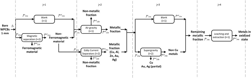
Figure 3. Superstructure of processing options - Notation for mathematical modeling.
The choice of key component and key stream is arbitrary and may change for different components. A reasonable choice is the limiting reactant as the key component and the stream that contains it in the largest amount as the key stream.
All other inlet streams, for example, solvents, can be similarly expressed in terms of the key stream via a (known) split fraction βi,j,s,k:
or in terms of a key component of the key stream:
Both αi,j,s,k and βi,j,s,k are parameters of the problem obtained from literature or from process simulations as explained in the next section.
There are several ways to derive the equations that represent the possible connections between the technologies. A simple one is to first consider the connections as mixer/splitters and write the mass balances for them:
Then, define a binary variable yij for each technology (i, j) such that yij = 1 if the technology is in the optimal pathway and yij = 0 otherwise. Binary variables yij and the corresponding continuous variables are related through big-M constraints:
Finally, to guarantee that at least one technology is selected at each stage, we write
In this study, we choose product revenues and operating costs to be optimized, with the objective function expressed as:
Here, OPEXi,j is a decision variable that depends on the flowrate to unit (i, j) and can be expressed as a function of the flowrate of the key stream a to the unit. This is given by:
and Revenuesk are the revenues obtained from selling the individual metals.
Big-M constraints are used to account for OPEXi,j only if unit (i, j) is selected for the optimal pathway.
We also note that while CAPEX terms can easily be included in this objective function, they were omitted in this study due to a lack of minimum reliable data. The resulting optimization problem is written as:
3.3 Process simulation to define parameters in the optimization model
Eqs 4, 6 require knowledge of the split fractions αi,j,s,k and βi,j,s,k, which can be obtained from literature sources or, better yet, from process simulations. To exemplify this, we will describe the steps to find αi,j,s,k and βi,j,s,k for a hydrometallurgy process representative of sub-stage j = 4 in Figure 3.
As mentioned above, hydrometallurgy processes require selective dissolution and precipitation of the metals, which is generally done in tandems of batch reactions. We simulated part of a hydrometallurgy process used in the recovery of copper, zinc, nickel, gold, and silver.
The process is schematized in Figure 4. The first step (reactor R1) is a leaching step where a solvent composed of 2 M sulfuric acid and 0.2 M hydrogen peroxide (stream Solvent 1) is used as the oxidizing agent for the metals remaining in stream
The slurry obtained after the reaction contains the metals that do not dissolve in the previous mixture, such as silver, gold, and palladium, in the solid phase. A horizontal filter is added to separate the liquid from the solid phase. The liquid phase (Solution dissolved metals 1) is further treated until ready for electrolysis to obtain pure metals. The solid residue (Metallic residue 1) is sent to the second reaction step (reactor R2) where a 0.2M Ammonium thiosulfate, 0.02M copper sulfate, and 0.4M ammonia leaching solution (Solvent 2) dissolves silver and gold:
After this step, the solution (Solution dissolved metals 2) contains a mixture of gold and silver thiosulfate, while the solid residue (Metallic residue 2) may contain palladium (if present in the WPCB). If recovery of palladium is desired, the previous solid residue can be further solubilized by dissolving it in aqua regia:
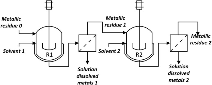
Figure 4. Common schematic of hydrometallurgical process.
This particular step is not considered in this study, as only trace amounts of palladium are generally present.
The tandem of reactors and filters can be implemented in a commercial simulator. The choice of model depends on the available data, for example, conversion rates vs. kinetic data. By comparing Figures 3, 4, it is clear that stream Metallic residue 0 should be chosen as the key inlet stream for stage j = 4,
3.4 Completing the split fraction models
We now complete the models discussed above with process data, starting with the WPCB stream with the composition shown in Table 2.
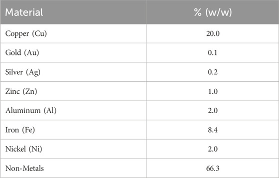
Table 2. WPCB composition at the inlet of the superstructure in Figure 2 (composition of stream x0).
For magnetic separation, air gravity, eddy current separator, and supergravity, αi,j,s,k values are taken from literature and are referred to as key components. For all these cases a proper key component has the same component in the key stream. For example, as shown in (Hanafi et al., 2012), the magnetic separator splits 87.9% of the incoming iron and nickel into the ferromagnetic material stream. Thus,α2,1,2,Fe = 0.879, α2,1,1,Fe = 0.171 and Eq. (4) are written as:
The complete set of αi,j,s,k values used in the optimization problem is shown in Table 3.
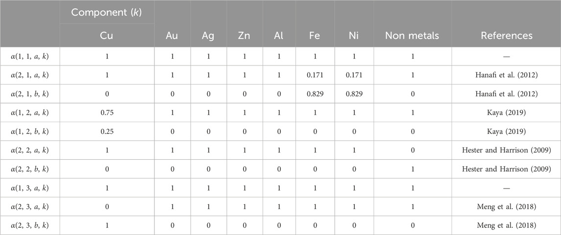
Table 3. Split fractions for magnetic separation, air gravity, eddy current separator and supergravity.
For the hydrometallurgical extraction step, we generate the data for α and β from Aspen Plus simulations. As mentioned above, Solvent 1 is a 2 M H2SO4 and 0.2 M H2O2 solution in water. Using the e-NRTL package to properly account for acid dissociation and considering a requirement of 36.5 L solvent/lb WPCB, the values shown in Table 4 are obtained for β1,4,b,k. α1,4,a,k (Solution dissolved metals 1) are also obtained from the simulations, assuming the values in Table 5 for the reactors’ fractional conversions and filter specifications. Notice that, in this case, we define β1,4,b,k (components for the solvent) in terms of the total flow of the inlet stream
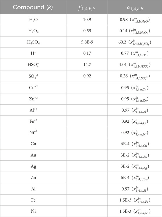
Table 4. Split fractions for hydrometallurgy.
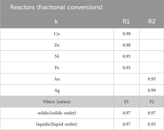
Table 5. Fractional conversion and separation (filter) data used in Aspen simulations. Data extracted from (Oh et al., 2003): R1 batch reactor at 85°C achieving 98% recovery of copper and zinc after 8 h and 95% recovery of nickel and iron in 12 h; R2 batch reactor achieving 100% recovery of silver in 24 hs, and 95% recovery of gold in 48 hs.
Note that in the previous derivation, we have assumed constant values for the split fractions αi,j,s,k and βi,j,s,k. This assumption stems from the currently available data. However, non-constant αi,j,s,k and βi,j,s,k values that vary with processing conditions could be derived if rigorous kinetic or separation data are available.
4 Optimization implementation and results
Based on the modeling steps in the previous section, we now present the implementation and solution of an optimization model for an e-waste recycling process with a capacity of 8,000 lbs/day of WPCBs. The mandatory processes start with desoldering the electronic components and removal of Pb and Sn. The remaining bare WPCBs need first to be shredded. For OPEX calculations, we assume that a four-shaft shredder with a total power requirement of 80 kW crushes the material into approximately 5 mm pieces. A pulverization step to crush the feed to 1 mm pieces is considered after the shredder. For OPEX calculations, a power requirement of 110 kW is assumed for this last crusher. Consequently, 4,000 lbs/day of 1 mm bare WPCB makes up the feed for the pathway operations presented in Figure 3.
Using the power requirements in Table 6 and the solvent costs in Table 7 to calculate the OPEX, and the prices in Table 8 to calculate the revenues, an MILP problem formulation (with 798 variables) was implemented in GAMS (v37.1) to choose the process pathway that leads to maximum profit. The CPLEX (v20.1.0.1) solver in GAMS provides an efficient solution to this problem within only 0.1 CPUs on a MacBook Pro with an 8-core CPU and Apple M2 chip. We note that if non-constant values for αi,j,s,k and βi,j,s,k are considered, the problem will become a Mixed Integer Non-Linear Program (MINLP). In that case, piecewise linear approximations could be derived to preserve the linearity of the problem. Otherwise, a MINLP solver such as BARON (Sahinidis, 1996) or Gurobi (Gurobi Optimization and LLC, 2023) could be used to solve the MINLP.
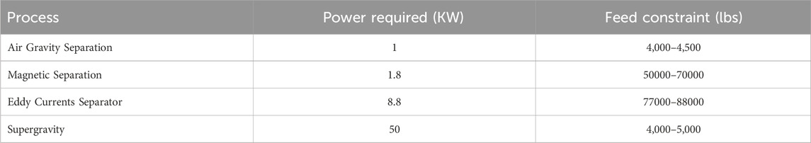
Table 6. Power Requirements assumed for calculation of OPEX.

Table 7. Solvent costs assumed for the calculation of OPEX.
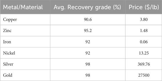
Table 8. Average recovery grade of each metal with its price.
The optimum (largest profit) pathway considers magnetic separation followed by air gravity, supergravity and hydrometallurgy; this is shown in Figure 5. We also investigated the profits of the other possible pathways. The resulting profits for each possible process pathway are shown in Table 9, with the optimal pathway shown in the last row.
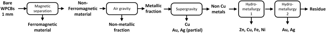
Figure 5. Maximum profit pathway for the WPCB recycling process.
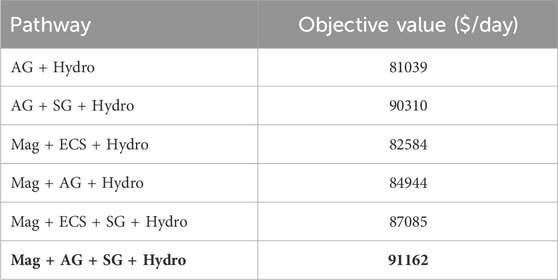
Table 9. Objective function values for different processing pathways. Mag = Magnetic separation, AG = Air gravity separation, ECS = Eddy currents separator, SG = Supergravity separation, Hydro = Hydrometallurgy operation. The optimal solution is highlighted in bold text.
From Table 10, we see that the recovery of metals is similar for any chosen pathway. The key differences in OPEX are due to power requirements of individual processes, as shown in Table 6 as well as the operating requirements for hydrometallurgy. Each pathway requires hydrometallurgical processing, but solvent requirements may be considerably different, as shown in Table 11.
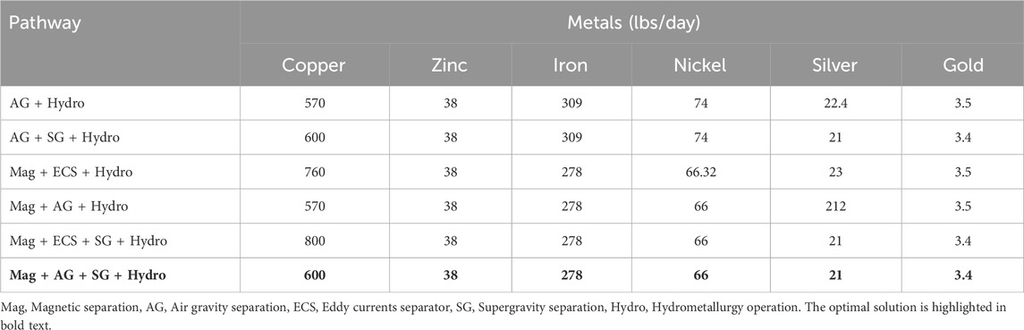
Table 10. Recovery of metals using different pathways.
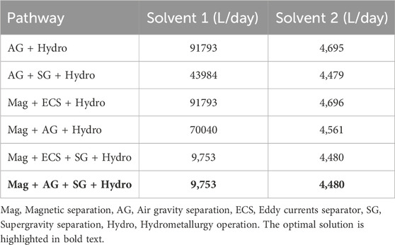
Table 11. Solvent required for each individual pathway.
We note that the optimal pathway shows that supergravity is an effective way to recover copper and other precious metals. This can also be seen in the second and fifth competing pathways, where supergravity separation (in the second and fifth) provides a significant improvement over pathways without these steps. Similarly, we note that magnetic separation is favored as iron and nickel are removed earlier in the flowsheet.
Other features of the optimal pathway include:
• Magnetic separation followed by air gravity separation ensures maximum recovery of iron and nickel, thus eliminating the cost of their electrolysis.
• The air gravity method leads to a loss of approximately 25% Cu, but other factors, such as less solvent and no electrolysis to separate Fe and Ni, make it the best option after magnetic separation.
• Using supergravity separation ensures a much lower feed for hydrometallurgy treatment, as we have already recovered Fe and Ni from magnetic separation and Cu from supergravity.
5 Conclusion
Printed circuit boards (PCBs) are significant consumers of mineral resources, and are major producers of e-waste, which often contains higher mineral contents than in mineral ores. Recycling from e-waste is therefore an essential topic to limit disposal problems and to maintain sustainable mineral sources. While e-waste recycling processes have seen considerable research and commercialization, there are few research studies that apply process systems engineering methods to synthesize optimal e-waste recycling systems. This paper deals with the development and demonstration of an optimization-based strategy for the conceptual design of metals recovery from e-waste. The paper first introduces the e-waste recycling problem, provides a brief summary of current industrial practice, and summarizes several academic studies on e-waste recycling. This background illustrates qualitative performance trade-offs in various e-waste processing steps, which motivate the development of optimization models. These models are further informed by discussing the major steps involved in processing waste PCBs (WPCBs).
To formalize the conceptual design problem, these processing steps are organized into a superstructure of flowsheeting options, which are quantified through the development of mathematical models, constraints and decision variables that lead to optimization formulations. These models are populated with process data drawn from the literature as well as from process simulations. The resulting models are formulated as mixed integer linear programs (MILPs), and the study develops and presents an MILP case study that determines an optimal process within a basic superstructure of process options. Solution of the MILP requires negligible computation (
Our systematic conceptual design approach and optimization results also highlight a number of directions for future research. An important next step will be to develop and include more detailed process models that provide improved accuracy in process performance. These models will also allow additional decision variables and specifications for the processing units, in order to provide more flexible and more efficient operation. Also needed is the inclusion of accurate capital cost models for advanced recovery processes. Finally, our goal is to expand the scope of superstructure optimization models to include front-end size reduction processes, back-end electrolysis operations, and advanced process technologies overall.
Data availability statement
The original contributions presented in the study are included in the article/Supplementary material, further inquiries can be directed to the corresponding author.
Author contributions
SP: Data curation, Writing–original draft, Investigation, Formal Analysis. AT: Writing–original draft, Writing–review and editing, Supervision, Resources, Project administration, Methodology, Funding acquisition, Formal Analysis, Conceptualization. LB: Writing–original draft, Writing–review and editing, Supervision, Resources, Project administration, Methodology, Funding acquisition, Formal Analysis, Conceptualization.
Funding
The author(s) declare that no financial support was received for the research, authorship, and/or publication of this article.
Acknowledgments
The authors gratefully acknowledge funding from the Center for Advanced Process Decision-making at Carnegie Mellon University and AI. Torres start up package.
Conflict of interest
The authors declare that the research was conducted in the absence of any commercial or financial relationships that could be construed as a potential conflict of interest.
Publisher’s note
All claims expressed in this article are solely those of the authors and do not necessarily represent those of their affiliated organizations, or those of the publisher, the editors and the reviewers. Any product that may be evaluated in this article, or claim that may be made by its manufacturer, is not guaranteed or endorsed by the publisher.
References
Alberich (2024). 120 años al servicio del reciclaje, especialistas en reciclar, recuperar y reutilizar. Available at: https://www.alberich.net/.
Aurubis (2024). Recycling technology. Available at: https://www.aurubis.com/en/products/recycling/technology.
Baldé, C. P., D’Angelo, E., Luda, V., Deubzer, O., and Kuehr, R. (2022) Global transboundary e-waste flows monitor 2022. Bonn, Germany: United Nations Institute for Training and Research unitar.
Biegler, L. T., Grossmann, I. E., and Westerberg, A. W. (1997) Systematic methods for process design. Upper Saddle River, NJ: Prentice-Hall.
Bizzo, W., Figueiredo, R., and Andrade, V. (2014). Characterization of printed circuit boards for metal and energy recovery after milling and mechanical separation. Materials 73390, 4555–4566. doi:10.3390/ma7064555
Chen, M.-J., Wang, J.-B., Chen, H.-Y., Oladele, A. O., Zhang, M.-X., Zang, H.-B., et al. (2013a). Electronic waste disassembly with industrial waste heat. Environ. Sci. Technol. 47 (21), 12409–12416. doi:10.1021/es402102t
Chen, M.-J., Wang, J.-B., Chen, H.-Y., Oladele, A. O., Zhang, M.-X., Zang, H.-B., et al. (2013b). Electronic waste disassembly with industrial waste heat. Environ. Sci. Technol. 47 (21), 12409–12416. doi:10.1021/es402102t
Duan, C., Wen, X., Shi, C., Zhao, Y., Wen, B., and He, Y. (2009). Recovery of metals from waste printed circuit boards by a mechanical method using a water medium. J. Hazard. Mater. 166, 478–482. doi:10.1016/j.jhazmat.2008.11.060
Duan, H., Hou, K., Li, J., and Zhu, X. (2011). Examining the technology acceptance for dismantling of waste printed circuit boards in light of recycling and environmental concerns. J. Environ. Manag. 92, 392–399. doi:10.1016/j.jenvman.2010.10.057
Eswaraiah, C., Kavitha, T., Shilapuram, V., and Narayanan, S. (2008). Classification of metals and plastics from printed circuit boards (pcb) using air classifier. Chem. Eng. Process. Process Intensif. 47, 565–576. doi:10.1016/j.cep.2006.11.010
Expert, E. (2024). Jiangxi mingxinmetallurgy equipment co. ltd. Available at: https://www.environmental-expert.com/products/model-mx-300-pcb-electric-components-dismantling-machine-623821.
Gao, P., Xiang, D., Yang, J., Cheng, Y., Duan, G., and Ding, X. (2008). Optimization of pcb disassembly heating parameters based on genetic algorithm. Mod. Manuf. Eng. 8, 92–95.
Gurobi Optimization, LLC (2023) Gurobi optimizer reference manual. Beaverton, Oregon: Gurobi Optimization, LLC.
Hanafi, J., Jobiliong, E., Christiani, A., Soenarta, D. C., Kurniawan, J., and Irawan, J. (2012). Material recovery and characterization of pcb from electronic waste. Procedia-Social Behav. Sci. 57, 331–338. doi:10.1016/j.sbspro.2012.09.1194
Kaya, M. (2019) Industrial-scale E-waste/WPCB recycling lines. Cham: Springer International Publishing, 177–209.
Khaliq, A., Rhamdhani, M. A., Brooks, G., and Masood, S. (2014). Metal extraction processes for electronic waste and existing industrial routes: a review and australian perspective. Resources 3 (1), 152–179. doi:10.3390/resources3010152
Lee, J., Kim, Y.-J., and Lee, J.-C. (2012). Disassembly and physical separation of electric/electronic components layered in printed circuit boards (pcb). J. Hazard. Mater. 241–242, 387–394. doi:10.1016/j.jhazmat.2012.09.053
Li, J., and Xu, Z. (2010). Environmental friendly automatic line for recovering metal from waste printed circuit boards. Environ. Sci. Technol. 44 (4), 1418–1423. doi:10.1021/es903242t
Meng, L., Zhong, Y., Wang, Z., Chen, K., Qui, X., Cheng, H., et al. (2018). Supergravity separation for Cu recovery and precious metal concentration from waste printed circuit boards. ACS Sustain. Chem. Eng. 6, 186–192. doi:10.1021/acssuschemeng.7b02204
M.-G. Group (2024). Waste electric and electronic equipment (weee). Available at: https://mgg-recycling.com/recycling-services/waste-electric-and-electronic-equipment-weee/.
M. Innovation (2024a). From trash to treasure. Available at: https://www.mint.bio/what-we-do.
M. Innovation (2024b). Mint the urban mine. Available at: https://www.youtube.com/watch?v=PH4ENXqk5zQ.
Oh, C. J., Lee, S. O., Yang, H. S., Ha, T. J., and Kim, M. J. (2003). Selective leaching of valuable metals from waste printed circuit boards. J. Air and Waste Manag. Assoc. 53 (7), 897–902. doi:10.1080/10473289.2003.10466230
Pan, X., Li, Z., Zhi, H., and Wang, L. (2007)“Method and apparatus of separation for electronic components and solders from printed circuit boards,”Chinese patent; 2007102015321.
Priya, A., and Hait, S. (2018). Comprehensive characterization of printed circuit boards of various end-of-life electrical and electronic equipment for beneficiation investigation. Waste Manag. 75, 103–123. doi:10.1016/j.wasman.2018.02.014
Sahinidis, N. V. (1996). Baron: a general purpose global optimization software package. J. Glob. Optim. 8, 201–205. doi:10.1007/bf00138693
Sarvar, M., Salarirad, M. M., and Shabani, M. A. (2015). Characterization and mechanical separation of metals from computer printed circuit boards (pcbs) based on mineral processing methods. Waste Manag. 45, 246–257. doi:10.1016/j.wasman.2015.06.020
Statista (2024a). Global e-waste - statistics and facts. Available at: https://www.statista.com/topics/3409/electronic-waste-worldwide/#topicOverview.
Statista (2024b). Leading countries based on per capita electronic waste generation in 2019. Available at: https://www-statista-com.cmu.idm.oclc.org/statistics/499945/per-capita-ewaste-generation-worldwide-by-major-country/.
U. N. University (2024). Global e-waste surging: up 21% in 5 years. Available at: https://unu.edu/press-release/global-e-waste-surging-21-5-years.
Vidyadhar, A., and Das, A. (2013). Enrichment implication of froth flotation kinetics in the separation and recovery of metal values from printed circuit boards. Sep. Purif. Technol. 118, 305–312. doi:10.1016/j.seppur.2013.07.027
Wang, J., Guo, J., and Xu, Z. (2016). An environmentally friendly technology of disassembling electronic components from waste printed circuit boards. Waste Manag. 53, 218–224. doi:10.1016/j.wasman.2016.03.036
Wang, J., and Xu, Z. (2015). Disposing and recycling waste printed circuit boards: disconnecting, resource recovery and pollution control. Environ. Sci. Technol. 49, 721–733. doi:10.1021/es504833y
Wileman, A., Perinpanayagam, S., and Aslam, S. (2021). Physics of failure (pof) based lifetime prediction of power electronics at the printed circuit board level. Appl. Sci. 11 (6), 2679. doi:10.3390/app11062679
Yokoyama, S., and Iji, M. (1997). “Recycling of printed wiring boards with mounted electronic parts,” in Proceedings of the 1997 IEEE International Symposium on Electronics and the Environment (ISEE-1997), San Francisco, CA, USA, May, 1997, 109–114.
Keywords: process design, process optimisation, E-waste, superstructure optimization, mineral recovery, process synthesis
Citation: Palav SD, Torres AI and Biegler LT (2024) Systematic conceptual design strategies for the recovery of metals from E-waste. Front. Chem. Eng. 6:1388456. doi: 10.3389/fceng.2024.1388456
Received: 19 February 2024; Accepted: 25 April 2024;
Published: 21 May 2024.
Edited by:
Fengqi You, Cornell University, United StatesReviewed by:
Yuhe Tian, West Virginia University, United StatesKosan Roh, Chungnam National University, Republic of Korea
Copyright © 2024 Palav, Torres and Biegler. This is an open-access article distributed under the terms of the Creative Commons Attribution License (CC BY). The use, distribution or reproduction in other forums is permitted, provided the original author(s) and the copyright owner(s) are credited and that the original publication in this journal is cited, in accordance with accepted academic practice. No use, distribution or reproduction is permitted which does not comply with these terms.
*Correspondence: Ana I. Torres, YWl0b3JyZXNAY211LmVkdQ==