 Zhang Jingchen
 Guo Xiaodong
 Wang Mingxing4
- 1Unconventional Oil and Gas Science and Technology Research Institute, China University of Petroleum (Beijing), Beijing, China
- 2College of Petroleum Engineering, China University of Petroleum (Beijing), Beijing, China
- 3Xinjiang Taiqi Petroleum Technology Co., Ltd., Karamay, Xinjiang, China
- 4Research Institute of Engineering and Technology, Xinjiang Oilfield Company, PetroChina, Karamay, China
- 5CNPC Engineering Technology R&D Company Limited, China
Temporary plugging and fracturing is an important technology for the efficient development of unconventional reservoirs. Due to the diverse physical properties of unconventional reservoirs and the complex stress environment, the evaluation of temporary plugging effect needs to consider the working conditions in the wells, and it also needs to focus on the transport and placement of temporary plugging agent in the near-well fracture region, so it is impossible to predict the effect of temporary plugging and fracturing effectively. In this paper, a numerical simulation study is carried out to investigate the transport and placement of temporary plugging agent in the near-well area, and a finite element model of “wellbore-near-well fracture” is established based on computational fluid dynamics, and numerical simulation and verification of temporary plugging and fracturing are carried out based on the fiber-optic monitoring data of temporary plugging and fracturing in Well A, as well as the optimization of some construction parameters. The results show that: as the volume concentration of temporary plugging agent increases, the temporary plugging effect is weakened and then strengthened, and the temporary plugging agent will enter into the heel cluster in advance when the concentration is small; at the initial stage, the increase in the quality of temporary plugging agent will cause some clusters to form incomplete plugging, but the quality of the plugging agent will not be changed after the quality is greater than 360kg; the temporary plugging effect is mainly reflected in the heel cluster, and the toe cluster is not obvious. This paper forms a set of temporary plugging and fracturing simulation methods based on the actual fiber-optic monitoring data in the field, which provides a reference for the optimization design of the type, particle size and dosage of temporary plugging agent during the temporary plugging construction process.
1 Introduction
Unconventional reservoirs have the tendency to become the main reservoirs in China in the future, but due to their low permeability and high demand for artificial fracturing, conventional fracturing process can only form a single symmetric fracture, which is gradually unable to meet the demand, and temporary plugging fracturing, which is capable of increasing fracture complexity, has become an effective means; at the same time, temporary plugging agent must be used when old wells are repetitively fractured for production enhancement. (Xin et al., 2024). In this context, the application of temporary plugging and fracturing has become more and more widespread, for example, temporary plugging and fracturing or temporary plugging and repeated fracturing of old wells have been carried out in Tahe Oilfield, Anse Oilfield, tight oil reservoirs of Ordos Basin An83 block, Xinjiang Oilfield and Niuhu Sandstone Reservoir, and good results have been achieved, but at present, there are still shortcomings in the construction of temporary plugging and fracturing. (ZHANG, 2018; JIANG et al., 2023; Xuesong et al., 2023).
The lack of effect prediction and optimization methods during the temporary plugging and fracturing construction process has led to the temporary plugging and fracturing construction still relying on on-site experience and taking the change of pressure curves during the construction as the basis of temporary plugging, resulting in the temporary plugging and fracturing construction having poor temporary plugging effect. (LI et al., 2016; XIE et al., 2021; Kai et al., 2023). The design of temporary plugging agent dosage is not reasonable enough, resulting in poor economy of temporary plugging and fracturing construction and poor temporary plugging effect. At present, the influencing factors of temporary plugging construction effect in the construction process are not clear enough, and there is insufficient research on the influence law of single factor, which cannot exclude the influence of other factors and lacks relevant theoretical support. (ZHENG et al., 2010; WU et al., 2016; WANG et al., 2019; Yifan et al., 2023).After investigation, the current research on the prediction of temporary plugging construction effect has limitations, and the amount of relevant data is relatively small. In order to cope with the different geological background and construction environment during each construction, numerical simulation is a better research and prediction method, so most of the research in this direction uses numerical simulation. (WANG, 2016a).
For example, Lv Ruihua et al. simulated the temporary plugging efficiency of temporary plugging ball in the shot hole section, and adopted the DPM method in CFD software to judge the temporary plugging according to whether the particle trajectory passes through the shot hole or not in the simulation results, and the DPM method is simple to calculate and can reflect some of the particle trajectory. The DPM method is simple and can reflect some of the characteristics of the particles, but the particles in the DPM method do not have the actual volume, so the particles must have passed through the shot hole, but there is no guarantee that the temporary plugging ball will remain stable in the shot hole after reaching the shot hole during the actual construction, which is a limitation of the DPM method. (LV et al., 2020). Zheng Chen et al. also used the DPM method of the CFD software to carry out numerical simulation on the transportation of particles of the temporary plugging agent in the rough crack, and investigated the particle diameter, particle volume fraction, particle volume fraction, and particle volume fraction of the temporary plugging agent. However, the limitations of the DPM method still exist. The particles simulated by this method do not have actual volume and cannot form a volumetric plug, so although this method can be used to judge the overall transport trend of the plugging agent particles in the fracture, it cannot determine whether an effective temporary plug is formed in the rough fracture. In addition to the DPM method mentioned above. (Chen et al., 2022). Tian Yingying simulated the transport of plugging agent at the injection hole and near-well fracture area, and used the CFD-DEM coupling method, which can take into account the force interaction between particles, and the particles in the simulation have the real volume, so that the effectiveness of plugging can be judged according to whether the particles form a volumetric blockage, which is a more accurate calculation, but at the same time makes the calculation volume too large, and requires the model to be more precise. However, it also makes the calculation too large, which requires that the geometric scale of the model should not be too large and the number of particles should not be too many. Due to this limitation, Tian simplified the model to the wellbore at the section of the shot hole with a single shot hole and a single microscopic fracture connected to the shot hole without considering the existence of the shot hole aperture. (TIAN, 2019). Qin Hao et al. also simulated the particle transport of the temporary plugging agent by using the coupling method of CFD-DEM, but the study area is limited to the fracture within the plugging area, which is the only area that is considered as a part of the plugging agent. However, the study area is limited to the cracks. (QIN, 2021). Feng Yi also used the CFD-DEM coupling method to simulate the particle transport of temporary plugging agent in the cracks, and the study area is also limited to the cracks, but the special feature of Feng Yi’s study is that the numerical simulation is designed to cooperate with the physical simulation, and the modeling of the crack model in the numerical simulation is based on the results of the sweep of the physical model, which is a more realistic approach but has higher cost and less generalizability. In the CFD simulation of fracturing fluid and proppant transportation. (Yi, 2023). Wang Boxue considered the existence of shot hole channel, but simplified the shot hole channel into a simple flow channel model of “surrounding wall and end face outlet”, which ignored the characteristics of seepage of fluid from the surrounding of the shot hole channel. (WANG, 2016b). It can be seen that different simulation methods have been adopted for the simulation of the temporary plugging agent transport and the prediction of the temporary plugging effect during the temporary plugging and fracturing, and the simplification and improvement have been made according to the characteristics of different simulation methods, but due to the limitations of the different simulation methods, there are still some improvements in the simulation methods. (SUN et al., 2012). Therefore, in order to make up for the shortcomings mentioned above, and to provide a reliable basis for the determination of the parameters and the prediction and judgment of the temporary plugging effect during the temporary plugging construction, a simulation research method that is more convenient to calculate, more in line with the actual situation, and takes into account the characteristics of the shot hole channel has become an urgent problem to be solved. (Li, 2006).
After consideration, compared with the in-fracture region, the shot hole channel and near-well fracture region have a more important position in temporary plugging and fracturing. Therefore, we choose to simulate the temporary plugging agent transportation for this region. To this end, the CFD software Fluent is used to establish a finite element model of the “wellbore-near-well fracture region” on the premise of seepage of fluid around the injection hole, and then combined with the Standard k-ε turbulence model and the Euler model, the two-phase flow simulation method of solid-liquid flow in the plugging fracturing is finally established. (Yong et al., 2023). The solid-liquid two-phase flow simulation method was finally established. As the Euler method has its own limitations, the calculation of Euler method is simple, and the particles in the calculation have the real volume, but it simplifies the solid-phase particles into a continuous fluid, which can not form a volume blockage, so we borrowed the research results of Yamaguchi E and others, and used the formula to determine the volume fraction of the plugging agent particles with different particle sizes that form a volume blockage inside the injection hole to determine the effect of temporary plugging, and used the temporary plugging agent particles of well A to determine the effect of temporary plugging. (Dongfeng et al., 2022). In order to determine the temporary plugging effect, the monitoring data of fiber optic fiber for temporary plugging and fracturing of well A was used as the benchmark to study the effects of temporary plugging agent concentration, quality of temporary plugging agent, and ratio of temporary plugging agent particle size on the temporary plugging effect.
2 Numerical modeling
The Euler model, the porous media module and the Standard k-ε turbulence model are used to simulate solid-liquid two-phase flow in temporary fracture plugging. The Euler model is used to simulate multiphase flow and granular flow; the porous media module is used to simulate seepage in the near-well fractures and pores, this makes it possible to take into account the seepage of fluid around the perforation depth; and the turbulence of the fracturing fluid is controlled by the Standard k-ε turbulence model.
2.1 The euler model
The Euler model allows for more complex simulations than other multiphase flow models and is more stable in its calculations. It is dominated by the volume fraction equation, the conservation equation.
2.1.1 The volume fraction equation
The q-phase volume fraction Vq is calculated as:
where αq is determined by the following equation:
2.1.2 The conservation equation
(1) Conservation of mass equation
The conservation of mass equation for q-phase is calculated as:
In the equation,
(2) Conservation of momentum equation
The conservation of momentum equation for q-phase is calculated as:
In the equation,
2.2 The porous media module
The porous media module is a computational model for simulating the state of seepage, which is mainly controlled by the momentum equation. (QIN, 2021).
The momentum equation is calculated as:
In the equation, Si --- the source term of momentum in the i-direction.
|v|--- the magnitude of the velocity.
D,C---the prescribed matrix.
The mobility of porous media is also influenced by the particle size of the filled particles (Yi, 2023), with the target block, for example, dominated by medium conglomerate particles with a particle diameter of 8–32 mm as a reference (WANG, 2016b).
2.3 The Standard k-ε turbulence model
The Standard k-ε turbulence model is mainly controlled by the transport equations and other constants.
2.3.1 The transport equations
In the equation, k --- turbulent kinetic energy.
Ε --- dissipation rate.
Gk --- turbulent kinetic energy, generated by the mean velocity gradient.
Gb --- turbulent kinetic energy, generated by buoyancy.
YM --- contribution of pulsating expansion to the total dissipation rate in compressible turbulent flows.
C1ε, C2ε --- constants.
σε, σk --- turbulent Prandtl number.
2.3.2 Turbulent viscosity models
In the equation, Cμ---constants.
Common values for the constants in the above equations are C1ε = 1.44, C2ε = 1.92, Cμ = 0.09, σε = 1.3, σk = 1.0.
2.4 “Wellbore-fracture” model
In other previous CFD proppant simulation studies, the injection depth is often simplified to a simple flow channel model of surrounding wall + end outlet, ignoring the characteristics of seepage outflow around the part of the injection depth. In order to optimize the simulation study method, the wellbore-near-well fracture area model was established by using the porous medium model in CFD software Fluent.
The wellbore-near-well fracture model consists of two models: the wellbore and the near-well fracture region, and the two separate calculations are connected by exporting the Profile file. Because the overall shape of the near-well fracture network formed by the injection hole is similar to a fan, the near-well fracture region model is simplified to an annulus with an outer diameter of 1 m and a thickness of 0.5 m, which is close to the outer wall of the wellbore; in order to solve the problem of ignoring the seepage of fluid around the injection depth in the previous simulation studies, the near-well fracture region model is divided into two parts: the injection depth and the porous medium, with the tubular flow in the injection depth and the simulated porosity and near-well fracture region model in the porous medium. The seepage in the porous medium and the near-well fracture is modeled. The modeling is shown in Figure 1.
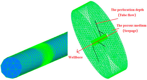
Figure 1. Well model and Near-wellbore fracture zone model.
The majority of the computational domain is meshed using unstructured grids, with a total of 107,260 grids for the near-well fracture region model and a median grid mass Skewness = 0.33; 475,221 grids for the wellbore model and a median grid mass Skewness = 0.3; the grid mass is good.
2.5 Basic parameters of calculation
This calculation takes the temporary plugging and fracturing of Section 5 of well A as an example, with a well diameter of 139.7mm, a shot hole diameter of 10.2mm, a well section length of 133m, a total of 6 clusters, an average discharge rate of 0.853 m³/min, a temporary plugging agent density of 1250 kg/m³, and three types of temporary plugging agent particle sizes including 3, 5–10 mm and 20/60 mesh. Specific well conditions are shown in Table 1.
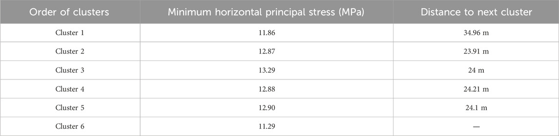
Table 1. Specific well condition of Section 5 of well A
According to the field construction data, the temporary plugging agent injection time is 300s, and the calculated time step (Time Step) is set to 1s, with 20 iterations per time step.
2.6 CFD model validation
Model validation based on fiber-optic monitoring data of temporarily plugged fracturing section 5 of well A. The basic steps are.
(1) Fine tuning with export parameters to replicate the distribution of fluid intake in each cluster before temporary plugging and fracturing.
(2) Determine the plug formation criteria for the plug fracturing simulation.
(3) Comparison of fibre-optic monitoring data with simulation results for verification.
The reason for step (1) is that the formation pressure in the near-well fracture area will change after the perforation, so the main reason is to fine-tune the pressure at the exit (perforation) to reproduce the distribution of fluid intake in each cluster before temporary plugging, so as to determine the actual pressure in the vicinity of each cluster after the perforation, so as to improve the realistic reliability of the subsequent simulation.
2.6.1 Reproduction of fluid intake before temporary plugging
The reproduction of the distribution of the intake volume of each cluster before temporary plugging is shown in Figure 5. The overall distribution trend of the intake volume of each cluster obtained from the simulation is similar to the actual situation, and the average percentage difference is 14.44%, which is less than 15%, so the reproduction situation is good.
Based on the fibre-optic monitoring data and simulation results, Cluster 1 and Cluster 6 were found to be the main clusters feeding the fluid, with Cluster 6 being particularly important, with the amount of fluid feeding Cluster 1 starting to decrease later.
2.6.2 Perforation depth plugging criteria
Due to the principle of CFD software calculations, it is not possible to form a real blockage and therefore a manual analysis based on the calculation results is required to determine the provisional blockage results. According to (TIAN, 2019), the majority of blockages formed by particles in circular flow channels are “bridging” blockages, and chemical blockages are more difficult to form. Therefore, the volume fraction can be used to determine whether a successful plug is formed at the perforation depth, as determined by Equations 1.9)–(1.14), (SUN et al., 2012),
In the equation, dp ---- particle diameter.
D ---- diameter of the flow channel.
ζ ---- volume fraction.
After N and Nc are obtained, N ≥ Nc needs to be satisfied in order to indicate that the particles are causing flow channel blockage. According to the calculation of temporary plugging agent particle size 3mm, 5–10mm, 20/60 mesh, and perforation depth diameter 10.2mm, if temporary plugging needs to be formed at the perforation depth, the volume concentration of the three temporary plugging agents within the perforation depth need to reach ζ3mm ≥ 0.414%, ζ5–10mm ≥ 0.00716% and ζ20/60 mesh ≥ 51.7% respectively.
2.6.3 Validation of temporary plugging simulation results
Add 140 kg of 3 mm temporary plugging agent, 40 kg of 5–10 mm temporary plugging agent and 180 kg of 20–60 mesh powder temporary plugging agent, as for construction. Based on the amount of sand entering each cluster, it can be seen that the temporary plugging agent mainly entered Cluster 1 and Cluster 6, which is consistent with the distribution of the temporary plugging forward fluid, and the temporary plugging agent mainly entered the dominant cluster with the fluid. Therefore, the situation is mainly shown at the near-well fracture area in clusters 1 and 6 (Figure 2), with the middle face of the near-well fracture area containing the most sand-prone perforation 1 and perforation 3, as shown in Figures 3, 4.
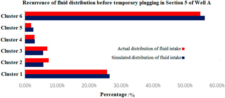
Figure 2. Recurrence of fluid distribution before temporary plugging in Section 5 of Well A.
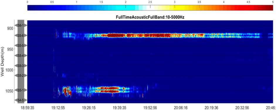
Figure 3. Optical fiber monitoring results before temporary plugging in Section 5 of Well A (fluid intake).
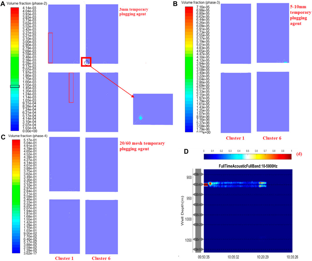
Figure 4. (A) 3 mm volume fraction of temporary plugging agent in the first and sixth clusters; (B) 5–10 mm volume fraction of temporary plugging agent in the first and sixth clusters; (C) Volume fraction of 20/60 mesh temporary plugging agent in the first and sixth clusters; (D) Optical fiber monitoring data of temporary plugging fracturing in Section 5 of Well A (fluid intake).
Based on (a), (b) and (c) in Figure 4, it can be seen that none of the three particle size temporary plugging agents formed a plug within cluster 1; however, the 3 mm particle size temporary plugging agent formed an aggregation of 0.145%–0.155% by volume in some areas within the perforation depth of cluster 6, creating an incomplete plug.
According to (d) in Figure 4, it can be seen that the amount of incoming fluid in Cluster 6 gradually decreases when the fluid is injected again after the temporary blockage, but does not disappear completely, and it can be assumed that the temporary blocking agent has formed an incomplete blockage in Cluster 6.
As a result, the results of the simulations and the results of the temporary plugging and fracturing fibre monitoring agree with each other, proving the reliability of the model.
3 Optimisation of temporary plugging construction parameters
On the basis of proving the reliability of the model, the temporary plugging effect obtained from the monitoring of the temporary plugging and fracturing fibre optics in Section 5 of well A is taken as the benchmark, and three construction parameters, namely, the concentration of temporary plugging agent, the mass of temporary plugging agent and the ratio of temporary plugging agent particle size, are simulated in the form of orthogonal experiments, and the calculation results are compared with the temporary plugging effect in Section 5 of well A to achieve the effect of parameter optimisation, so as to answer the practical question of “how much concentration, how much quantity and what particle size to add” for the temporary plugging and fracturing construction site.
3.1 Temporary plugging agent concentration
The volume fraction of the temporary plugging agent at the time of temporary plugging construction in Section 5 of well A was 1.56%, and based on this, simulations were carried out for three other groups of temporary plugging agent injection concentrations, which were 0.78%, 3.12% and 6.24% by volume. According to the calculation results, the temporary plugging agent mainly enters Cluster 5 and Cluster 6 when the temporary plugging agent concentration is 0.78%; when the temporary plugging agent concentration is 1.56% and 3.12%, the temporary plugging agent mainly enters Cluster 1 and Cluster 6; when the temporary plugging agent concentration is 6.24%, the temporary plugging agent mainly enters Cluster 6.
3.1.1 Comparison of simulation results
The calculated results of the four groups of temporary plugging agent concentrations were compared and analysed, and the results are shown in Figures 5, 6.
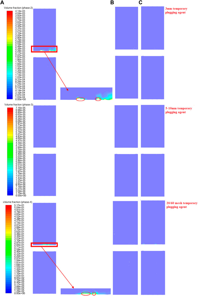
Figure 5. (A) Temporary blocking situation of the fifth cluster when the concentration of temporary plugging agent is 0.78%; (B) Temporary blocking situation of the first cluster when the concentration of temporary plugging agent is 1.56%; (C) T Temporary blocking situation of the first cluster when the concentration of temporary plugging agent is 3.12%.
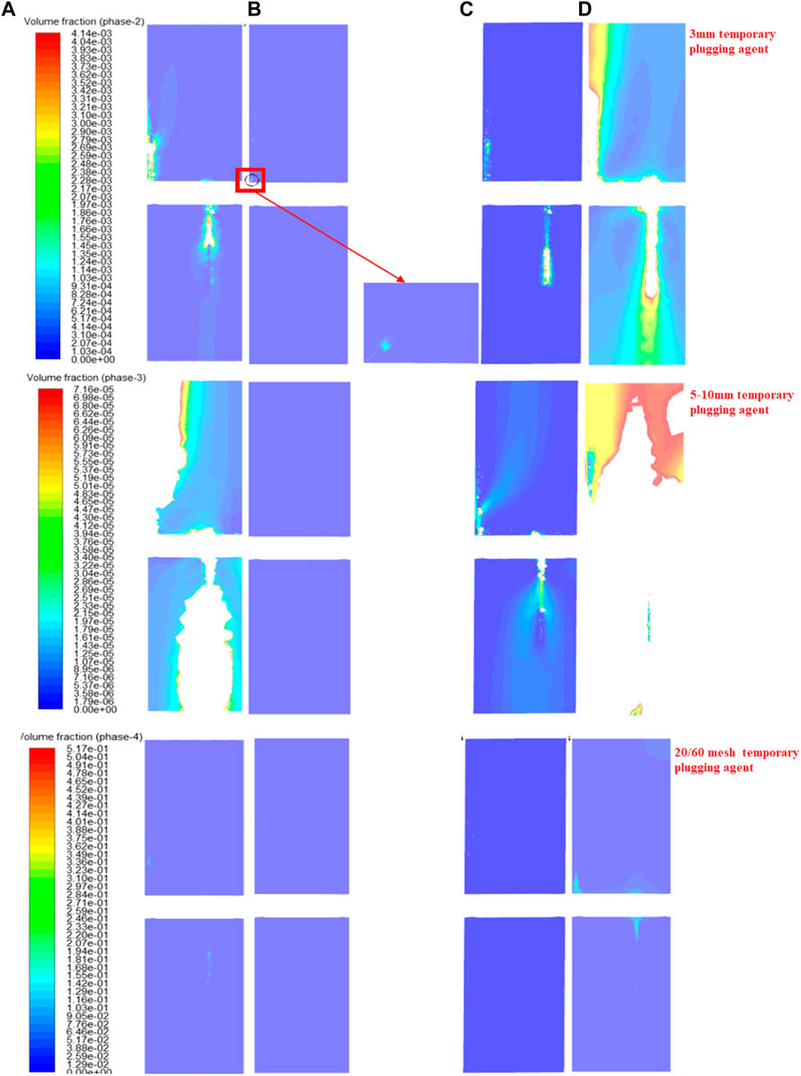
Figure 6. (A) Temporary blocking situation of the sixth cluster when the concentration of temporary plugging agent is 0.78%; (B) Temporary blocking situation of the sixth cluster when the concentration of temporary plugging agent is 1.56%; (C) Temporary blocking situation of the sixth cluster when the concentration of temporary plugging agent is 3.12%; (D) Temporary blocking situation of the sixth cluster when the concentration of temporary plugging agent is 6.24% (The blank space means temporary blockage, fluid can’t flow).
According to Figure 5, when the temporary plugging agent concentration is 0.78%, a certain degree of temporary plugging agent buildup is formed in the fifth cluster, but it is not located at the perforation depth. Therefore, the buildup of temporary plugging agent had some influence on the flow of fluid but did not form a blockage; at 1.56% and 3.12% of the temporary plugging agent concentration, although a certain mass of temporary plugging agent entered Cluster 1, no buildup and blockage were formed, which had little influence on the flow.
According to Figure 6, the temporary plugging effect of cluster 6 first decreases and then increases with the concentration of temporary plugging agent increasing:At a temporary plugging agent concentration of 0.78%, 3 mm temporary plugging agent and 5–10 mm temporary plugging agent form an effective temporary plug in and around the perforation depth; at a temporary plugging agent concentration of 1.56%, only 3 mm of temporary plugging agent formed an incomplete plug at the perforation depth; at 3.12% and 6.24% temporary plugging agent concentration, both 3mm and 5–10 mm temporary plugging agent formed plug at the perforation depth, and the temporary plugging area was larger at 6.24% concentration.
In summary, as the concentration of temporary plugging agent increases (0.78%, 1.56%, 3.12%, 6.24%), the temporary plugging effect first decreases and then increases. The temporary plugging effect was mainly seen in cluster 6; the worst effect was seen at 1.56% and the best at 6.24%; although the temporary plugging agent entered all other clusters, the effect was minimal.
3.1.2 Analysis of the causes of the phenomenon
Analysis of the causes of the relevant patterns and special cases that emerge from the simulation of different temporary plugging agent concentrations.
(1) Unlike other cases, at a temporary plugging agent concentration of 0.78%, the temporary plugging agent entered mainly clusters 5 and 6, rather than clusters 1 and 6, which are the main feed clusters, unlike field experience.
By combining the distribution of temporary plugging agent and liquid flow direction in the well, it is found that it is due to the small inertia of temporary plugging agent particles when the concentration of temporary plugging agent is too small, resulting in a smaller Stokes number, and the particles are more likely to change their movement direction with the liquid phase flow, as shown in Figure 7, the flow rate of the liquid phase in the heel cluster is much higher than that in the toe cluster, so at a concentration of 0.78%, the plugging agent is more likely to flow with the liquid phase at the heel end and enter the heel cluster, and it can not move to the area near the toe cluster.
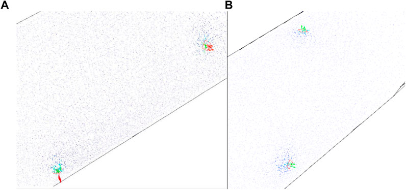
Figure 7. (A) Liquid phase velocity in the heel end cluster of the wellbore; (B) Liquid phase velocity in the toe end cluster of the wellbore.
(2) With the concentration of temporary plugging agent increasing, the temporary plugging effect of cluster 6, which is the most obvious, first decreases and then increases, and temporary plugging effect does not show a positive correlation with temporary plugging agent concentration. Combined with the previous conclusion that “the plugging agent particles are more likely to enter the heel cluster earlier with the liquid phase at 0.78% of the plugging agent concentration”, it can be concluded that this phenomenon is also the reason why the plugging effect of cluster 6 at 0.78% of the plugging agent concentration is better than that of cluster 6 at 1.56% of the plugging agent concentration: When the temporary plugging agent concentration reaches 1.56%, the total mass of temporary plugging particles passing through the wellbore section per unit time increases, and the inertia of the temporary plugging agent increases, gradually shifting towards the toe end of the wellbore and dispersing the temporary plugging agent particles entering the cluster at the heel end, and the temporary plugging effect of cluster 6 at the toe end naturally decreases compared to the temporary plugging agent concentration of 0.78%; after that, as the temporary plugging agent concentration increases, the temporary plugging effect of cluster 6 shows a complete positive correlation with it.
3.2 Temporary plugging agent mass
A total of 360 kg of plugging agent was injected during the temporary plugging and fracturing of section 5 of well A. Using this as a benchmark, the temporary plugging situation was studied when 180 kg and 540 kg of plugging agent were injected respectively, while keeping other conditions unchanged, and it was found that the plugging agent still entered clusters 1 and 6 as the main fluid intake clusters. The situation is shown in Figures 8, 9.
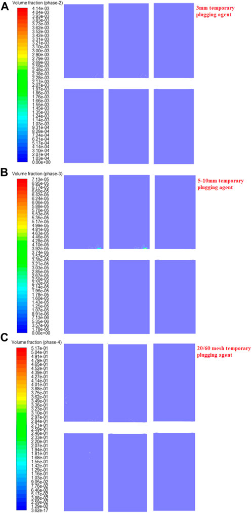
Figure 8. (A) Volume fraction of temporary plugging agent at wellbore toe end when the concentration of temporary plugging agent is 0.78%; (B) Volume fraction of temporary plugging agent at wellbore toe end when the concentration of temporary plugging agent is 1.56%; (C) Volume fraction of temporary plugging agent at wellbore toe end when the concentration of temporary plugging agent is 3.12%.
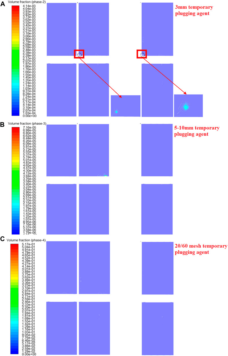
Figure 9. (A) Temporary blocking situation of the first cluster when the temporary plugging agent’s mass is 180kg; (B) Temporary blocking situation of the first cluster when the temporary plugging agent’s mass is 360kg; (C) Temporary blocking situation of the first cluster when the temporary plugging agent’s mass is 540 kg.
3.2.1 Comparison of simulation results
According to Figure 8, the temporary plugging of Cluster 1, one of the main feed clusters, did not change significantly with the mass of the injected temporary plugging agent changes.
According to Figure 9, at the beginning of the injection of the temporary plugging agent, for example, in Figure 9A, the amount of temporary plugging agent is too small to affect the flow of the fluid around cluster 6 when 180 kg temporary plugging agent is injected; with the mass of injected temporary plugging agent increasing, for example, in Figure 9B, at 360 kg, the 3 mm temporary plugging agent starts to form an incomplete plug at the sixth cluster perforation depth position. After the temporary plugging agent has formed an incomplete plug in cluster 6, the mass of temporary plugging agent injected is still increased, taking (c) in Figure 9 as an example, compared to the temporary plugging situation when 360 kg plugging agent is injected, there is no significant change in the temporary plugging situation near the perforation when 540 kg is injected.
3.2.2 Summary of the regularity
In summary, the mass of the temporary plugging agent has an influence on the effectiveness at the initial stage of temporary plugging, and the absolute quantity of temporary plugging agent is too small to affect the fluid in the vicinity of the perforation cluster. However, once the injected plugging agent mass reaches a certain level and the plugging effect is stable, for example, in Section 5 of well A, around 360kg, the influence of increasing plugging agent mass on the plugging effect becomes very low.
3.3 Temporary plugging agent particle size ratio
A total of 360 kg of temporary plugging agent was injected during the fracturing of Section 5 of well A, the mass of 3 mm temporary plugging agent is 140 kg, the mass of 5–10 mm temporary plugging agent is 40 kg and the mass of 20/60 mesh temporary plugging agent is 180kg, so the mass fractions of 3 mm temporary plugging agent is 38.89%, the mass fractions of 5–10 mm temporary plugging agent is 11.11% and the mass fractions of 20/60 mesh temporary plugging agent is 50%. Using this as a benchmark, the mass fractions of the three particle size temporary plugging agents were increased in turn and simulations were carried out, the details are shown in Table 2.
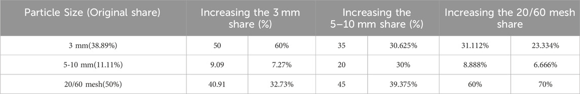
Table 2. Simulation calculation scheme of particle size ratio of temporary plugging agent.
According to the calculations, when adding 3 mm share and 5–10 mm share, the temporary plugging agent still enters mainly Cluster 1 and Cluster 6 (Figure 10). When adding 20/60 mesh temporary plugging agent share, a certain amount of temporary plugging agent enters each perforation cluster, resulting in a relatively uniform distribution of temporary plugging agent compared to other particle size solutions.
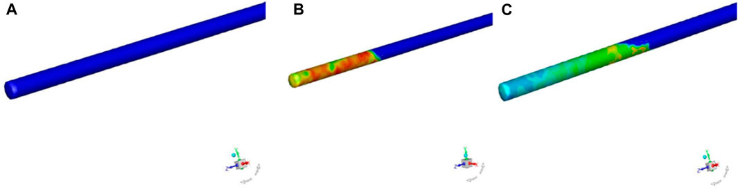
Figure 10. (A) Temporary blocking situation of the sixth cluster when the temporary plugging agent’s mass is 180 kg; (B) Temporary blocking situation of the sixth cluster when the temporary plugging agent’s mass is 360 kg; (C) Temporary blocking situation of the sixth cluster when the temporary plugging agent’s mass is 540 kg.
The results of the calculation of each temporary plugging agent particle size ratio are shown in Figure 11. As the results are similar, the temporary plugging situation of first cluster when the mass fraction of 3 mm temporary plugging agent is 60% which is used as an example.
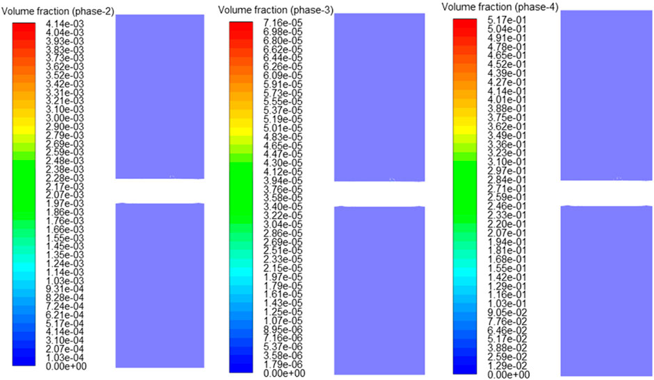
Figure 11. Examples of temporary plugging simulation of all particle size ratio of temporary plugging agent.
When the mass fraction of 3 mm temporary plugging agent is increased to 50% or 60%, the incomplete plug within cluster 6 disappears, the increase of the amount of 3 mm temporary plugging agent leads to an increased chance of collision, resulting in failure to enter the perforation; if the mass of injected temporary plugging agent and the mass fraction of 20/60 mesh temporary plugging agent are continuously increased, plug may be formed again, but it is not consistent with the actual site.
In summary, according to the simulation results, after adjusting the temporary plugging agent particle size ratio for the temporary plugging and fracturing of Section 5 of well A, the temporary plugging effect of the six scenarios did not show any improvement, but rather a decrease, indicating that the temporary plugging agent particle size ratio has less influence on the success of plug under the conditions of the actual temporary plugging agent mass in the field, and also indicating that the current temporary plugging agent particle size ratio of Section 5 of well A is more appropriate.
4 Summary
(1) According to the simulation study, it is found that the construction parameters in the temporary plugging and fracturing construction have the following influences on the temporary plugging effect in descending order: temporary plugging agent concentration > temporary plugging agent quality > temporary plugging agent particle size ratio, among which, the concentration of the temporary plugging agent has a significant influence on the temporary plugging effect, and the magnitude of the concentration of the temporary plugging agent has a direct correlation with the effect of the temporary plugging.
(2) The simulation found that when the concentration of temporary plugging agent is too small, due to the small inertia, it is easy to enter the heel cluster with the fracturing fluid in advance, and the possibility of entering the main feed cluster is reduced, thus affecting the effect of temporary plugging, which is less mentioned in the previous research, and the range of the suitable concentration of the temporary plugging agent should be clarified, and according to the simulation results of this paper, it is appropriate to control the concentration of the temporary plugging agent at the vicinity of 3.7% in the temporary plugging and fracturing construction. According to the simulation results of this paper, it is more appropriate to control the plugging agent concentration near 3.7% during the temporary fracturing construction.
(3) The “wellbore-near-well fracture model” established in this paper is divided into two parts for calculation, and the profile file is exported for connection, so that injection clusters and injection apertures are included in the scope of consideration, and at the same time, the Euler method and the formula for determining the volume fraction required for plugging are utilized, so that the DPM method and CFD-CFD can be avoided. At the same time, the Euler method and formula are utilized to determine the required volume fraction for plugging, which avoids the disadvantages of the DPM method and the CFD-DEM coupling method, and the simulation results obtained in this paper are more in line with the actual situation in the field compared with the conclusions of the previous researchers in this area.
(4) In order to take the shot hole cluster and shot hole perforation into consideration, the model in this paper is divided into two parts for calculation, which increases the complexity of the simulation. In the future, we can consider making efforts in the direction of building the shot hole section of the wellbore, the shot hole perforation, and the near-well fracture region into the same model, and using suitable calculation methods for simulation, which can simplify the simulation process.
(5) The simulation method of temporary plugging and fracturing is validated by fiber-optic monitoring data, and it can be used to simulate temporary plugging and fracturing under different working conditions, and to optimize the design of temporary plugging agent concentration, displacement and other parameters.
Data availability statement
The original contributions presented in the study are included in the article/Supplementary material, further inquiries can be directed to the corresponding author.
Author contributions
ZJ Zhang: Writing–original draft, Writing–review and editing. GX: Writing–original draft, Writing–review and editing. WM Wang: Writing–original draft, Writing–review and editing. LJ Li: Writing–original draft, Writing–review and editing. Shanzhi Shi: Writing–original draft, Writing–review and editing.
Funding
The author(s) declare financial support was received for the research, authorship, and/or publication of this article. 1. PetroChina Strategic Cooperation in Science and Technology Special Project - Research on Control Mechanism of Fracturing Effectiveness and Optimization of Fracturing Parameters in Conglomerate Reservoirs (ZLZX 2020-02-07-03) 2. PetroChina Strategic Cooperation in Science and Technology Special Project-Research on the Mechanism of Efficient Utilization of the Upper and Lower Desserts of Jimusar and Three-dimensional Development Technology (ZLZX 2020-02-07-05) 3. Key R&D projects of Karamay-R&D and application of super large true triaxial hydraulic fracturing simulation experimental device (20212022zdyf0041) (This fund is provided by the government of Karamay.)
Conflict of interest
Authors GX and RG were employed by Xinjiang Taiqi Petroleum Technology Co Ltd. Authors WM, LJ, and SS were employed by Xinjiang Oilfield Company. Author RG was employed by CNPC Engineering Technology R&D Company Limited.
The remaining authors declare that the research was conducted in the absence of any commercial or financial relationships that could be construed as a potential conflict of interest.
Publisher’s note
All claims expressed in this article are solely those of the authors and do not necessarily represent those of their affiliated organizations, or those of the publisher, the editors and the reviewers. Any product that may be evaluated in this article, or claim that may be made by its manufacturer, is not guaranteed or endorsed by the publisher.
References
Chen, ZHENG, Wang, D., Qin, H., et al. (2022). Numerical simulation of the transport pattern of fracture temporary plugging agent in rough fractures. J. Northeast Petroleum Univ. 46 (01), 88–103.
Dongfeng, H., Lan, R., Zhenxiang, L., Zhao, J., Lin, R., and Jiang, T. (2022). Simulation of fracture control during temporary plugging at fracture openings in deep and ultra-deep shale-gas horizontal wells. Nat. Gas. Ind. B 9 (5), 487–496. doi:10.1016/j.ngib.2022.10.002
Jiang, T., Wang, H., Zhao, J., et al. (2023). Optimization of key process for multi-stage double temporary plug fracturing of deep shale gas horizontal wells. Nat. Gas. Ind. 43 (11), 100–108.
Kai, L. I., Zhao, Y., Xie, H., et al. Simulation of gas-driven development of fractured horizontal wells with scuttling pattern and research on the technology of dissection and blocking, China University of Geosciences (Wuhan),Xi'an University of Petroleum, Shaanxi Petroleum Society. Proceedings of 2023 International Conference on Oil and Gas Field Exploration and Development III. Research Institute of Experimentation and Testing, Xinjiang Oilfield Branch, PetroChina; Key Laboratory for Exploration and Development of Conglomerate Reservoirs, China National Petroleum Corporation, 2023: 7. doi:10.26914/c.cnkihy.2023.053625
Li, L. I. (2006). Skin factor model and numerical simulation of horizontal well considering completion mode and damage effect. Chengdu, China: Southwest Petroleum University.
Li, X., Yin, Q. I., Li, Z., et al. (2016). Mixed water volume fracturing technology for temporary plugging of old Wells in tight reservoirs in an 83 block, Ordos Basin [J]. Pet. Geol. Recovery Effic. 23 (06), 120–126.
Lv, R., Liu, B., and Lin, A. N. (2020). Study on the transport and sealing pattern of temporary plug balls for horizontal well steering and fracturing. China Pet. Mach. 48 (07), 117–122.
Qin, H. (2021). Study on the transport and sealing pattern of temporary plugging agent in dry hot rock fractures under the action of heat flow. Beijing, China: Beijing Institute of Petrochemical Technology.
Sun, Q., Zhang, J., Lv, W., et al. (2012). Numerical simulation of flow condition in hydraulic sandblasting perforation. Inn. Mong. Petrochem. Ind. 38 (09), 15–17.
Tian, Y. (2019). Flow simulation study and application of fracture temporary plugging agent based on CFD-DEM method. Beijing, China: China University of Petroleum.
Wang, B. (2016a). Study on fracturing fluid flow and proppant migration in perforation passage. Xi'an, China: Xi’an Shiyou University.
Wang, B. (2016b). Study of fracturing fluid flow and proppant transport patterns in the shot hole channel. Xi'an, China: Xi’an Shiyou University.
Wang, B., Jun, L. I., Liu, G., et al. (2019). Physical simulation of near-wellbore fracture propagation based on staggered fixed surface perforation. Petroleum Explor. Dev. 46 (06), 1187–1196.
Wu, G., Xing, Y., Yan, L. V., et al. (2016). Experimental analysis of oil-water flow resistance coefficient in porous media. Exp. Technol. Manag. 33 (10), 34–37.
Xie, J., Wang, C., Yin, H., et al. (2021). Research and application of refracturing technology in jimsar shale oil Wells [J]. Chem. Eng. Oil Gas 50 (04), 100–103.
Xin, C., Xingyi, W., Chunhe, Y., et al. (2024). Simulation and optimization of fracture pattern in temporary plugging fracturing of horizontal shale gas wells. Fuel, 359.
Xuesong, X., Guangai, W., Jun, Z., Zhang, A., Hou, Y., Xie, X., et al. (2023). Finite element study on the initiation of new fractures in temporary plugging fracturing. Front. Phys. 11, 11. doi:10.3389/fphy.2023.1227917
Yi, FENG (2023). Study of the transport mechanism of plugging particles in peri-well fractures. Chengdu, China: Southwest Petroleum University.
Yifan, P., Song, L., Dazhen, T., et al. (2023). Numerical simulation study on the effectiveness of temporary plugging and fracturing in deep coal seam to construct complex fracture network. Geoenergy Sci. Eng., 227.
Yong, G., Zhanwei, Y., Feilong, G., Deng, S., and Wu, S. (2023). Mechanical study and key parameter optimization of temporary plugging fracturing in tight reservoirs. J. Phys. Conf. Ser. 2610 (1), 012043. doi:10.1088/1742-6596/2610/1/012043
Zhang, G. (2018). Research and application of re-fracturing technology in Niuquan Lake sandstone reservoir. Chem. Engineering&Equipment (09), 75–80.
Keywords: temporary plugging, numerical simulation, porous media, “wellbore-fracture” coupling model, agent concentration
Citation: Jingchen Z, Xiaodong G, Mingxing W, Jie L, Shanzhi S and Guangcong R (2024) Simulation of temporary plugging agent transport and optimization of fracturing parameters based on fiber optic monitoring data. Front. Chem. Eng. 6:1324907. doi: 10.3389/fceng.2024.1324907
Received: 20 October 2023; Accepted: 31 January 2024;
Published: 20 May 2024.
Edited by:
Federica Raganati, National Research Council (CNR), ItalyReviewed by:
Paola Ammendola, National Research Council (CNR), ItalyFrancesca Raganati, University of Naples Federico II, Italy
Andrew Nosakhare Amenaghawon, University of Benin, Nigeria
Copyright © 2024 Jingchen, Xiaodong, Mingxing, Jie, Shanzhi and Guangcong. This is an open-access article distributed under the terms of the Creative Commons Attribution License (CC BY). The use, distribution or reproduction in other forums is permitted, provided the original author(s) and the copyright owner(s) are credited and that the original publication in this journal is cited, in accordance with accepted academic practice. No use, distribution or reproduction is permitted which does not comply with these terms.
*Correspondence: Zhang Jingchen, amluZ2NoZW4xMjBAMTI2LmNvbQ==