- 1Center of Smart Materials and Devices, State Key Laboratory of Advanced Technology for Materials Synthesis and Processing, School of Material Science and Engineering, Wuhan University of Technology, Wuhan, China
- 2State Key Laboratory of New Ceramics and Fine Processing, School of Materials Science and Engineering, Tsinghua University, Beijing, China
- 3Foshan (Southern China) Institute for New Materials, Foshan, China
- 4Qingtao Research Institute, Qingtao Energy Development Inc., Kunshan, China
Bromine-rich lithium argyrodite electrolytes with high ionic conductivity and low cost are promising for the replacement of flammable liquid electrolytes and separators in lithium-ion batteries. However, the synthesis process of argyrodite electrolytes is usually complex and time-consuming. We use a facile solid-state reaction method to obtain a highly Li-ion conductive Li5.5PS4.5Br1.5 (LPSB). The influence of annealing temperature on the phase and ionic conductivity of the LPSB was investigated for the first time. High ionic conductivity of 5.21 × 10⁻³ S cm−1 at room temperature for the LPSB with minor LiBr impurity was achieved by direct annealing at 430°C for 8 h. The In/InLi | LPSB | LiCoO2@ LiNb0.5Ta0.5O3 (LCO(coated))-LPSB cell with 8.53 mg cm−2 LCO loading shows a discharge capacity of 102 mAh g−1 with high-capacity retention of 93% after 70 cycles at 0.5 mA cm−2 at 30°C.
Introduction
Lithium-ion batteries are an effective energy storage system that are widely used in portable electronic devices and electric vehicles (Robinson et al., 2014). However, lithium dendrite growth and the use of flammable organic liquid electrolytes increases the safety issues of state-of-the-art commercial lithium-ion batteries (Choi et al., 2012). All-solid-state batteries (ASSBs) with solid electrolytes enable the utilization of high-voltage/high-capacity cathode materials and lithium anode, which is expected to increase the safety and achieve high energy and power density of batteries (Janek et al., 2016; Hatzell et al., 2020; Randau et al., 2020; Wang et al., 2020; Fan et al., 2021).
Among the various kinds of inorganic solid electrolytes (e.g., oxide, sulfide, and halide), sulfide solid electrolytes have drawn a lot of attention due to their high ionic conductivity and good formability (Li et al., 2020; Ohno et al., 2020). Lithium argyrodites with high room-temperature ionic conductivity and relatively low cost among many sulfide solid electrolytes possess great potential for achieving high-performance ASSBs (Wang et al., 2019; Zhou et al., 2021). For example, Yu et al. reported Li6PS5Br electrolyte with a high ionic conductivity of 2.58 × 10⁻³ S cm−1, which was prepared by optimizing the annealing temperature in a solid-state reaction (Yu et al., 2019). Gautam et al. found that by tailoring the cooling rate, a higher degree of site-disorder and shorter Li+–Li+ distances, which are responsible for the intercage jumps, were achieved, leading to an obvious increase in the ionic conductivity of Li6PS5Br solid electrolyte (Gautam, 2019; Gautam 2020).
Recently, Yu et al. have reported a bromine-rich lithium argyrodite (Li5.5PS4.5Br1.5 (LPSB)) solid electrolyte with a high ionic conductivity of 4.17 × 10⁻³ S cm−1, which was synthesized by ball milling at 500 rpm for 15 h followed by annealing at 400 °C for 10 h (Yu et al., 2020). However, the process is time-consuming, which impedes its large-scale application in ASSBs. Wang et al. reported a facile method to prepare the Li6PS5Cl electrolyte with a high ionic conductivity of 3.15 × 10⁻³ S cm−1 at room temperature by annealing at 550 °C for 10 min (Wang et al., 2018). However, using a one-pot solid-state reaction method by direct annealing for LPSB has not been reported. Additionally, the effects of annealing temperature on the phase and ionic conductivity of bromine-rich lithium argyrodite have not been studied.
In this work, we investigated the influence of annealing temperature on the phase and ionic conductivity of LPSB for the first time. The LPSB electrolyte with minor LiBr impurity and a high ionic conductivity of 5.21 × 10⁻³ S cm−1 at room temperature was achieved by directly annealing at 430 °C for 8 h. We also assembled ASSBs with LiCoO2@ LiNb0.5Ta0.5O3 (LCO(coated))-LPSB as a composite cathode, LPSB as a solid electrolyte, and In/InLi as an anode. The cell with the LCO(coated)-LPSB cathode and 8.53 mg cm−2 LCO loading shows a discharge capacity of 102 mAh g−1 and a high-capacity retention of 93% after 70 cycles at 0.5 mA cm−2 at 30 °C. These results demonstrate that the LPSB electrolyte is a good solid electrolyte candidate used in ASSBs.
Experimental section
Synthesis of Li5.5PS4.5Br1.5
Li5.5PS4.5Br1.5 solid electrolytes were prepared using a solid-state reaction method and reagent-grade Li2S (Alfa, 99.9%), LiBr (Alfa, 99.9%), and P2S5 (Sigma Aldrich, 99%) powders as starting materials. All raw materials were weighed according to a Li2S/P2S5/LiBr molar ratio of 4:1:3 and mixed via ball milling using a planetary ball mill apparatus (Fritsch Pulverisette 7 premium line). The milling speed was fixed at 100 rpm and the milling time was 2 h. All procedures were conducted under Ar atmosphere in a dry glovebox (O2 < 0.1 ppm, H2O < 0.1 ppm). The precursor was then pressed into pellets and filled into quartz ampoules. Next, quartz ampoules were sealed under a high vacuum. Finally, ampoules were placed into a furnace and annealed at 390, 410, 430, or 450 °C for 8 h with a heating rate of 90 °C h−1, respectively. The ampoules were cooled to room temperature naturally in a furnace. The samples that were annealed at different temperatures were denoted as 390-8h, 410-10h, 430-10h, and 450-10h, respectively.
Material characterization
The X-ray diffraction (XRD) patterns were collected over a 2θ range of 10–70 ° on a PANalytical Empyrean powder diffractometer with a Cu Kα radiation source to identify the phases of samples. To prevent an unwanted reaction with moisture and oxygen, the samples were sealed in an airtight container covered with a thin polyimide film. Raman spectra were collected using a Raman spectrometer (LabRAM HR Evolution, Horiba) with an excitation wavelength of 532 nm. The samples were sealed airtight with a quartz glass cover in the glovebox to maintain an inert atmosphere during the measurement. Scanning electron microscopy (SEM, Zeiss Merlin field-emission) with energy dispersive X-Ray (EDX) spectroscopy was used to examine the morphology and composition of the samples at an acceleration voltage of 15 kV.
Electrochemical performance measurements
Approximately 0.12 g of the LPSB powder was pressed into pellets with a diameter of 12 mm under 150 MPa for the ionic conductivity measurement. Two stainless steel disks were attached to the pellets as current collectors. The AC impedance measurement was conducted using an impedance analyzer (ZAHNER-elektrik IM6) in the frequency range of 1 MHz to 1 Hz with an applied voltage of 50 mV. The ionic conductivity σ was calculated using the equation σ = L/RS, where R is the total resistance of the solid electrolyte, L is the thickness of solid electrolyte pellets, and S is the area of the solid electrolyte pellets.
A Lithium metal | solid electrolyte | stainless steel cell was conducted by cyclic voltammetry (CV) using a potentiostat (Biologic VMP3) at a scan rate of 0.2 mV s−1 and at voltages range from −0.5 V to 5 V at room temperature. About 0.15 g of solid electrolyte powder was pressed into the pellet with a diameter of 10 mm under 150 MPa for the direct-current (DC) polarization tests. The DC tests were conducted using a blocking stainless steel | solid electrolyte | stainless steel cell with applied constant voltages of 0.2 V, 0.4 V, 0.6 V, 0.8 V, and 1 V for 6 h.
ASSB cells were assembled as follows. For the In/InLi | LPSB | LCO(coated)- LPSB cells, 90 mg of LPSB powder was first pressed in a PEEK housing at 150 MPa with a diameter of 10 mm. The LCO(coated)-LPSB composite cathodes were prepared via hand-mixing of the LCO(coated) (prepared according to previous work) (Yada et al., 2015; Wang et al., 2021a) and LPSB at a weight ratio of 70:30. Then, the LCO(coated)-LPSB cathode was spread onto one side of the electrolyte pellet and pressed at 120 MPa. Afterwards, thin lithium foil was put on the other side of the pellet followed by an indium foil, and the cell was pressed at 150 MPa for 3 min. Cells were tested in a homemade cell at a constant pressure of ∼120 MPa at 30 °C using a battery test system (LANHE, CT3001A, China) in a voltage range of 2.0–3.6 V (vs. In/InLi) and corresponding to 2.6–4.2 V (vs. Li+/Li). For the In/InLi | LPSB | LPSB-MWCNTs cells, the cell assembly procedures were similar to the above cells with LCO(coated)-LPSB composite. The LPSB-MWCNTs cathode was prepared by ball milling the mixture of LPSB and MWCNTs at a weight ratio of 80:20 at 300 rpm for 1.5 h. The cells were tested at a constant pressure of ∼150 MPa at 60 °C in a voltage range of 0–3 V (vs. In/InLi) corresponding to 0.6–3.6 V (vs. Li+/Li).
The step-wise CV experiments of the In/InLi | LPSB | LPSB-MWCNTs were performed using a VMP3 potentiostat (Biologic) at 25 °C. Each experiment started from around the open circuit voltage (OCV) to the chosen reversal potential (vs. In/InLi as reference potential) with a scan speed of 0.1 mV s−1, followed by the reverse scan at −0.1 mV s−1 and finalized at the OCV. The following scan was performed to the next reversal potential, which was lower or higher by 0.1 V for the reductive and oxidative runs, respectively. The reductive or oxidative step-wise CV measurements were performed down to 0 V or up to 2.1 V (vs. In/InLi).
Results and Discussion
Figure 1A shows the XRD patterns of the LPSB samples synthesized by annealing at 390, 410, 430, or 450 °C for 8h. For the 390-10 h samples, the main diffraction peaks are indexed as crystalline Li5.5PS4.5Br1.5, and the minor peaks at 27.9 ° and 32.3 ° are attributed to the LiBr impurities (Yu et al., 2019). The intensity of the diffraction peaks for LiBr impurities gradually decrease until the annealing temperature increases to 430 °C. As the annealing temperature increases to 450 °C, the intensity of LiBr impurity increases again. Thus, 430 °C is the optimal annealing temperature to obtain the LPSB electrolyte with an almost pure Li5.5PS4.5Br1.5 phase.
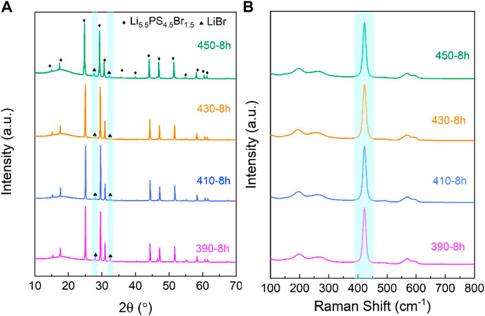
FIGURE 1. XRD patterns (A) and Raman spectra (B) of the LPSB samples synthesized by solid-state reaction at different temperatures for 8 h.
The Raman spectra of LPSB samples synthesized by the solid-state reaction at different temperatures for 8 h are shown in Figure 1B. The main peak at 484 cm−1 for all samples is attributed to the stretching of PS43− (Wang et al., 2018) and indicates the presence of the high ionic conductivity phase Li5.5PS4.5Br1.5. The Raman results are in accordance with the XRD data above.
The Nyquist spectra of LPSB solid electrolytes measured at room temperature are shown in Figure 2A. The resistance of the LPSB solid electrolyte decreases as the annealing temperature increases from 390 to 430 °C. As the temperature increases to 450 °C, the resistance increases again. The ionic conductivities of the LPSB electrolytes that are annealed at different temperatures are shown in Figure 2B. The ionic conductivity of the 390-8 h sample is 3.2 × 10⁻³ S cm−1. As the annealing temperature increases, the ionic conductivity of the LPSB electrolyte increases and reaches a maximum at 430 °C and then decreases. The ionic conductivity of the 430-8 h sample is as high as 5.21 × 10⁻³ S cm−1 at room temperature. From 390 to 430 °C, the increase of the ionic conductivity is due to the reduction of the LiBr impurity with poor ionic conductivity (Yu et al., 2019). When the temperature continues to increase, the LiBr impurity increases again and leads to a decrease of the ionic conductivity. Thus, the optimized annealing temperature is 430 °C. Compared with the reported LPSB solid electrolyte with an ionic conductivity of 4.17 × 10⁻³ S cm−1 synthesized by ball milling at 500 rpm for 15 h and followed by annealing at 400 °C for 10 h (Yu et al., 2020), our synthesis route was able to obtain the LPSB solid electrolyte with higher ionic conductivity in a shorter time. This facile method can save energy and increase production efficiency.
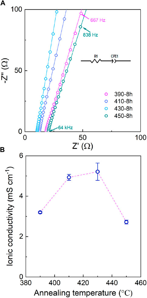
FIGURE 2. (A) Nyquist plots and (B) ionic conductivities of the LPSB electrolytes at room temperature as a function of annealing temperature.
In addition, the electronic conductivity of the 430-8 h sample is 3.8 × 10⁻¹⁰ ± 1.1×10⁻¹⁰ S cm−1 (Figure 3), which is 7 orders of magnitude smaller than its ionic conductivity. This low electronic conductivity of the LPSB electrolytes will help alleviate the decomposition of the solid electrolyte in the composite cathode (Wang 2021).
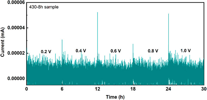
FIGURE 3. DC polarization of the 430-8 h sample. The blocking stainless steel | solid electrolyte | stainless steel cell was applied to constant voltages of 0.2 V, 0.4 V, 0.6 V, 0.8 V, and 1 V for 6 h for the DC tests.
Figure 4 shows the SEM images of the 430-8 h (a) powder and (e) pellets, and corresponding sulfur (b, f), phosphorus (c, g), and bromine (d, h) EDX mappings. The morphology of the 430-8 h powder (Figure 4A) shows that the particle size is distributed from submicron to ∼15 μm. Good contact between solid electrolyte particles is also achieved in the 430-8 h pellet prepared by cold pressing without sintering (Figure 4E). In addition, the S, P, and Br elements are homogeneously distributed among the whole solid electrolyte particles (Figures 4B–D) and pellets (Figure 4F,G,H), which indicates that no elements aggregate during the solid-state reaction process.
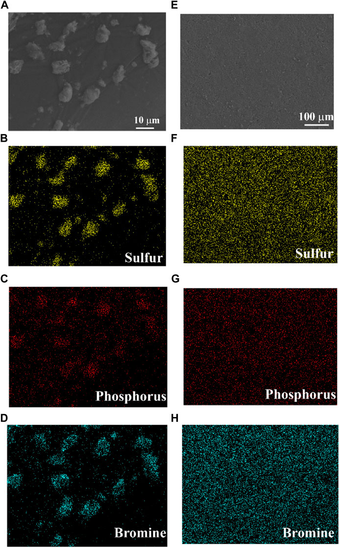
FIGURE 4. SEM images of the 430-8 h (A) powder and (E) pellets and corresponding sulfur (B and F), phosphorus (C and G), and bromine (D and H) EDX mappings.
The electrochemical window obtained by CV is important to evaluate the stability of the LPSB electrolyte against lithium metal. Traditional CV measurements with stainless steel as the working electrode and Li metal as the reference electrode are typically used to determine the electrochemical window of solid electrolytes. There is no significant current attributed to the solid electrolyte decomposition in the potential range from -0.5 to 5 V vs. Li+/Li (Figure 5A), which indicates that the electrochemical window of the LPSB electrolyte is 0–5 V (vs. Li+/Li). However, this method does not reflect the real poor redox reaction kinetics of the LPSB electrolytes and usually overestimates their electrochemical window (Dewald et al., 2019). Replacing the inert electrode with an LPSB-MWCNTs electrode increases the decomposition reactions and enhances the measurement accuracy for the electrochemical window of the LPSB electrolytes (Wang et al., 2021b). A gradual increase in the negative current below 1 V (vs. In/InLi) and its rapid increase below 0.6 V (vs. In/InLi) is observed from the reductive step-wise CV shown in Figure 5B. As for the oxidative step-wise CV shown in Figure 5C, an obvious increase in the positive current is observed over 1.8 V (vs. In/InLi) and continues to grow. Therefore, the synthesized LPSB solid electrolyte exhibits a reasonable intrinsic electrochemical window of 1.6–2.4 V (vs. Li+/Li).
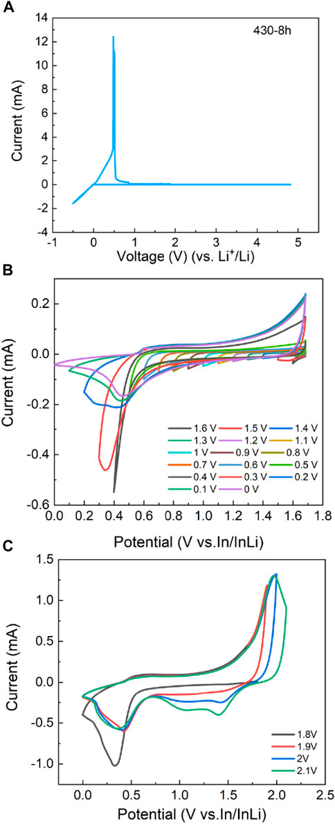
FIGURE 5. (A) The CV curve of the stainless steel | LPSB |Li cell shows no significant current due to solid electrolyte decomposition. The (B) reductive and (C) oxidative step-wise CV for LPSB electrolyte using LPSB-MWCNTs as a working electrode and In/InLi as a reference electrode demonstrates an apparent redox behavior of the LPSB-MWCNTs composite. For the reductive step-wise CV, a gradual increase in the negative current is observed as the voltage scans below 1 V (vs. In/InLi), which indicates the lower limit of the electrochemical window of LPSB. For the oxidative step-wise CV, a rapid increase in oxidative current is recorded as the voltage scans above 1.8 V (vs. In/InLi) and shows the upper limit of the electrochemical window of LPSB.
The electrochemical performance of the In/InLi | LPSB | LCO(coated)-LPSB ASSB at 30 °C is shown in Figure 6. As shown in Figure 6A, the cell with 8 mg cm−2 active material loading delivers an initial high discharge capacity of 116 mAh g−1 and an initial Coulombic efficiency of 92.2% at 0.2 mA cm−2. After 20 cycles, the discharge capacity slightly decreases to 110.6 mAh g−1. A high Coulombic efficiency of approximately 100% after the second cycle and a slight increase of overpotential are observed after 20 cycles (Figure 6B), which explain the good cycling performance of the cell. When the cell with 8.53 mg cm−2 active material loading is cycled at 0.5 mA cm−2, the discharge capacity degrades slightly to 102 mAh g−1 after 70 cycles with a high capacity retention of 93% (Figure 6C). The overpotential increases slightly after 70 cycles (Figure 6D) and demonstrates superior cycling stability of the ASSB.
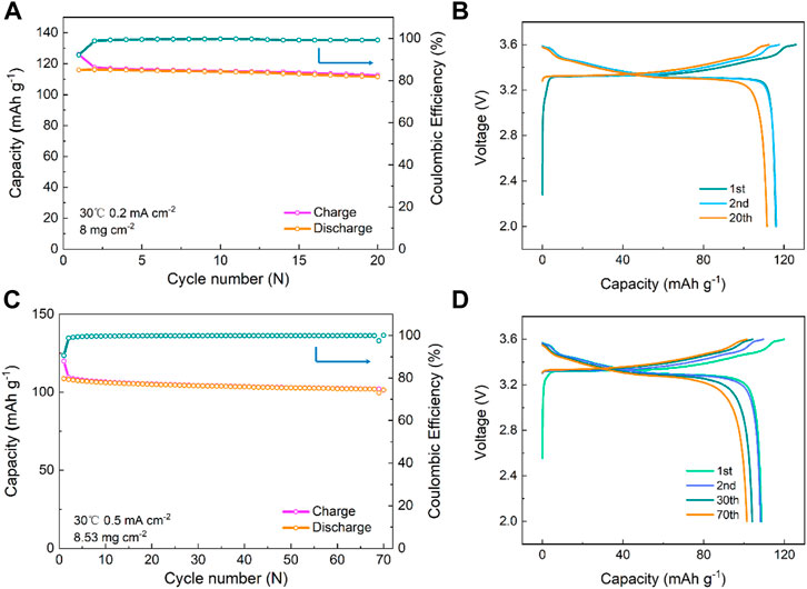
FIGURE 6. Cycling performance of the In/InLi | LPSB | LCO(coated)-LPSB ASSBs at different current densities of (A) 0.2 mA cm−2 and (C) 0.5 mA cm−2 at 30 °C and (B and D) the corresponding discharge–charge voltage profiles of the cells at different cycles.
Due to the intrinsic narrow electrochemical window of LPSB, the decomposition products of LPSB might be able to act as cathode active materials. The ASSBs with LPSB-MWCNTs as the composite cathode, LPSB as a solid electrolyte, and In/InLi as an anode are fabricated to clarify the reversible electrochemical reaction activity of the decomposition products from the LPSB. The electrochemical performance of the In/InLi | LPSB | LPSB-MWCNTs ASSB at 60 °C is shown in Figure 7. As shown in Figure 7A, the specific capacity of the cell with 8.15 mg cm−2 LPSB cathode loading shows a high discharge capacity of 494 mAh g−1 (the specific capacity was calculated based on the total mass of LPSB in the composite cathode) at 0.5 mA cm−2 after the second cycle. After 30 cycles, the discharge capacity first rapidly decreases and then slowly changes to 301 mAh g−1.
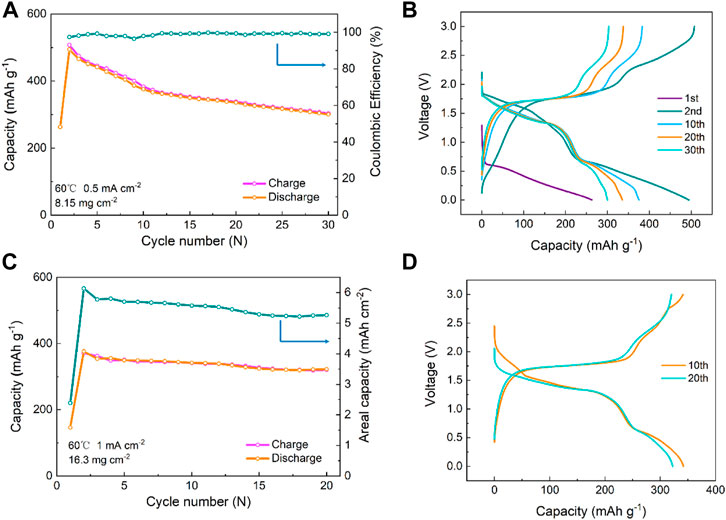
FIGURE 7. Cycling performance of the In/InLi | LPSB | LPSB-MWCNTs ASSBs at 60 °C (A) with cathode LPSB loading of 8.15 mg cm−2 at 0.5 mA cm−2 and (C) with cathode LPSB loading of 16.3 mg cm−2 at 1 mA cm−2 and (B and D) the corresponding discharge–charge voltage profiles of the cells at different cycles.
The discharge–charge voltage profiles of the cells with LPSB-MWCNTs cathode cycling at 0.5 mA cm−2 are presented in Figure 7B. There are two clear processes below and above 0.6 V (vs. In/InLi) during the discharge process and at least two other processes below and above 2 V (vs. In/InLi) during the charge process, which might be due to the sulfur and phosphorus redox activity of the decomposition products of the LPSB solid electrolyte as active materials (e.g. 4S2−+ Px− ↔ PS43− + (5 + x) e−; 2 PS43− ↔ P2S74− + S + 2e− ↔ P2S62− + 2S + 4e−) (Ohno et al., 2021; Wang et al., 2021c).
Increasing the cathode active material loading is essential for increasing energy density and the specific energy of ASSBs to fulfill commercial requirements. When the LPSB cathode loading increases to 16.3 mg cm−2 (Figure 7C), the discharge capacity slightly decreases to 323 mAh g−1 after 20 cycles (equivalent to 5.26 mAh cm−2) at 1 mA cm−2. In addition, a mild capacity degradation can be seen from the discharge curves for the 10th and 20th cycles (Figure 7D), which demonstrates that the decomposition products of LPSB show reversible electrochemical reaction activity.
Conclusion
A facile solid-state reaction method without the traditional high energy ball-milling process has been utilized to prepare bromine-rich lithium argyrodite solid electrolytes. The LPSB solid electrolyte with minor LiBr impurity and a high ionic conductivity of 5.21 × 10⁻³ S cm−1 at room temperature was obtained via annealing at 430 °C for 8 h. The ASSBs with LCO(coated)-LPSB or LPSB-MWCNTs as the composite cathode, LPSB as the solid electrolyte, and In/InLi as an anode is assembled. A discharge capacity of 102 mAh g−1 with a high-capacity retention of 93% after 70 cycles at 30 °C at 0.5 mA cm−2 was achieved in the cell with 8.53 mg cm−2 LCO loading. In addition, the decomposition products of the LPSB solid electrolyte are demonstrated to possess reversible redox activity. A high areal capacity of up to 5.26 mAh cm−2 after 20 cycles at 60 °C at 1 mA cm−2 in the In/InLi | LPSB | LPSB-MWCNTs cell was also achieved. These results show that the LPSB electrolyte is applicable as an electrolyte for ASSBs.
Data availability statement
The original contributions presented in the study are included in the article/supplementary material, and further inquiries can be directed to the corresponding author.
Author contributions
SW designed the experiments and conducted the main experiments and analyses. XW conducted the SEM measurements. YL conducted the XRD measurements. SW and YX prepared the solid electrolyte samples. SW and C-WN wrote the manuscript. All authors discussed the results and contributed to the preparation of the manuscript.
Funding
This work was supported by the Basic Science Center Program of the National Natural Science Foundation of China (NSFC) under Grant No. 51788104, the Fundamental Research Funds for the Central Universities (WUT: 2022IVA005), the Guangdong Basic and Applied Basic Research Foundation (Grant No. 2021A1515110312), and NSFC under Grant No. 52027817.
Conflict of interest
HH was employed by Qingtao Energy Development Inc.
The remaining authors declare that the research was conducted in the absence of any commercial or financial relationships that could be construed as a potential conflict of interest.
Publisher’s note
All claims expressed in this article are solely those of the authors and do not necessarily represent those of their affiliated organizations or those of the publisher, the editors and the reviewers. Any product that may be evaluated in this article, or claim that may be made by its manufacturer, is not guaranteed or endorsed by the publisher.
References
Choi, N. S., Chen, Z., Freunberger, S. A., Ji, X., Sun, Y. K., Amine, K., et al. (2012). Challenges facing lithium batteries and electrical double-layer capacitors. Angew. Chem. Int. Ed 51 (40), 9994–10024. doi:10.1002/anie.201201429
Dewald, G. F., Ohno, S., Kraft, M. A., Koerver, R., Till, P., Vargas-Barbosa, N. M., et al. (2019). Experimental assessment of the practical oxidative stability of lithium thiophosphate solid electrolytes. Chem. Mat 31 (20), 8328–8337. doi:10.1021/acs.chemmater.9b01550
Fan, L. Z., He, H., and Nan, C. W. (2021). Tailoring inorganic–polymer composites for the mass production of solid-state batteries. Nat. Rev. Mat 6 (11), 1003–1019. doi:10.1038/s41578-021-00320-0
Gautam, A., Sadowski, M., Ghidiu, M., Minafra, N., Senyshyn, A., Albe, K., et al. (2020). Engineering the site‐disorder and lithium distribution in the lithium superionic argyrodite Li6PS5Br. Adv. Energy Mat 11 (5), 2003369. doi:10.1002/aenm.202003369
Gautam, A., Sadowski, M., Prinz, N., Eickhoff, H., Minafra, N., Ghidiu, M., et al. (2019). Rapid crystallization and kinetic freezing of site-disorder in the lithium superionic argyrodite Li6PS5Br. Chem. Mat 31 (24), 10178–10185. doi:10.1021/acs.chemmater.9b03852
Hatzell, K. B., Chen, X. C., Cobb, C. L., Dasgupta, N. P., Dixit, M. B., Marbella, L. E., et al. (2020). Challenges in lithium metal anodes for solid-state batteries. ACS Energy Lett 5 (3), 922–934. doi:10.1021/acsenergylett.9b02668
Janek, J., and Zeier, W. G. (2016). A solid future for battery development. Nat. Energy 1 (9), 16141. doi:10.1038/nenergy.2016.141
Li, X., Liang, J., Yang, X., Adair, K. R., Wang, C., Zhao, F., et al. (2020). Progress and perspectives on halide lithium conductors for all-solid-state lithium batteries. Energy Environ. Sci 13 (5), 1429–1461. doi:10.1039/c9ee03828k
Ohno, S., Banik, A., Dewald, G. F., Kraft, M. A., Krauskopf, T., Minafra, N., et al. (2020). Materials design of ionic conductors for solid state batteries. Prog. Energy 2 (2), 022001. doi:10.1088/2516-1083/ab73dd
Ohno, S., Rosenbach, C., Dewald, G. F., Janek, J., and Zeier, W. G. (2021). Linking solid electrolyte degradation to charge carrier transport in the thiophosphate‐based composite cathode toward solid-state lithium-sulfur batteries. Adv. Funct. Mat 31 (18), 2010620. doi:10.1002/adfm.202010620
Randau, S., Weber, D. A., Kötz, O., Koerver, R., Braun, P., Weber, A., et al. (2020). Benchmarking the performance of all-solid-state lithium batteries. Nat. Energy 5, 259–270. doi:10.1038/s41560-020-0565-1
Robinson, A. L., and Janek, J. (2014). Solid-state batteries enter EV fray. MRS Bull. 39 (12), 1046–1047.doi:10.1557/mrs.2014.285
Wang, S., Fang, R., Li, Y., Liu, Y., Xin, C., Richter, F. H., et al. (2021a). Interfacial challenges for all-solid-state batteries based on sulfide solid electrolytes. J. Materiomics 7, 209–218. doi:10.1016/j.jmat.2020.09.003
Wang, S., Tang, M., Zhang, Q., Li, B., Ohno, S., Walther, F., et al. (2021b). Lithium argyrodite as solid electrolyte and cathode precursor for solid-state batteries with long cycle life. Adv. Energy Mat 11 (31), 2101370. doi:10.1002/aenm.202101370
Wang, S., Xu, X., Zhang, X., Xin, C., Xu, B., Li, L., et al. (2019). High-performance Li6PS5Cl-based all-solid-state lithium-ion batteries. J. Mat. Chem. A Mat 7 (31), 18612–18618. doi:10.1039/c9ta04289j
Wang, S., Zhang, W., Chen, X., Das, D., Ruess, R., Gautam, A., et al. (2021c). Influence of crystallinity of lithium thiophosphate solid electrolytes on the performance of solid-state batteries. Adv. Energy Mat 11. 2100654, doi:10.1002/aenm.202100654
Wang, S., Zhang, X., Liu, S., Xin, C. Z., Xue, C. J., Richter, F., et al. (2020). High-conductivity free-standing Li6PS5Cl/poly(vinylidene difluoride) composite solid electrolyte membranes for lithium-ion batteries. J. Materiomics 6 (1), 70–76. doi:10.1016/j.jmat.2019.12.010
Wang, S., Zhang, Y., Zhang, X., Liu, T., Lin, Y. H., Shen, Y., et al. (2018). High-conductivity argyrodite Li6PS5Cl solid electrolytes prepared via optimized sintering processes for all-solid-state lithium-sulfur batteries. ACS Appl. Mat. Interfaces 10, 42279–42285. doi:10.1021/acsami.8b15121
Yada, C., Lee, C. E., Laughman, D., Hannah, L., Iba, H., and Hayden, B. E. (2015). A high-throughput approach developing lithium-niobium-tantalum oxides as electrolyte/cathode interlayers for high-voltage all-solid-state lithium batteries. J. Electrochem. Soc 162 (4), A722–A726. doi:10.1149/2.0661504jes
Yu, C., Hageman, J., Ganapathy, S., van Eijck, L., Zhang, L., Adair, K. R., et al. (2019). Tailoring Li6PS5Br ionic conductivity and understanding of its role in cathode mixtures for high performance all-solid-state Li–S batteries. J. Mat. Chem. A Mat 7, 10412–10421. doi:10.1039/c9ta02126d
Yu, C., Li, Y., Li, W., Adair, K. R., Zhao, F., Willans, M., et al. (2020). Enabling ultrafast ionic conductivity in Br-based lithium argyrodite electrolytes for solid-state batteries with different anodes. Energy Storage Mat 30, 238–249. doi:10.1016/j.ensm.2020.04.014
Keywords: sulfide solid electrolyte, all-solid-state battery, argyrodite Li5.5PS4.5Br1.5, lithium-ion battery, ionic conductivity
Citation: Wang S, Wu X, Liang Y, Xu Y, Guan S, Wen K, Miao X, Liang Y, He H, Lin Y, Shen Y and Nan C-W (2022) Facile synthesis of lithium argyrodite Li5.5PS4.5Br1.5 with high ionic conductivity for all-solid-state batteries. Front. Chem. Eng. 4:883502. doi: 10.3389/fceng.2022.883502
Received: 25 February 2022; Accepted: 14 September 2022;
Published: 20 October 2022.
Edited by:
Lauren E. Marbella, Columbia University, United StatesReviewed by:
Haiyan Zhang, Guangdong University of Technology, ChinaKelsey Hatzell, Princeton University, United States
Copyright © 2022 Wang, Wu, Liang, Xu, Guan, Wen, Miao, Liang, He, Lin, Shen and Nan. This is an open-access article distributed under the terms of the Creative Commons Attribution License (CC BY). The use, distribution or reproduction in other forums is permitted, provided the original author(s) and the copyright owner(s) are credited and that the original publication in this journal is cited, in accordance with accepted academic practice. No use, distribution or reproduction is permitted which does not comply with these terms.
*Correspondence: Shuo Wang, c2h1b3dhbmdAd2h1dC5lZHUuY24=
 Shuo Wang
 Xinbin Wu
 Yuhan Liang2
 Yushuai Xu
 Kaihua Wen
 Ying Liang