Abstract
Lightweight structures produced by additive manufacturing (AM) technology such as the selective laser melting (SLM) process enable the fabrication of 3D structures with a high degree of freedom. A printed component can be tailored to have specific properties and render possible applications for industries such as the aerospace and automotive industries. Here, AlSi10Mg is one of the alloys that is currently used for SLM processes. Although the research with the aim improving the strength of AM aluminum alloy components is rapidly progressing, corrosion protection is scarcely addressed in this field. Plasma electrolytic oxidation (PEO) is an advanced electrolytical process for surface treatment of light metals such as aluminum, magnesium, and titanium. This process produces an oxide ceramic-like layer, which is extremely hard but also ductile, and significantly improves the corrosion and wear behavior. The aim of this study is to understand the corrosion behavior of 3D-printed AlSi10Mg alloy and to improve its corrosion resistance. For this reason, the properties of CERANOD®—PEO coating on an AlSi10Mg alloy produced by SLM were investigated on different AM surfaces, i.e., as-built, polished and stress relieved specimens. The corrosion performance of these surfaces was analyzed using electrochemical impedance spectroscopy (EIS), potentiodynamic polarization, and long-term immersion tests. Moreover, the microstructure and morphology of the resulting coatings were characterized by SEM/EDS, taking into account the corrosive attacks. The results exhibited a high amount of localized corrosion in the case of the uncoated specimens, while the PEO process conducted on the aluminum AM surfaces led to enclosed homogeneous coatings by protecting the material’s pores, which are typically observed in AM process. Thereby, high corrosion protection could be achieved using PEO surfaces, suggesting that this technology is a promising candidate for unleashing the full potential of 3D light metal printing.
Introduction
Nowadays, many sectors benefit from complex structures that can be produced by metal additive manufacturing (AM). Selective laser melting (SLM) is one of the popular techniques among the additive manufacturing processes due to its degrees of freedom to build up complex structures from a loose metal powder, which is melted and joined layer by layer using laser radiation (Herzog et al., 2016). Components fabricated by SLM are currently used in many industrial sectors, such as the automotive, aerospace, biomedical, nuclear, and chemical industries (Manfredi et al., 2013; DebRoy et al., 2018; Mohd Yusuf et al., 2019).
Due to their low density and high strength, lightweight metals are interesting materials in terms of energy consumption saving issues. Among these, AlSi10Mg is an aluminum alloy that shows reasonable strength and stiffness, and low shrinkage due to the large fraction of Al-Si eutectic in combination with a low melting point, which makes this alloy compatible with SLM without a compromising structural integrity (Aboulkhair et al., 2019; Revilla et al., 2020). Manfredi et al. (2013), reported that the printed as-built AlSi10Mg shows better or at least comparable mechanical properties compared to the corresponding conventional cast alloy. The yield strength of SLM-produced AlSi10 Mg is reported to be 240 ± 5 MPa to 252 ± 11 MPa on XZ and XY planes, respectively, while the conventional cast alloys exhibit 170 MPa (Manfredi et al., 2013). The ultimate tensile strength of the SLM parts is reported to be higher than that of the corresponding casting alloy (347 ± 6 and 300 MPa, respectively), whereas the Vickers hardness of the as-built SLM part is reported to be almost 30% higher than that of the cast alloy, which is 105 ± 2 HV and 86 HV, respectively (ASM International. and Handbook Committee., 1990; Manfredi et al., 2013; Trevisan et al., 2017). These beneficial properties are based on the fine network structure of Si phases in the printed aluminum part, which results from rapid cooling and solidification within the melting process. On the other hand, steep cooling rates are attributed to the residual stress that causes defects on the surface, such as cracking or shape distortion (Gokuldoss, 2013). To avoid this problem, post heat-treatments such as stress relieving are usually performed (Manfredi et al., 2013; Trevisan et al., 2017).
A recent review conducted by Chen et al. (2020) summarizes the literature addressing the corrosion behavior of SLM-produced Al-Si alloys (Chen et al., 2020). In addition to the finding that the SLM-printed Al alloys show better corrosion protection in comparison with their casting counterparts, they concluded that post heat treatment leads to an acceleration of corrosion reactions due to the formation of larger Al grains and broken Si shells. Furthermore, the printing direction is assumed to influence the corrosion behavior, whereas the XZ plane (parallel to the building direction) shows better corrosion resistance (Aboulkhair et al., 2016; Chen et al., 2020). Contrasting findings were reported by Cabrini et al. (2016a): the XZ-printed direction was assumed to have a lower corrosion protection than that of the XY direction due to excessive melting pool border (MPB) regions in the XZ-direction. Cabrini et al. (2016a) reported that the corrosion of the printed AlSi10Mg is induced by the surface roughness and surface porosities. Furthermore, the coarse and idiomorphic crystals of the interrupted silicon network on the borders of the melting pool are attributed to galvanic coupling corrosion, which worsens the selective corrosion of the α-Al along the melting pool borders. Cabrini, Lorenzi, et al. (2016b) examined the corrosion behavior (on Harrison´s solution) of different heat-treatment conditions. Their results showed that the low temperature heat treatment for 2 h at 573 K, which is commonly used to reduce residual stress, and untreated samples had similar corrosion properties. Rafieazad et al. (2019) investigated the microstructure of the early stage of corrosion attacks (Rafieazad et al., 2019). The study confirmed a similar corrosion behavior in the aerated 3.5 wt% NaCl solution to that observed byCabrini et al. (2016b) and stated that the heat treatment at 300°C for 2 h improved the corrosion resistance due to the preexisting passive layer and fine Si networks that prevent the selective corrosion along the boundaries of melting pools. Leon and Aghion (2017) studied the effect of surface roughness and corrosion behavior in NaCl solution and stated, that the cavities and the surface defects induce the pitting corrosion and eventually initiate cracks, which might accelerate corrosion fatigue failure (Leon and Aghion, 2017). Comparable findings were reported by Yang et al. (2018), where the polished surfaces performed better than the rougher as-built ones.
An innovative surface treatment that can be used to achieve high corrosion protection of light metal components is the plasma electrolytic oxidation (PEO) process or microarc oxidation (MAO) (Hussein et al., 2013; Famiyeh and Huang, 2019). The process is an electrochemical process that converts the surface of a metal into a ceramic-like oxide layer by discharge events that are generated from a strong electric field. The PEO process is considered to be an environmentally friendly treatment for aluminum, magnesium and titanium alloys (MINGO et al., 2017; Shao et al., 2018). During the process, the oxide layer chemically grows toward the substrate and outward, which results in high adhesion compared to that of other coating techniques. It provides good corrosion, wear, and thermal resistance (Eiliat, 2015; Bertuccioli et al., 2019; Mengesha et al., 2020). Therefore, PEO surface treatment is suitable for high-demand or intensive environment applications.
Pezzato et al. (2019) studied the PEO coating on AM surfaces and postulated that the PEO layer on both the conventional cast and SLM AlSi10Mg alloy showed similar corrosion properties, and PEO treatment improved the corrosion resistance considerably when compared to the untreated samples (Pezzato et al., 2019). Typically for the cast alloy, iron precipitate presented in cast sample slightly increases the corrosion potential. On the other hand, iron content is not present in the SLM sample, which causes the PEO-coated printed sample to show less corrosion potential than that of the cast alloy. In a similar study conducted by Pezzato et al. (2020), it was reported that the PEO coating on highly porous SLM components exhibits lower corrosion resistance than that on a component with low porosity (Pezzato et al., 2020). Nevertheless, the result of the study is skeptical, as the PEO layer on the low porous sample is almost two times thicker than that on the highly porous sample, which might play a more crucial role in corrosion behavior than does the porosity of the SLM substrate itself. The study conducted by Rogov et al. (2020) found that the electrochemical behavior of the AC PEO process and anodic pre-treatment for cast AlSi12 and 3D components were different due to the different Si grain size in the microstructure (Rogov et al., 2020). The large Si grains in the observed cast alloy require a considerable amount of charge to be passed for complete Si dissolution, whereas the 3D-printed component consists of many small Si grains that require less charge when compared with the same electrochemical process. Moreover, the crystallinity and microhardness of the 3D-coated sample were reported to be slightly higher than those of the corresponding cast alloy. Recently, it was reported that PEO coatings on Al10Si1Mg AM alloys are more uniform in comparison with those produced on the cast alloy (Mora-Sanchez et al., 2021). Furthermore, these PEO coatings showed superior mechanical properties to those of the bare surface or the hard anodized coatings, suggesting that the PEO technique is a promising solution to improving the wear of SLM printed components.
Although there are many studies of the SLM process for AlSi10Mg regarding mechanical properties and corrosion behavior, the information regarding corrosion protection using the promising PEO surface treatment for AM surfaces is relatively limited in the literature. Since the corrosion attack on this type of aluminum alloy is prone to pitting corrosion, which is the most destructive type that can lead to failure, an improved protection layer on such surfaces is of high interest. The aim of this study on the one hand is to shed light on the corrosion behavior of the uncoated AM substrates and, on the other hand, to investigate the corrosion resistance of the applied PEO layer on different surface states of the AM-built samples by using electrochemical impedance (EIS) as well as potentiodynamic (PD) measurements. Here, as-built, stress relieved and polished SLM-printed surfaces were taken into account. The effects of long-term immersion in a NaCl solution and the evaluated temperature on corrosion attack were also investigated. Therefore, the resulting surfaces and metallographic cross-sections were examined using scanning electron microscopy (SEM) and energy-dispersed X-ray spectroscopy (EDS).
Methods
The AlSi10Mg samples were produced by the SLM process performed in a TruPrint 5,000 machine operated by TRUMPF Laser-und Systemtechnik GmbH with the following parameters set: 60 µm layer thickness, 0.19 mm spacing, 1,300 mm/s scan speed, and 480 W laser power under enclosed with inert gas to prevent the oxidation. Hereby, a strip exposure was used with a building rate of 160 cm³/h.
According to the literature of Cabrini et al. (2016b), the printed XZ plane surface is supposed to show low corrosion resistance; therefore, the current study is focused on the XZ surface. Furthermore, the polished XY surfaces are examined. The printed sample size is roughly 3 × 3 × 0.8 cm. In order to investigate the corrosion behavior, the polished and as-built surfaces were compared. The polished XZ and XY plane samples were prepared by mechanical polishing. Firstly, the samples were grinded with a diamond grinding disc of 18 μm, followed by polishing with diamond-embedded cloths and suspensions from 9 to 3 and 1 µm. To investigate the influence of the heat treatment on the corrosion and PEO properties, the stress-relieved heat treatment (573 K for 2 h) was applied to some of the samples prior to the PEO process. Table 1 shows an overview of the samples that were used in this study.
TABLE 1
| Plane | Mechanical treatment | Heat treatment | Surface modification | Abbreviation on sample |
|---|---|---|---|---|
| XZ plane | as-built | — | — | XZ-ab |
| as-built | — | PEO | XZ-ab-PEO | |
| as-built | stress-relieved | — | XZ-ab-SR | |
| as-built | stress-relieved | PEO | XZ-ab-SR-PEO | |
| Polished | — | — | XZ-pol | |
| Polished | — | PEO | XZ-pol-PEO | |
| Polished | stress-relieved | — | XZ-pol-SR | |
| Polished | stress-relieved | PEO | XZ-pol-SR-PEO | |
| XY plane | Polished | — | — | XY-pol |
| Polished | — | PEO | XY-pol-PEO | |
| Polished | stress-relieved | — | XY-pol-SR | |
| Polished | stress-relieved | PEO | XY-pol-SR-PEO |
List of surface treatments used in this study.
For the PEO process, the samples were insulated using rubber, leaving the exposed area around 9 cm2, and immersed in a diluted aqueous electrolyte that consisted of KOH at 4 g/L, Na2SiO3at10 g/L, and Na4P2O7 at 10 g/L. The PEO process was carried out in bipolar current mode, whereas the Al sample performed as an anode, and stainless steel was used as a cathode. Under the controlled temperature of 25°C, the PEO process was performed using the regime described elsewhere (Buling and Zerrer, 2019). The thickness of the achieved PEO layers was approximately 25 µm (see Table 2).
TABLE 2
| Sample name | Thickness (µm) | Sa (µm) | Sp (µm) | Sv (µm) |
|---|---|---|---|---|
| XZ-ab | — | 2.00 ± 0.39 | 19.50 ± 1.50 | 9.66 ± 1.14 |
| XZ-ab-SR | — | 1.08 ± 0.14 | 8.80 ± 0.20 | 7.46 ± 0.10 |
| XZ-pol | — | 0.08 ± 0.005 | 1.04 ± 0.02 | 1.79 ± 0.11 |
| XZ-pol-SR | — | 0.02 ± 0.001 | 0.26 ± 0.04 | 1.46 ± 0.95 |
| XY-pol | — | 0.04 ± 0.001 | 1.63 ± 1.31 | 1.86 ± 0.17 |
| XY-pol-SR | — | 0.07 ± 0.02 | 2.46 ± 0.13 | 8.90 ± 4.00 |
| XZ-ab-PEO | 28.8 ± 2.9 | 1.70 ± 0.35 | 16.20 ± 5.60 | 7.04 ± 0,60 |
| XZ-ab-SR-PEO | 26.7 ± 4.8 | 1.59 ± 0.01 | 11.62 ± 1.88 | 7.57 ± 2.30 |
| XZ-pol-PEO | 25.2 ± 0.7 | 1.09 ± 0.01 | 8.58 ± 0,56 | 4.44 ± 0.51 |
| XZ-pol-SR-PEO | 21.3 ± 3.0 | 1.80 ± 0.07 | 8.77 ± 0.79 | 5.77 ± 0.16 |
| XY-pol-PEO | 29.2 ± 5.2 | 1.12 ± 0.07 | 8.02 ± 0.99 | 7.75 ± 3.75 |
| XY-pol-SR-PEO | 32.0 ± 4.4 | 1.37 ± 0.11 | 9.59 ± 1.52 | 5.92 ± 0.07 |
average PEO thickness and the roughness values of the surfaces.
Nanoindentation measurements were performed to characterize the mechanical properties of both, the cross sections of substrate material and the applied PEO surfaces. Here, an instrumented universal hardness tester (Helmut Fischer, Sindelfingen, Germany, HM 2000) operated with a Vickers pyramid was used according to ISO 14577–1 by operating in the load-controlled mode by applying a maximal load of 100 mN for 20 s. From the disloading curve the intrusion modulus Eit was determined taking into account the Poisson’s ratio of 0.34 for Al and 0.22 for Al2O3, as it is described in (Mora-Sanchez et al., 2021) and references therein. All data presented are the mean values of ten measurements.
To indicate the initial state of the examined surfaces, electrochemical measurements were performed in the manner described below:
To ensure the equilibrium of the system, the open circuit potential (OCP) was monitored without any current flow. After observing the stable potential (EOCP) for more than 15 min, EIS measurements were performed by altering the voltage with an amplitude of 10 mV around the EOCP in the range of 0.01 to 10−5 Hz. Furthermore, a PD measurement was conducted by increasing the potential from −1800 mV to −600 mV with a scanning rate of 1 mV/s. These tests were carried out at room temperature and at an increased temperature of 80°C. The choice of the increased temperature measurements is due to the increased requirements, which exist in the different technical application areas for Aluminum and especially AM-built components. Here, for instance, wide temperature range and complex components of coolant are known for aerospace applications (Chen et al., 2016).The used electrolyte was a solution of 0.1 M NaCl. While the observed sample acted as the working electrode, the reference electrode was Ag/AgCl and Pt-Ti the counter electrode. The results of the PD measurements are included in the Supplementary Materials. All of the electrochemical measurements were carried out using impedance equipment of Ingenieurbuero Peter Schrems (PGU10V-1A-IMP-SR) with EcmWin software. Equivalent circuit fittings were performed using Zview.
After the initial measurements, the samples were immersed in the 0.1 M NaCl for 10 days at room temperature followed by the previously described electrochemical measurement regime.
The surface and the cross-sections of the samples were observed using a Hitachi FlexSEM-1000 Scanning Electron Microscope (SEM), with accelerating voltages of 5 and 15 keV. For chemical composition analysis of the studied areas, energy dispersive spectroscopy (EDS) was performed using an Oxford Instruments Detector that is attached to the SEM with the analyzing program Aztec. The roughness of the observed surfaces was determined using Hitachi 3D Standard version 7 software with standard ISO 25178. Here, the 3D parameters of the surface were calculated after a 3D reconstruction of the surface BSE (back-scattered electrons) topography. After leveling the surface image, a robust Gaussian filter with a cut-off of 80 µm was used. The surface parameters were calculated from the resulting roughness surface. The corrosion attacks and their sizes were observed within the metallographic cross-sections using a laser scanning microscope (LSM) from the Keyence VK-X100 series.
Results and Discussion
Examination of the Surfaces
The printed as-built surfaces are shown in Figure 1. It was found that the as-built surface in the XZ plane (see Figure 1A) is covered with some small spheres with a size of around 3–40 µm. Such spheres are formed by the SLM-process due to the balling effect, a typical surface defect that is caused by excess energy and high surface tension of molten powder, which leads to high roughness (see values in Table 2) (Li et al., 2012; DebRoy et al., 2018). Furthermore, embedded laser spatter particles can be found on the surface, which originate from material droplets expelled from the melting pool and landing afterwards on the powder bed (Aboulkhair et al., 2019). An elemental contribution of silicon can be found all over the as-built surface (see Figure 1A), whereas there is a slightly higher contribution within the MPBs. High Mg concentrations seem to be accompanied by a high amount of oxygen. This is in agreement with a published EDS analysis of the surface of Al-Si10-Mg laser spatter, where such a region is reported to show alloying elements in the oxide (Simonelli et al., 2015). The roughness values are not affected by the SR treatment, but Si-rich regions appear at the surface, while the overall Si content does not notably change on the surface (see Figure 1C). Furthermore, a high oxygen concentration on the as-built surface is induced by the SR process (from 7.8-atom% to 11.3-atom%, which is an increase of 46%). According to the literature, a stress release of 300 °C for 2 h changes the morphology of the Si phases from a continuous silicon network toward separate Si precipitates (Cabrini et al., 2018; Revilla et al., 2020). The polishing process leads to a reduction in Mg and Fe concentrations on the surfaces accompanied by a clear reduction in oxygen by an order of magnitude. The effect of increasing oxygen concentration on the surfaces after SR heat treatment can also be observed on the polished surfaces. Here, the highest oxygen concentration increase can be detected for XZ-pol surface from 1.09-atom% to 2.1-atom% for the XZ-pol-SR surface.
FIGURE 1
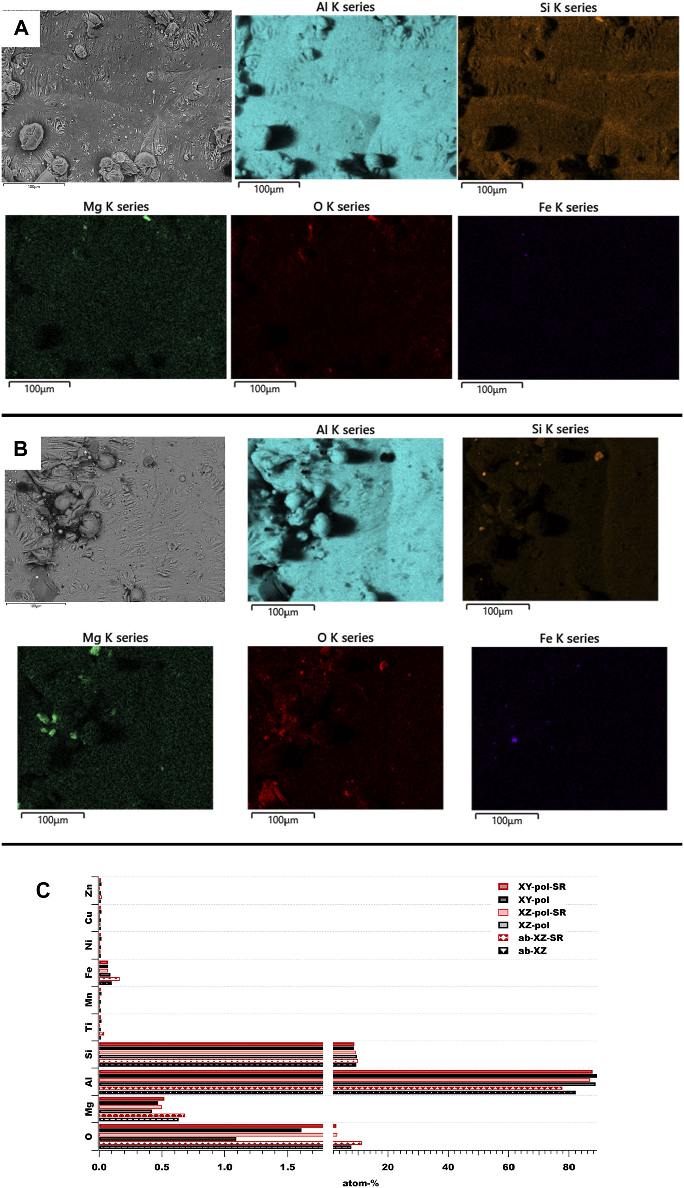
SEM and EDS analysis of as-built surfaces: (A) as-built XZ surface; (B) as-built XZ SR surface; (C) elemental overall contribution of these surfaces.
The PEO surfaces show three main features, which are shown in Figure 2. They can be divided into flat and pancake-like structures, and sponge-like structures, which appear as a network, and volcano-like structures, exhibiting some open porosity. All of these are known to be formed during PEO processes under different conditions (Clyne and Troughton, 2019; Ntomprougkidis, 2020). The pancake-like structure exhibits the highest Al-O-contribution with a low content of Si and other electrolyte elements. They are formed due to micro discharging events, which are filled with fast solidification aluminum oxide. Sponge-like networks contain a high amount of electrolyte elements, such as Na and K. Such structures are linked to the soft-spark regime in the literature (Ntomprougkidis, 2020). The volcano-like structures are also assumed to result from the micro discharging events, but the resulting channels are not filled with further molten oxide. In the case presented here the volcano-like structures exhibit an increased amount of Si. It can be concluded that Si-rich areas near the surface of the substrate material may be the reason for this type of feature.
FIGURE 2
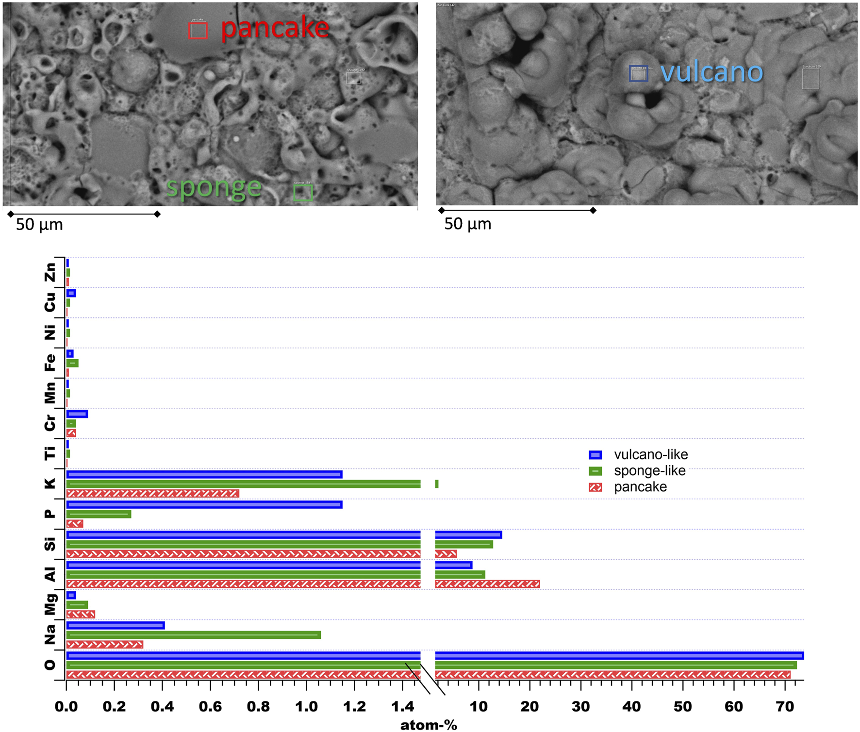
Most prominent features of the applied PEO surfaces with their elemental contents from EDS analysis.
The PEO applied on the as-built surface exhibits a homogeneous distribution of a pancake- and sponge-like structure (see Figure 3A, first row). Without significant change in overall surface roughness (see Table 2), the PEO surface reduces the height of the peak roughness and forms a leveled surface. Although the topography of the stress-relieved samples does not defer from the untreated surfaces, the PEO on the stress relieved surfaces shows a more volcano-like structure. This structure becomes more obvious on the polished stress relieved XZ sample. As mentioned above, the volcano-like structure might be the result of eruption of the molten metal oxide from micro discharge events. Large Si grains may lead to a more intensive eruption, as they are found in the SR surface (see Figure 1B) and were reported to be formed by SR treatment (Cabrini et al., 2018). Furthermore, SR treatment leads to an increased native oxide layer, which is also indicated by the increased oxygen concentrations after the SR process for all samples (see Figure 1C) on the surfaces. This oxide layer requires high breakdown potential and, thus, high energy to be overcome at the beginning of the PEO process. This might result in fast solidification of the molten oxide. In the case of PEO on the XZ-polished samples, there seems to be an orientation of elemental contribution (see EDS mapping in Figure 3 c and d): Here, the Al, O and K appear in vertical lines. From the top view, the PEO structure on the polished XY plane shows a structure that seems to be independent of the SR process (compare Figure 3 e and f). This might be due to the lower difference of the oxygen concentration of the XY-pol (1.6-atom-%) and XY-pol-SR surface (2.9-atom-%) (compare EDS results in Figure 1C). A further reason for the different PEO structures on the different planes (XZ and XY) might be an excessive amount of melting pools that possess more Si grains in the XZ direction.
FIGURE 3
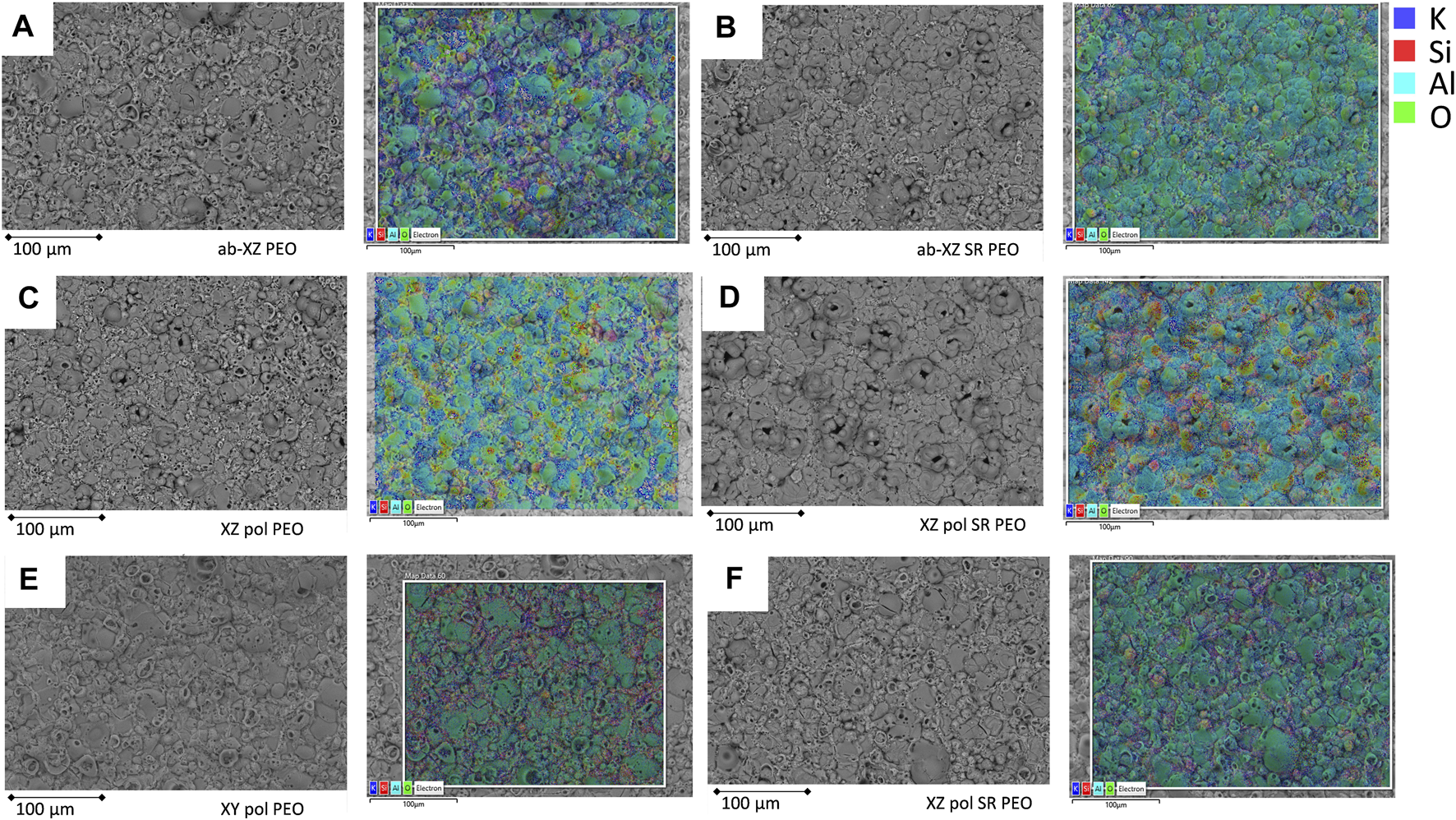
PEO on the different printed surfaces; left: BSE-SEM figure; right: EDS elemental distribution of the same position; (A), (B) XZ-ab PEO; (C), (D) XZ-pol PEO, (E), (F) XY-pol PEO.
The morphology of the PEO surfaces is shown in a cross-sectional view in Figure 4. Most of the samples show a homogeneous dense layer in the middle and inner area of the PEO coating, while the outer layer exhibits coarser structures. For stress-relieved samples, the outer layer shows a distinct area of coarse plates, which corresponds to the volcanic structure discussed above. This effect appears to be most dominant on the XZ-polished SR surface accompanied with the lowest coating thickness. In this case, the increase in oxygen due to the SR process is most dominant by almost a factor of three, whereas in the case of the XZ-ab surface, the oxygen level increases by 45%. This proves the theory that energy, which is necessary to overcome the native oxide layer on the surface (breakdown potential) is missing afterwards to form the PEO layer properly.
FIGURE 4
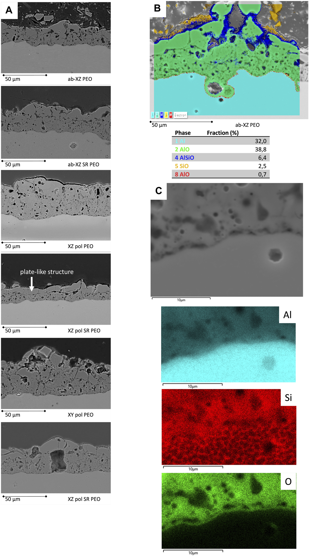
Cross-sectional views of the PEO-coated surfaces; (A) BSE-SEM micrographs of the PEO-coated printed surfaces; (B) PEO enclosed near-surface keyhole pore and its EDS phase analysis; (C) view of the interface of the PEO coating accompanied by the EDS elemental mappings.
The PEO on the polished samples shows a pronounced flat interface; hence, the peak and valley roughness of PEO on polished substrates is lower than that of PEO on unpolished substrates. The surface-near keyhole pores, which are due to the printing process (King et al., 2013), are found to be enclosed by the PEO coating, thereby providing a high level of protection. In Figure 4B, EDS phase analysis shows that the dense aluminum oxide layer protects the surface near keyhole pore. Furthermore, a thin barrier layer (red in color) can be found. Closer to the PEO outer surface, the Si-rich phase appears, and it is completed by the sponge-like structure with a high Si-O-content (yellow). This is in agreement with recent findings for PEO on Al10Si1Mg SLM alloys (Mora-Sanchez et al., 2021). Moreover, all of the coated samples exhibit good adhesion to the substrate within the cross-sectional view. A zoomed in image of an interface region is illustrated in Figure 4C. The oxide thin barrier layer can be identified by EDS mapping, while the Si network of the substrate is also presented.
Mechanical Characterization of the Surfaces
Nanoindentation measurements were performed at both, the substrate material and the applied PEO coatings. In all cases 10 measured curves were taken into account.
In the case of the substrate material the SR treatment led to a reduction of hardness of 20% from 108 HV0.1 to 83 HV0.1 in the case of the XZ plane (see Figure 5, top panel). These values are somewhat lower than reported in (Aboulkhair et al., 2016; Cabrini et al., 2016a; Trevisan et al., 2017), and more comparable to values reported for SR and WQ treatment, whereas the WQ treatment includes an annealing step (Cabrini et al., 2016a). The E-modulus EIT seems to be almost unaffected by the SR treatment and in the rage reported in the literature (Mora-Sanchez et al., 2021). All observed PEO coatings exhibit comparable displacement curves with a clear decrease of depth (lower panel of Figure 5). The mean hardness values for the applied PEO surfaces deviate in the range of 553 HV0.1 and 830 HV0.1, whereas the highest value is measured for the XZ-pol-SR-PEO sample. This is in agreement with the morphological findings shown in Figure 4A and discussed above. The plate-like structure liked to the high amount of molten Al2O3 leads to higher hardness than the sponge-like structure liked to a higher amount of electrolyte containments. This trend also can be observed for EIT values: Those are in all cases somewhat higher for the PEO coatings on the SR-treated substrates as on their untreated counterparts. The higher amount of volcano-like morphological structures of the PEO in the SR-treated cases leads to mechanical properties, which are less ductile than the PEO coatings on the substrates, which did not undergo heat treatment.
FIGURE 5
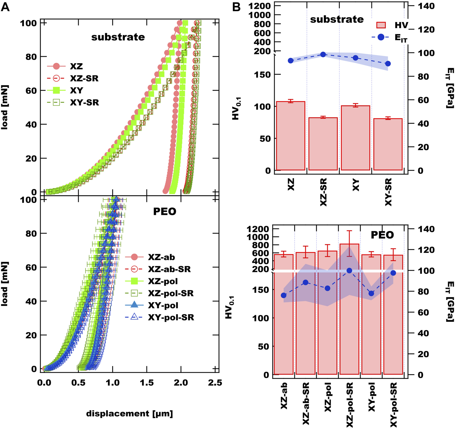
(A) nanoindentation curves of observed substrate materials and PEO coatings; (B) hardness and EIT values of substrate and PEO coatings.
Corrosion Test Results
Electrochemical Impedance Spectroscopy
The EIS measurements of the uncoated AM substrates are shown in Figure 6. The main difference in the initial measurements of the XZ as-built surfaces at room temperature (RT) is the inductive loop, which can be observed in the phase diagram at the low-frequency range for the XZ-ab-SR sample. It can be concluded that the SR process weakens the protective Al-O-layer, and corrosion can take place more easily. Thermal SR heat treatment increases the passive layer thickness and crystallinity of the natural oxide film, as discussed above, but this film is reported to exhibit increased porosity and a micro-cracked structure. As a consequence, the corrosion resistance is low (Vargel, 2020). At increased temperature, the phase diagram exhibits a local maximum at a frequency range between 10° and 10−1 Hz. This is due to diffusion of the electrolyte through corrosion products and into a localized attack. This is in correlation with the deep corrosion effects mentioned in Figure 7. A similar peak can be observed for the increased temperature measurement for the same sample after long-term immersion. A comparable inductive loop is exhibited by the SR state sample of both the polished XZ and XY surfaces, whereas in the case of the XZ-pol-SR sample the long-term immersion does not change this behavior. Here, the corresponding deep localized pittings are also found in the case of the XZ-pol-SR sample (see Figure 7). The cross-sectional findings from Figure 8 confirm this theory. These findings are in agreement with corrosion attack analysis in the literature, where SR heat treatment leads to a discontinuous silicon network (Rubben et al., 2019). The intact Si network, which can be observed in the cross-section of the XZ as-built sample (Figure 8 upper line), leads to a mostly superficial corrosion at the heat affected zones next to the melting pools (Revilla et al., 2020). The corrosion spreads deeper into the sample material (Figure 9). Due to the SR treatment, the Si network is weakened or broken up. As a result, the corrosion is not effectively stopped by the Si network and can spread more broadly, as can be observed for the as-built and also polished SR treated samples in Figure 8.
FIGURE 6

EIS measurements of the uncoated SLM sample surfaces.
FIGURE 7
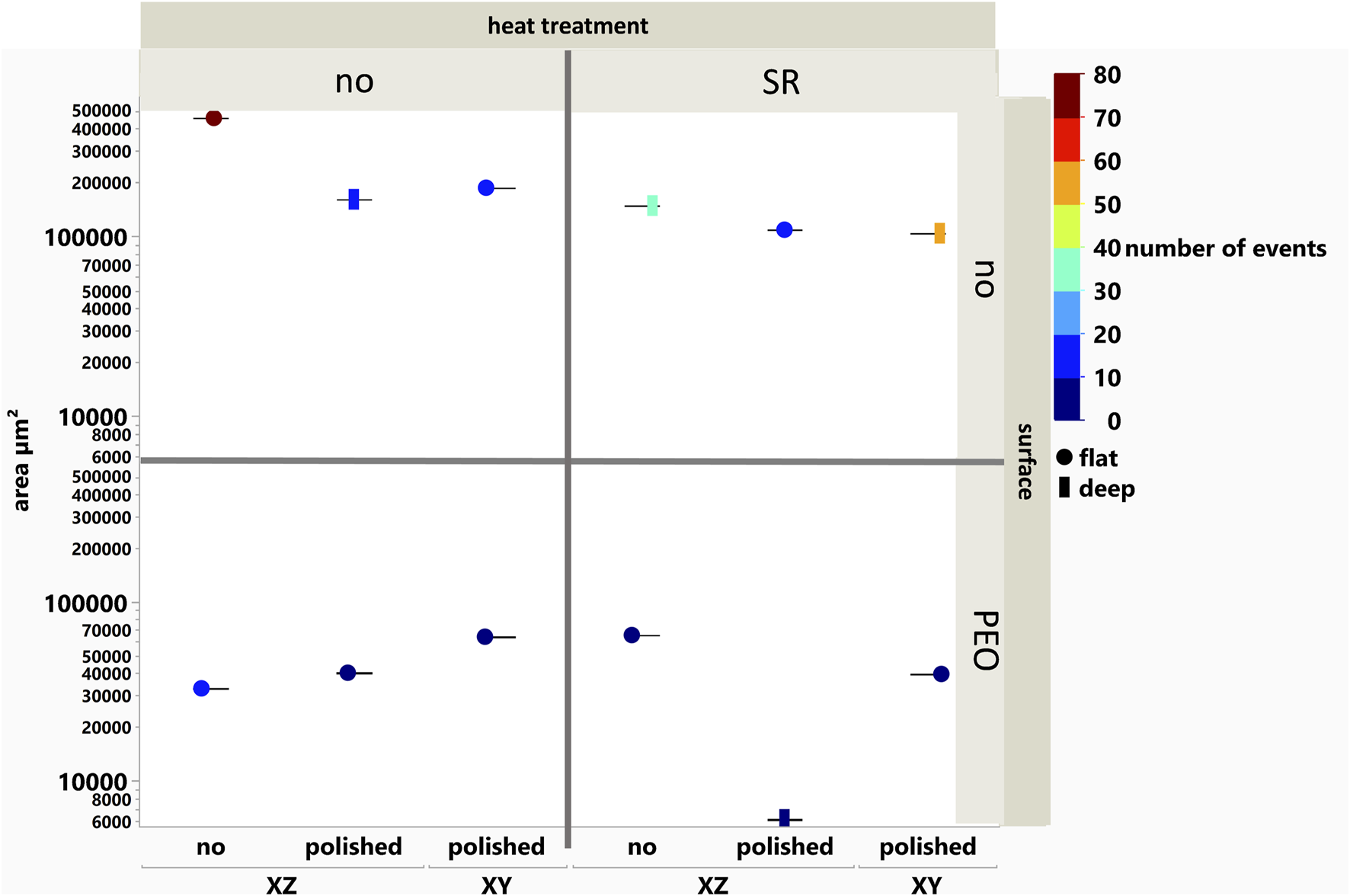
Corroded area in the cross-sections of long-term immersed samples vs the printed direction, mechanical, heat, and chemical surface treatment.
FIGURE 8
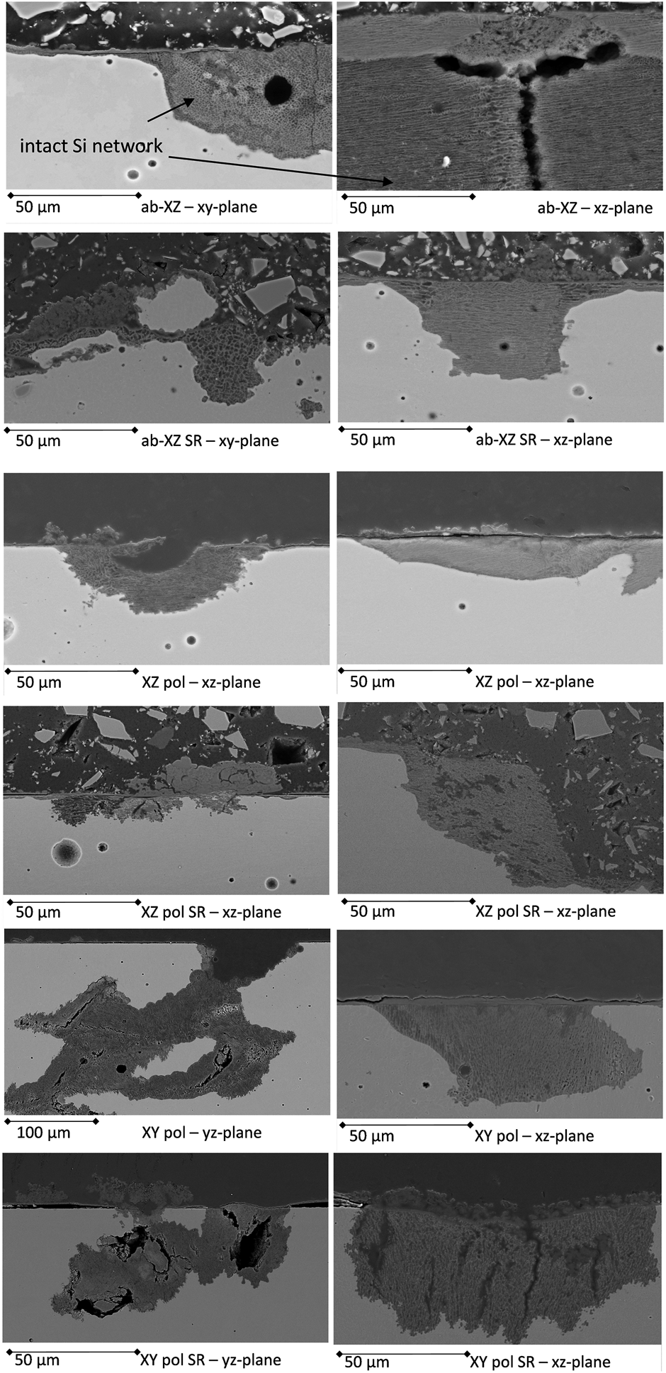
Cross-sections of the corrosion-tested AM surfaces with the most prominent corrosion events observed in different printing directions.
FIGURE 9
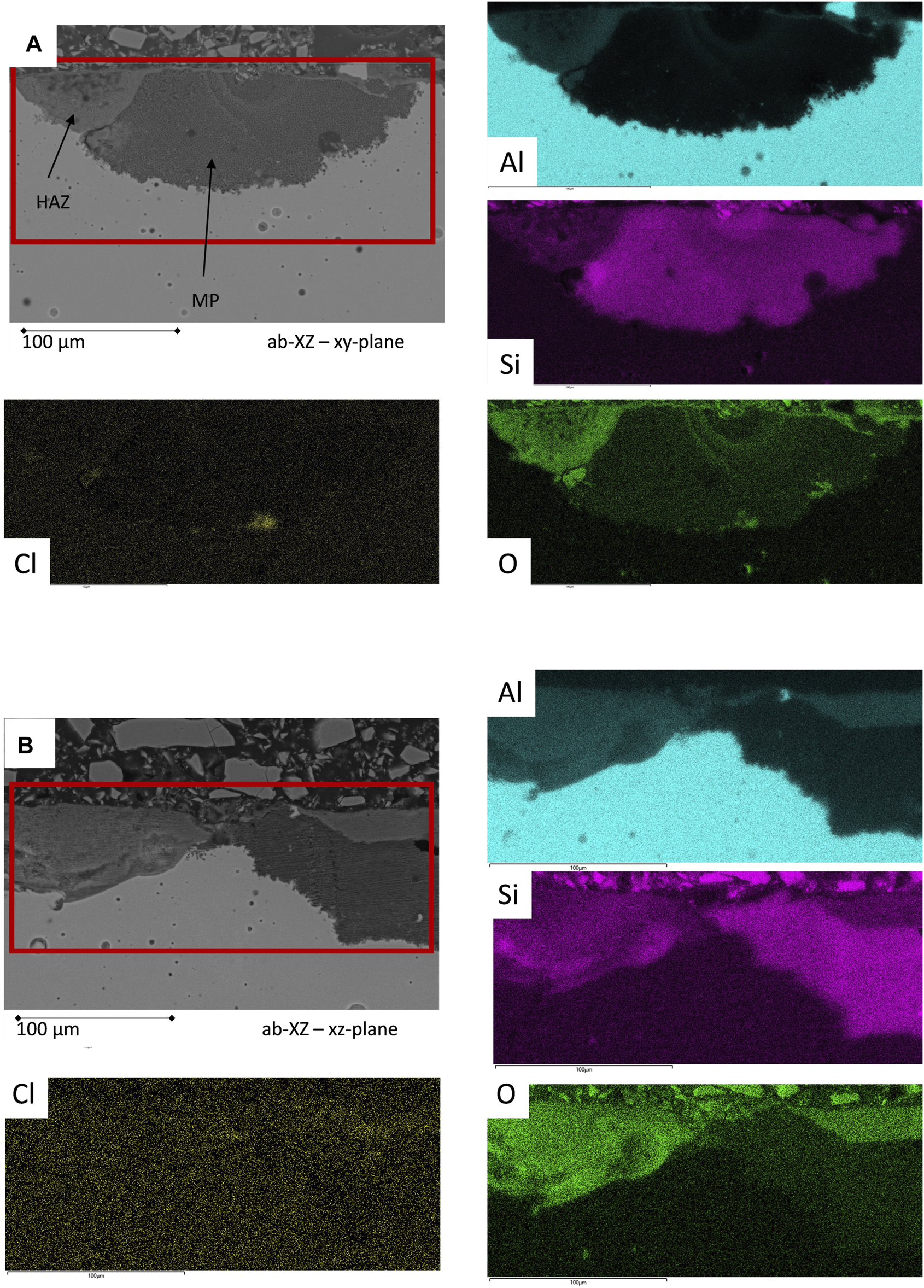
EDS mapping analysis of the corrosion events of the untreated as-built surface after the corrosion test procedure; heat-affected zones (HAZ) show a discontinued Si network, while the melting pool (MP) exhibits an intact Si network.
In Figure 10, the equivalent circuit (EC) model for the bare surfaces and the simulated results are shown. In the EC, Rs represents the resistivity of the electrolyte, whereas Ct is the phase constant element representing the double-layer capacitance of the electrolyte and the rough and non-ideal sample surface. Rct is the value of the charge transfer resistance and, thus, the corrosion resistance, and the Warburg impedance Ws represents charge carrier diffusion through a material (Bajat et al., 2013) and is linked to the diffuse tail in the low frequency range and is typical for corrosion processes, where diffusion of oxygen is involved (Chen et al., 2016; Leon and Aghion, 2017). The fitting values of Rct and Ct over time and at various temperatures are drawn for comparison in the same figure. The Rct values decrease by increased temperature, which indicates a destabilization of the electrode surface at higher temperature (Chen et al., 2016). The as-built surface does not show significant differences in behavior; taking into account the SR heat-treatment, only the Ct value increases at a slower rate for the SR sample. This can be correlated with the difference in the corrosion behavior discussed above. Due to the weakened Si network in the case of SR treatment, the corrosion spreads wider. In terms of the corrosion resistance values, SR treatment does not have an influence, which is in agreement with the literature (Cabrini, Lorenzi, et al., 2016b). The polished surface of the XZ direction exhibits an increase in Ct just after the first measurement at 80°C; afterwards., its values are stable. Both the XZ-pol and XZ-pol-SR sample show wider corrosion attacks accompanied by a lack of an oxide layer (see Figure 8). From the EIS measurements, it could be concluded that polishing leads to an increased corrosion resistance for the surfaces in terms of long-term immersion, which is in agreement with most of the literature (Cabrini et al., 2016a; Cabrini et al., 2016b; Fathi et al., 2018; Revilla et al., 2020). The better corrosion protection of the polished surfaces is assumed to result from the removal of cavities and other surface defects by polishing the AM surfaces. Such defects are assumed to induce localized corrosion (Revilla et al., 2020). However, taking the cross-sectional views of the corrosion effects in Figure 8 into account, it becomes obvious that there are deep corrosion attacks with corrosion products on the surface that lead to the increased impedance values. This proves the theory of (Fathi et al., 2018), who found grounded specimens being attacked selectively deeper than as-built surfaces next to the melting pools along the heat-affected zones. They assumed that during the initial state of immersion into the corrosive medium, the internal microstructural features play a more dominant role (Revilla et al., 2020) than that of the surface defects.
FIGURE 10
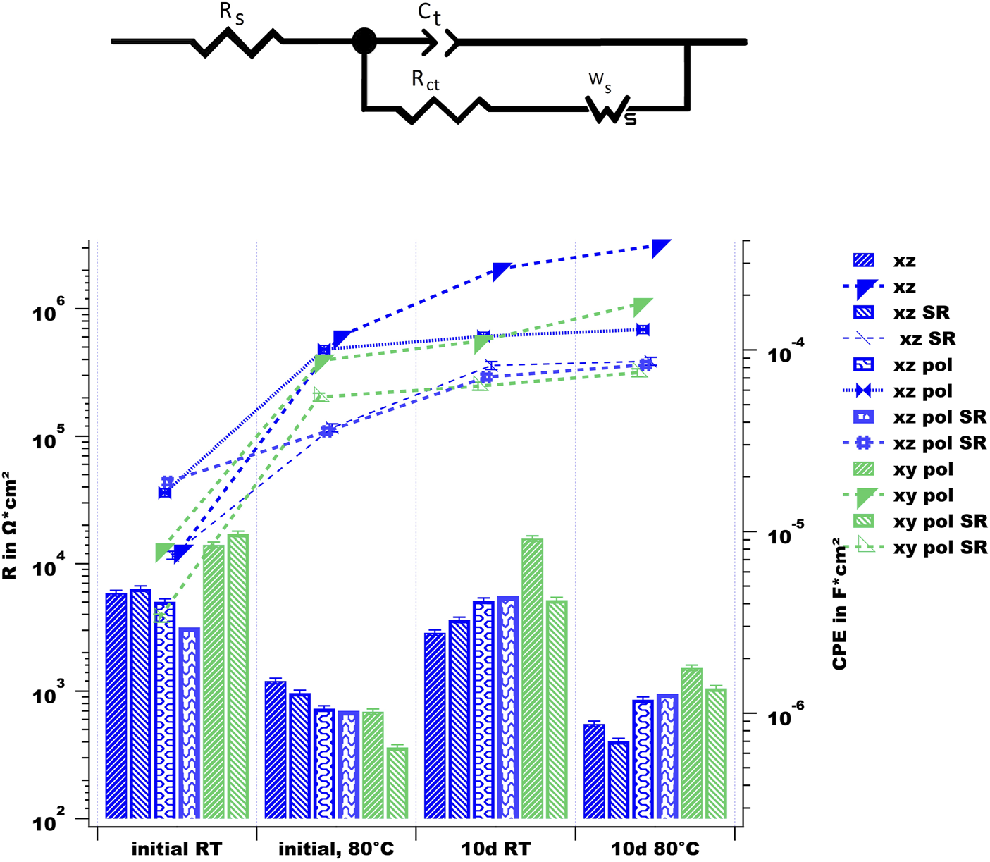
upper part: equivalent circuit model for fitting the EIS results of the uncoated AM sample surfaces; lower part: simulated values using the above EC.
The XY-polished surface shows the highest and most stable values for Rct, and they are in agreement with the low number of pitting events (see Figure 7), whereas SR-treatment shows somewhat decreased values on the system. This could be explained by the fact that in the case of the sample of SR (from Table 2), there appear deeper valleys, leading to better trapping of chloride ions and, as a result, inducing the corrosion acidity in this area. From the impedance measurements the XY direction exhibits a high corrosion resistivity, as reported by (Cabrini et al., 2016b), but the cross-sectional findings in Figure 8 exhibit a contradictory picture with deep corrosion attacks. This is in agreement with some findings in the literature, where this behavior is associated with the depth of the Al/Si cells, which are small and round in the XZ direction and deep in the case of the XY direction (Chen et al., 2018). This can be seen in the corrosion-attacked regions of the cross-sections in Figure 8. It is concluded that the corrosion products can grow and be deposited, leading to cracking of the Si shells (Revilla et al., 2020). In the corrosion attacks observed in this current study this leads to deep undercutting corrosion effects.
In Figure 11, the EIS measurement results for the PEO-treated surfaces are shown in dependance of temperature and long-term immersion. In comparison with the impedance values at the low frequency limit, which is related to the corrosion resistance of the surfaces, all of the PEO-treated surfaces show increased values by two orders of magnitude, thereby providing evidence for high corrosion protection. Furthermore, the phase diagrams show two time constants, which can be linked to a two-layer system of the PEO surface (Bajat et al., 2013; Dehnavi et al., 2015). Figure 12 shows the equivalent circuit model, which was used to interpret the EIS results of the PEO treated surfaces (Toulabifard et al., 2020). Here, the PEO is divided into two layers, a porous outer layer (time-constant at higher frequencies) and a dense inner layer (time-constant at low frequencies). It is commonly accepted that Rin, attributed to the dense inner layer, is significantly responsible for the corrosion protection of PEO coatings (Aliramezani et al., 2017).
FIGURE 11

EIS measurement results of the PEO-coated surfaces.
FIGURE 12
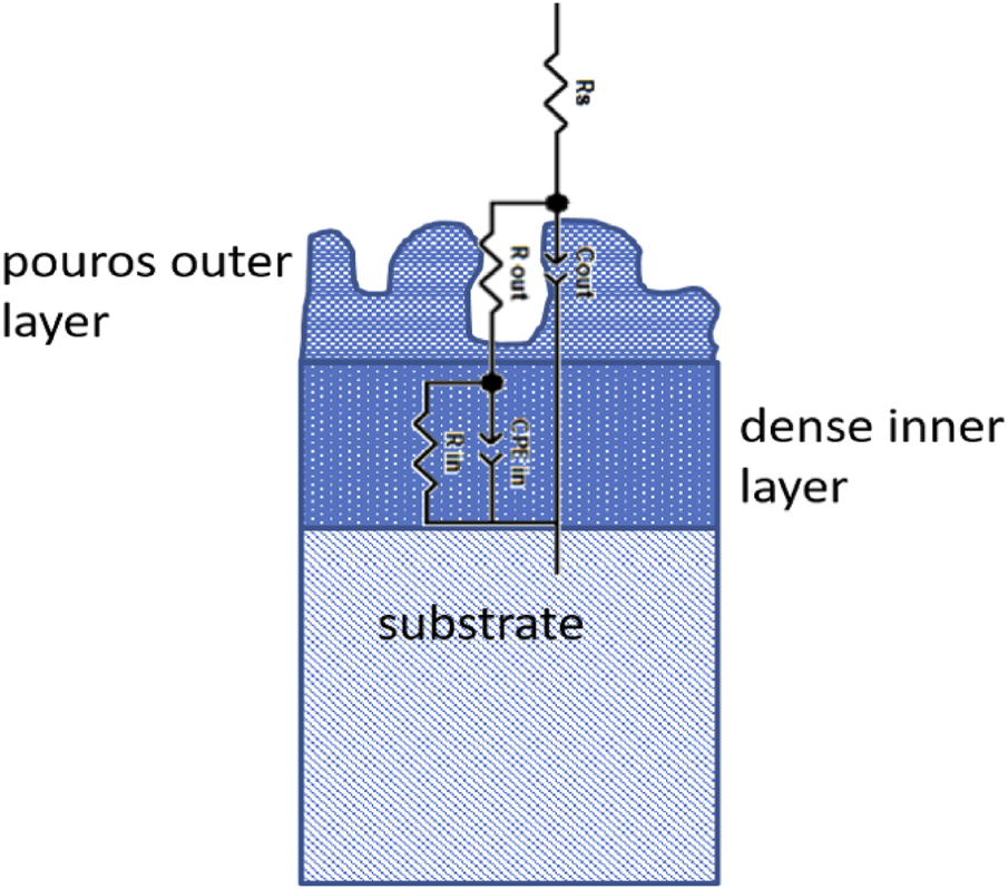
Scheme of equivalent circuit for PEO-treated surfaces
The fitting results are shown in Figure 13. Upon comparing the PEO on the two as-built surfaces in the XZ direction one can conclude that both samples behave similarly at the initial measurements. At room temperature, both samples show high values for the impedance as well as for the fitted resistance values. In both cases, the inner layer shows somewhat higher resistance values, whereas both—those of inner and those of the outer layers - decrease at evaluated temperature. This effect is accompanied by an increase in the capacitance of the outer layer, which suggests the penetration of the electrolyte. After long-term immersion, the XZ-ab-PEO sample shows a decreased value of Rout, whereas the Rin value stays high. The capacitance values for this sample increase after immersion but stay stable for the temperature of 80°C. This is in agreement with the low amount of corrosion attacks found in the cross-sections of this sample (see Figure 7). The corrosion events are small shallow pittings underneath the PEO surface (see Figure 14A). In the case of the SR sample (XZ-ab-SR-PEO), the resistance values for both layers decreases after immersion, whereas the capacitance of the inner layer increases. This might be due to diffusion of the electrolyte into the inner layer after long-term immersion which caused the large and wide pitting corrosion event shown in Figure 14B.
FIGURE 13
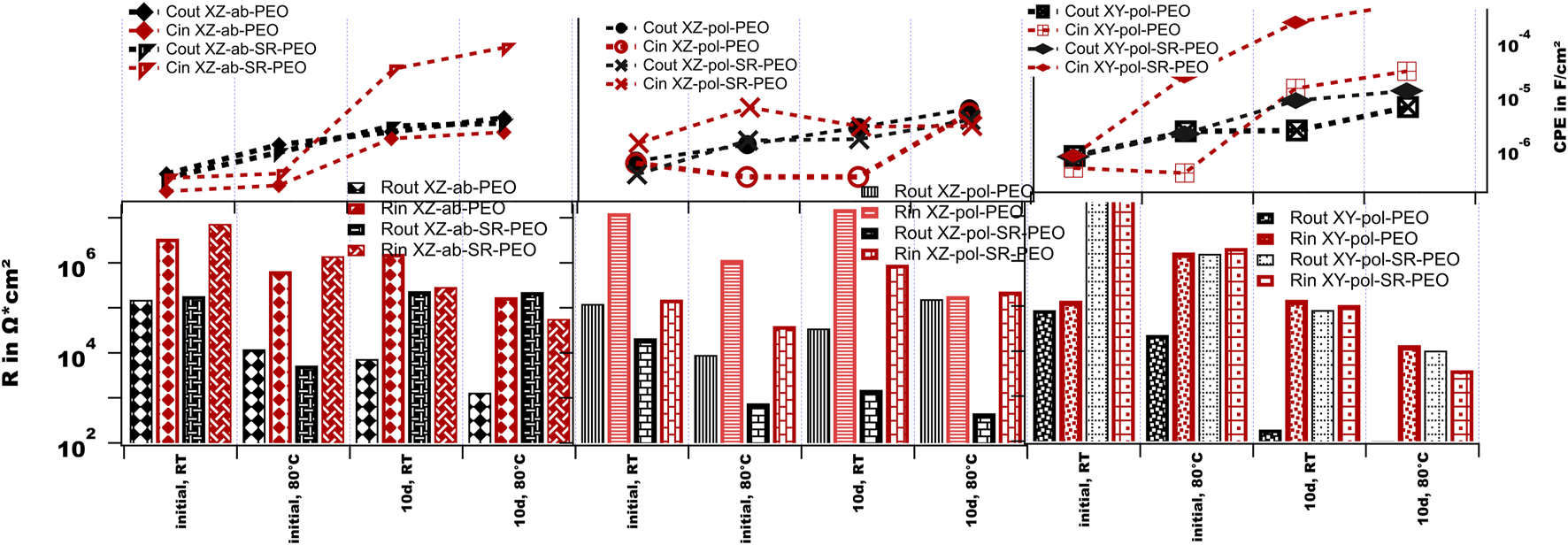
Simulated values for the EIS measurements of the PEO-treated surfaces.
FIGURE 14
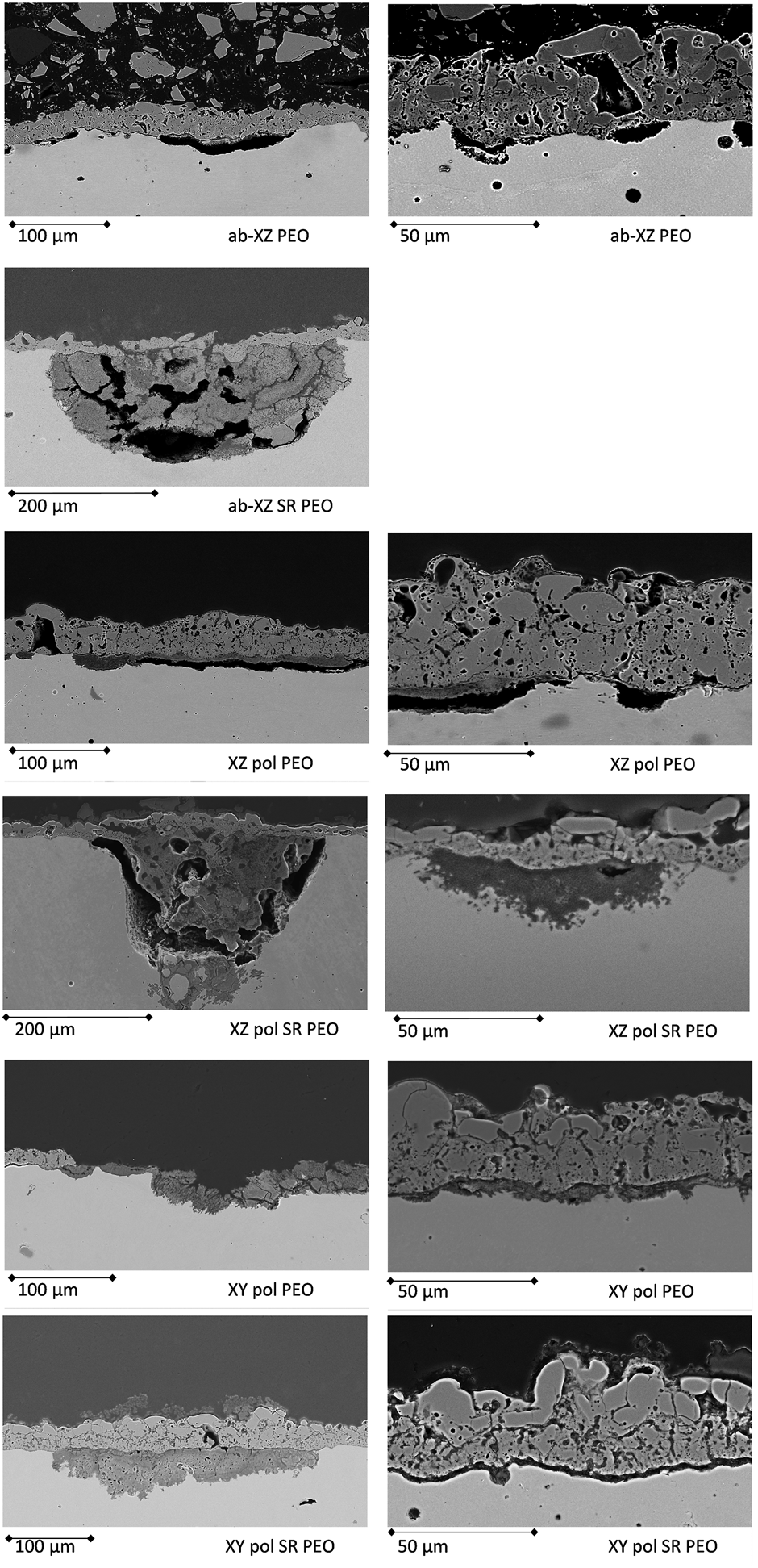
Cross-sections of the corrosion-tested PEO AM surfaces with the most prominent corrosion events.
The polished surface treated with PEO (XZ-pol-PEO) shows at the initial measurement inductive behavior at the interface. This might be evidence of a weakness at the interface of the substrate and the PEO layer. The EIS spectra at a high temperature show comparable drops of the resistivity values. After long-term immersion, the corrosion products may enclose the pores, leading to high values of Rin. By increasing the temperature, the capacitance of the inner layer increases with a decrease in Rin, suggesting dissolution of the inner layer. Taking into account the cross-sectional findings in Figure 14C, this theory can be confirmed, since wide interfacial corrosion is observed. The SR treatment of that surface (XZ-pol-SR-PEO) leads to further weakening of the inner layer. Here, the values in Rin and Rout are low at the initial measurement, accompanied by high increased capacitance of the inner layer, which leads to deep corrosion attacks (see Figure 7). This is due to the previously described morphologies of the PEO surfaces. Since XZ-pol-SR-PEO has a volcano-like structure, this might encourage more corrosion than that in other structures. Furthermore, this layer is thin and shows a loosely bonded solid structure as a top layer (see Figure 4).
In the case of the polished XY direction, the inductive behavior at the interface is most dominant, accompanied by low impedance values. At the high temperature measurement, the inductive behavior disappears and the impedance value for the inner layer increases. It can be concluded that initial corrosion could take place at the interface shortly after the immersion of the sample, whereas the corrosion products block the pores and the inner layer at high temperatures. After long-term immersion, the outer layer shows no protective behavior. Figure 14 shows an event, where the stress of the corrosion products is high enough to collapse the PEO. Wide pitting corrosion can take place here. Such corrosion behavior might be encouraged by the open volcano structure, which is discussed in Figure 2 and Figure 3. The behavior of the capacitance is comparable with the XZ-ab-PEO sample. Here, the areas with the interfacial corrosion are comparable (see the right parts of Figure 14 a, e).
The XY-pol-SR-PEO sample shows the highest impedance values at the initial measurements. This might be due to it possessing the highest coating thickness value (see Table 2). However, the capacitance of the inner layer increases with the high temperature, thereby providing evidence of penetrating electrolyte as shown in Figure 14F (left): corrosion occurs at the interface, and its products can be found in the pores. After long-term immersion, this sample shows the highest increase in capacitance of the inner layer accompanied by the lowest impedance value for the inner layer at high temperatures. Taken into account the corrosion picture (Figure 14F right), this behavior can be explained by a wide and shallow pitting underneath the PEO with corrosion products, which are transferred above the PEO surface.
From the impedance measurements, the PEO-treated as-built surface shows the most stable behavior over time and at various temperatures. SR treatment seems to lead to a weaker corrosion resistance being accompanied by an increase in capacitance of the inner layer, which is related to the solid volcano structure formed by the PEO process on the SR surfaces.
Corrosion Mechanisms
The long-term immersed and electrochemically analyzed surfaces were characterized regarding their corrosion mechanisms by observing their metallographic cross-sections. Then, the observed corrosion events within a cross section were counted (number of events, color bar in Figure 7), and their depth () and width () were measured using an LSM. From these measurements, an accumulated corroded area (y axis in Figure 7) was calculated within the cross-section. Furthermore, an aspect ratio of the events was calculated by . Corrosion types of an aspect ratio of are categorized as “flat” corrosion events (spheres), while those with are categorized as “deep” (rectangular) corrosion events.
It is noteworthy that the as-built surface without any mechanical and heat treatment shows the highest corroded area with the highest number of events, whereas its PEO-treated counterpart shows a huge reduction in the corroded area by a factor of 10 with a reduced amount of corrosion events. This in agreement with the EIS measurements, which show that this PEO-treated sample has the most stable behavior under both conditions of increased temperature and long-term immersion.
In the case of the uncoated surfaces, both the polishing and heat treatment processes lead to a reduction in the overall corroded area measured within the cross-sections, whereas in the case of the XY printing direction, the corrosion events appear to be deep. This is in agreement with the prediction done before by the EIS measurements.
Furthermore, it can be mentioned that the PEO process in all cases leads to a clear reduction in the corroded area and the amount of corrosion effects, whereas the polished, SR-treated surface and polished PEO-treated surface show the lowest values, with the latter being the only PEO system to show “deep” corrosion events. This minimally corroded area can be linked with the high impedance values for this system, while the depth of the corrosion attack can be correlated with the fitted low resistance values for the inner layer and the accompanied high value for the capacitance. The SR process on the as-built surface leads to a highly corroded area in the case of the PEO coating, which is in agreement with the observed EIS measurements.
Figure 8 shows the prominent corrosion events of the uncoated, corrosion-tested surfaces. All the surfaces were cut into two different directions to obtain a full picture of the corrosion paths dependent on the printing directions. In the case of the as-built surfaces, there is a thin oxide layer, which covers the whole corroded surface. Furthermore, the pittings exhibit an elliptical shape, whereas the silicon network is left behind, which means that the chloride ions aggressively attack the α-Aluminum structure, leaving behind the enrichment of the silicon network. The EDS analysis in Figure 9 confirms this assumption, while showing the corrosion taking place along the melting pool borders (Thijs et al., 2013). The residual Si network consists of cages with a diameter of 700–1,500 nm in the case of the as-built sample along the XY direction. The difference in the printing directions can be observed by comparing the two cross-sections. The residual silicon network exhibits an equiaxed rectangular structure along the XY-printing direction, while the XZ-direction exhibits a network of fine, columnar dendritic structures along the Al boundary (Wu et al., 2016). In the literature (Revilla et al., 2016), the Volta potential at the border of the melting pool was found to be higher than in the center of the melting pool. This correlated with the coarse structure in the borders that led to the higher driving force for the galvanic corrosion and induced the corrosion attacks along the borders, where the heat-affected zones (HAZ) exhibited broken Si borders (Revilla et al., 2020). The observed corrosion mechanism is in agreement with (Revilla and Graeve, 2018), who reported the initiation of corrosion at the MPB followed by superficial spreading of the corrosion attack to adjacent zones, including the HAZ. The SR process did not notably change the macrostructure of the melting pools, therefore, the form of corrosion attack is similar to that of the untreated as-built samples but with a higher corroded area. This is in agreement with the weakened Si network discussed above, which is not strong enough to stop the corrosion from spreading. It can be also observed that the corrosion likely took place under the defects of balling phenomena or laser spatter. According to the literature (Simonelli et al., 2015; Aboulkhair et al., 2019), the formation of spatter induced the change in the chemical composition of the laser spatter, whereas the surface of the spatter had more oxide of Si and Mg as a result of the selective oxidation reactions during the SLM process since Mg has high affinity to oxygen and volatile elements. The alteration in the chemical composition could induce the difference potential and galvanic corrosion. Moreover, the creased area around the spatter could retain the electrolyte and promote higher probability for corrosion to take place in this area. This could explain why the vicinity of spatter is vulnerable to corrosion.
In the case of the polished surfaces, the corroded surfaces do not exhibit the previously mentioned thin oxide layer as observed for the as-built surfaces. The wide and shallow pittings are pronounced in the XZ-plane, and corrosion products can be found on the surface. This confirms the findings of (Fathi et al., 2018), who observed higher corrosion protection of the as-built surfaces in comparison with that of the corresponding grinding surfaces. Thus, they assumed that the coverage by the accumulated heavily oxidized powder particles with coarse dendritic structures of the as-built surfaces hinders further oxidation.
In the case of the XY-polished surfaces, the corrosion events are subsurface and undercutting pittings, which are the most likely to result in failure of the structure under mechanical loading. This kind of corrosion may be due to the orientation of the microstructure. In the case of the XY surface, the electrolyte can penetrate the Si network tubes easily, as they are orientated perpendicular to the surface. The growing corrosion products crack the Si network with further progress, leading to wide and deep corrosion attacks (Revilla et al., 2020).
Figure 14 shows the most prominent effects of corrosion observed in the case of the PEO-treated surfaces. Most of the findings are discussed in the EIS measurements section. The main points to be mentioned are that the XY direction cannot be protected as well as the XZ direction by the PEO process applied in this current study. This might be a result of both the PEO morphology and the substrate microstructure underneath the layer. While in the case of the XZ direction, the electrolyte penetrates the PEO coating after long-term immersion, the spread of corrosion in depth is hindered by the fine Si network of the XZ plane without heat treatment. Process adaption should be performed for the XY-printing direction to form more dense inner layers.
After the heat treatment, the formation of broader Si grains in the substrate material and the increased oxide layer influence the formation of the PEO coating by resulting in more volcanoes structures. This volcano structure, which is dominant on the SR surfaces, enables the corrosive electrolyte to quickly penetrate the outer part and, with increased immersion time and temperature, through the inner part of the PEO, reaching the interface and leading to high corrosion, which cannot be efficiently stopped in the substrate material until breakthrough due to the weakened Si network, as is the case for the XZ-ab-SR-PEO sample.
Conclusion
In this study, the corrosion behavior of SLM substrate material was investigated under different surface conditions, and the respective PEO treated surfaces were investigated.
The electrochemical impedance measurements associated with cross-sectional findings led to an overall understanding of the corrosion process of printed SLM AlSi10Mg substrates and the corrosion protection provided by the PEO layers.
All of the uncoated samples were severely attacked by the Cl ions. Here, a high amount of pitting corrosion was found, especially along the border of the melting pools. The defects from the SLM process, such as pores and spatters, stimulated the corrosion of the as-built surfaces. It was confirmed that the SR process on the uncoated samples did not improve the corrosion resistance of the material. Moreover, the SR process led to increased Si grain sizes and an increased native oxide layer, which was porous and simply penetrated by corrosive media.
The corrosion behavior on the polished surfaces exhibited dependence on the printed directions. In the XZ plane, the amount of corrosion attacks decreased in comparison with the as-built surfaces. Wider corrosion effects could be detected, and the observed corrosion effects changed from elliptical to shallow and were wide shapes with corrosion products rather than an oxide layer on the surface. On the other hand, the subsurface and undercutting corrosion along the adjacent melting pool borders occurred in the polished XY plane. This type of corrosion could seriously reduce the structural integrity of AM components.
The PEO surfaces indeed improved the corrosion protection under both conditions, namely, long-term immersion and high temperature. The initial impedance values were around two orders of magnitude higher for the PEO-coated surfaces than for the corresponding untreated ones. After long-term immersion and at increased temperature measurements, the PEO surfaces exhibited a lower reduction in impedance values, which were around 1.five to two orders of magnitude higher than those of the corresponding uncoated surfaces. Furthermore, the measured corroded area in the cross-sections of the samples decreased by an order of magnitude, and a clear reduction in the amount of corrosion events was also observed. Moreover, defects resulting from the SLM process such as keyhole pores were enclosed and protected by the PEO layer. Depending on the surfaces of the substrate, i.e., the printed plane direction, heat treatment, and roughness of the AM component, there were differences in topography, morphology, mechanical properties, and the thickness of the PEO layer. The SR process on the substrate materials led to coarser volcanic-like and less ductile structures of the outer PEO layer accompanied by reduced coating thicknesses that could weaken the corrosion resistance. This difference in PEO morphology might be due to the thick native oxide layer on the SR-treated substrates leading to a high breakdown potential to be overcome at the beginning of the PEO process accompanied by the large Si grains in the substrate material.
The corrosion that took place in the case of PEO on SR-treated surfaces was rather shallow and occurred at the interface of substrate and PEO layer. This was caused by diffusion through the PEO´s pores, which were prominent in the case of SR samples. Considering the results of this study, PEO on the as-built XZ plane surface without heat treatment shows the best corrosion protection. To improve the corrosion protection on the XY plane and other surfaces, the PEO process could be optimized to meet the maximum protection levels.
These results prove that PEO has notable corrosion-protective properties and assures the long-term protection of AM components.
Statements
Data availability statement
The raw data supporting the conclusion of this article will be made available by the authors, without undue reservation.
Author contributions
AB and JZ contributed to conceptualization and methodology of this study. AB validated the results of the experiments. PJ and AB conducted a research and investigation process. JZ provided the laboratory samples. Data curation was conducted by PJ and AB, PJ and AB wrote the initial draft of the paper. AB supervised the research and managed the project administration. All authors contributed to manuscript revision, read, and approved the submitted version.
Acknowledgments
The authors gratefully appreciate the department of Application, Materials and Consulting Additive Manufacturing from TRUMPF Laser-und Systemtechnik GmbH (Address: Johann-Maus-Straße 2 71254 Ditzingen, E-mail: consulting.am@de.trumpf.com) for producing the SLM parts for this research.
Conflict of interest
PJ, JZ, and AB were employed by ELB Eloxalwerk Ludwigsburg Helmut Zerrer GmbH.
Publisher’s note
All claims expressed in this article are solely those of the authors and do not necessarily represent those of their affiliated organizations, or those of the publisher, the editors, and the reviewers. Any product that may be evaluated in this article, or claim that may be made by its manufacturer, is not guaranteed or endorsed by the publisher.
Supplementary material
The Supplementary Material for this article can be found online at: https://www.frontiersin.org/articles/10.3389/fceng.2021.734644/full#supplementary-material
References
1
AboulkhairN. T.MaskeryI.TuckC.AshcroftI.EverittN. M. (2016). The Microstructure and Mechanical Properties of Selectively Laser Melted AlSi10Mg: The Effect of a Conventional T6-like Heat Treatment. Mater. Sci. Eng. A.667, 139–146. 10.1016/j.msea.2016.04.092
2
AboulkhairN. T.SimonelliM.ParryL.AshcroftI.TuckC.HagueR. (2019). 3D Printing of Aluminium Alloys: Additive Manufacturing of Aluminium Alloys Using Selective Laser Melting. Prog. Mater. Sci.106, 100578. 10.1016/j.pmatsci.2019.100578
3
AliramezaniR.RaeissiK.SantamariaM.HakimizadA. (2017). Characterization and Properties of PEO Coatings on 7075 Al alloy Grown in Alkaline Silicate Electrolyte Containing KMnO 4 Additive. Surf. Coat. Tech.329, 250–261. 10.1016/j.surfcoat.2017.09.056
4
ASM International and Handbook Committee (1990). ASM Handbook. Materials Park, OH.
5
BajatJ. B.VasilićR.StojadinovićS.Mišković-StankovićV. (2013). Corrosion Stability of Oxide Coatings Formed by Plasma Electrolytic Oxidation of Aluminum: Optimization of Process Time. CORROSION69, 693–702. 10.5006/0859
6
BertuccioliC.GarzoniA.MartiniC.MorriA.RondelliG. (2019). Plasma Electrolytic Oxidation (PEO) Layers from Silicate/Phosphate Baths on Ti-6Al-4V for Biomedical Components: Influence of Deposition Conditions and Surface Finishing on Dry Sliding Behaviour. Coatings9, 614. 10.3390/coatings9100614
7
BulingA.ZerrerJ. (2019). Increasing the Application fields of Magnesium by Ultraceramic: Corrosion and Wear protection by Plasma Electrolytical Oxidation (PEO) of Mg Alloys. Surf. Coat. Tech.369, 142–155. 10.1016/j.surfcoat.2019.04.025
8
CabriniM.CalignanoF.FinoP.LorenziS.LorussoM.ManfrediD.et al (2018). Corrosion Behavior of Heat-Treated AlSi10Mg Manufactured by Laser Powder Bed Fusion. Materials11, 1051. 10.3390/ma11071051
9
CabriniM.LorenziS.PastoreT.PellegriniS.AmbrosioE. P.CalignanoF.et al (2016a). Effect of Heat Treatment on Corrosion Resistance of DMLS AlSi10Mg alloy. Electrochimica Acta.206, 346–355. 10.1016/j.electacta.2016.04.157
10
CabriniM.LorenziS.PastoreT.PellegriniS.ManfrediD.FinoP.et al (2016b). Evaluation of Corrosion Resistance of Al-10Si-Mg alloy Obtained by Means of Direct Metal Laser Sintering. J. Mater. Process. Tech.231, 326–335. 10.1016/j.jmatprotec.2015.12.033
11
ChenH.ZhangC.JiaD.WellmannD.LiuW. (2020). Corrosion Behaviors of Selective Laser Melted Aluminum Alloys: A Review. Metals10, 102. 10.3390/met10010102
12
ChenX.TianW.LiS.YuM.LiuJ. (2016). Effect of Temperature on Corrosion Behavior of 3003 Aluminum alloy in Ethylene Glycol-Water Solution. Chin. J. Aeronautics.29, 1142–1150. 10.1016/j.cja.2015.12.017
13
ChenY.ZhangJ.GuX.DaiN.QinP.ZhangL.-C. (2018). Distinction of Corrosion Resistance of Selective Laser Melted Al-12Si alloy on Different Planes. J. Alloys Comp.747, 648–658. 10.1016/j.jallcom.2018.03.062
14
ClyneT. W.TroughtonS. C. (2019). A Review of Recent Work on Discharge Characteristics during Plasma Electrolytic Oxidation of Various Metals. Int. Mater. Rev.64, 127–162. 10.1080/09506608.2018.1466492
15
DebRoyT.WeiH. L.ZubackJ. S.MukherjeeT.ElmerJ. W.MilewskiJ. O.et al (2018). Additive Manufacturing of Metallic Components - Process, Structure and Properties. Prog. Mater. Sci.92, 112–224. 10.1016/j.pmatsci.2017.10.001
16
DehnaviV.ShoesmithD. W.LuanB. L.YariM.LiuX. Y.RohaniS. (2015). Corrosion Properties of Plasma Electrolytic Oxidation Coatings on an Aluminium alloy - the Effect of the PEO Process Stage. Mater. Chem. Phys.161, 49–58. 10.1016/j.matchemphys.2015.04.058
17
EiliatH. (2015). Tribological Study on Plasma Electrolytic Oxidation Treatment in Al-Si Alloys for Engine Application. DissertationWindsor, Canada: Univerity of Windsor.
18
FamiyehL.HuangX. (2019). Plasma Electrolytic Oxidation Coatings on Aluminum Alloys: Microstructures, Properties, and Applications. Modern Concepts. Mater. Science.2 (1).
19
FathiP.RafieazadM.MohammadiM.DuanX.NasiriA. M. (2018). “EFFECT OF SURFACE FINISHING PROCEDURES ON CORROSION RESISTANCE OF DMLS-AlSi10Mg_200C ALLOY,” in In EFFECT of SURFACE FINISHING PROCEDURES on CORROSION RESISTANCE of DMLS-AlSi10Mg 200C ALLOY. Editors WellsM.BrochuM. (Westmount, QC: Canadian Institute of Mining Metallurgy & Petroleum).
20
GokuldossP. K. (2013). Selective Laser Melting of Al-12Si. Dresden: Technische Universität Dresden.
21
HerzogD.SeydaV.WyciskE.EmmelmannC. (2016). Additive Manufacturing of Metals. Acta Materialia.117, 371–392. 10.1016/j.actamat.2016.07.019
22
HusseinR. O.NorthwoodD. O.NieX. (2013). The Effect of Processing Parameters and Substrate Composition on the Corrosion Resistance of Plasma Electrolytic Oxidation (PEO) Coated Magnesium Alloys. Surf. Coat. Tech.237, 357–368. 10.1016/j.surfcoat.2013.09.021
23
KingW. E.BarthH. G.CastilloV. M.GibbsJ. W.HahnD.KamathC. (2013). Observation of Keyhole-Mode Laser Melting in Laser Powder-Bed Fusion Additive Manufacturing. J. Mater. Process. Tech.214 (12), 2915–2925.
24
LeonA.AghionE. (2017). Effect of Surface Roughness on Corrosion Fatigue Performance of AlSi10Mg alloy Produced by Selective Laser Melting (SLM). Mater. Characterization.131, 188–194. 10.1016/j.matchar.2017.06.029
25
LiR.LiuJ.ShiY.WangL.JiangW. (2012). Balling Behavior of Stainless Steel and Nickel Powder during Selective Laser Melting Process. Int. J. Adv. Manuf Technol.59, 1025–1035. 10.1007/s00170-011-3566-1
26
ManfrediD.CalignanoF.AmbrosioE. P.KrishnanM.CanaliR.BiaminoS.et al (2013). Direct Metal Laser Sintering: an additive manufacturing technology ready to produce lightweight structural parts for robotic applications. la metallurgia italiana (10).
27
MengeshaG. A.ChuJ. P.LouB.-S.LeeJ.-W. (2020). Corrosion Performance of Plasma Electrolytic Oxidation Grown Oxide Coating on Pure Aluminum: Effect of Borax Concentration. J. Mater. Res. Tech.9, 8766–8779. 10.1016/j.jmrt.2020.06.020
28
MingoB.ArrabalR.MohedanoM.PardoA.MatykinaE. (2017). Corrosion and Wear of PEO Coated AZ91/SiC Composites. Surf. Coat. Tech.309, 1023–1032. 10.1016/j.surfcoat.2016.10.041
29
Mohd YusufS.CutlerS.GaoN. (2019). Review: The Impact of Metal Additive Manufacturing on the Aerospace Industry. Metals9, 1286. 10.3390/met9121286
30
Mora-SanchezH.Del OlmoR.RamsJ.TorresB.MohedanoM.MatykinaE.et al (2021). Hard Anodizing and Plasma Electrolytic Oxidation of an Additively Manufactured Al-Si alloy. Surf. Coat. Tech.420, 127339. 10.1016/j.surfcoat.2021.127339
31
NtomprougkidisV. (2020). Study of the Micro-discharges/Metallic Surfaces Interactions for a Better Understanding of the Growth Mechanisms within the PEO Process. Dissertation. Lorraine, France: UNIVERSITE DE LORRAINE, Département Chimie et Physique des Solides et des Surface.
32
PezzatoL.DabalàM.BrunelliK. (2019). Microstructure and Corrosion Properties of PEO Coatings Produced on AM-Aluminum Alloys. KEM813, 298–303. 10.4028/www.scientific.net/kem.813.298
33
PezzatoL.DabalàM.GrossS.BrunelliK. (2020). Effect of Microstructure and Porosity of AlSi10Mg alloy Produced by Selective Laser Melting on the Corrosion Properties of Plasma Electrolytic Oxidation Coatings. Surf. Coat. Tech.404, 126477. 10.1016/j.surfcoat.2020.126477
34
RafieazadM.MohammadiM.NasiriA. M. (2019). On Microstructure and Early Stage Corrosion Performance of Heat Treated Direct Metal Laser Sintered AlSi10Mg. Addit. Manuf.28, 107–119. 10.1016/j.addma.2019.04.023
35
RevillaR. I.De GraeveI. (2018). Influence of Si Content on the Microstructure and Corrosion Behavior of Additive Manufactured Al-Si Alloys. J. Electrochem. Soc.165, C926–C932. 10.1149/2.0101814jes
36
RevillaR. I.LiangJ.GodetS.De GraeveI. (2016). Local Corrosion Behavior of Additive Manufactured AlSiMg Alloy Assessed by SEM and SKPFM. J. Electrochem. Soc.164, C27–C35. 10.1149/2.0461702jes
37
RevillaR.VerkensD.RubbenT.De GraeveI. (2020). Corrosion and Corrosion Protection of Additively Manufactured Aluminium Alloys-A Critical Review. Materials13, 4804. 10.3390/ma13214804
38
RogovA. B.LyuH.MatthewsA.YerokhinA. (2020). AC Plasma Electrolytic Oxidation of Additively Manufactured and Cast AlSi12 Alloys. Sci. Adv. Mater.399, 126116. 10.1016/j.surfcoat.2020.126116
39
RubbenT.RevillaR. I.De GraeveI. (2019). Influence of Heat Treatments on the Corrosion Mechanism of Additive Manufactured AlSi10Mg. Corrosion Sci.147, 406–415. 10.1016/j.corsci.2018.11.038
40
ShaoL.LiH.JiangB.LiuC.GuX.ChenD. (2018). A Comparative Study of Corrosion Behavior of Hard Anodized and Micro-arc Oxidation Coatings on 7050 Aluminum Alloy. Metals8, 165. 10.3390/met8030165
41
SimonelliM.TuckC.AboulkhairN. T.MaskeryI.AshcroftI.WildmanR. D.et al (2015). A Study on the Laser Spatter and the Oxidation Reactions during Selective Laser Melting of 316L Stainless Steel, Al-Si10-Mg, and Ti-6Al-4V. Metall. Mat Trans. A.46, 3842–3851. 10.1007/s11661-015-2882-8
42
ThijsL.KempenK.KruthJ.-P.van HumbeeckJ. (2013). Fine-structured Aluminium Products with Controllable Texture by Selective Laser Melting of Pre-alloyed AlSi10Mg Powder. Acta Materialia.61, 1809–1819. 10.1016/j.actamat.2012.11.052
43
ToulabifardA.RahmatiM.RaeissiK.HakimizadA.SantamariaM. (2020). The Effect of Electrolytic Solution Composition on the Structure, Corrosion, and Wear Resistance of PEO Coatings on AZ31 Magnesium Alloy. Coatings10, 937. 10.3390/coatings10100937
44
TrevisanF.CalignanoF.LorussoM.PakkanenJ.AversaA.AmbrosioE.et al (2017). On the Selective Laser Melting (SLM) of the AlSi10Mg Alloy: Process, Microstructure, and Mechanical Properties. Materials10, 76. 10.3390/ma10010076
45
VargelC. (2020). Corrosion of Aluminium. Paris, France: Elsevier Science.
46
WuJ.WangX. Q.WangW.AttallahM. M.LorettoM. H. (2016). Microstructure and Strength of Selectively Laser Melted AlSi10Mg. Acta Materialia117, 311–320. 10.1016/j.actamat.2016.07.012
47
YangY.ChenY.ZhangJ.GuX.QinP.DaiN.et al (2018). Improved Corrosion Behavior of Ultrafine-Grained Eutectic Al-12Si alloy Produced by Selective Laser Melting. Mater. Des.146, 239–248. 10.1016/j.matdes.2018.03.025
Summary
Keywords
plasma electrolytic oxidation, corrosion, corrosion protection, additive manucatruing, light metal, aluminium alloy, AlSi10Mg
Citation
Jantimapornkij P, Zerrer J and Buling A (2021) Advanced Corrosion Protection of Additive Manufactured Light Metals by Creating Ceramic SurfaceThrough CERANOD® Plasma Electrolytical Oxidation Process. Front. Chem. Eng. 3:734644. doi: 10.3389/fceng.2021.734644
Received
01 July 2021
Accepted
19 August 2021
Published
09 September 2021
Volume
3 - 2021
Edited by
Luca Pezzato, University of Padua, Italy
Reviewed by
Raul Arrabal, Complutense University of Madrid, Spain
Xiaopeng Lu, Northeastern University, China
Updates
Copyright
© 2021 Jantimapornkij, Zerrer and Buling.
This is an open-access article distributed under the terms of the Creative Commons Attribution License (CC BY). The use, distribution or reproduction in other forums is permitted, provided the original author(s) and the copyright owner(s) are credited and that the original publication in this journal is cited, in accordance with accepted academic practice. No use, distribution or reproduction is permitted which does not comply with these terms.
*Correspondence: Anna Buling, buling@ceranod.de
This article was submitted to Surface and Interface Engineering, a section of the journal Frontiers in Chemical Engineering
Disclaimer
All claims expressed in this article are solely those of the authors and do not necessarily represent those of their affiliated organizations, or those of the publisher, the editors and the reviewers. Any product that may be evaluated in this article or claim that may be made by its manufacturer is not guaranteed or endorsed by the publisher.