 Sreyashi Chakraborty
 Melinda G. Simon
 Alessandro Bellofiore
- Biomedical Engineering Department, San José State University, San Jose, CA, United States
Bileaflet mechanical heart valves (MHV) remain a viable option for aortic valve replacement, particularly for younger patients and patients from low- and middle-income countries and underserved communities. Despite their exceptional durability, MHV recipients are at increased risk of thromboembolic complications. As such, the development of the next generation of MHVs must prioritize improved thromboresistance and aim for independence from anticoagulant therapy. However, innovation in MHV design faces several challenges: strict performance and biocompatibility requirements, limited understanding of the mechanisms underlying MHV thrombosis, and a lack of effective testing methodologies to assess how design variations impact both hemodynamic performance and thrombogenicity of MHVs. This paper reviews the emerging paradigms in MHV design, materials and surface modifications that may inspire the development of a new generation of MHVs for aortic valve replacement. We also discuss challenges and opportunities in developing experimental and numerical approaches to achieve a more comprehensive understanding of MHV flow features and the mechanisms of flow-induced blood clotting.
1 Introduction
Aortic stenosis is a common heart valve disease in which an incomplete opening of the valve reduces flow of oxygenated blood from the heart to the aorta. Figure 1 shows the schematic of an aortic valve with three cusps, a common location for artificial heart valve implantation. Aortic stenosis is more prevalent in elderly people, and is diagnosed in about 12.4% of the US population older than 75 (1). Aortic valve replacement (AVR) is the treatment of choice for severe aortic stenosis, since treatment with pharmaceutical drugs has so far proven ineffective at curbing the progression of the disease (2).
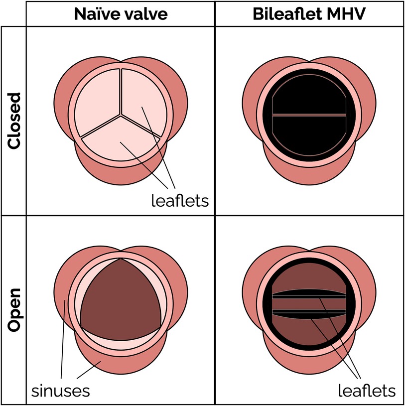
Figure 1. Schematic of a native aortic valve and a bileaflet mechanical heart valve in open and closed positions.
Mechanical heart valves (MHV) (Figure 1) have been available for AVR since the 1960s. MHVs use pyrolytic carbon as the blood-contacting material (over a substrate in stainless steel, graphite or titanium alloys), because it provides good resistance to blood clotting (thromboresistance) (3, 4). A clinical and technological milestone was the introduction of the St. Jude Medical (SJM) bileaflet MHV in 1979. That valve offered exceptional durability combined with suitable hemodynamic performance and thromboresistance. Over the past 20 years, bileaflet MHVs have been replaced as the top choice for AVR by bioprosthetic heart valves (BHV), which can be implanted either surgically or over a catheter. BHV have superior hemodynamic performance and thromboresistance, and so they generally do not rely on lifelong anticoagulant therapy to prevent blood clotting complications (5).
MHV are still clinically preferred, particularly for some groups of patients, due to their superior durability. It is reported that 30% of implanted BHV's require replacement within 15 years, compared to only about 10% of MHVs (6–8). For that reason, current guidelines recommend implanting MHVs in people who are younger than 50 years and BHVs in patients with age more than 70 years (9). Recent studies have suggested an advantage of MHVs in patients between 50 and 70 years (10, 11). In addition to the durability issues, BHVs may cause clinical complications due to calcification (12, 13), and even require anticoagulant therapy in some cases (14, 15). MHVs are also the primary option for pediatric patients who are not eligible for the complex Ross procedure (16, 17), since BHVs have a history of poor outcomes in children and young adults (18, 19). At present, BHVs are more expensive than MHVs and difficult to access for lower-income patients (20). When BHVs fail, usually a transcatheter heart valve is deployed to prevent an open-heart surgery (21). Transcatheter valves have the same durability issues as surgical BHVs, and in addition they are susceptible to stenosis and prosthesis-patient mismatch (6, 22, 23).
Suboptimal thromboresistance of MHVs remains a major concern, especially for those groups where BHVs are not a viable option. Patients with an implanted MHV have an increasing risk of thromboembolism, due to the blood clotting induced by the prosthesis, as well as bleeding, which is a result of the anticoagulant therapy. Several studies have attempted to understand the mechanisms linking flow-induced clotting to specific factors contributing to MHV thrombosis, such as valve designs (24–30), size (31) and materials (32, 33). MHV design is one of the main culprits, because it is significantly different from the naïve aortic valve, thus producing non-physiological blood flow patterns (34–37), which may activate platelets and trigger the clotting cascade.
The goal of this paper is to provide a critical review of the current state and challenges of bileaflet MHVs in the aortic position. Understanding the design and research challenges that have slowed development and innovation for such an important medical device is an essential step for any scientist or engineer pursuing impactful research to pave the way for the next generation of anticoagulant-independent MHVs. In Section 2, we offer a primer on the main fluid-mechanic concepts underlying MHVs, including flow features and metrics relevant to blood clotting, as well as established design paradigms. In Section 3, we review a selection of emerging design concepts, materials and surface treatments that could improve hemodynamic performance and thromboresistance of future MHVs. In Section 4, we discuss experimental and numerical methods that have been developed to characterize MHV flow and flow-induced clotting, and the challenges that so far have prevented a comprehensive understanding of the mechanisms underlying MHV thrombosis. To strike a balance between the breadth and depth of our analysis, we chose to narrow the scope of this review to include primarily bileaflet MHVs implanted in the aortic position. Trileaflet MHVs are also briefly discussed in this review. Readers seeking to learn more can look elsewhere for detailed reviews of bioprosthetic valves (38, 39), transcatheter valves (23, 40, 41), and prosthetic mitral valves (13, 42). Polymeric prosthetic valves are an emerging area of research, and a comprehensive review of materials and recent developments has been published recently (43, 44). Finally, this review primarily focuses on the hemodynamics and thromboresistance aspects of MHV. Valve durability and wear are also important considerations, and are covered in detail in other reviews (45, 46).
2 Bileaflet mechanical heart valves
2.1 Bileaflet valve flow features
Bileaflet MHVs in the aortic position exhibit distinct flow features compared to naïve aortic valves, primarily due to their rigid leaflet designs. During systole, blood flow creates three jets, through the central orifice and two lateral orifices on the sides of the fully open MHV, as illustrated in Figure 2A (side view) and 2C (top view). These jets exhibit high velocity and larger velocity gradients than naïve valves. In addition, depending on the shape and opening angle of the leaflets, wake flow can create non-physiological flow disturbances further downstream of the valve (35, 49). During diastole, MHVs are designed to have some degree of regurgitation (retrograde flow from the aorta back to the left ventricle). Regurgitation is a feature shared with naïve valves, but with some key differences. In bileaflet MHVs, it occurs as leakage flow through the valve hinges and is intended to wash out any blood that may be stagnating in the narrow hinge gaps. As a result, regurgitant flow in MHVs exhibits high-speed jets with abnormally elevated velocity gradients (much higher than in the forward three-jet flow during systole), which have been linked with mechanical shearing of platelets (35, 50, 51). Moreover, areas of flow recirculation can develop behind in the hinge regions, increasing the residence time of platelets and other blood cells, which may lead to thrombus formation. As an example, Dasi et al. reviewed the retrograde flow in the hinge gap of four commercially available valves (SJM standard, CarboMedics, Medtronic Parallel and Medtronic Advantage) and highlighted the recirculation zones that are trapped in this hinge recess (35). The Medtronic Parallel valve hinge design generated a highly convoluted flow compared to streamlined flows in the hinge gaps of the other valves. Eventually, the Medtronic Parallel MHV design was rejected after it showed severe blood clot formation near the valve hinge in clinical trials (35, 52). Figures 2B,D shows location of the hinge jets and flow recirculation during diastole (side and top view, respectively). In the remainder of this section, we will present some specific features of MHV flow that have been linked with potential thrombogenicity. Increasing the hinge gap size has been shown to improve washout of the stagnant flow at the hinges but causes the high velocities of the bulk flow to activate more platelets leading to increased thrombogenicity (50, 53).
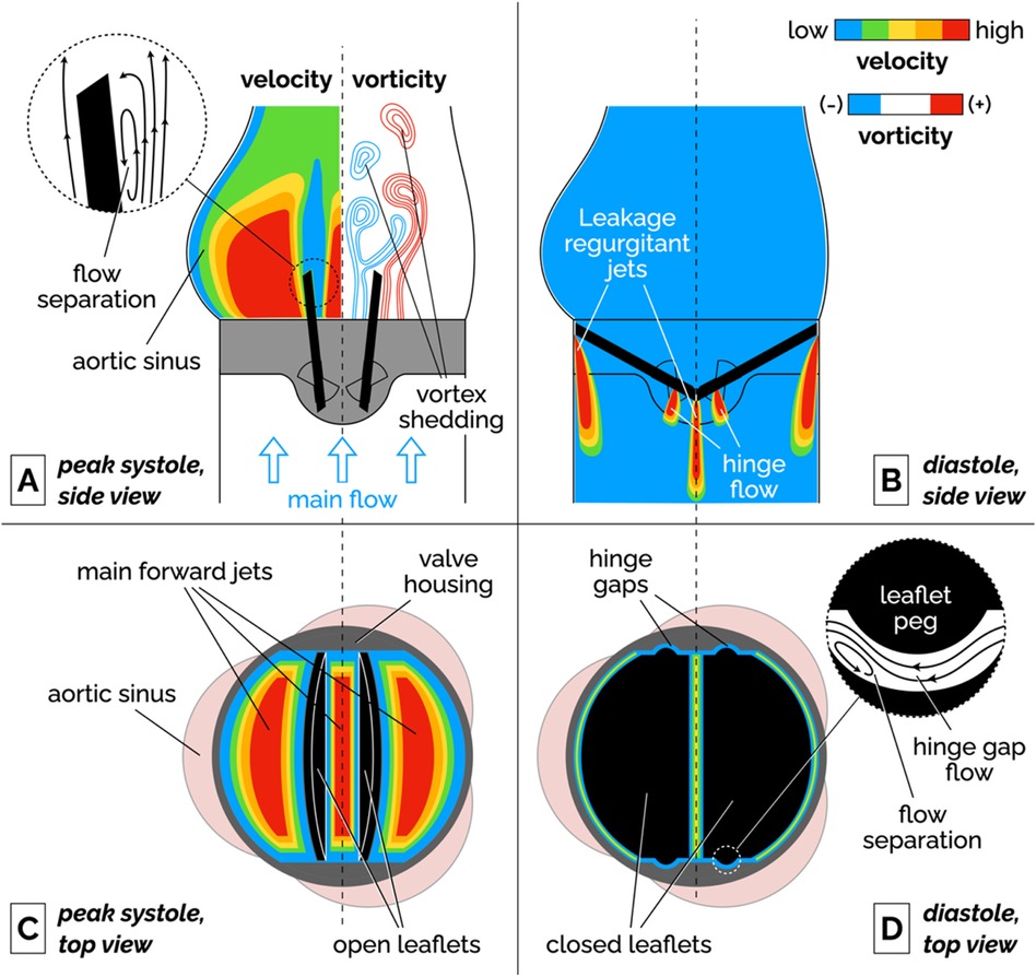
Figure 2. Schematic of the flow features of a bileaflet MHV. (A) Side view of the main forward flow at peak systole. Velocity and vorticity scales are qualitative. The vorticity map illustrates the shedding of pairs of counter-rotating vortices. The inset illustrates the flow separation region on the medial surface of the leaflet. (B) Side view of the regurgitant jets that develop at the edges of the leaflets and in the hinge gaps during diastole. (C) Top view of the valve during peak systolic flow. The fully open leaflets allow the development of three main jets. (D) Top view of the valve during diastole. The inset illustrates the streamlines and flow separation in the hinge gap between the leaflet peg and the butterfly-shaped recess in the valve housing. To keep the illustration simple, the hinge gap flow in the inset is seen from a different point of view than the top view image (right-to-left corresponds to the aorta-to-ventricle orientation).
It is important to point out that the flow features described above have been qualitatively and quantitatively characterized for fully-functioning, pristine MHVs, and so they are representative of ideal valve performance in the early stages after implantation. Leaflet malfunction, which may result in asymmetric leaflet motion, may produce substantially different levels of shear stress and flow stagnation or recirculation, thus accelerating MHV thrombosis (54, 55). Perhaps more importantly, progressive buildup of pannus and blood clots on the leaflets, hinges and housing of the valve may lead to radical changes in the hemodynamic performance of the MHV. Despite the clinical evidence that tissue and clot growth on the valve may occur even just months post implantation (56), in-vitro studies of non-pristine MHVs are a notable absence in the scientific literature.
2.1.1 Flow separation, recirculation and stagnation
Fluid recirculation and stagnation resulting from flow through MHVs is primarily localized in or near the hinge regions, and occurs during diastole. Flow separation and low-shear zones have been observed (48), promoting blood stasis in these regions. These low-shear zones can activate platelets, significantly increasing the chance of thrombosis. The challenge in designing a MHV free of these issues lies in the nature of the flow's complex structure within the hinge, where small-scale turbulence and stagnation coexist. Proper hinge design can reduce thrombogenic potential but is difficult to optimize due to competing constraints on valve performance and durability.
2.1.2 Vortex shedding
Flow separation has also been documented on the medial surface of the leaflet, which leads to adverse pressure gradients and vortex shedding in the wake of the valve. During flow acceleration at the beginning of systole, a pair of counter-rotating vortices develop downstream of the leaflet tip (57, 58). Eventually, these stationary vortices are disrupted by the onset of oscillations, which results in the alternating detaching of vortices from either side of the leaflet. This phenomenon, referred to as vortex shedding, is illustrated in the vorticity plot in Figure 2A. The wake of separated flow interacts with the flow jets creating low pressure zones of separated, pulsatile flow downstream of the leaflet. It has been suggested that platelets that had been activated in high-shear jets may get trapped in the vortices shed from the valve, potentially creating conditions favorable to platelet aggregation and clotting (54, 59, 60).
2.1.3 Intermittent turbulent flow
As the flow decelerates and becomes more unstable during late systole, shed vortices are prone to secondary instabilities that transition into short-lived bursts of turbulent flow (61, 62). Because of the pulsatile nature of the flow, the Reynolds number drops from values above 6,000 at peak systole, to near zero during diastole. These conditions cannot sustain turbulence for the whole heart cycle. The turbulence generates increased viscous dissipation, contributing to higher energy losses. In particular, the interaction between the high-velocity jets and slower recirculating flows can drive flow instabilities, leading to intense localized turbulence, which contrasts with the smoother, less turbulent flow seen in naïve valves. Turbulent flow in MHVs encompasses multiple length scales from ∼25 mm through the valve orifice to ∼100 µm through the valve hinges (35, 63).
2.1.4 Cavitation
Cavitation is the formation of vapor bubbles in a liquid usually at the interface of a moving solid body through the liquid (64, 65). In bileaflet MHVs, cavitation bubbles have been observed after the rapid closure of the valve at the end of systole. This large closing velocity of the leaflets leads to sudden pressure drops (28, 66). If liquid pressure locally drops below vapor pressure at body temperature, the formation of bubbles is possible. These vapor bubbles subsequently collapse, generating high-impact shock waves that can erode the valve material and damage surrounding blood cells (67, 68). Mohammadi et al. showed the acceleration of crack propagation in SJM valve leaflets due to water hammer pressure generated during cavitation (69). Due to rapid valve closure dynamics, the leaflets of Edwards Duromedics valves were subjected to cavitation leading to eventual fracture (70, 71). The distribution of cavitation bubbles depends on the valve geometry and kinematics (64, 68). Overall, the evidence available suggests that controlling cavitation may be important for both reducing the risk of thromboembolism and extending MHV durability (64).
2.2 Bileaflet valve flow metrics
Valve performance must be evaluated following ISO 5840-2, which outlines rigorous requirements for various hemodynamic and structural parameters for surgical valves (mechanical and bioprosthetic) (72). Key metrics include the effective orifice area (EOA) and total regurgitation fraction, which are crucial in assessing the functional efficiency and safety of MHVs. Total regurgitation fraction accounts for all backflow, including both closing volume and leakage volume. While not strictly required by ISO 5840, transvalvular pressure gradients and shear stresses are commonly reported to characterize flow hemodynamic performance and thrombogenic potential of MHVs.
2.2.1 Transvalvular pressure gradient (TPG)
The transvalvular pressure gradient (TPG) is the pressure drop between the ventricular and aortic side of a MHV and represents a measure of the loss of potential energy across the valve. Ideally, TPG should be very low so that the valve does not considerably impede the blood flow; however, ISO 5840-2 does not include a specific requirement for the acceptable range of TPG in MHVs. Compared to a native aortic valve, the rigid material of MHVs create a smaller flow area that increases the pressure drop. Large TPG values are highly undesirable because it means increasing the pressure in the left ventricle during systole, which if sustained may lead to conditions like ventricular hypertrophy and even heart failure. Table 1 reports the TPGs for seven types of commercial MHVs.
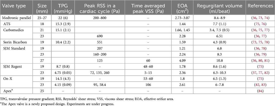
Table 1. Typical values of flow parameters for popular MHVs.
2.2.2 Effective orifice area (EOA)
During forward flow of blood through MHVs, the extent of valve opening is measured by the Effective Orifice Area (EOA) as defined by Equation 1:
where Qrms is the root mean square forward/systolic flow rate, ΔP is the mean pressure across the valve during ejection, and ρ is the density of the test fluid. EOA should be estimated from measurements of pressure and flow in a pulse duplicator simulating realistic physiological conditions. It is important to use the units indicated in Equation 1, since the unit conversion factors are already baked into the “51.6” coefficient (85). MHVs should be designed to make EOA as large as possible, to minimize the pressure drop across the valve for efficient valve function. It is related to valve shape, size and closing mechanism of leaflets. If we consider for example a MHV with nominal size of 27 mm, ISO 5840-2 requires a minimum EOA of 1.70 cm2.
2.2.3 Total regurgitation volume
Total regurgitation volume is the total volume of blood that backflows through the valve during one heart cycle, due to retrograde flow during valve closing and reverse leakage flow through the hinges. Total regurgitation is typically reported as a percentage of the stroke volume. MHV design should seek to minimize the regurgitant volume to maximize the heart's efficiency by maintaining the correct cardiac output of the body (35, 36). For a MHV with nominal size of 27 mm, ISO 5840-2 requires a maximum total regurgitation fraction of 15%. In Table 1, total regurgitation volumes for some commercial valves have been reported as observed in few experiments.
2.2.4 Shear stresses
Shear stresses are important metrics of the hemodynamic performance and thrombogenic potential of MHVs. They have the dimensions of force per unit area (or energy per unit volume), and are related to velocity gradients (velocity per unit length) and fluid viscosity:
In Equation 2, is a generic shear rate, while µ is the apparent viscosity of the fluid. For Newtonian behavior, there is a linear relationship between shear stress τ and shear rate .
Historically, two distinct metrics of shear stress have been reported, sometimes interchangeably even though they are conceptually different. One kind of shear stress can be obtained as in Equation 2, thus representing a measure of the local, instantaneous viscous forces in the fluid (viscous shear stress, or VSS). Alternatively, shear stress can be calculated from the fluctuating components of fluid velocity in turbulent flows. This second type of stress is referred to as Reynolds shear stress (RSS) and represents a measure of the turbulent fluctuations in the flow (82, 86). Both viscous shear stresses (VSS) and RSS have been linked to hemodynamic efficiency and elevated VSS and RSS have been found to contribute to thrombogenicity of MHVs (37, 80, 87).
Hemodynamic efficiency of MHVs decreases when excessive shear stresses develop in the flow. These high shear forces lead to greater viscous energy dissipation, which negatively affects both TPG and EOA. Elevated shear stresses in MHV flow can develop in high-speed jets as well as intermittent bursts of turbulent flow in the wake of the valve. These flow irregularities create inefficiencies, increasing the workload on the heart and affecting overall valve performance.
Shear stresses exceeding normal physiological levels are responsible for platelet activation (an important precursor of blood clotting) or even platelet lysis. The precise mechanisms that relate abnormal shear stresses to clotting are still unclear and have been a major focus of MHV research for decades. It appears that important mechanical factors should include the intensity and duration of platelet exposure to elevated VSS, as well as the occurrence of turbulence.
Experimental measurements of VSS done by various groups with SJM Regent heart valves show a high variability as seen in Table 2. Klusak et al. (80) showed that although mean VSS is much lower (60 Pa) than the threshold for hemolysis (400–800 Pa (35, 36) the instantaneous peak VSS (120 Pa) is above the shear stress criterion for platelet activation (10–100 Pa (35). A similar result was obtained from an earlier numerical study (94). A precise threshold called Hellum's criterion was defined as the product of shear stress and the time duration. Platelets will activate if this value is above 3.5 Pa (35). All these critical values were obtained from in vitro measurements.

Table 2. Design trends found in MHVs in commercial use or in development.
Peak RSS values in different types of MHV are shown in Table 2, although there is some discrepancy in reported measurements of RSS. Earlier studies reported peak RSS during the valve closure mid-diastolic phase (260 Pa for 23 mm SJM Regent valve) (95) while recent work shows peak RSS is observed during peak systole for the same valve (72 Pa) (82).
Interestingly, exceedingly low levels of shear stress are also detrimental, since they may signal the occurrence of regions of flow recirculation or stagnation, where conditions may be favorable to the aggregation (coagulation) of previously activated platelets (96, 97).
Understanding the role of shear stresses in platelet activation and controlling them through MHV design improvements is crucial to achieving independence from anticoagulants. Current MHV designs have been refined to minimize shear stresses, while avoiding development of flow circulation and stagnation regions, as will be discussed in the next section, but clearly there is still much work to do to reduce shear stresses to levels comparable to naïve and bioprosthetic valves.
2.3 Current bileaflet MHV designs
The design of bileaflet MHVs has been stagnant, with one of the most popular models, the St. Jude Medical (SJM) Regent valve being only an incremental refinement of the original model introduced in 1979. Since then, bileaflet MHVs have essentially supplanted all the other mechanical designs (namely ball-and-cage and tilting disc valves). At the same time, their adoption rate has decreased due to the hemodynamically superior bioprosthetic and—more recently—transcatheter tissue valves.
Table 2 summarizes the main design features of selected bileaflet MHVs. The criteria for inclusion in the table were the availability of detailed information on valve design and performance from the open literature and the historical or potential significance of their design. Apart from the Medtronic Parallel valve (discontinued in the 1990s due to unacceptably high levels of clotting in the hinges) and Apex valve (still in development), all the valves in Table 2 are still being implanted in new patients. We did not include any ball-and-cage and tilting disc valves, although they may still be encountered in long-term follow-up patients.
The basic design of bileaflet MHVs features two leaflets (usually D-shaped) hinged to a one-piece housing fitted with an outer suture ring for implantation in the aortic root (98). The SJM Regent valve, a popular version of this design, is illustrated in Figure 3 as an example. It is an incremental evolution than earlier versions of the SJM bileaflet valve, which are now referred to as Masters and Masters HP valve. The main design change from Standard/Masters to Masters HP to Regent was the repositioning of cuff and sewing ring, which helped increase the orifice-to-annulus ratio from 56% (Standard valve) to 72% (Masters HP valve) to 84% (Regent valve), resulting in improved EOA and TPG (99). The hinges follow a peg-and-recess design, with the recess usually located in pockets within the housing, and they allow for the leaflets to open to a maximum angle (relative to the annulus plane) between 60° and 90°. Most MHVs are designed for adult patients, with nominal dimensions between 19 and 31 mm. The only MHV approved for pediatric patients is the 15-mm SJM Masters HP valve.
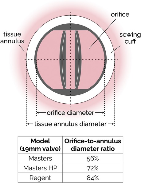
Figure 3. Simplified sketch of the SJM bileaflet valve. In subsequent iterations (from the original Masters design to Masters HP and finally to Regent), the sewing cuff has been shrunk and mover from intra-annular to supra-annular position, resulting in an increase of the orifice-to-annulus diameter ratio. The ratio values reported in the figure are specific to the 19 mm version of the SJM valve.
The Sorin Bicarbon MHVs featured curved leaflets, which was a major departure from the flat design of the SJM valves. In addition, the hinges of the Sorin valves were designed to roll instead of slide (91). Overall, the performance of the two valves was similar, with the Sorin exhibiting higher EOA and smaller regurgitation (73, 75, 78).
The hinge designs of most MHVs include a butterfly shaped recess with the male configuration (Table 2) where the leaflet moves within the hinge recess. The On-X has a smaller recess than the SJM valves. The hinges with the female configuration where the protrusions from the hinge attach to the leaflets offer superior hemodynamics as shown by the newly proposed Apex/iValve design (84, 100).
For most MHVs, the surfaces in contact with blood are made from pyrolytic carbon, a synthetic material developed in the 1950s that exhibits low friction and wear and remarkably good thromboresistance. In most cases, pyrolytic carbon is used as a coating to the more durable materials used for the bulk of leaflets and housing, such as graphite and titanium alloys. Exceptions to these materials are the recent On-X valve, which uses tungsten, and the still-in-development Apex valve, whose prototypes were made either from aluminum or PEEK. PEEK is a rigid polymeric material that has recently been investigated for its good durability and thromboresistance (4, 101).
3 Recent trends in MHV design
The incremental evolution of the popular SJM bileaflet MHV design is illustrative of the limited innovation over the past 50 years. To the best of our understanding, that is partly due to the research challenges that have hampered a better understanding of the mechanisms of flow-induced blood clotting in MHVs (as discussed section 4), and partly due to the rise of alternative bioprosthetic valves (first surgical, and then transcatheter ones), which for a time were expected to completely supplant MHVs for aortic valve replacement. However, MHVs are still the preferred option for specific populations (20, 53, 102), and recent efforts to innovate design, materials and surface treatment of MHVs have revived the hope that they may achieve independence from anticoagulants.
Hinge design, number and curvature of the leaflets and closing dynamics have been the focus of recent research. The On-X aortic bileaflet MHV (Figure 4A) was approved by the US FDA in the early 2000s and marketed with an emphasis on the reduced need for anticoagulation therapy (103). In many ways, the On-X valve represented a departure from the traditional MHV design. The length-to-diameter ratio is closer to a naïve aortic valve. A leaflet opening angle of 90° was the largest yet (Table 2), and combined with a tapered housing inlet, an actuated pivot and leaflet contact at two points, it improved valve hemodynamics and reduced thrombogenicity (93) compared to existing MHVs. One major drawback of the On-X valve is the occurrence of leaflet migration (104–106), which has rarely been observed in other types of MHV.
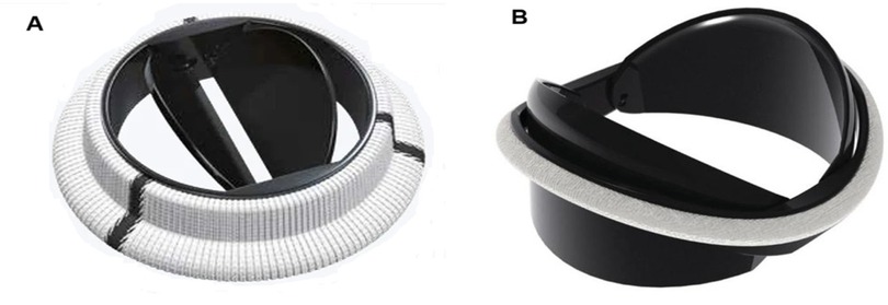
Figure 4. Bileaflet valves in open position (A) On-X valve design. Reproduced with permission from “0n-X@ Aortic Heart Valve” by Artivion, Inc. Used with the Permission of Artivion, Inc. (B) Newly proposed iValve design. Adapted with permission from “Rendered isometric views of the iValve are shown in the A) closed and B) open positions. Both the housing and leaflets are identifiable” by Dylan Goode, Lawrence Scotten, Rolland Siegel and Hadi Mohammadi, licensed under CC BY-NC 4.0.
More recently, a new valve design was proposed with the promise to significantly reduce thrombus formation due to stagnant blood in the hinge region (84). An earlier version of this design, dubbed Apex, (Table 2) featured saddle shaped housing, female portion of butterfly hinges on the leaflet instead of the male portion, and a one-point contact between the leaflets and the housing (84). Subsequently, Mohamadi et al. introduced the iValve MHV as an evolution of their Apex valve (100). The iValve housing has a saddle shape that pushes blood flow towards the hinge ensuring proper washout. The hinge design is different from the Apex design, since the butterfly shaped appendage has been replaced by placing a pie shaped appendage on the housing with a C-shaped open socket on the leaflets.
The curved leaflets of the iValve (Figure 4B) effectively eliminate the lateral jets of traditional bileaflet valves, resulting in a single central jet (107). Based on the limited results reported so far, this major design change may improve hemodynamics and increase the effective orifice area (100). For instance, the closing time and volume of the iValve are improved compared with SJM Regent and ON-X valves (107). The backflow velocity was lower with no fluctuations. The TPG of the iValve is also better compared to the SJM and ON-X valves. While still in development, the Apex/iValve design is an example of innovation that may pave the way for significantly better MHVs.
3.1 Trileaflet MHVs
The concept of a trileaflet mechanical valve is not particularly novel (24–26, 29, 30, 108), but some recent studies have rekindled the interest in this design (109–111). Trileaflet MHVs feature a main central jet, plus three relatively smaller side jets, which reportedly results in smaller velocity gradients compared to bileaflet MHVs (28, 112). The closing mechanism of a trileaflet MHV also appears to create smaller velocity gradients and prevent cavitation, as the swirling vortices during decelerating phase of forward flow initiate closing earlier than bileaflet MHVs (113).
Trileaflet MHVs have been investigated extensively in vitro (27, 109, 110, 113), in silico (28, 114–116) and in animal studies (24–26, 30, 108, 111, 117). Although preclinical trials showed promising results in terms of blood compatibility, no trileaflet MHV has been approved yet for clinical use. Several research groups tested the hemodynamic performance of the Lapeyre-Triflo MHV, manufactured by Triflo Medical Switzerland. The leaflet opening angle of the Lapeyre-Triflo valve is 90 degrees, which matches that of the On-X bileaflet valve and is higher than most commercial MHVs. Reportedly, the increased opening angle reduces disturbance in the forward flow by increasing the EOA for the same valve size (53). In preclinical studies, the thrombogenic potential of the Lapeyre-Triflo valve in calves was comparable to bileaflet MHVs (108, 111). A recent in vivo implantation of a novel 21-mm Lapeyre-Triflo valve in sheep showed promising preliminary results when monitored over 1 year post surgery (117). TPGs were low, regurgitation was minimal, no hemolysis was detected and thrombogenicity was low even without anticoagulation therapy.
3.2 Surface materials, coatings and treatment
Pyrolytic carbon has been the blood-contacting material of choice for MHVs for decades, and is used in many MHVs due to its superior hemocompatibility and favorable mechanical properties (118). For instance, valves made using titanium alloy with a pyrolytic carbon coating provide excellent structural stability as well as decreased thrombogenicity (91). Unfortunately, even the level of thromboresistance provided by pyrolytic carbon is not sufficient to prevent blood clotting. Table 2 lists the materials used for housing, leaflets and coating for few commercially available bileaflet MHVs.
Blood-contacting materials alternative to pyrolytic carbon have been explored. Tetrahedral carbon and ultra nano crystalline diamond have shown the potential to improve wear resistance and chemical resistance (4). Ceramics commonly used for orthopedic and dental implants may provide benefits as a coating material for MHVs, due to their wear resistance and stability (53). Without compromising structural integrity, their use may help reduce leaflet thickness, with a concomitant potential to increase EOA. Carbon-ceramic materials have also been tested, and it has been suggested that they may achieve biocompatibility equivalent to pyrolytic carbon, even with substantially thinner coatings (119, 120).
Other studies have proposed coatings to be added to the pyrolytic carbon surfaces, to further improve thromboresistance (121). Heparin coatings can provide additional protection to clotting, but only in the short term, until the drug is completely eluted into the bloodstream (122–124). Attempts to modify the surface chemical composition by applying a dense titanium oxide coating on pyrolytic carbon (125) or by implanting nitrogen ions to the surface (126) have shown only marginal benefits. Research on the addition of superhydrophobic coatings to pyrolytic carbon has shown some potential. Superhydrophobic coatings trap thin layers of air on valves and thereby decrease the contact area between solid and liquid (127). The small contact areas decrease blood cell adhesion and friction to the pyrolytic carbon surface (32, 127–130). Unfortunately, experimental work has shown mixed results with regard to the efficacy of these coating materials in reducing the likelihood of platelet damage and activation. Bark et al. reported that for a contact angle of 160°, a superhydrophobic spray on a pyrolytic carbon surface eliminated adhesion of platelets and leukocytes. The performance index (PI) of the coated valve improved by 2.5% compared to an uncoated valve (32). Hatoum et al. further investigated the hemodynamic parameters like RSS and instantaneous VSS for a 3D-printed MHV with superhydrophobic coating. The flow metrics that are correlated with platelet damage did not change showing that superhydrophobicity does not improve valve hemodynamics (131).
Finally, various kinds of surface treatment have been proposed to modify its topology to make it more thromboresistant (4). Laser ablation is a cost-effective, environment-friendly, precise and quick technique to create superhydrophobic surfaces on different materials, as the surface roughness can be switched from nanoscale to microscale conveniently (132–134). Laser etching of the pyrolytic carbon of SJM valves (127) (135) produced an increase in the contact angles, which may be conducive to improved hemodynamics, via reduced flow resistance, and thromboresistance. Both hemolysis rate and flow pressure drop reduced further when the superhydrophobic surfaces were laser processed on PyC. The non-equilibrium surface tension in a gradient hydrophobic surface drives droplet movement that can potentially reduce turbulence, mitigating thrombus formation (136).
3.3 Vortex generators
The surface of MHV can be altered by the addition of passive flow control elements, referred to as vortex generators (VGs). VGs are placed on the MHV leaflet surface (137) to delay flow separation and reduce turbulent shear stresses (33). It has been reported that VGs can mitigate the thrombogenic potential of the turbulent jet that develops in the narrowing gap between the two leaflets during closing (138). One downside is the drag penalty associated with VGs (33, 139). PIV and CFD studies have investigated the effect of shape, height, spacing and configuration of VGs, to maximize the hemodynamic benefits while minimizing the excess drag (33, 58, 137, 139, 140). Hatoum et al. showed that a co-rotating equally spaced configuration of rectangular shaped VGs on a 23-mm 3D-printed MHV (Figure 5) offered the optimal performance with improved EOA, minimum TPG and turbulence during pulsatile flow conditions in a mock circulation loop (33, 139). Computational studies by the same author showed that a co-rotating VG configuration can reduce blood cell damage by 4.7% in comparison to a valve without VGs (139). The same study showed that counter-rotating configurations proved to be detrimental as it increased the blood damage by 3.7%. Recent computational studies by Salleh et al. investigated different configurations of triangular shaped VGs on rigid valve leaflets under steady state conditions (141). The authors reported that the inclusion of VGs may have a negative impact on the EOA. In a follow-up study, they used Large Eddy Simulation (LES) to compare the effect of using triangular VGs on an axisymmetric aorta and an anatomic aorta. The anatomic design was found to be more susceptible to thrombosis due to higher peak velocity (2.03 m/s) and WSS (69 Pa) during peak flow phase compared to the axisymmetric one (140).
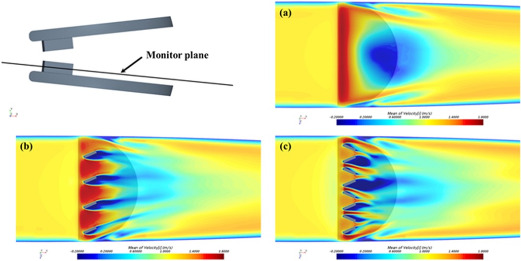
Figure 5. Time-averaged streamwise velocity contours in the monitor plane: (a) control: without VGs; (b) with co-rotating VGs; and (c) with counter-rotating VGs. Reprinted with permission from “Time-averaged streamwise velocity contours in the monitor plane: (a) control: without VGs; (b) with co-rotating VGs; and (c) with counter-rotating VGs” by Zhenyu Wang, Lakshmi Prasad Dasi and Hoda Hatoum, licensed under CC-BY.
The experimental studies with VGs conducted so far have not been able to characterize the local flow between VGs, due to limited spatial resolution. Computational studies are able to resolve those flow features, but the computational cost of time- and space-resolved FSI simulations including non-Newtonian effects of blood near the VGs represents a challenge. In addition, more research is needed to investigate additional combinations of the VG shapes and configurations with moving MHV leaflets, which may also help clarify the effect of VGs on the EOA (141).
4 Research challenges
4.1 Flow characterization techniques
An important aspect of the research on MHVs is the detailed characterization of the flow in the proximity of the valve, especially because MHV flow exhibits abnormal features that are distinct from naïve valve flow. The flow dynamics in the proximity of the valve are crucial to understanding the hemodynamic performance of MHVs, as well as the potential complications that may arise post-implantation, such as thrombosis, hemolysis, or structural valve deterioration. First, MHV flow characterization can be used to identify abnormal features during systole, when abnormal flow patterns such as turbulent jets, flow separation, or regions of high shear stress may develop, and diastole, when regions of stagnation, vortex formation, and reverse flow can emerge. Additionally, MHV flow characterization allows one to directly or indirectly estimate the valve performance metrics discussed in Section 2. These metrics are typically characterized in controlled laboratory environments using mock circulation loops (MCL), also known as pulse duplicators, capable of replicating physiological flow near a test MHV. To assess valve performance according to ISO 5840-2, most MCLs are equipped with pressure and flow sensors, which can capture pointwise or area-averaged data with sufficiently high temporal resolution.
To understand the underlying mechanisms of MHV thrombosis and test the effect of design changes, a more detailed characterization of the flow aims at measuring the velocity field within the flow. Eulerian velocity maps with sufficiently high spatial and temporal resolution can be used to estimate important features, such as local and convective accelerations, shear rates, vorticity, Lagrangian trajectories and coherent structures (47, 55, 142). In addition, if assumptions are made on the mechanical response of the fluid to shearing (e.g., if Newtonian flow behavior is assumed), one can estimate viscous shear stresses and Reynolds shear stresses, as well as the time-dependent mechanical loading experienced by a platelet along a Lagrangian trajectories (143, 144). These estimates have been used in combination with blood damage index (BDI) models to quantify the total damage potentially experienced by a platelet during a single pass through the MHV. There is some evidence that accumulated damage (even below lethal thresholds) may lead to platelet activation and coagulation (145, 146).
Since fluid velocity data are so critical, researchers have used experimental and numerical techniques to measure it. Particle Image Velocimetry (PIV) includes several techniques, all based on the same foundational principles, illustrated in Figure 6. The flow is seeded with neutrally-buoyant scattering or fluorescent particles, a slice or volume of the flow is illuminated (typically with a laser source), images of the illuminated particles are collected in pairs, each pair of images is divided into small interrogation windows and analyzed with cross-correlation algorithms to estimate the particle displacement vector Δx for each interrogation window. The calculated vector Δx/Δt (where Δt is the temporal separation between the two images) represents the velocity of the flow at a specific position in the flow (associated with an interrogation window). PIV is commonly used for the flow characterization of cardiovascular devices, as it allows for time- and space-resolved velocity data. Depending on the specific PIV technique, it is possible to measure 2 or 3 components of fluid velocity either in a planar or a volumetric domain of the flow.
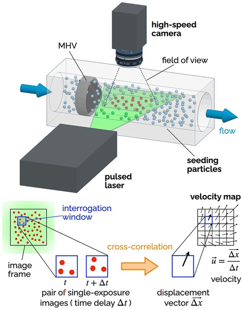
Figure 6. Principles of 2D-2C PIV. A high-speed camera captures images of the seeding particles in the plane illuminated by a thin laser sheet (pulsed). Each image is divided into a grid of interrogation windows. Pairs of single-exposure images (delayed by Δt) are analyzed using cross-correlation algorithms to determine the particle displacement Δx (in the plane of the laser sheet) for each interrogation window. The result is a vector map of the two components of the fluid velocity in the plane of the laser sheet. The delay Δt affects the temporal resolution of the velocity maps, while the distance between the center points of the interrogation window affects the spatial resolution.
Planar two-component (2D-2C) PIV has been extensively used to non-invasively investigate the MHV flow features during in vitro experiments. The recommendations for effectively using PIV to calculate important metrics like residence time, flow velocity and shear stress have been compiled by Raghav et al. (147). 2D-2C PIV was used to quantify velocity fields near valve leaflets under both steady (29, 148) and pulsatile flow conditions (55, 137, 149, 150). Experimental studies with PIV have shed light on the characteristics and relative strength of the three jet-flow observed during systole, when the valve is fully open (55), as well as the role of flow instability developing in the decelerating flow during late systole, which may trigger short burst of turbulent flow in the ascending aorta (47). 2D-2C PIV has also helped characterize the high-speed jets that develop in the narrow gaps of the valve hinges during diastole, when the valve is fully closed (80, 151). All valve designs include some level of hinge clearance, for washout purposes, but hinge flow during diastole is prone to high shear rates, which may lead to platelet activation or even damage.
Because 2D-2C PIV can only measure two components of the velocity in one plane, most studies have focused exclusively on the in-plane velocity in the midplane perpendicular to the rotation axis of the leaflets. Several studies have used more advanced PIV configurations than 2D-2C PIV to overcome the inability to resolve the out-of-plane velocity components (152). Stereoscopic PIV (planar domain, three components of velocity) has allowed for three-dimensional reconstruction of turbulent kinetic energy and vortical structures downstream of MHVs, which for instance has demonstrated the importance of valve orientation when the valve is used in the mitral position (153). Hinge jets with high three-dimensional velocity and turbulence were accurately captured with mechanical and bioprosthetic heart valves in multiple studies exhibiting steady (154) as well as pulsatile flows (152, 155, 156). The limitation of stereo-PIV technique is that the volume of interest is reconstructed from different 2D measurement planes. This requires complex setups to move the PIV system, time-consuming calibration, and post-processing techniques. The introduction of tomographic (157) and holographic PIV (volumetric domain, three components of velocity) enabled capturing all three velocity components simultaneously over a volume of interest. 3D PIV studies investigated the flow topology behind bioprosthetic valves (158) and trileaflet MHVs (159). A recent tomographic PIV study with a MHV in the mitral position analyzed the complete evolution of the vortical structures during a heart cycle and reported lower turbulent kinetic energy levels during mid-diastole and systole compared to tilting-disc valves (160).
Ongoing developments in PIV data processing algorithms, along with the introduction of higher-speed higher-resolution cameras, will lead to even more detailed characterizations of MHV flow dynamics, against which numerical models and clinical data can be compared. However, PIV suffers from some major limitations which are particularly relevant to MHV studies. First and foremost, PIV requires a transparent fluid, which prevents the use of whole blood in this kind of study. Moreover, the need for adequate optical access to the fluid domain under investigation makes it difficult to measure flow near the valve (e.g., hinge flow). To overcome this limitation, researchers must use optically clear models of the aortic root, and in some cases even clear models of the MHV. Glass, acrylic, polycarbonate and silicone elastomers have been used in combination with either water or blood analogues, typically a 40:60 mixture of water and glycerol to replicate blood viscosity (xanthan gum can be added to better model the non-Newtonian behavior of blood). Unfortunately, every combination of solid and fluid listed above results in a mismatch of their refractive index, which creates optical distortion and reduces the accuracy of velocity measurements from PIV (161–163). Another limitation of PIV is that, even with the most advanced cameras and laser sources currently available, resolution may fall short of resolving all the relevant temporal and spatial scales of MHV flow (37, 47).
While PIV is the most common in vitro flow measurement technique for MHV, some earlier studies adopted Laser Doppler Velocimetry (LDV), which is a well-established velocity measurement technique that allows to collect high-quality data from a single point in the fluid domain (51, 164). LDV has some advantages over PIV, namely higher accuracy and temporal resolution, no need for flow seeding, and lower sensitivity to refractive index mismatch (165). However, PIV is superior because of its ability to visualize entire flow fields simultaneously, which makes it possible to capture flow patterns and structures.
As briefly mentioned above, in vitro flow characterization studies commonly rely on test fluids exhibiting Newtonian behavior (water-glycerol mixtures, or just water). These fluids at best replicate the viscosity of whole blood (about 3.5 cP at high shear rates, where the stress-shear rate curve becomes approximately linear), but they fail to replicate both the nature of whole blood (a concentrated suspension of cells) and its non-Newtonian behavior. While it is generally accepted that the rheological behavior of blood in the aorta is largely Newtonian, as shear rates are above 100 s−1, there is some evidence that studies with Newtonian fluids may underestimate the extent of blood cell damage associated with MHV flow (166).
Because of their reliance on laser illumination, PIV and LDV can only be used in in vitro studies. These techniques require precise optical access to the flow field, making them unsuitable for direct use in living organisms, where such access is typically obstructed by biological tissues. However, in the context of this review it is worth mentioning two techniques that can be employed both in vitro and in vivo, providing crucial insights into the hemodynamic performance of MHVs in clinical and research settings: phase-contrast magnetic resonance imaging (PC-MRI), and echocardiography particle image velocimetry (Echo-PIV). PC-MRI is a non-invasive imaging technique that can be used to visualize and quantify blood flow, providing time-resolved three-component velocity data (also known as 4D flow MRI), making it suitable for capturing complex flow patterns and turbulence downstream of MHVs (167, 168). Echo-PIV is an emerging technique that combines the principles of traditional PIV with ultrasound imaging to measure flow velocities in vivo and in vitro (169). In Echo-PIV, microbubbles or contrast agents are introduced into the bloodstream to act as tracer particles, and their motion is tracked using high-frame-rate ultrasound imaging. By analyzing the movement of these particles, Echo-PIV can generate detailed velocity fields similar to those produced by PIV, but in a non-invasive, in vivo context. Echo-PIV is still a relatively new technique, but it holds great promise for bridging the gap between in vitro and in vivo studies of valve performance. In addition, it has the potential to be used for monitoring patients with implanted MHV (170).
4.2 Numerical approaches
Computational fluid dynamics (CFD) have been extensively used to simulate the three-dimensional hemodynamics of MHVs to obtain reproducible, faster, cost-effective insight into the flow physics (50, 171–173). Some of the simpler models simulate MHV flow with fixed leaflets combined with either steady or pulsatile flow conditions, to investigate the triple jet MHV flow dynamics when the leaflets are fully open (36, 171, 174). More refined approaches may prescribe leaflet motion, as derived from experiments, to better simulate MHV flow features with moving leaflets (55, 174).
More comprehensive approaches employ coupled fluid-structure interaction (FSI) algorithms, where leaflet motion is not prescribed but calculated by the model simultaneously with the pulsatile flow. A review by Sotiropulos et al. describes the detailed findings from FSI simulations that investigates the vorticity dynamics, asymmetrical leaflet motion and the effect of implanted valve orientation on MHV hemodynamics (95). Recent advancements in the coupling methods of the fluid and structural domains and developments in individual fluid-structure solvers have enabled numerical simulations of patient-specific hemodynamics across heart valves (175). Abu Bakar et al. (176) validated a FSI model from PIV data to compare velocity and vorticity in a MHV flow domain. Fully coupled two-way FSI studies are ideal for investigating MHV dynamics where fluid and structural domains are solved in parallel (177). Mutual interactions between valve leaflets were accounted for through implicit coupling methods (178, 179). These studies are frequently done using high performance computing (HPC) clusters depending on the model complexity and variability of model parameters.
Grid based methods with fixed grid, moving grid or a combination of both are conventionally used in these solvers. The k-ω shear stress transport (SST) model numerically solves the flow equations and calculates turbulent kinetic energy, turbulent dissipation in addition to velocity and shear stress fields (180, 181).
In a different approach, termed the particle approach, the fluid phase is modeled by the lattice Boltzmann method (LBM) as a distribution of fictitious fluid particles. Results from this approach can be used for Lagrangian tracking of platelet activation or observing the influence of hematocrit on MHV hemodynamics (94, 182, 183). The standard bounce back (SBB) method added to the LBM improves numerical stability for retrieving accurate MHV flow parameters while the external boundary force (EBF) technique of the LBM considers platelets as points with no volume and can help accurately predict platelet activation and blood damage (175).
Overall, alternative computational methods like smooth particle hydrodynamics have shown promise in investigating native heart valves (184, 185) that can extend to study of MHVs. The recent advent of physics-informed neural networks (PINNs) can enable future studies of patient specific MHV hemodynamics and integrate them with multi-modality data to provide a comprehensive model.
PINNs can personalize in-silico models obtained from 4D-MRI cardiac images based on the anatomy and the microdetails of the vasculature (186). The strength of this method is its flexibility to define all flow variables as approximate functions of space and time that can approximately match the boundary conditions and measurement data. PINN studies enable wall shear stress calculation with sparse data where inflow and outflow boundary conditions were not well defined (187). Recent work employed PINN algorithms to investigate flow through a transcatheter aortic valve (188), abdominal aorta (189) and the left ventricle (186). Future implementation of PINN in predicting non-invasive hemodynamic measurements can accelerate patient specific treatment and diagnosis.
4.3 Blood clotting studies
MHV flow characterization in MCLs with transparent blood analogues is useful for comparative studies, as it can provide indirect evidence of thrombogenicity such as shear stresses, residence times and blood damage indices. However, this kind of study alone is not sufficient to investigate all the factors involved in the complex mechanisms of platelet activation and clotting. To establish a link between abnormal MHV flow features and clot formation, whole blood should be used (5, 14, 186).
Early studies of flow-induced blood clotting focused on exposing whole blood to controlled flow conditions. Those studies demonstrated that prolonged exposure of cells to abnormally high-shear stress is responsible for both hemolysis (187, 188), platelet lysis and activation (189). Experiments in steady mean flow have shown that hemolysis levels are significantly higher in turbulent flow than in laminar flow at the same mean shear stress (190). Importantly, those early studies helped identify reference threshold values of viscous shear stress for platelet lysis and activation, and contributed to the idea of sublethal damage accumulation, which may activate platelets over multiple passings through the MHV, eventually leading to coagulation. These findings have been included into empirical models that predict platelet damage from shear stress and residence time data (143, 145, 191). It is important to point out that early studies of flow-induced blood clotting relied on simplified flow systems, such as cone-and-plate rheometers, and thus could not replicate realistic MHV flow.
Some studies have attempted to characterize MHV flow-induced clotting using enzyme-activated milk as the test fluid. This approach is based on some analogies between the mechanisms of clotting of enzyme-activated milk and whole blood (110, 192, 193). Even fewer studies have exposed MHVs to whole blood. One example is the small-volume, biocompatible pulse duplicator developed at Georgia Tech (194). The system was designed to require only 150 ml of whole blood, which could be obtained from a single donor. Results included tests with a 23-mm St. Jude Medical Regent valve in the aortic position. The same system was used for both MHV flow characterization, with PIV and a transparent blood analogue, and coagulation studies, with freshly drawn human blood. Another example is the THIA (Thrombosis Tester Helmholtz Institute), a platform that has gone through several iterations. The latest generation (THIA 3) is a pulse duplicator suitable for evaluating initial clot formation in MHV under realistic anatomic and hemodynamic conditions (195). The ability of THIA 3 to compare the thrombogenic potential of MHVs was validated using a 23-mm St. Jude Medical Regent valve and a test valve (made from polycarbonate urethane) with geometrical and surface features designed to make it highly thrombogenic.
4.4 The need for novel experimental approaches
There are only a few in vitro studies where mechanical heart valves are tested with whole blood under realistic hemodynamic conditions. The main reason is the incompatibility of the commonly used laser-based techniques (PIV, LDV) with opaque fluids such as whole blood. In addition, it is challenging to design a pulse duplicator where the thrombogenic effect of MHV flow can be isolated from other potential sources of blood clotting, such as other foreign surfaces in the loop or mechanical loading caused by other parts such as pumps or resistance valves. One promising solution has been recently proposed by Devos et al. (102). Their MarioHeart system is based on a 155-ml circular loop, housing a MHV, which is accelerated alternately clockwise and counterclockwise. In one phase, the relative motion between the MHV and blood opens the valve, simulating systole; in the other phase, the flow closes the valve, mimicking diastole. This design makes it possible to replicate MHV flow in whole blood while eliminating surface and mechanical elements that could confound the analysis and interpretation of clotting results. The systems just described (102, 194, 195) represent promising solutions to the challenge of in vitro testing of MHVs, and hopefully will inspire more investigators to shed light on the link between MHV detailed flow features and blood clotting.
5 Future directions
The next generation of MHVs needs to deliver on the promise of mitigating thrombogenic risk for the many patients who still receive this kind of valve. This ambitious goal requires innovation in valve design, materials and surface modifications. The review of recent research involving MHVs underscores some of the recent progress made in the last decade, for instance trileaflet MHVs, valve designs with a single central jet like the Apex/iValve concept, or the potential of PEEK as an alternative to pyrolytic carbon. These ideas show that MHVs superior to the traditional bileaflet MHV design are possible. Current developments in 3D printing and rapid prototyping technologies can be used to fabricate and test multiple design variations of bileaflet and trileaflet MHVs. However, prototyping valves coated with pyrolytic carbon (for direct comparison with commercial MHVs in thrombogenicity tests) remains a challenge for many academic laboratories.
The future of MHV thrombosis research also encompasses innovation in testing, across in vitro, in-silico and preclinical platforms. This will allow more accurate, comprehensive and reproducible solutions to investigate flow-induced clotting mechanisms and the effect of novel design paradigms on MHV thromboresistance.
While traditional laser-based techniques such as PIV and LDV provide valuable insights into valve flow dynamics, their limitations with opaque fluids like blood have hindered testing with whole blood. Innovation in in vitro testing means overcoming those limitations and achieving a tighter integration of flow characterization and thrombogenicity testing systems. Currently, the closest integration attainable in vitro is a pulse duplicator that can be run with a clear blood analogue, for detailed flow characterization, and whole blood to study the onset and growth of blood clots. One such example is the MarioHeart system, which promises the ability to simulate realistic conditions with whole blood as the test fluid, although it remains to be proven that it can isolate the thrombogenic potential of MHVs from other confounding factors present in the pulse duplicator.
Whereas a dual-fluid platform suitable for either a clear fluid or whole blood may prove challenging, the second best option would be a twin system with separate clear-fluid MCL and whole-blood thrombogenicity tester. This is a viable approach, provided that the two testers produce matching flow profiles, so the detailed flow data from PIV or LDV can be combined with the clotting data from the whole blood tests.
An alternative approach to experimental research on MHV thrombosis may rely on non-laser-based flow characterization techniques, such as PC-MRI and echo PIV. Because neither method requires optical access to the flow, they can be used with whole blood, allowing to collect detailed flow and clotting data simultaneously. While PC-MRI is only available in few research facilities and the resolution of echo PIV is still limited compared to laser-based PIV, the potential of these techniques for in vitro, preclinical and clinical studies of MHV thrombosis cannot be overstated.
CFD will play an increasingly pivotal role, because it allows for the efficient and systematic exploration of design variations, to identify the most promising features to be subsequently tested in more focused in vitro studies. To accomplish that, there is a need to increase the resolution of multiscale FSI models, while keeping the computational cost reasonably low. Looking further ahead, future numerical approaches will have to go beyond pure fluid dynamics, by integrating mechanochemical models of flow-induced blood clotting (196).
Author contributions
SC: Conceptualization, Writing – original draft, Writing – review & editing. MS: Writing – review & editing. AB: Funding acquisition, Supervision, Writing – original draft, Writing – review & editing.
Funding
The author(s) declare financial support was received for the research, authorship, and/or publication of this article. The NIH award (5SC1HL155056) provided support to the authors to write this review article.
Conflict of interest
The authors declare that the research was conducted in the absence of any commercial or financial relationships that could be construed as a potential conflict of interest.
Publisher's note
All claims expressed in this article are solely those of the authors and do not necessarily represent those of their affiliated organizations, or those of the publisher, the editors and the reviewers. Any product that may be evaluated in this article, or claim that may be made by its manufacturer, is not guaranteed or endorsed by the publisher.
References
1. Wilson JB, Jackson LR, Ugowe FE, Jones T, Yankey GSA, Marts C, et al. Racial and ethnic differences in treatment and outcomes of severe aortic stenosis. JACC: Cardiovascular Interventions. (2020) 13:149–56. doi: 10.1016/j.jcin.2019.08.056
2. énéreux P G, Stone GW, O‘Gara Patrick T, Guillaume M-G, Redfors B, Giustino G, et al. Natural history, diagnostic approaches, and therapeutic strategies for patients with asymptomatic severe aortic stenosis. J Am Coll Cardiol. (2016) 67:2263–88. doi: 10.1016/j.jacc.2016.02.057
3. Bokros JC, Gott VL, La Grange LD, Fadall AM, Vos KD, Ramos MD. Correlations between blood compatibility and heparin adsorptivity for an impermeable isotropic pyrolytic carbon. J Biomed Mater Res. (1969) 3:497–528. doi: 10.1002/jbm.820030311
4. Borna H, Yousefi S, Shirvan AR, Wen C, Nouri A. Surface modification of mechanical heart valves: a review. Eur Polym J. (2024) 205:112726. doi: 10.1016/j.eurpolymj.2023.112726
5. Poli D, Antonucci E, Pengo V, Migliaccio L, Testa S, Lodigiani C, et al. Mechanical prosthetic heart valves: quality of anticoagulation and thromboembolic risk. The observational multicenter PLECTRUM study. Int J Cardiol. (2018) 267:68–73. doi: 10.1016/j.ijcard.2018.04.042
6. Weber A, Noureddine H, Englberger L, Dick F, Gahl B, Aymard T, et al. Ten-year comparison of pericardial tissue valves versus mechanical prostheses for aortic valve replacement in patients younger than 60 years of age. J Thorac Cardiovasc Surg. (2012) 144:1075–83. doi: 10.1016/j.jtcvs.2012.01.024
7. Gaca JG, Clare RM, Rankin JS, Daneshmand MA, Milano CA, Hughes GC, et al. Risk-adjusted survival after tissue versus mechanical aortic valve replacement: a 23-year assessment. J Heart Valve Dis. (2013) 22:810–6.24597402
8. Siddiqui RF, Abraham JR, Butany J. Bioprosthetic heart valves: modes of failure. Histopathology. (2009) 55:135–44. doi: 10.1111/j.1365-2559.2008.03190.x
9. Otto CM, Nishimura RA, Bonow RO, Carabello BA, Erwin JP III, Gentile F, et al. 2020 ACC/AHA guideline for the management of patients with valvular heart disease. J Am Coll Cardiol. (2021) 77:e25–e197. doi: 10.1016/j.jacc.2020.11.018
10. Tasoudis PT, Varvoglis DN, Vitkos E, Mylonas KS, Sá MP, Ikonomidis JS, et al. Mechanical versus bioprosthetic valve for aortic valve replacement: systematic review and meta-analysis of reconstructed individual participant data. Eur J Cardiothorac Surg. (2022) 62:ezac268. doi: 10.1093/ejcts/ezac268
11. Jiang Y, Wang S, Bian J, Chen S, Shao Y. Mechanical versus bioprosthetic aortic valve replacement in middle-aged adults: a systematic review and meta-analysis. J Cardiovasc Dev Dis. (2023) 10:90. doi: 10.3390/jcdd10020090
12. Glaser N, Jackson V, Holzmann MJ, Franco-Cereceda A, Sartipy U. Aortic valve replacement with mechanical vs. Biological prostheses in patients aged 50–69 years. Eur Heart J. (2016) 37:2658–67. doi: 10.1093/eurheartj/ehv580
13. Goldstone AB, Chiu P, Baiocchi M, Lingala B, Patrick WL, Fischbein MP, et al. Mechanical or biologic prostheses for aortic-valve and mitral-valve replacement. N Engl J Med. (2017) 377:1847–57. doi: 10.1056/NEJMoa1613792
14. Chaux A, Gray RJ, Stupka JC, Emken MR, Scotten LN, Siegel R. Anticoagulant independent mechanical heart valves: viable now or still a distant holy grail. Ann Transl Med. (2016) 4:525. doi: 10.21037/atm.2016.12.58
15. Dangas GD, Weitz JI, Giustino G, Makkar R, Mehran R. Prosthetic heart valve thrombosis. J Am Coll Cardiol. (2016) 68:2670–89. doi: 10.1016/j.jacc.2016.09.958
16. David TE. Aortic valve replacement in children and young adults. J Am Coll Cardiol. (2016) 67:2871–3. doi: 10.1016/j.jacc.2016.04.023
17. Sharabiani MT, Dorobantu DM, Mahani AS, Turner M, Peter Tometzki AJ, Angelini GD, et al. Aortic valve replacement and the ross operation in children and young adults. J Am Coll Cardiol. (2016) 67:2858–70. doi: 10.1016/j.jacc.2016.04.021
18. Philip R, Kumar TK, Waller BR, McCoy M, Knott-Craig CJ. Near catastrophic accelerated structural degeneration of the perimount Magna pericardial bioprosthesis in children. Ann Thorac Surg. (2016) 102:308–11. doi: 10.1016/j.athoracsur.2015.09.088
19. Saleeb SF, Newburger JW, Geva T, Baird CW, Gauvreau K, Padera RF, et al. Accelerated degeneration of a bovine pericardial bioprosthetic aortic valve in children and young adults. Circulation. (2014) 130:51–60. doi: 10.1161/CIRCULATIONAHA.114.009835
20. Zilla P, Brink J, Human P, Bezuidenhout D. Prosthetic heart valves: catering for the few. Biomaterials. (2008) 29:385–406. doi: 10.1016/j.biomaterials.2007.09.033
21. Webb JG, Murdoch DJ, Alu MC, Cheung A, Crowley A, Dvir D, et al. 3-year outcomes after valve-in-valve transcatheter aortic valve replacement for degenerated bioprostheses: the PARTNER 2 registry. J Am Coll Cardiol. (2019) 73:2647–55. doi: 10.1016/j.jacc.2019.03.483
22. Head SJ, Celik M, Kappetein AP. Mechanical versus bioprosthetic aortic valve replacement. Eur Heart J. (2017) 38:2183–91. doi: 10.1093/eurheartj/ehx141
23. Ng FC, Abas A, Razak N, Bakar HA. Comparative study of mechanical and transcatheter heart valves for aortic valve replacement. Int J Cardiol. (2021) 345:16. doi: 10.1016/j.ijcard.2021.10.062
24. Gallegos RP, Rivard AL, Suwan PT, Black S, Bertog S, Steinseifer U, et al. In vivo experience with the triflo trileaflet mechanical heart valve. J Heart Valve Dis. (2006) 15:791–9.17152787
25. Gregoric ID, Eya K, Tamez D, Cervera R, Byler D, Conger J, et al. Preclinical hemodynamic assessment of a new trileaflet mechanical valve in the aortic position in a bovine model. J Heart Valve Dis. (2004) 13:254–9.15086265
26. Lapeyre DM, Frazier OH, Conger JL, Macris MP, Perrier P, Reul H, et al. In vivo evaluation of a trileaflet mechanical heart valve. ASAIO J. (1994) 40:M707–13. doi: 10.1097/00002480-199407000-00090
27. Li CP, Chen SF, Lo CW, Lu PC. Turbulence characteristics downstream of a new trileaflet mechanical heart valve. ASAIO J. (2011) 57:188–96. doi: 10.1097/MAT.0b013e318213f9c2
28. Li CP, Lu PC. Numerical comparison of the closing dynamics of a new trileaflet and a bileaflet mechanical aortic heart valve. J Artif Organs. (2012) 15:364–74. doi: 10.1007/s10047-012-0650-8
29. Liu JS, Lu PC, Lo CW, Lai HC, Hwang NH. An experimental study of steady flow patterns of a new trileaflet mechanical aortic valve. ASAIO J. (2005) 51:336–41. doi: 10.1097/01.mat.0000169113.43162.98
30. Sato M, Harasaki H, Wika KE, Soloviev MV, Lee AS. Blood compatibility of a newly developed trileaflet mechanical heart valve. ASAIO J. (2003) 49:117–22. doi: 10.1097/00002480-200301000-00019
31. Yun BM, McElhinney DB, Arjunon S, Mirabella L, Aidun CK, Yoganathan AP. Computational simulations of flow dynamics and blood damage through a bileaflet mechanical heart valve scaled to pediatric size and flow. J Biomech. (2014) 47:3169–77. doi: 10.1016/j.jbiomech.2014.06.018
32. Bark DL, Vahabi H, Bui H, Movafaghi S, Moore B, Kota AK, et al. Hemodynamic performance and thrombogenic properties of a superhydrophobic bileaflet mechanical heart valve. Ann Biomed Eng. (2017) 45:452–63. doi: 10.1007/s10439-016-1618-2
33. Hatoum H, Dasi LP. Reduction of pressure gradient and turbulence using vortex generators in prosthetic heart valves. Ann Biomed Eng. (2019) 47:85–96. doi: 10.1007/s10439-018-02128-6
34. Yin W, Alemu Y, Affeld K, Jesty J, Bluestein D. Flow-induced platelet activation in bileaflet and monoleaflet mechanical heart valves. Ann Biomed Eng. (2004) 32:1058–66. doi: 10.1114/B:ABME.0000036642.21895.3f
35. Dasi LP, Simon HA, Sucosky P, Yoganathan AP. Fluid mechanics of artificial heart valves. Clin Exp Pharmacol Physiol. (2009) 36:225–37. doi: 10.1111/j.1440-1681.2008.05099.x
36. Yoganathan AP, He Z, Casey Jones S. Fluid mechanics of heart valves. Annu Rev Biomed Eng. (2004) 6:331–62. doi: 10.1146/annurev.bioeng.6.040803.140111
37. Ge L, Dasi LP, Sotiropoulos F, Yoganathan AP. Characterization of hemodynamic forces induced by mechanical heart valves: reynolds vs. Viscous stresses. Ann Biomed Eng. (2008) 36:276–97. doi: 10.1007/s10439-007-9411-x
38. Li KYC. Bioprosthetic heart valves: upgrading a 50-year old technology. Front Cardiovasc Med. (2019) 6:1–6. doi: 10.3389/fcvm.2019.00047
39. Tong Q, Cai J, Wang Z, Sun Y, Liang X, Xu Q, et al. Recent advances in the modification and improvement of bioprosthetic heart valves. Small. (2024) 20:2309844. doi: 10.1002/smll.202309844
40. Arora S, Misenheimer JA, Ramaraj R. Transcatheter aortic valve replacement: comprehensive review and present status. Tex Heart Inst J. (2017) 44:29–38. doi: 10.14503/THIJ-16-5852
41. Davidson LJ, Davidson CJ. Transcatheter treatment of valvular heart disease: a review. JAMA. (2021) 325:2480–94. doi: 10.1001/jama.2021.2133
42. Lantz J, Bäck S, Carlhäll C-J, Bolger A, Persson A, Karlsson M, et al. Impact of prosthetic mitral valve orientation on the ventricular flow field: comparison using patient-specific computational fluid dynamics. J Biomech. (2021) 116:110209. doi: 10.1016/j.jbiomech.2020.110209
43. Singh SK, Kachel M, Castillero E, Xue Y, Kalfa D, Ferrari G, et al. Polymeric prosthetic heart valves: a review of current technologies and future directions. Front Cardiovasc Med. (2023) 10:1137827. doi: 10.3389/fcvm.2023.1137827
44. Rezvova MA, Klyshnikov KY, Gritskevich AA, Ovcharenko EA. Polymeric heart valves will displace mechanical and tissue heart valves: a new era for the medical devices. Int J Mol Sci. (2023) 24:3963. doi: 10.3390/ijms24043963
45. Casenghi M, Popolo Rubbio A, Menicanti L, Bedogni F, Testa L. Durability of surgical and transcatheter aortic bioprostheses: a review of the literature. Cardiovasc Revasc Med. (2022) 42:161–70. doi: 10.1016/j.carrev.2022.03.006
46. Sathananthan J, Hensey M, Landes U, Alkhodair A, Saiduddin A, Sellers S, et al. Long-term durability of transcatheter heart valves: insights from bench testing to 25 years. JACC Cardiovasc Interv. (2020) 13:235–49. doi: 10.1016/j.jcin.2019.07.049
47. Bellofiore A, Donohue EM, Quinlan NJ. Scale-up of an unsteady flow field for enhanced spatial and temporal resolution of PIV measurements: application to leaflet wake flow in a mechanical heart valve. Exp Fluids. (2011) 51:161–76. doi: 10.1007/s00348-010-1038-2
48. Klusak E, Quinlan NJ. High-resolution measurements of leakage flow inside the hinge of a large-scale bileaflet mechanical heart valve hinge model. Cardiovasc Eng Tech. (2019) 10:469–81. doi: 10.1007/s13239-019-00423-4
49. Wang J, Gao Q, Wei R, Wang J. Experimental study on the effect of an artificial cardiac valve on the left ventricular flow. Exp Fluids. (2017) 58:126. doi: 10.1007/s00348-017-2409-8
50. Hedayat M, Borazjani I. Comparison of platelet activation through hinge vs bulk flow in bileaflet mechanical heart valves. J Biomech. (2019) 83:280–90. doi: 10.1016/j.jbiomech.2018.12.003
51. Herbertson LH, Deutsch S, Manning KB. Near valve flows and potential blood damage during closure of a bileaflet mechanical heart valve. J Biomech Eng. (2011) 133:094507. doi: 10.1115/1.4005167
52. Bodnar E. The medtronic parallel valve and the lessons learned. J Heart Valve Dis. (1996) 5:572–3.8953433
53. Wium E, Jordaan CJ, Botes L, Smit FE. Alternative mechanical heart valves for the developing world. Asian Cardiovasc Thorac Ann. (2020) 28:431–43. doi: 10.1177/0218492319891255
54. Khalili F, Gamage PPT, Sandler RH, Mansy HA. Adverse hemodynamic conditions associated with mechanical heart valve leaflet immobility. Bioengineering (Basel). (2018) 5:1–6. doi: 10.3390/bioengineering5030074
55. Dasi LP, Ge L, Simon HA, Sotiropoulos F, Yoganathan AP. Vorticity dynamics of a bileaflet mechanical heart valve in an axisymmetric aorta. Phys Fluids. (2007) 19:067105. doi: 10.1063/1.2743261
56. Edmunds LH. Thrombotic and bleeding complications of prosthetic heart valves. Ann Thorac Surg. (1987) 44:430–45. doi: 10.1016/S0003-4975(10)63816-7
57. Li C-P, Chen S-F, Lo C-W, Lu P-C. Role of vortices in cavitation formation in the flow at the closure of a bileaflet mitral mechanical heart valve. J Artif Organs. (2012) 15:57–64. doi: 10.1007/s10047-011-0612-6
58. Salleh NM, Zakaria MS, Abd Latif MJ. CFD Simulation for reduction thrombosis in bileaflet mechanical heart valve using vortex generators. J Eng Sci Technol. (2021) 16:2736–47. https://jestec.taylors.edu.my/Vol%2016%20issue%203%20June%202021/16_3_60.pdf
59. Xu X, Liu T, Li C, Zhu L, Li S. A numerical analysis of pressure pulsation characteristics induced by unsteady blood flow in a bileaflet mechanical heart valve. Processes. (2019) 7:232. doi: 10.3390/pr7040232
60. Bluestein D, Rambod E, Gharib M. Vortex shedding as a mechanism for free emboli formation in mechanical heart valves. J Biomech Eng. (2000) 122:125–34. doi: 10.1115/1.429634
61. Hussain AF. Coherent structures—reality and myth. Physics Fluids. (1983) 26:2816–50. doi: 10.1063/1.864048
62. Hussain AF. Coherent structures and turbulence. J Fluid Mech. (1986) 173:303–56. doi: 10.1017/S0022112086001192
63. Nguyen V-T, Kuan YH, Chen P-Y, Ge L, Sotiropoulos F, Yoganathan AP, et al. Experimentally validated hemodynamics simulations of mechanical heart valves in three dimensions. Cardiovasc Eng Technol. (2012) 3:88–100. doi: 10.1007/s13239-011-0077-z
64. Qian J, Gao Z, Hou C, Jin Z. A comprehensive review of cavitation in valves: mechanical heart valves and control valves. Bio-Design Manufact. (2019) 2:119–36. doi: 10.1007/s42242-019-00040-z
65. Lu L, Xie S, Yin Y, Ryu S. Experimental and numerical analysis on the surge instability characteristics of the vortex flow produced large vapor cavity in u-shape notch spool valve. Int J Heat Mass Transfer. (2020) 146:118882. doi: 10.1016/j.ijheatmasstransfer.2019.118882
66. Lee H, Homma A, Taenaka Y. Hydrodynamic characteristics of bileaflet mechanical heart valves in an artificial heart: cavitation and closing velocity. Artif Organs. (2007) 31:532–7. doi: 10.1111/j.1525-1594.2007.00419.x
67. Li W, Gao Z, Jin Z, Qian J. Transient study of flow and cavitation inside a bileaflet mechanical heart valve. Appl Sci. (2020) 10:2548. doi: 10.3390/app10072548
68. Johansen P, Andersen TS, Hasenkam JM, Nygaard H, Paulsen PK. Mechanical heart valve cavitation in patients with bileaflet valves. 2014 36th Annual International Conference of the IEEE Engineering in Medicine and Biology Society (2014). p. 5655–8. doi: 10.1109/EMBC.2014.6944910
69. Mohammadi H, Klassen RJ, Wan W-K. A finite element model on effects of impact load and cavitation on fatigue crack propagation in mechanical bileaflet aortic heart valve. Proc Inst Mech Eng H. (2008) 222:1115–25. doi: 10.1243/09544119JEIM432
70. Klepetko W, Moritz A, Mlczoch J, Schurawitzki H, Domanig E, Wolner E. Leaflet fracture in edwards-duromedics bileaflet valves. J Thorac Cardiovasc Surg. (1989) 97:90–4. doi: 10.1016/S0022-5223(19)35130-X
71. Johansen P. Mechanical heart valve cavitation. Expert Rev Med Devices. (2004) 1:95–104. doi: 10.1586/17434440.1.1.95
72. ISO 5840-2:2021. In: ISO [Internet]. Available online at: https://www.iso.org/standard/77034.html (cited September 30 2024).
73. Suh YJ, Kim YJ, Hong YJ, Lee H-J, Hur J, Im DJ, et al. Measurement of opening and closing angles of aortic valve prostheses in vivo using dual-source computed tomography: comparison with those of manufacturers’ in 10 different types. Korean J Radiol. (2015) 16:1012–23. doi: 10.3348/kjr.2015.16.5.1012
74. Celiento M, Ravenni G, Milano AD, Pratali S, Scioti G, Nardi C, et al. Aortic valve replacement with the medtronic mosaic bioprosthesis: a 13-year follow-up. Ann Thorac Surg. (2012) 93:510–5. doi: 10.1016/j.athoracsur.2011.10.062
75. Bottio T, Caprili L, Casarotto D, Gerosa G. Small aortic annulus: the hydrodynamic performances of 5 commercially available bileaflet mechanical valves. J Thorac Cardiovasc Surg. (2004) 128:457–62. doi: 10.1016/j.jtcvs.2004.03.021
76. Dumont K, Vierendeels J, Kaminsky R, Van Nooten G, Verdonck P, Bluestein D. Comparison of the hemodynamic and thrombogenic performance of two bileaflet mechanical heart valves using a CFD/FSI model. J Biomech Eng. (2007) 129:558–65. doi: 10.1115/1.2746378
77. Simon HA, Leo HL, Carberry J, Yoganathan AP. Comparison of the hinge flow fields of two bileaflet mechanical heart valves under aortic and mitral conditions. Ann Biomed Eng. (2004) 32:1607–17. doi: 10.1007/s10439-004-7814-5
78. Grigioni M, Daniele C, D’Avenio G, Barbaro V. The influence of the leaflets’ curvature on the flow field in two bileaflet prosthetic heart valves. J Biomech. (2001) 34:613–21. doi: 10.1016/S0021-9290(00)00240-2
79. Yoganathan AP, Woo Y-R, Sung H-W. Turbulent shear stress measurements in the vicinity of aortic heart valve prostheses. J Biomech. (1986) 19:433–42. doi: 10.1016/0021-9290(86)90020-5
80. Klusak E, Bellofiore A, Loughnane S, Quinlan NJ. High-resolution measurements of velocity and shear stress in leakage jets from bileaflet mechanical heart valve hinge models. J Biomech Eng. (2015) 137:111008. doi: 10.1115/1.4031350
81. Liu JS, Lu PC, Chu SH. Turbulence characteristics downstream of bileaflet aortic valve prostheses. J Biomech Eng. (1999) 122:118–24. doi: 10.1115/1.429643
82. Hatoum H, Maureira P, Dasi LP. A turbulence in vitro assessment of on-X and st jude medical prostheses. J Thorac Cardiovasc Surg. (2019) 159:88–97. doi: 10.1016/j.jtcvs.2019.02.046
83. Sadipour M, Hanafizadeh P, Sadeghy K, Sattari A. Effect of aortic wall deformation with healthy and calcified Annulus on hemodynamic performance of implanted on-X valve. Cardiovasc Eng Technol. (2020) 11:141–61. doi: 10.1007/s13239-019-00453-y
84. Mohammadi H, Bhullar A. The apex bileaflet mechanical heart valve. J Med Eng Technol. (2021) 45:41–51. doi: 10.1080/03091902.2020.1853835
85. Dumesnil JG, Yoganathan AP. Theoretical and practical differences between the gorlin formula and the continuity equation for calculating aortic and mitral valve areas. Am J Cardiol. (1991) 67:1268–72. doi: 10.1016/0002-9149(91)90939-I
86. Baldwin JT, Deutsch S, Geselowitz DB, Tarbell JM. Estimation of reynolds stresses within the penn state left ventricular assist device. ASAIO Trans. (1990) 36:M274–8.2252676
87. Quinlan NJ, Dooley PN. Models of flow-induced loading on blood cells in laminar and turbulent flow, with application to cardiovascular device flow. Ann Biomed Eng. (2007) 35:1347–56. doi: 10.1007/s10439-007-9308-8
88. Padala M, Keeling WB, Guyton RA, Thourani VH. Innovations in therapies for heart valve disease. Circ J. (2011) 75:1028–41. doi: 10.1253/circj.CJ-11-0289
89. Aoyagi S, Arinaga K, Fukunaga S, Tayama E, Kosuga T, Akashi H. Leaflet movement of the ATS valve in the aortic position: unique behavior observed in 19-mm valves. Ann Thorac Surg. (2006) 82:853–7. doi: 10.1016/j.athoracsur.2006.04.088
90. Leo HL, He Z, Ellis JT, Yoganathan AP. Microflow fields in the hinge region of the CarboMedics bileaflet mechanical heart valve design. J Thorac Cardiovasc Surg. (2002) 124:561–74. doi: 10.1067/mtc.2002.125206
91. Sian K, Li S, Selvakumar D, Mejia R. Early results of the sorin((R)) perceval S sutureless valve: systematic review and meta-analysis. J Thorac Dis. (2017) 9:711–24. doi: 10.21037/jtd.2017.03.24
92. Leo HL, Simon HA, Dasi LP, Yoganathan AP. Effect of hinge gap width on the microflow structures in 27-mm bileaflet mechanical heart valves. J Heart Valve Dis. (2006) 15:800–8.17152788
93. Chaudhary R, Garg J, Krishnamoorthy P, Shah N, Feldman BA, Martinez MW, et al. On-X valve: the next generation aortic valve. Cardiol Rev. (2017) 25:77–83. doi: 10.1097/CRD.0000000000000105
94. Yun BM, Dasi LP, Aidun CK, Yoganathan AP. Highly resolved pulsatile flows through prosthetic heart valves using the entropic lattice-boltzmann method. J Fluid Mech. (2014) 754:122–60. doi: 10.1017/jfm.2014.393
95. Sotiropoulos F, Le TB, Gilmanov A. Fluid mechanics of heart valves and their replacements. Annu Rev Fluid Mech. (2016) 48:259–83. doi: 10.1146/annurev-fluid-122414-034314
96. Dayawansa NH, Baratchi S, Peter K. Uncoupling the vicious cycle of mechanical stress and inflammation in calcific aortic valve disease. Front Cardiovasc Med. (2022) 9:1–18. doi: 10.3389/fcvm.2022.783543
97. Butcher JT, Simmons CA, Warnock JN. Mechanobiology of the aortic heart valve. J Heart Valve Dis. (2008) 17:62–73.18365571
98. Kheradvar A, Groves EM, Goergen CJ, Alavi SH, Tranquillo R, Simmons CA, et al. Emerging trends in heart valve engineering: part II. Novel and standard technologies for aortic valve replacement. Ann Biomed Eng. (2015) 43:844–57. doi: 10.1007/s10439-014-1191-5
100. Goode DJE. Developing, testing, and fabricating a novel bileaflet mechanical heart valve: the iValve (PhD dissertation). University of British Columbia (2024). doi: 10.14288/1.0445145
101. Kannojiya V, Almasy SE, Monclova JL, Contreras J, Costanzo F, Manning KB. Characterizing thrombus adhesion strength on common cardiovascular device materials. Front Bioeng Biotechnol. (2024) 12:1–17. doi: 10.3389/fbioe.2024.1438359
102. Devos M, Liesdek OCD, Suyker WJL, van Tuijl S, Schutgens REG, van de Vosse FN, et al. Marioheart: novel in vitro flow model for testing heart valve prostheses and anticoagulant therapies. ASAIO J. (2023) 69:e192–8. doi: 10.1097/MAT.0000000000001915
103. Yanagawa B, Levitsky S, Puskas JD, PROACT Investigators. Reduced anticoagulation is safe in high-risk patients with the on-X mechanical aortic valve. Curr Opin Cardiol. (2015) 30:140–5. doi: 10.1097/HCO.0000000000000149
104. Göbel N, Tanriverdi S, Nagib R, Franke UF. Cardiogenic shock due to leaflet migration of on-X aortic mechanical prosthesis. Ann Thorac Surg. (2020) 110:e199–200. doi: 10.1016/j.athoracsur.2020.01.023
105. Amoros Rivera C, Lopez Rodriguez FJ, Arnaiz Garcia ME, Arevalo Abascal RA, Barral Varela AM, Lopez Tatis MM, et al. Survival after mitral valve replacement for leaflet escape in a contemporary on-X mechanical valve. Ann Thorac Surg. (2019) 108:e307–9. doi: 10.1016/j.athoracsur.2019.03.064
106. Kageyama S, Yoshioka D, Kawasumi R, Ohashi T. Sudden haemodynamic collapse caused by leaflet escape of the contemporary on-X mechanical valve. Eur J Cardiothorac Surg. (2018) 54:608. doi: 10.1093/ejcts/ezy122
107. Goode D, Scotten L, Siegel R, Mohammadi H. Can mechanical heart valves perform similarly to tissue valves? An in vitro study. J Biomech. (2024) 174:112270. doi: 10.1016/j.jbiomech.2024.112270
108. Gregoric I, Conger JL, Reul H, Tamez D, Clubb FJ, Stainback RF, et al. Preclinical assessment of a trileaflet mechanical valve in the mitral position in a calf model. Ann Thorac Surg. (2004) 77:196–202. doi: 10.1016/S0003-4975(03)01300-6
109. Vennemann BM, Rosgen T, Carrel TP, Obrist D. Time-Resolved micro PIV in the pivoting area of the triflo mechanical heart valve. Cardiovasc Eng Technol. (2016) 7:210–22. doi: 10.1007/s13239-016-0264-z
110. Schubert K, Schaller T, Stojenthin E, Stephan C, Sievers HH, Scharfschwerdt M. A novel trileaflet mechanical heart valve: first in vitro results. Interact Cardiovasc Thorac Surg. (2019) 28:689–94. doi: 10.1093/icvts/ivy337
111. Carrel T, Vogt PR, Obrist D, Schaff H. Evolving technology: the TRIFLO tri-leaflet mechanical valve without oral anticoagulation: a potential major innovation in valve surgery. Front Cardiovasc Med. (2023) 10:1–8. doi: 10.3389/fcvm.2023.1220633
112. Bruecker C, Li Q. Possible early generation of physiological helical flow could benefit the triflo trileaflet heart valve prosthesis compared to bileaflet valves. Bioengineering. (2020) 7:158. doi: 10.3390/bioengineering7040158
113. Carrel T, Dembitsky WP, de Mol B, Obrist D, Dreyfus G, Meuris B, et al. Non-physiologic closing of bi-leaflet mechanical heart prostheses requires a new tri-leaflet valve design. Int J Cardiol. (2020) 304:125–7. doi: 10.1016/j.ijcard.2020.01.056
114. Sievers HH, Schubert K, Jamali A, Scharfschwerdt M. The influence of different inflow configurations on computational fluid dynamics in a novel three-leaflet mechanical heart valve prosthesis. Interact Cardiovasc Thorac Surg. (2018) 27:475–80. doi: 10.1093/icvts/ivy086
115. Sukta C, Uangpairoj P. Simulation study on influence of leaflet shape and open angle of tri-leaflet mechanical heart valve on blood flow. Suranaree J Sci Technol. (2021) 28:1–10.
116. Gregan C, Moy D, Newberger N, Siomos M. Shear stress induced thrombogenicity of a trileaflet mechanical heart valve. Presentation for a class at Cornell University (2019).
117. Schaller T, Scharfschwerdt M, Schubert K, Prinz C, Lembke U, Sievers HH. Aortic valve replacement in sheep with a novel trileaflet mechanical heart valve prosthesis without anticoagulation. JTCVS Open. (2021) 7:76–88. doi: 10.1016/j.xjon.2021.05.011
118. Oveissi F, Naficy S, Lee A, Winlaw DS, Dehghani F. Materials and manufacturing perspectives in engineering heart valves: a review. Mater Today Bio. (2020) 5:100038. doi: 10.1016/j.mtbio.2019.100038
119. Mitamura Y, Hosooka K, Matsumoto T, Otaki K, Sakai K, Tanabe T, et al. Development of a ceramic heart valve. J Biomater Appl. (1989) 4:33–55. doi: 10.1177/088532828900400103
120. Kostrzewa B, Rybak Z. [History, present and future of biomaterials used for artificial heart valves]. Polim Med. (2013) 43:183–9.24377185
121. Jaffer IH, Fredenburgh JC, Hirsh J, Weitz JI. Medical device-induced thrombosis: what causes it and how can we prevent it? J Thromb Haemostasis. (2015) 13:S72–81. doi: 10.1111/jth.12961
122. Conn G, Kidane AG, Punshon G, Kannan RY, Hamilton G, Seifalian AM. Is there an alternative to systemic anticoagulation, as related to interventional biomedical devices? Expert Rev Med Devices. (2006) 3:245–61. doi: 10.1586/17434440.3.2.245
123. Brubert J, Krajewski S, Wendel HP, Nair S, Stasiak J, Moggridge GD. Hemocompatibility of styrenic block copolymers for use in prosthetic heart valves. J Mater Sci: Mater Med. (2016) 27:1–12. doi: 10.1007/s10856-015-5628-7
124. Badv M, Bayat F, Weitz JI, Didar TF. Single and multi-functional coating strategies for enhancing the biocompatibility and tissue integration of blood-contacting medical implants. Biomaterials. (2020) 258:120291. doi: 10.1016/j.biomaterials.2020.120291
125. Jackson MJ, Robinson GM, Ali N, Kousar Y, Mei S, Gracio J, et al. Surface engineering of artificial heart valve disks using nanostructured thin films deposited by chemical vapour deposition and sol-gel methods. J Med Eng Technol. (2006) 30:323–9. doi: 10.1080/03091900500441287
126. Li CR, Wang XH, Zheng ZH, Lin ZX, Yu LJ, Zhang F, et al. Nitrogen ion implantation of LTIC and hemocompatibility investigation. J Funct Mater Devices. (2002) 8:63–8.
127. Ze W, Wen-Sheng T, Ye X, Ming Z, Xiao-Ping L, Jian-Guo Q, et al. Preparation of anticoagulant PyC biomaterials with super-hydrophobic surface. J Appl Biomater Funct Mater. (2018) 16:125–31. doi: 10.1177/2280800017753315
128. Movafaghi S, Wang W, Bark DL, Dasi LP, Popat KC, Kota AK. Hemocompatibility of super-repellent surfaces: current and future. Mater Horiz. (2019) 6:1596–610. doi: 10.1039/C9MH00051H
129. Jokinen V, Kankuri E, Hoshian S, Franssila S, Ras RHA. Superhydrophobic blood-repellent surfaces. Adv Mater. (2018) 30:e1705104. doi: 10.1002/adma.201705104
130. Khanmohammadi Chenab K, Sohrabi B, Rahmanzadeh A. Superhydrophobicity: advanced biological and biomedical applications. Biomater Sci. (2019) 7:3110–37. doi: 10.1039/C9BM00558G
131. Hatoum H, Vallabhuneni S, Kota AK, Bark DL, Popat KC, Dasi LP. Impact of superhydrophobicity on the fluid dynamics of a bileaflet mechanical heart valve. J Mech Behav Biomed Mater. (2020) 110:103895. doi: 10.1016/j.jmbbm.2020.103895
132. Deeksha P, Deepika G, Nishanthini J, Hikku GS, Jeyasubramanian K, Murugesan R. Super-hydrophobicity: mechanism, fabrication and its application in medical implants to prevent biomaterial associated infections. J Ind Eng Chem. (2020) 92:1–17. doi: 10.1016/j.jiec.2020.08.008
133. Xin G, Wu C, Cao H, Liu W, Li B, Huang Y, et al. Superhydrophobic TC4 alloy surface fabricated by laser micro-scanning to reduce adhesion and drag resistance. Surf Coat Technol. (2020) 391:125707. doi: 10.1016/j.surfcoat.2020.125707
134. Milles S, Soldera M, Kuntze T, Lasagni AF. Characterization of self-cleaning properties on superhydrophobic aluminum surfaces fabricated by direct laser writing and direct laser interference patterning. Appl Surf Sci. (2020) 525:146518. doi: 10.1016/j.apsusc.2020.146518
135. Vigano G, Ten Brink GH, Groenendijk M, Sipkema R, Pollack DKM, Mariani MA, et al. Laser texturing of a St. Jude Medical RegentTM mechanical heart valve prosthesis: the proof of concept. Interact Cardiovasc Thorac Surg. (2021) 33:986–91. doi: 10.1093/icvts/ivab185
136. Zhang Q, Yang Z, Deng X, Peng M, Wan Y, Zhou J, et al. Fabrication of a gradient hydrophobic surface with parallel ridges on pyrolytic carbon for artificial heart valves. Colloids Surf B Biointerfaces. (2021) 205:111894. doi: 10.1016/j.colsurfb.2021.111894
137. Dasi LP, Murphy DW, Glezer A, Yoganathan AP. Passive flow control of bileaflet mechanical heart valve leakage flow. J Biomech. (2008) 41:1166–73. doi: 10.1016/j.jbiomech.2008.01.024
138. Murphy DW, Dasi LP, Vukasinovic J, Glezer A, Yoganathan AP. Reduction of procoagulant potential of b-datum leakage jet flow in bileaflet mechanical heart valves via application of vortex generator arrays. J Biomech Eng. (2010) 132:071011. doi: 10.1115/1.4001260
139. Wang Z, Dasi LP, Hatoum H. Controlling the flow separation in heart valves using vortex generators. Ann Biomed Eng. (2022) 50:1–15. doi: 10.1007/s10439-022-02966-5
140. Salleh NM, Zakaria MS, Abd Latif MJ, Basri AA. A computational study of a passive flow device in a mechanical heart valve for the anatomic aorta and the axisymmetric aorta. CFD Letters. (2021) 13:69–79. doi: 10.37934/cfdl.13.4.6979
141. Salleh NM, Zakaria MS, Abd Latif MJ. Reducing of thrombosis in mechanical heart valve through the computational method: a review. J Adv Res Fluid Mech Thermal Sci. (2020) 65:178–200.
142. Darwish A, Norouzi S, Di Labbio G, Kadem L. Extracting lagrangian coherent structures in cardiovascular flows using lagrangian descriptors. Phys Fluids. (2021) 33:111707. doi: 10.1063/5.0064023
143. Bellofiore A, Quinlan NJ. High-resolution measurement of the unsteady velocity field to evaluate blood damage induced by a mechanical heart valve. Ann Biomed Eng. (2011) 39:2417–29. doi: 10.1007/s10439-011-0329-y
144. Forleo M, Dasi LP. Effect of hypertension on the closing dynamics and lagrangian blood damage index measure of the b-datum regurgitant jet in a bileaflet mechanical heart valve. Ann Biomed Eng. (2014) 42:110–22. doi: 10.1007/s10439-013-0896-1
145. Nobili M, Sheriff J, Morbiducci U, Redaelli A, Bluestein D. Platelet activation due to hemodynamic shear stresses: damage accumulation model and comparison to in vitro measurements. ASAIO J. (2008) 54:64–72. doi: 10.1097/MAT.0b013e31815d6898
146. Min Yun B, Aidun CK, Yoganathan AP. Blood damage through a bileaflet mechanical heart valve: a quantitative computational study using a multiscale suspension flow solver. J Biomech Eng. (2014) 136:101009. doi: 10.1115/1.4028105
147. Raghav V, Sastry S, Saikrishnan N. Experimental assessment of flow fields associated with heart valve prostheses using particle image velocimetry (PIV): recommendations for best practices. Cardiovasc Eng Technol. (2018) 9:273–87. doi: 10.1007/s13239-018-0348-z
148. Lim WL, Chew YT, Chew TC, Low HT. Steady flow dynamics of prosthetic aortic heart valves: a comparative evaluation with PIV techniques. J Biomech. (1998) 31:411–21. doi: 10.1016/S0021-9290(98)00026-8
149. Lim WL, Chew YT, Chew TC, Low HT. Pulsatile flow studies of a porcine bioprosthetic aortic valve in vitro: pIV measurements and shear-induced blood damage. J Biomech. (2001) 34:1417–27. doi: 10.1016/S0021-9290(01)00132-4
150. Pierrakos O, Vlachos PP, Telionis DP. Time-resolved DPIV analysis of vortex dynamics in a left ventricular model through bileaflet mechanical and porcine heart valve prostheses. J Biomech Eng. (2004) 126:714–26. doi: 10.1115/1.1824124
151. Jun BH, Saikrishnan N, Arjunon S, Yun BM, Yoganathan AP. Effect of hinge gap width of a st. Jude medical bileaflet mechanical heart valve on blood damage potential–an in vitro micro particle image velocimetry study. J Biomech Eng. (2014) 136:091008. doi: 10.1115/1.4027935
152. Kaminsky R, Kallweit S, Weber H-J, Claessens T, Jozwik K, Verdonck P. Flow visualization through two types of aortic prosthetic heart valves using stereoscopic high-speed particle image velocimetry. Artif Organs. (2007) 31:869–79. doi: 10.1111/j.1525-1594.2007.00471.x
153. Saaid H, Segers P, Novara M, Claessens T, Verdonck P. Single calibration multiplane stereo-PIV: the effect of mitral valve orientation on three-dimensional flow in a left ventricle model. Exp Fluids. (2018) 59:1–13. doi: 10.1007/s00348-018-2504-5
154. Hutchison C, Sullivan P, Ethier CR. Measurements of steady flow through a bileaflet mechanical heart valve using stereoscopic PIV. Med Biol Eng Comput. (2011) 49:325–35. doi: 10.1007/s11517-010-0705-z
155. Marassi M, Paone N, Pinotti M, Scalise L, Tomasini EP. Development of an advanced mechanical heart valves piv test bench. Calouste Gulbenkian Foundation. (2002):1–12.
156. Leo HL, Dasi LP, Carberry J, Simon HA, Yoganathan AP. Fluid dynamic assessment of three polymeric heart valves using particle image velocimetry. Ann Biomed Eng. (2006) 34:936–52. doi: 10.1007/s10439-006-9117-5
157. Elsinga GE, Scarano F, Wieneke B, van Oudheusden BW. Tomographic particle image velocimetry. Exp Fluids. (2006) 41:933–47. doi: 10.1007/s00348-006-0212-z
158. Hasler D, Landolt A, Obrist D. Tomographic PIV behind a prosthetic heart valve. Exp Fluids. (2016) 57:1–13. doi: 10.1007/s00348-016-2158-0
159. Hegner F, Hess D, Brücker C. Volumetric 3D PIV in heart valve flow. 11th International Symposium on Particle Image Velocimetry – PIV15 Santa Barbara, California, September 14–16 (2015).
160. Saaid H, Voorneveld J, Schinkel C, Westenberg J, Gijsen F, Segers P, et al. Tomographic PIV in a model of the left ventricle: 3D flow past biological and mechanical heart valves. J Biomech. (2019) 90:40–9. doi: 10.1016/j.jbiomech.2019.04.024
161. Bai K, Katz J. On the refractive index of sodium iodide solutions for index matching in PIV. Exp Fluids. (2014) 55:1704. doi: 10.1007/s00348-014-1704-x
162. Najjari MR, Hinke JA, Bulusu KV, Plesniak MW. On the rheology of refractive-index-matched, non-newtonian blood-analog fluids for PIV experiments. Exp Fluids. (2016) 57:96. doi: 10.1007/s00348-016-2185-x
163. Agrawal Y, Sabbagh R, Sanders S, Nobes D. Measuring the refractive Index, density, viscosity, pH, and surface tension of potassium thiocyanate (KSCN) solutions for refractive Index matching in flow experiments. J Chem Eng Data. (2018) 63:1275–85. doi: 10.1021/acs.jced.7b00904
164. Yap CH, Saikrishnan N, Tamilselvan G, Yoganathan AP. Experimental technique of measuring dynamic fluid shear stress on the aortic surface of the aortic valve leaflet. J Biomech Eng. (2011) 133:061007. doi: 10.1115/1.4004232
165. Browne P, Ramuzat A, Saxena R, Yoganathan AP. Experimental investigation of the steady flow downstream of the St. Jude bileaflet heart valve: a comparison between laser Doppler velocimetry and particle image velocimetry techniques. Ann Biomed Eng. (2000) 28:39–47. doi: 10.1114/1.252
166. Sarkar N, Sharma SD, Chakraborty S, Roy S. A comparative study of newtonian and non-newtonian blood flow through bi-leaflet mechanical heart valve. Comput Fluids. (2024) 279:106337. doi: 10.1016/j.compfluid.2024.106337
167. Oechtering TH, Sieren M, Schubert K, Schaller T, Scharfschwerdt M, Panagiotopoulos A, et al. In vitro 4D flow MRI evaluation of aortic valve replacements reveals disturbed flow distal to biological but not to mechanical valves. J Card Surg. (2019) 34:1452–7. doi: 10.1111/jocs.14253
168. Evin M, Joannic D, Monnet A, Fletcher DF, Grieve SM, Fontaine J-F, et al. MRI Assessment of the bi-leaflet mechanical heart valve: investigating the EOA using the acoustic source term method. Appl Sci. (2022) 12:11771. doi: 10.3390/app122211771
169. Guivier-Curien C, Guerin C, Tanne D, Lugiez M, Evin M, Menard M, et al. Validation of Echo-PIV method through PIV comparisons in the assessment of ventricular flows. Comput Methods Biomech Biomed Engin. (2011) 14:71–2. doi: 10.1080/10255842.2011.592367
170. Bouchahda N, Ayari R, Runjie W, Majewski W. Study of cardiac fluid dynamics in the right side of the heart with AI PIV. J Flow Vis Image Process. (2022) 31:23–32. doi: 10.1615/JFlowVisImageProc.2023047645
171. Ge L, Jones SC, Sotiropoulos F, Healy TM, Yoganathan AP. Numerical simulation of flow in mechanical heart valves: grid resolution and the assumption of flow symmetry. J Biomech Eng. (2003) 125:709–18. doi: 10.1115/1.1614817
172. Nobili M, Morbiducci U, Ponzini R, Del Gaudio C, Balducci A, Grigioni M, et al. Numerical simulation of the dynamics of a bileaflet prosthetic heart valve using a fluid–structure interaction approach. J Biomech. (2008) 41:2539–50. doi: 10.1016/j.jbiomech.2008.05.004
173. Alemu Y, Bluestein D. Flow-induced platelet activation and damage accumulation in a mechanical heart valve: numerical studies. Artif Organs. (2007) 31:677–88. doi: 10.1111/j.1525-1594.2007.00446.x
174. Ge L, Leo H-L, Sotiropoulos F, Yoganathan AP. Flow in a mechanical bileaflet heart valve at laminar and near-peak systole flow rates: cFD simulations and experiments. J Biomech Eng. (2005) 127:782–97. doi: 10.1115/1.1993665
175. Le TB, Usta M, Aidun C, Yoganathan A, Sotiropoulos F. Computational methods for fluid-structure interaction simulation of heart valves in patient-specific left heart anatomies. Fluids. (2022) 7:94. doi: 10.3390/fluids7030094
176. Abu Bakar H, Abas A, Hafizah Mokhtar N, Razak N, Najib Bin Abdul Hamid M. Particle image velocimetry and finite volume method study of bi-leaflet artificial heart valve. J Appl Fluid Mech. (2018) 11:1365–75. doi: 10.29252/jafm.11.05.28808
177. Hirschhorn M, Tchantchaleishvili V, Stevens R, Rossano J, Throckmorton A. Fluid–structure interaction modeling in cardiovascular medicine–A systematic review 2017–2019. Med Eng Phys. (2020) 78:1–13. doi: 10.1016/j.medengphy.2020.01.008
178. Dahl SK, Vierendeels J, Degroote J, Annerel S, Hellevik LR, Skallerud B. FSI Simulation of asymmetric mitral valve dynamics during diastolic filling. Comput Methods Biomech Biomed Engin. (2012) 15:121–30. doi: 10.1080/10255842.2010.517200
179. Annerel S, Degroote J, Claessens T, Dahl SK, Skallerud B, Hellevik LR, et al. A fast strong coupling algorithm for the partitioned fluid–structure interaction simulation of BMHVs. Comput Methods Biomech Biomed Engin. (2012) 15:1281–312. doi: 10.1080/10255842.2011.586946
180. James ME, Papavassiliou DV, O’Rear EA. Use of computational fluid dynamics to analyze blood flow, hemolysis and sublethal damage to red blood cells in a bileaflet artificial heart valve. Fluids. (2019) 4:19. doi: 10.3390/fluids4010019
181. Zakaria MS, Ismail F, Tamagawa M, Aziz AFA, Wiriadidjaja S, Basri AA, et al. Review of numerical methods for simulation of mechanical heart valves and the potential for blood clotting. Med Biol Eng Comput. (2017) 55:1519–48. doi: 10.1007/s11517-017-1688-9
182. Yeh HH, Barannyk O, Grecov D, Oshkai P. The influence of hematocrit on the hemodynamics of artificial heart valve using fluid-structure interaction analysis. Comput Biol Med. (2019) 110:79–92. doi: 10.1016/j.compbiomed.2019.05.003
183. Jiang F, Matsumura K, Ohgi J, Chen X. A GPU-accelerated fluid–structure-interaction solver developed by coupling finite element and lattice boltzmann methods. Comput Phys Commun. (2021) 259:107661. doi: 10.1016/j.cpc.2020.107661
184. Qin T, Caballero A, Mao W, Barrett B, Kamioka N, Lerakis S, et al. Patient-specific analysis of bicuspid aortic valve hemodynamics using a fully coupled fluid-structure interaction (FSI) model. Comput Biol Med. (2021) 172:108–91. doi: 10.1016/j.compbiomed.2024.108191
185. Lluch È, De Craene M, Bijnens B, Sermesant M, Noailly J, Camara O, et al. Breaking the state of the heart: meshless model for cardiac mechanics. Biomech Model Mechanobiol. (2019) 18:1549–61. doi: 10.1007/s10237-019-01175-9
186. Scotten LN, Siegel R. Are anticoagulant independent mechanical valves within reach-fast prototype fabrication and in vitro testing of innovative bi-leaflet valve models. Ann Transl Med. (2015) 3:197. doi: 10.3978/j.issn.2305-5839.2015.08.18
187. Leverett LB, Hellums JD, Alfrey CP, Lynch EC. Red blood cell damage by shear stress. Biophys J. (1972) 12:257–73. doi: 10.1016/S0006-3495(72)86085-5
188. Paul R, Apel J, Klaus S, Schugner F, Schwindke P, Reul H. Shear stress related blood damage in laminar couette flow. Artif Organs. (2003) 27:517–29. doi: 10.1046/j.1525-1594.2003.07103.x
189. Kroll MH, Hellums JD, McIntire LV, Schafer AI, Moake JL. Platelets and shear stress. Blood. (1996) 88:1525–41. doi: 10.1182/blood.V88.5.1525.1525
190. Kameneva MV, Burgreen GW, Kono K, Repko B, Antaki JF, Umezu M. Effects of turbulent stresses upon mechanical hemolysis: experimental and computational analysis. ASAIO J. (2004) 50:418–23. doi: 10.1097/01.MAT.0000136512.36370.B5
191. Goubergrits L, Leirner A, Affeld K. Trileaflet valve for VAD use with purged sinus. Artif Organs. (2003) 27:586–91. doi: 10.1046/j.1525-1594.2003.07076.x
192. Martin AJ, Christy JR. An in vitro technique for assessment of thrombogenicity in mechanical prosthetic cardiac valves: evaluation with a range of valve types. J Heart Valve Dis. (2004) 13:509–20.15222300
193. Scharfschwerdt M, Thomschke M, Sievers H-H. In vitro localization of initial flow-induced thrombus formation in bileaflet mechanical heart valves. ASAIO J. (2009) 55:19–23. doi: 10.1097/MAT.0b013e318190458f
194. Arjunon S, Ardana PH, Saikrishnan N, Madhani S, Foster B, Glezer A, et al. Design of a pulsatile flow facility to evaluate thrombogenic potential of implantable cardiac devices. J Biomech Eng. (2015) 137:045001. doi: 10.1115/1.4029579
195. Linde T, Clauser J, Meuris B, Steinseifer U. Assessing the thrombogenic potential of heart valve prostheses: an approach for a standardized in vitro method. Cardiovasc Eng Technol. (2019) 10:216–24. doi: 10.1007/s13239-019-00408-3
Keywords: mechanical heart valves, thrombogenicity, aortic valve replacement, hemodynamics, particle image velocimetry
Citation: Chakraborty S, Simon MG and Bellofiore A (2025) Rethinking mechanical heart valves in the aortic position: new paradigms in design and testing. Front. Cardiovasc. Med. 11:1458809. doi: 10.3389/fcvm.2024.1458809
Received: 3 July 2024; Accepted: 31 October 2024;
Published: 30 January 2025.
Edited by:
Frederick Schoen, Brigham and Women's Hospital and Harvard Medical School, United StatesReviewed by:
Omid Amili, University of Toledo, United StatesAjit Yoganathan, Georgia Institute of Technology, United States
Copyright: © 2025 Chakraborty, Simon and Bellofiore. This is an open-access article distributed under the terms of the Creative Commons Attribution License (CC BY). The use, distribution or reproduction in other forums is permitted, provided the original author(s) and the copyright owner(s) are credited and that the original publication in this journal is cited, in accordance with accepted academic practice. No use, distribution or reproduction is permitted which does not comply with these terms.
*Correspondence: Alessandro Bellofiore, YWxlc3NhbmRyby5iZWxsb2Zpb3JlQHNqc3UuZWR1