 Alexander Stastny
 Anas Emera2
- 1DB InfraGO AG, Munich, Germany
- 2Institute of Soil Mechanics, Foundation Engineering and Computational Geotechnics, Graz University of Technology, Graz, Austria
- 3Witteveen+Bos, Rotterdam, Netherlands
Integral bridges with larger spans experience increased cyclic interaction with their backfill, particularly due to seasonal temperature changes. This can result in a continuous increase of earth pressure (during the summer positions) as well as an accumulation of settlements in the granular backfill over the bridge’s lifespan. While the soil stresses must be accounted for in the structural design through appropriate calculation methods, the settlements negatively impact the serviceability and the maintenance demands of the railway track and can only be accepted to a very limited extent. Therefore, this paper presents a detailed numerical investigation on the cyclic interaction behavior of integral railway bridges. For this purpose, an elastoplastic soil material model (DeltaSand), which has been calibrated based on a comprehensive experimental program for a well-graded gravel backfill material, and validated 2D and 3D FE models are used. Extensive parametric studies are conducted with varying bridge geometries (lengths, heights), as well as abutment, backfill, and foundation stiffnesses. The numerical results for both, the lateral stress loading and the bending moment of the abutment are compared to analytical design approaches used in Germany, Austria and United Kingdom. Lateral stresses on the abutment and settlements of the backfill show a clear increase with cycles and bridge lengths. The stiffness of both the backfill material and the underground soil highly influences the earth pressure mobilization and its distribution on the abutment. The study also highlights that existing design approaches are not conservative in all cases and should be adjusted.
1 Introduction
Integral bridges, due to the absence of joints and bearings, offer numerous advantages over conventionally supported bridges, see, e.g., (Burke and Martin, 2009; Liu et al., 2022c). Within the DB InfraGO AG network, single- and multi-span reinforced concrete frames with a total span of up to 25 m represent the standard construction method and account for approximately 65% of new bridge constructions over the past 10 years. In the past two decades, also an increasing number of integral railway bridges with medium and long spans of up to 170 m have been constructed, e.g., (Marx and Seidl, 2011; Wenner et al., 2019; Stastny et al., 2022; Granitzer et al., 2024). For the planning and construction of these jointless and bearing-free designs, the DB guideline Ril 804.4501 (2021) was recently introduced as the first official DB regulation. It is based on the design guide for integral road bridges RE-ING (2023). Also in Austria, a new standard (RVS 15.02.12, 2019) for the design of integral bridges has been published. Despite the recent updates, there is still a need for further research, particularly regarding the cyclic interaction between the monolithic structures, their typical foundations and their railway-specific backfills.
The complex cyclic soil-structure interaction (SSI) of integral bridges features two main mechanisms, see Figure 1A: Firstly, primarily due to seasonal thermal deformations of the structure, integral abutments experience recurring increases in earth pressure during summer and decreases during winter. Secondly, the cyclic temperature-induced deformations of the structure lead to repeated compaction of granular backfills, resulting in growing settlements (“ratcheting”) over the bridge’s design lifetime of 100 years (in Germany). These effects intensify significantly with the length of the structure and, consequently, the magnitude of horizontal displacements at the deck’s end. More details are summarized in Section 2. The cyclic increase in earth pressure must be adequately accounted for in the structural design of the bridge, while the accumulation of settlements impacts the serviceability. These settlements must not become too large, as they could affect the railway track alignment and lead to increased maintenance expenses. Especially for ballastless tracks - although not the primary focus of this study - this is highly relevant, since strict standards must be met regarding track alignment and only minimal adjustments to the track can be made after construction.
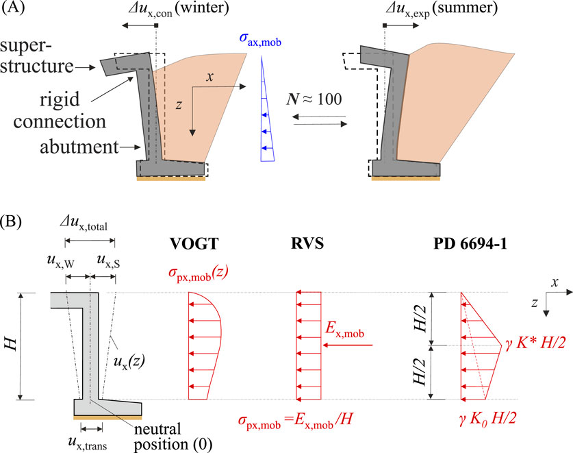
Figure 1. (A) Scheme of the soil-structure interaction of an integral bridge and its backfill, (B) Profile of analytical design approaches by Vogt (1984), RVS 15.02.12 (2019) and PD6694-1 (2020) for the lateral earth pressure on integral abutments in summer.
For traditional coarse-grained backfills, various earth pressure models exist, see, e.g., (RE-ING, 2023; RVS 15.02.12, 2019; PD6694-1, 2020; Kerokoski, 2006; Mass. DOT, 2024). These design approaches vary considerably and are often proposed based on experiments (Vogt, 1984; Springman et al., 1996; England et al., 2000; Tapper and Lehane, 2005) that have limitations, such as boundary effects or simplified abutment deformation (e.g., rigid “foot-point” rotation). Furthermore, they are predominantly derived using poorly-graded (fine) sands. In general, research on the SSI, both with experimental and/or numerical strategies, has focused on integral road bridges and poorly-graded materials, see Section 2. However, no studies are available that consider railway specifics, such as additional track (and traffic) loads, or railway-specific backfill designs. For example, according to DB guideline Ril 836 (2023), only well-graded sand-gravel mixtures are approved as backfill materials. As shown, e.g., in Stastny et al. (2024a) well-graded coarse-grained backfill material mobilizes significantly higher lateral stresses compared to uniformly-graded (fine) sands. Due to these shortcomings (and assumptions), further research is necessary and existing earth pressure approaches need to be carefully checked and improved if required.
Therefore, this study aims to quantify the various influences on the cyclic SSI behavior of integral railway bridges and compares the results to different analytical design approaches for the passive lateral stress mobilization from Germany, Austria and the United Kingdom (RE-ING, 2023; RVS 15.02.12, 2019; PD6694-1, 2020). It focuses on typical integral railway bridges in Germany with full height abutments on spread footings, either with or without additional support of concrete bored piles. Cyclic 2D and 3D finite element (FE) studies are conducted using practice-oriented bridge lengths of
The following research questions will be addressed in the in this work:
• What are the main drivers of the cyclic SSI?
• Which lateral stress profile is adequate for well-graded granular backfills, especially for longer integral railway bridges?
• What settlement accumulation in the backfill can be expected due to the horizontal SSI?
Based on the findings, recommendations are formulated for future structural design of integral (railway) bridges.
2 Review on the SSI of integral bridges
Integral abutments are subjected to cyclic variations in earth pressure primarily due to seasonal thermal expansions and contractions of the bridge deck. During warmer months, earth pressure behind the abutment increases, while it decreases during colder periods. These cyclic deformations also cause repeated compaction of granular backfills, leading to settlement accumulation, a phenomenon commonly referred to as “ratcheting” (England et al., 2000; Lehane, 2011; Morley et al., 2024). Scaled experiments and centrifuge tests (see below) have demonstrated that cyclic loading induces a continuous increase in earth pressures and progressive settlement accumulation during a bridge’s life. These effects are more pronounced in longer structures, as the magnitude of thermal deck displacements grows with length. The cyclic increase of stresses and settlements is influenced by various geotechnical and structural factors such as: geometry (length, height, skew, orientation) as well as stiffness of the bridge and abutment, temperature loading (daily, seasonal), abutment movements (magnitude, shape), backfill (material, density, moisture), foundation type and underground stiffness, site-specific conditions (Banks and Bloodworth, 2018; Abdel-Fattah et al., 2018; Hassan et al., 2024). This large number of influencing factors makes it challenging to accurately account for the SSI in design codes and to capture it numerically. The following sections provide a brief review of research on experimental testing and numerical analysis related to the SSI of integral bridges. Field monitoring or special transition zone designs, e.g., transition slabs (Dreier et al., 2011) or the inclusion of compressible material behind the abutment (Sigdel et al., 2023) will not be covered.
2.1 Laboratory testing
Numerous researchers, e.g., (Vogt, 1984; Springman et al., 1996; England et al., 2000; Lehane, 2011; Tapper and Lehane, 2005; Havinga et al., 2017; Walter et al., 2018; Grabe et al., 2019; Liu et al., 2022b; Luo et al., 2023; Alqarawi et al., 2024; Morley et al., 2024), have carried out experimental 1
Vogt (1984) conducted 1
Franke (1989) derived an equation for the monotonic (active and) passive earth pressure mobilization based on mechanical models. No cyclic experiments were involved. Nevertheless, the equation, as part of ÖNorm B 4434 (1993), is now used in the Austrian guide for integral bridges RVS 15.02.12 (2019) to cover the cyclic passive earth pressure mobilization. Bartl (2004) conducted additional small-scale 1
Small-scale 1
Xu et al. (2007) and Bloodworth et al. (2012) used cyclic triaxial tests with radial strain-control, showing that (fine) sands exhibit greater lateral stress buildup under cyclic loads compared to stiff clays. Havinga et al. (2017), Walter et al. (2018) and Liu et al. (2022b) conducted mid-scale 1
2.2 Numerical analysis
Most numerical studies on the SSI of integral bridges use the finite element method with focus on the structural behavior, e.g., (Dicleli, 2005; Civjan et al., 2007; Ooi et al., 2010; Zordan et al., 2011; David et al., 2014; LaFave et al., 2016; Quinn and Civjan, 2017; Della Pietra et al., 2019). In these studies, the soil behavior is often simplified by means of linear-elastic perfect-plastic soil models or (nonlinear) soil springs. Several FE studies, e.g., (Kerokoski, 2006; Efretuei, 2013; Abdel-Fattah et al., 2018; Sandberg et al., 2020; Liu et al., 2023; Silva et al., 2023; Abdullah and El Naggar, 2023), used the elastoplastic Hardening Soil model (Schanz et al., 1999). Only a few researcher conducted studies on the SSI using finite-difference methods (Wood, 2004; Bloodworth et al., 2012; Banks and Bloodworth, 2018; Liu et al., 2022a) or discrete element methods (Zorzi et al., 2017; Xu and Guo, 2021).
Abdel-Fattah and Abdel-Fattah (2019) conducted 2D FE analyses (
Bloodworth et al. (2012) and Banks and Bloodworth (2018) conducted cyclic 2D FE simulations to examine earth pressure mobilization behind frame bridges on spread footings (
Stastny et al. (2024a) and Stastny et al. (2024b) performed cyclic SSI studies using 2D FE models with three advanced elastoplastic [DeltaSand by Galavi (2021), Sanisand-MS by Liu et al. (2019)] or hypoplastic [Hypo+IGS by Wolffersdorff (1996); Niemunis and Herle (1997)] soil models for cyclic loading. All models were calibrated based on laboratory tests for a well-graded gravel backfill material. Two soil models proved to be capable of capturing the main mechanisms of the cyclic SSI, at least for the considered 20 seasonal cycles. Further studies demonstrated that the cyclic mobilization of earth pressure (in the summer position) is highly influenced by the actual displacement pattern of the abutment. The analyses also exhibited significantly higher cyclic earth pressures for well-graded gravels compared to poorly-graded sands. The SSI behavior for all materials was primarily governed by the “overall” stiffness of the soil model, including the small-strain stiffness.
2.3 Dynamic vertical interaction
This research focuses on the horizontal cyclic SSI due to seasonal temperature deformation of the integral bridge deck. However, it has to be noted that this interaction mechanism is superposed by the vertical dynamic interaction of train, track and backfill. Transition zones of railway bridges with granular backfills are characterized by sharp changes of stiffness (from structure to backfill) as well as differential settlements (in the ballasted track) due to traffic loads. The appearance of settlements may start a deterioration loop, leading to amplified vertical dynamic track loads and accelerations, the development of “hanging sleepers” and further expansion of settlement troughs, compare, e.g., Wang and Markine (2019) and Paixão et al. (2016), Paixão et al. (2021). This, in turn, can accelerate track degradation and increase maintenance costs. Paixão et al. (2016) found that both the settlement amplitude and profile strongly influence this process. The horizontal SSI of longer integral bridges adds additional settlement accumulation to the system, which may intensify and speed up the degradation described above. The acceptability of backfill settlements due to the horizontal cyclic SSI of integral bridges therefore cannot be judged independently of the vertical dynamic train-track interaction. The DB guideline for integral railway bridges Ril 804.4501 (2021) in Germany requires the use of a special transition zone design, such as approach slabs, when horizontal seasonal deck deformations exceed 20 mm. This corresponds to a concrete deck length of approximately 50 m. The requirement is primarily based on experience and repeated evaluation of track measurement data from existing integral railway bridges with or without approach slabs. However, until today, no research has focused on the combined effects of the horizontal cyclic and the vertical dynamic interaction in the transition zones of long integral railway bridges. Although it is not the focus of this study, it remains a significant question for future research.
3 Objects of study
3.1 Bridge geometries and variations
In this investigation, reference structural models of integral railway bridges are used to study the cyclic soil-structure interaction. The geometries are taken from real life projects and are adjusted for easier parametrization. Typically, in Germany integral railway bridges are constructed with full height abutments on a spread footing, either with or without additional support of concrete bored piles. Other forms of embedded wall abutments or bank pad abutments on piles (PD6694-1, 2020) are less common. The same can be said for any form of steel pile profiles, which are popular, e.g., in the United States (Liu et al., 2022c), but rarely used in Germany.
The reference models consist of concrete deck superstructures (
The influence of the following variations on the cyclic SSI of integral bridges is investigated:
• Bridge lengths
• Abutment heights
• Abutment stiffnesses
• Backfill stiffnesses
• Foundation and underground stiffnesses
3.2 Backfill materials
According to the DB guideline Ril 836 (2023), railway bridge backfills must use well-graded sands or gravels, containing no more than 5% fine particles smaller than 0.063 mm. These materials are compacted in situ to 100% Proctor density in 30 cm layers. To ensure appropriate grading and compaction, the material must have a uniformity coefficient
The gravel analyzed in this study is a representative, well-graded material suitable for bridge backfills. Its grain size distribution includes a mean grain size of
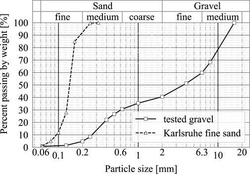
Figure 2. Grain size distribution of the tested well-graded gravel (Stastny et al., 2024a) and of Karlsruhe fine sand (Wichtmann and Triantafyllidis, 2016).
In addition to gravel, the well-known Karlsruhe fine sand (Wichtmann and Triantafyllidis, 2016) is considered in this investigation for comparison reasons. Due to its poor grading, this sand is typically not applicable for backfills of bridges, see Stastny et al. (2024a). However, many experimental as well as numerical studies on cyclic SSI behavior of integral bridges have been focused on poorly-graded (fine) sand, see Section 2. The Karlsruhe fine sand in Wichtmann and Triantafyllidis (2016) has a subangular shape with a mean grain size
4 Analytical methods for the mobilized earth pressure
In this contribution, analytical design approaches from Germany, Austria and Great Britain (Vogt, 1984; RVS 15.02.12, 2019; PD6694-1, 2020) are compared against the numerical simulations. In the following, the different approaches will be briefly summarized:
In Germany, for both integral road (RE-ING, 2023) and railway (Ril 804.4501, 2021) bridges the mobilization of passive earth pressure on the abutment (in its summer position) is determined according to Vogt (1984). Based on large-scale 1
For the discussed studies, the passive earth pressure coefficient
In Austria, the guideline for the design of integral bridges RVS 15.02.12 (2019) provides a deformation-dependent earth pressure approach based on ÖNorm B 4434 (1993) and Franke (1989). Here, the earth pressure resultant
Equation 2 contains the soil stress resultants
In the United Kingdom, PD6694-1 (2020) regulates the design of integral bridges. A summary on the development of PD 6694–1 and its previous versions can be found, e.g., in Morley et al. (2024). The United Kingdom approach (Equation 3) is also used in a similar manner by other countries, such as Switzerland (ASTRA 12004, 2011) and Ireland (Place et al., 2006). Up to a maximum thermal deformation criteria of 40 mm, the earth pressure on integral abutments is mainly assessed using the limit equilibrium method. Based on this, for full height frame abutments on spread footings, PD 6694–1 proposes a bilinear profile for the cyclic lateral earth pressure that develops during the design life. It is defined by a peak value of
Here again
5 2D and 3D finite element analyses
5.1 Constitutive model for cyclic loading
In this investigation, an elastoplastic, state-dependent material model for sand called DeltaSand is employed to simulate the cyclic loading behavior. It was developed by Galavi (2021) and has demonstrated to capture the essential characteristics of small strain and cyclic loading behavior both on element test level and in boundary value problems (Fetrati et al., 2024; Galavi and Martinelli, 2024; Stastny et al., 2024b). The model defines the behavior of sand using a single set of 16 parameters that represent the soil’s intrinsic properties. The current void ratio (i.e., the relative density) and effective stress serve as the primary state variables, influencing key soil characteristics such as stiffness, strength, dilation, and compressibility. The model incorporates distinct yield surfaces for deviatoric, volumetric, and tensile stresses within the effective principal stress space. The deviatoric yield surface, shaped like a cone, includes one isotropic and two kinematic hardening surfaces. The isotropic surface governs monotonic loading, while the kinematic surfaces handle cyclic shear behavior. Elastic behavior is modeled within the kinematic surfaces, taking into account small strain stiffness. To accurately represent soil stiffness during cyclic loading, the extended Masing rule (Vucetic, 1990) is applied. The volumetric yield surface, or “cap,” expands isotropically but does not account for cyclic behavior during volumetric compression. Depending on the stress state, the model activates one of these surfaces, allowing it to predict soil response under different loading conditions. In this study, the Mohr-Coulomb yield surface was selected to define the cone-shaped failure criteria.
The material model has been thoroughly calibrated for the tested gravel material (see Section 3.2) in Stastny et al. (2024a). In Stastny et al. (2024b), DeltaSand has also been compared to other advanced soil models, both on element test level and in a 2D FE design case study of an integral bridge. DeltaSand successfully captured the key mechanisms of cyclic soil-structure interaction, including the cyclic increase of earth pressure on the abutment during summer and the progressive accumulation of settlements in the backfill, particularly over the first 10 seasonal cycles. Additionally, DeltaSand predicted the highest earth pressures, thus making it the most conservative material model choice for the parametric study in the present investigation. Further details on the soil model and its calibration for Karlsruhe fine sand and the tested gravel material can be found in Galavi (2021) and Stastny et al. (2024a).
5.2 Numerical model description
In the following, the 2D and 3D FE models for the cyclic soil-structure interaction analysis of integral railway bridges are described. They represent the bridge geometries and the variations of the abutment, backfill and foundation stiffnesses summarized in Section 3. The aim is to quantify the various influences on the cyclic SSI behavior of typical integral bridges and compare the results to different analytical design approaches for the passive lateral stress mobilization. The FE modelling approach (in combination with the DeltaSand material set) was validated based on extensive preliminary studies including mesh sensitivity and boundary studies, interface examinations [e.g., in Stastny and Tschuchnigg (2023)], back analysis of 1
Bridges on spread footing were simulated by means of plane strain FE models in Plaxis 2D version V23.2 (Bentley Systems, 2023) with total dimensions of at least 300 m (length) and 60 m (height) to minimize the effects of boundary conditions. Due to the symmetrical built of the reference bridges, only half of the bridge and its surrounding soil had to be computed, see Figure 3A. The FE mesh was discretized using 15-noded elements (
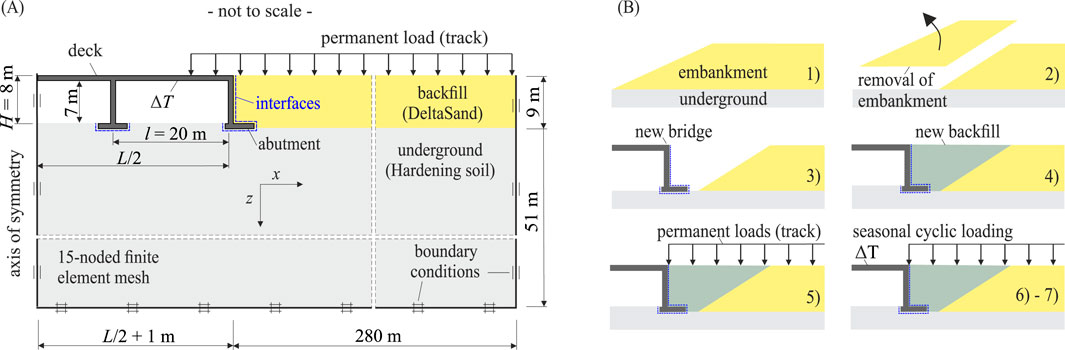
Figure 3. (A) 2D FE model with focus on the SSI of an integral bridge, (B) Calculation phases.
Figure 3B illustrates the progression of the simulation phases. In the initial stage, an existing embankment was considered. The initial stress state was established through a gravity loading procedure, which calculates vertical stresses by applying gravitational loads
The SSI calculations of integral bridges with deep foundation were conducted in Plaxis 3D (version V23.2). To take advantage of the bridge’s symmetry, only half of the structure and the adjacent soil were modeled, see Figure 4. The mesh was generated using quadratic tetrahedral elements (shape function of
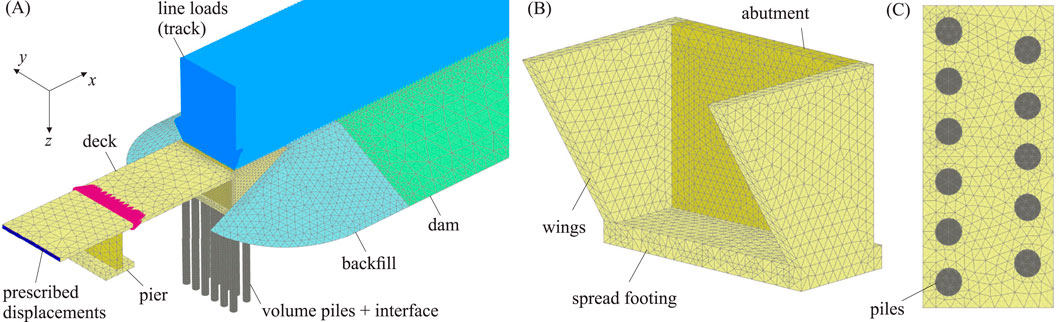
Figure 4. (A) 3D FE model, (B) View of box abutment on spread footing, (C) Top view of foundation with pile layout (two rows).

Table 1. Free horizontal temperature deformation
5.3 Temperature loading
As explained in Section 2 the main driver of the cyclic SSI is the seasonal temperature deformation of the integral bridge deck. The corresponding temperature profile was taken from DIN EN 1991-1-5/NA (2010) for concrete bridges. Therefore, a characteristic constant temperature change with a return period of 50 years with
5.4 Numerical model with analytical loading
The differences of the analytical approaches from Section 4 will be compared to the SSI results not only in terms of lateral stresses but also with regard to the abutment’s bending moments. The FE models from Section 5.2 were further used for this purpose. The calculation phases 1 to 5 were computed as described before. In phase 6, the summer temperature change of the bridge deck was simulated also specified above. However, the backfill was deactivated from the top edge of the spread footing up to the ground surface and replaced by a similar vertical line load on the remaining backfill and footing. The line load was calculated by
6 Results and discussion
In this section, the results of the numerical SSI parameter studies are discussed and compared against the analytical design approaches from Section 4. The main focus will be on the following quantities:
• lateral stresses
• bending moments
• cyclic settlements
• horizontal deformations
6.1 Influence of bridge length and abutment height
Figure 5 presents the lateral stress distributions in phase summer S2 and S10 of bridges with length
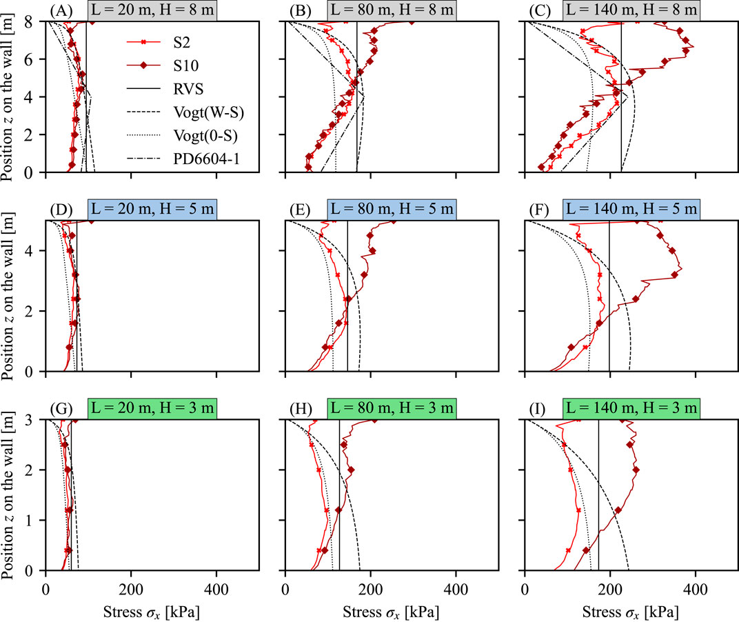
Figure 5. Lateral stress distribution
Figures 6A–C illustrates the development of the total lateral earth pressure forces
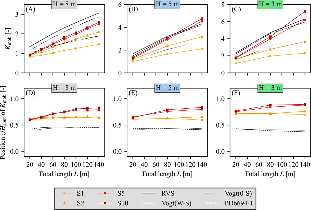
Figure 6. (A–C) Normalized lateral forces
In Figure 7 the abutment’s bending moments from cyclic loading (i.e., without bending moments from the initial phases) in summer 2 are displayed for
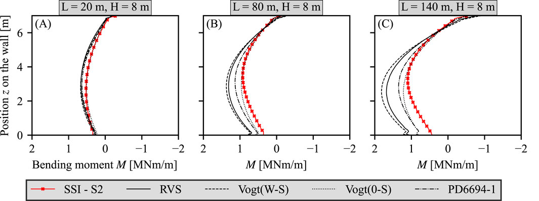
Figure 7. Bending moments of the abutment from cyclic loading in calculation phases summer S2 and winter W2 compared against the results from the analytical methods: (A) Height
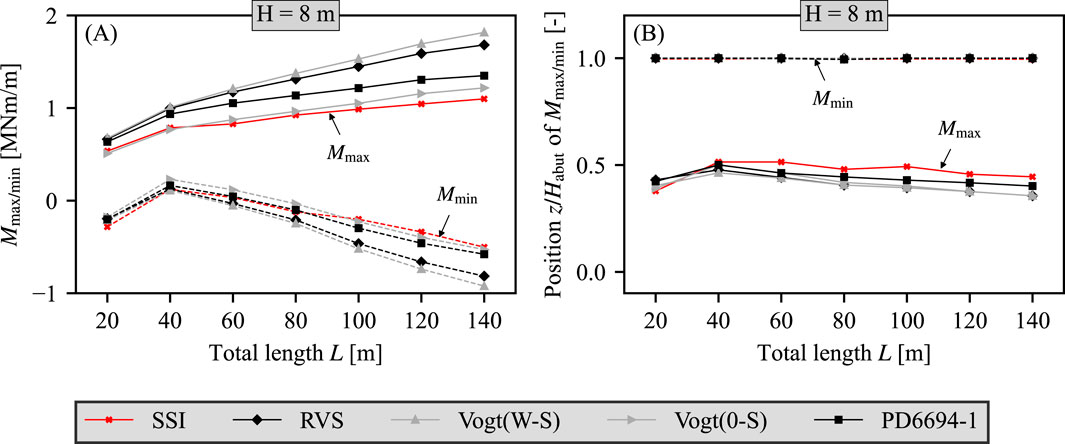
Figure 8. (A) Minimum and maximum bending moment
One big advantage of the 2D FE model with direct temperature loading on the bridge deck is its ability to simulate the reaction of both structure and soil during the successive thermal loading steps in each calculation phase. This allows to determine how strongly the abutment’s temperature deformation is restricted by the backfill. For this reason, the ratio of the horizontal top deformation
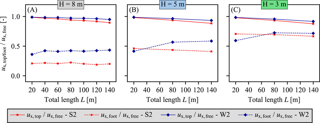
Figure 9. Normalized horizontal displacements of the abutment top
Finally, the development of settlements
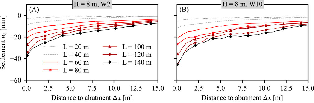
Figure 10. Settlement accumulation for abutment heights
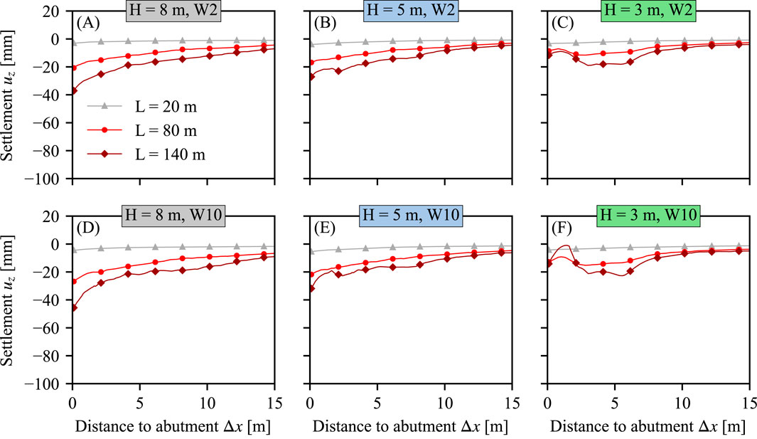
Figure 11. Settlement accumulation for abutment heights
However, as summarized in Section 2.3, the acceptability of backfill settlements due to the horizontal cyclic SSI of integral bridges cannot be judged independently of the vertical dynamic train-track interaction. Research by Paixão et al. (2016) and Wang and Markine (2019) suggests that for such settlements profiles much higher dynamic vertical track loads and accelerations are likely to occur and will be accompanied by hanging sleepers, i.e., sleepers that lose the direct contact with the ballast in its unloaded position. These effects are clear indicators for a rapid deterioration of the ballast track condition in the transition zone, which leads to a bad track alignment and increased maintenance. Clearly, more research is needed on the combined effects of the horizontal cyclic and the vertical dynamic interaction in the transition zones of longer integral railway bridges. The results of the present study may be a good starting point, as they allow quantifying the isolated effect of the horizontal SSI on the settlement accumulation of integral bridges depending on their deck length. In the absence of further research, the authors recommend implementing specialized transition zone designs, i.e., approach slabs, for seasonal deck deformations beyond 20 mm based on the specifications in DB guideline Ril 804.4501 (2021), compare Section 2.3.
6.2 Influence of abutment and backfill stiffness
The influence of the abutment stiffness has been studied in additional calculations with a 2 m thick uncracked and a 1 m thick cracked abutment. To approximately account for the cracking, the abutment stiffness was reduced to 60% in accordance with DIN EN 1992-2 (2010). The
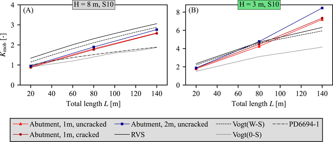
Figure 12. (A–B) Normalized lateral forces
To evaluate the influence of backfill material on the cyclic SSI two different backfill materials, the well-graded gravel and the poorly-graded Karlsruhe fine sand from Section 3.2, are studied with varying initial relative densities
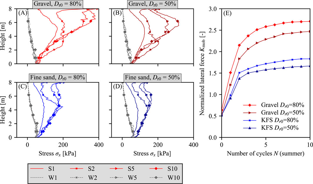
Figure 13. (A–D) Cyclic lateral stress distribution
The described trends also occur for different bridge lengths
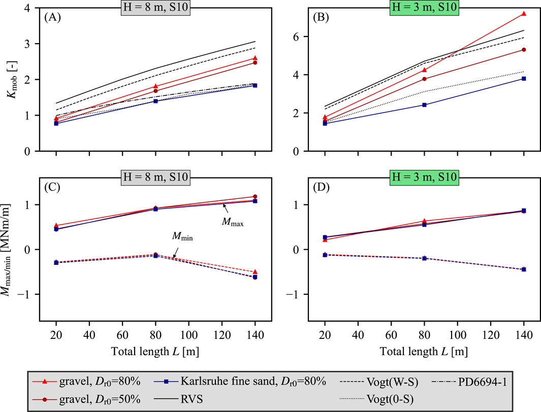
Figure 14. (A–B) Normalized lateral forces
In summary, the use of poorly-graded fine sands in numerical or experimental studies on the cyclic SSI of integral bridges could lead to an underestimation of the cyclic lateral earth pressures. Future numerical and experimental studies on the cyclic SSI should include representative, well-graded backfill materials.
6.3 Influence of foundation and underground stiffness
At last, the influence of the foundation type and underground stiffness was investigated using 3D FE models described in Section 5.2. The lateral stresses were evaluated in the interface at the middle of the abutment (in the axis of symmetry). The resulting
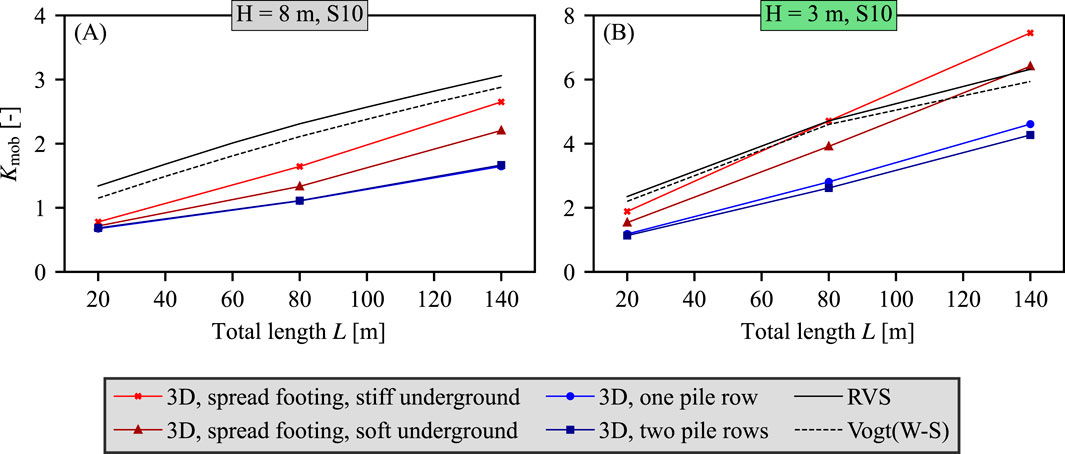
Figure 15. Normalized lateral forces
7 Conclusion
In this contribution, a comprehensive numerical investigation on the cyclic SSI behavior of integral railway bridges was conducted. A series of parametric studies were performed, examining the effects of varying bridge geometries (lengths
The key findings of this research are.
• The cyclic SSI, specifically the passive mobilization of earth pressure, is strongly determined by the bridge length, abutment height, as well as the backfill and foundation/underground stiffness. The abutment stiffness only has a minor influence in this study.
• With increasing deck length
• For tall abutments of
• The backfill material strongly influences the cyclic earth pressure mobilization. Higher stresses are mobilized with the well-graded gravel compared to the poorly-graded fine sand. The increase of the relative density also leads to (slightly) higher earth pressures.
• The stiff gravel material experiences peak stresses and cyclic stress increases predominantly in the upper half of the abutment. This is particularly noticeable for long bridges with short(er) abutments. The stress profiles of the analytical design approaches do not match this distribution, predicting peak stresses at mid-height or below. The FEA with fine sand showed peak stresses in the middle of the abutment.
• Despite the higher earth pressures, gravel materials cause no greater bending moments in the abutment compared to fine sand. This is due to the higher position
• The study results indicate that current design approaches may not always be conservative, especially since only 10 seasonal cycles have been simulated. Particularly, for long bridges with shorter abutments, deficits in the current design approaches have been found. Similar to the recommendation in PD6694-1 (2020), numerical SSI analysis should be considered for longer integral bridges with significant translation movement of the abutment, e.g., bridges with short heights.
• For the future use of the approach by Vogt (1984), the full thermal movement range of the bridge deck from the winter to the summer position (W–S) should be considered to allow a safe design.
• The simplified rectangular stress profile of RVS 15.02.12 (2019) approximates the effects of Vogt’s parabolic approach (W–S) well and could constitute an easy-to-use method for the structural design of bridges.
• The approach of PD6694-1 (2020) is (only) appropriate for bridge length up to 40 m (based on the evaluation of
• Backfill settlements increase with the number of cycles and bridge length. More research is needed to evaluate its influence on the vertical dynamic train-track interaction. Consequently, at this stage, for deck deformations beyond 20 mm, the implementation of approach slabs in accordance with Ril 804.4501 (2021) is recommended.
Future research will focus on the SSI behavior of integral bridges with different typical transition zone designs, such as wedge-shaped cemented granular mixtures or transition slabs. Additionally, more research should be conducted with regard to material models and its calibration for the cyclic SSI, which would allow to simulate all seasonal and potentially even daily cycles during a bridge’s lifetime. Experimental large scale 1
Data availability statement
The original contributions presented in the study are included in the article/supplementary material, further inquiries can be directed to the corresponding author.
Author contributions
AS: Conceptualization, Data curation, Formal Analysis, Investigation, Methodology, Software, Supervision, Validation, Visualization, Writing–original draft, Writing–review and editing. AE: Formal Analysis, Visualization, Writing–review and editing. VG: Resources, Software, Writing–review and editing. FT: Supervision, Writing–review and editing.
Funding
The author(s) declare that financial support was received for the research, authorship, and/or publication of this article. The first author is employed by DB InfraGO AG. The second author received support from DB InfraGO AG for his master’s thesis. The funder was not involved in the study design, collection, analysis, interpretation of data, the writing of this article, or the decision to submit it for publication.
Acknowledgments
We gratefully acknowledge the financial support from the TU Graz Open Access Publishing Fund for providing the open access funding.
Conflict of interest
Author AS was employed by DB InfraGO AG. Author VG was employed by Witteveen+Bos.
The remaining authors declare that the research was conducted in the absence of any commercial or financial relationships that could be construed as a potential conflict of interest.
Generative AI statement
The author(s) declare that no Generative AI was used in the creation of this manuscript.
Publisher’s note
All claims expressed in this article are solely those of the authors and do not necessarily represent those of their affiliated organizations, or those of the publisher, the editors and the reviewers. Any product that may be evaluated in this article, or claim that may be made by its manufacturer, is not guaranteed or endorsed by the publisher.
References
Abdel-Fattah, M., and Abdel-Fattah, T. (2019). Behavior of integral frame abutment bridges due to cyclic thermal loading: nonlinear finite-element analysis. J. Bridge Eng. 24, 04019031. doi:10.1061/(ASCE)BE.1943-5592.0001394
Abdel-Fattah, M., Abdel-Fattah, T., and Hemada, A. (2018). Nonlinear finite-element analysis of integral abutment bridges due to cyclic thermal changes. J. Bridge Eng. 23, 04017134. doi:10.1061/(ASCE)BE.1943-5592.0001183
Abdullah, A., and El Naggar, H. (2023). Soil-structure interaction of integral abutments. Transp. Geotech. 38, 100900. doi:10.1016/j.trgeo.2022.100900
Alqarawi, A., Leo, C., Liyanapathirana, D., and Hu, P. (2024). Soil-structure interaction issues in integral abutment bridges. Transp. Geotech. 48, 101296. doi:10.1016/j.trgeo.2024.101296
ASTRA 12004 (2011). Guideline on structural details of bridges: chapter 3: bridge ends (in German). Bern, Switzerland: ASTRA.
Banks, J., and Bloodworth, A. (2018). Lateral stress profiles on integral bridge abutments. Proc. Institution Civ. Eng. - Bridge Eng. 171, 155–168. doi:10.1680/jbren.17.00017
Bartl, U. (2004). On the mobilization of passive earth pressure in cohesionless soil (in German). Dissertation. Dresden, Germany: Technische Universität Dresden.
Bloodworth, A., Xu, M., Banks, J., and Clayton, C. (2012). Predicting the earth pressure on integral bridge abutments. J. Bridge Eng. 17, 371–381. doi:10.1061/(asce)be.1943-5592.0000263
Burke, J., and Martin, P. (2009). Integral and semi-integral bridges. Oxford, UK: John Wiley and Sons.
Civjan, S., Bonczar, C., Brena, S., DeJong, J., and Crovo, D. (2007). Integral abutment bridge behavior: parametric analysis of a Massachusetts bridge. J. Bridge Eng. 12, 64–71. doi:10.1061/(ASCE)1084-0702(2007)12:1(64)
Clayton, C., Xu, M., and Bloodworth, A. (2006). A laboratory study of the development of earth pressure behind integral bridge abutments. Géotechnique 56, 561–571. doi:10.1680/geot.2006.56.8.561
Cosgrove, E., and Lehane, B. (2003). Cyclic loading of loose backfill placed adjacent to integral bridge abutments. Int. J. Phys. Model. Geotechnics 3, 09–16. doi:10.1680/ijpmg.2003.030302
David, T., Forth, J., and Ye, J. (2014). Superstructure behavior of a stub-type integral abutment bridge. J. Bridge Eng. 19, 04014012. doi:10.1061/(ASCE)BE.1943-5592.0000583
Della Pietra, R., Oberwalder, S., and Tue, N. V. (2019). Key aspects in the design of integral bridges (in German). Beton- und Stahlbetonbau 114, 683–691. doi:10.1002/best.201900030
Denton, S., Riches, O., Christie, T., and Kidd, A. (2011). “Developments in integral bridge design,” in Bridge design to eurocodes: UK implementation. Editor S. Denton (London, UK: ICE Publishing), 463–480.
Dicleli, M. (2005). Integral abutment-backfill behavior on sand soil-pushover analysis approach. J. Bridge Eng. 10, 354–364. doi:10.1061/(ASCE)1084-0702(2005)10:3(354)
DIN EN 1991-1-5/NA (2010). Germany National Annex to Eurocode 1: actions on structures – Part 1–5: general actions – thermal actions. Berlin, Germany: DIN.
DIN EN 1992-2 (2010). Eurocode 2: design of concrete structures - Part 2: concrete bridges. Berlin, Germany: DIN.
Dreier, D., Burdet, O., and Muttoni, A. (2011). Transition slabs of integral abutment bridges. Struct. Eng. Int. 21, 144–150. doi:10.2749/101686611X12994961034174
Efretuei, E. (2013). Thermal impact on soil-structure interaction for integral bridges. PhD thesis, Leeds, United Kingdom. University of Leeds.
England, G., Tsang, N., and Bush, D. (2000). Integral bridges: a fundamental approach to the time-temperature loading problem. London, UK: Telford.
Fetrati, M., Galavi, V., Goodarzi, M., Mörz, T., and Kreiter, S. (2024). Simulation of cone penetrometer tests in sand using three advanced constitutive models: a comparative study. Comput. Geotechnics 176, 106683. doi:10.1016/j.compgeo.2024.106683
Franke, D. (1989). Calculation of retaining walls using various mechanical models (in German). Dresden, Germany: Ohde Kolloquium.
Galavi, V. (2021). DeltaSand: a state dependent double hardening elasto-plastic model for sand: formulation and validation. Comput. Geotechnics 129, 103844. doi:10.1016/j.compgeo.2020.103844
Galavi, V., and Martinelli, M. (2024). MPM simulation of the installation of an impact-driven pile in dry sand and subsequent axial bearing capacity. J. Geotechnical Geoenvironmental Eng. 150, 04024019. doi:10.1061/JGGEFK.GTENG-11592
Grabe, J., Vogel, P., and Rombach, G. (2019). “Investigation of the soil structure interaction of integral bridges,” in Advances in engineering materials, structures and systems: innovations, mechanics and applications. Editor A. Zingoni (Cape Town, South Africa: ImprintCRC Press), 1–5. doi:10.1201/9780429426506
Granitzer, A., Felic, H., Leo, J., Stastny, A., and Tschuchnigg, F. (2024). Numerical investigation of pile foundation systems employing an enhanced embedded finite element. Front. Built Environ. 10, 1454266 doi:10.3389/fbuil.2024.1454266
Hassan, M., Liyanapathirana, D., Fuentes, W., Leo, C., and Hu, P. (2024). A review of soil deformation and lateral pressure ratcheting phenomena in integral abutment bridges. Transp. Geotech. 49, 101388. doi:10.1016/j.trgeo.2024.101388
Havinga, M., Tschuchnigg, F., Marte, R., and Schweiger, H. (2017). Small scale experiments and numerical analysis of integral bridge abutments. Proc. ICSMGE 2017, 753–756.
Kerokoski, O. (2006). Soil-structure interaction of long jointless bridges with integral abutments. Phd thesis Tampere, Finland: Tampere University of Technology.
LaFave, J., Riddle, J., Jarrett, M., Wright, B., Svatora, J., An, H., et al. (2016). Numerical simulations of steel integral abutment bridges under thermal loading. J. Bridge Eng. 21, 04016061. doi:10.1061/(ASCE)BE.1943-5592.0000919
Lehane, B. (2011). Lateral soil stiffness adjacent to deep integral bridge abutments. Géotechnique 61, 593–603. doi:10.1680/geot.9.P.135
Liu, H., Abell, J., Diambra, A., and Pisanò, F. (2019). Modelling the cyclic ratcheting of sands through memory-enhanced bounding surface plasticity. Géotechnique 69, 783–800. doi:10.1680/jgeot.17.P.307
Liu, H., Han, J., and Parsons, R. (2022a). Effects of seasonal temperature change-induced abutment movements on backfill surface settlements behind integral bridge abutments–numerical analysis. Comput. Geotechnics 149, 104884. doi:10.1016/j.compgeo.2022.104884
Liu, H., Han, J., and Parsons, R. (2022b). Settlement and horizontal earth pressure behind model integral bridge abutment induced by simulated seasonal temperature change. J. Geotechnical Geoenvironmental Eng. 148, 04022043. doi:10.1061/(ASCE)GT.1943-5606.0002812
Liu, H., Han, J., and Parsons, R. (2023). Numerical analysis of geosynthetics to mitigate seasonal temperature change-induced problems for integral bridge abutment. Acta Geotech. 18, 673–693. doi:10.1007/s11440-022-01614-5
Liu, H., Han, J., and Parsons, R. L. (2022c). Integral bridge abutments in response to seasonal temperature changes: state of knowledge and recent advances. Front. Built Environ. 8. doi:10.3389/fbuil.2022.916782
Luo, S., Huang, Z., Asia, Y., De Luca, F., De Risi, R., Harkness, J., et al. (2023). Physical and numerical investigation of integral bridge abutment stiffness due to seasonal thermal loading. Transp. Geotech. 42, 101064. doi:10.1016/j.trgeo.2023.101064
Marx, S., and Seidl, G. (2011). Integral railway bridges in Germany. Struct. Eng. Int. 21, 332–340. doi:10.2749/101686611X12994961034534
Mass. DOT (2024). Bridge manual. Boston, MA, United States. Highway Division, Massachusetts Department of Transportation.
Morley, D., Madabhushi, G., Sakufiwa, D., and Thusyanthan, I. (2024). Investigation into soil ratcheting behind integral bridges using centrifuge modelling. Proc. Institution Civ. Eng. - Bridge Eng., 1–17. doi:10.1680/jbren.23.00046
Niemunis, A., and Herle, I. (1997). Hypoplastic model for cohesionless soils with elastic strain range. Mech. Cohesive-frictional Mater. 2, 279–299. doi:10.1002/(SICI)1099-1484(199710)2:4<279::AID-CFM29>3.0.CO;2-8
ÖNorm B 4434 (1993). Earth pressure calculations (in German). Vienna, Austria: Österreichisches Normungsinstitut.
Ooi, P., Lin, X., and Hamada, H. (2010). Numerical study of an integral abutment bridge supported on drilled shafts. J. Bridge Eng. 15, 19–31. doi:10.1061/(ASCE)BE.1943-5592.0000037
Paixão, A., Fortunato, E., and Calçada, R. (2016). A numerical study on the influence of backfill settlements in the train/track interaction at transition zones to railway bridges. Proc. Institution Mech. Eng. Part F J. Rail Rapid Transit 230, 866–878. doi:10.1177/0954409715573289
Paixão, A., Varandas, J., and Fortunato, E. (2021). Dynamic behavior in transition zones and long-term railway track performance. Front. Built Environ. 7, 658909. doi:10.3389/fbuil.2021.658909
PD6694-1 (2020). Recommendations for the design of structures subject to traffic loading to BS EN 1997-1:2004. London, UK: BSI.
Place, D., Farooq, I., and Tang, V. (2006). “Integral bridges with frame abutments,” in Proceedings of the 1st international Conference on Advances in bridge engineering (London, UK), 26–28.
Quinn, B., and Civjan, S. (2017). Parametric study on effects of pile orientation in integral abutment bridges. J. Bridge Eng. 22, 04016132. doi:10.1061/(ASCE)BE.1943-5592.0000952
RE-ING (2023). Guideline for the design, structural configuration, and equipment of civil engineering structures (in German). Bergisch Gladbach, Germany: BAST.
Ril 804.4501 (2021). Standard for planning, construction, and maintenance of railway bridges and other civil engineering structures. Integral and semi-integral bridges (in German). Frankfurt am Main, Germany: DB Netz AG.
Ril 836 (2023). Standard for planning, construction, and maintenance of earthworks and other geotechnical structures (in German). Frankfurt am Main, Germany: DB Netz AG.
RVS 15.02.12 (2019). Design and construction of integral bridges (in German). Vienna, Austria: Österreichische Forschungsgesellschaft Strasse-Schiene-Verkehr FSV.
Sandberg, J., Magnino, L., Nowak, P., Wiechecki, M., and Thusyanthan, I. (2020). The integral bridge design concept for the third runway at heathrow, UK. Proc. Institution Civ. Eng. - Bridge Eng. 173, 112–120. doi:10.1680/jbren.19.00044
Schanz, T., Vermeer, P., and Bonnier, P. (1999). “The hardening soil model: formulation and verification,” in Beyond 2000 in computational geotechnics (London, United Kingdom: Routledge), 281–296.
Sigdel, L., Lu, M., Al-qarawi, A., Leo, C., Liyanapathirana, S., and Hu, P. (2023). Application of engineered compressible inclusions to mitigating soil-structure interaction issues in integral bridge abutments. J. Rock Mech. Geotechnical Eng. 15, 2132–2146. doi:10.1016/j.jrmge.2022.12.033
Silva, P., Costa, Y., Walter, J., Kouchaki, B., Zornberg, J., and Costa, C. (2023). Numerical evaluation of a semi-integral bridge abutment under cyclic thermal movements. Transp. Geotech. 39, 100938. doi:10.1016/j.trgeo.2023.100938
Springman, S., Norish, A., and Ng, C. (1996). TRL Report 146: cyclic loading of sand behind integral bridge abutments. Berkshire, UK: Highways Agency - Transport Research Laboratory.
Stastny, A., Knittel, L., Meier, T., and Tschuchnigg, F. (2024a). Experimental determination of hypoplastic parameters and cyclic numerical analysis for railway bridge backfills. Acta Geotech. 19, 6899–6916. doi:10.1007/s11440-024-02312-0
Stastny, A., Medicus, G., Galavi, V., Tafili, M., and Tschuchnigg, F. (2024b). Evaluation of advanced soil models for the cyclic soil-structure interaction of integral bridges. Acta Geotechn. (accepted).
Stastny, A., Stein, R., and Tschuchnigg, F. (2022). “Long-term monitoring of the transition zone of an integral railway bridge in Germany,” in Proc. 11th international symposium on field monitoring in geomechanics (United Kingdom: Imperial College London), 1–7.
Stastny, A., and Tschuchnigg, F. (2022). “Numerical studies on soil structure interaction of integral railway bridges with different backfills,” in Proc. 16th IACMAG conference (Torino, Italy), 338–345.
Stastny, A., and Tschuchnigg, F. (2023). “Numerical studies on the use of zero thickness interfaces in cyclic soil structure interaction analysis,” in Proc. 10th NUMGE conference (Imperial College London, United Kingdom), 1–6.
Szczyrba, S. (2013). Settlement-minimizing construction of the backfill area of bridge abutments (in German). Dissertation. Freiberg, Germany: Technische Universität Bergakademie Freiberg.
Tapper, L., and Lehane, B. (2005). “Lateral stress development on integral bridge abutments,” in Developments in mechanics and structures of material. Editors A. Deeks, and H. Hao (CRC Press), 2, 1069–1075.
Tue, N. V., Della Pietra, R., and Mayer, M. (2021). “Integral bridges – structural behavior and suggestions for design, including existing bridges (in German),” in Beton-kalender 2021. Editors K. Bergmeister, F. Fingerloos, and J.-D. Wörner (Berlin: Ernst and Sohn).
Vogt, N. (1984). Determination of earth resistance during monotonic and cyclic wall movements in sand. (in German). Dissertation. Stuttgart, Germany: Universität Stuttgart.
Vucetic, M. (1990). Normalized behavior of clay under irregular cyclic loading. Can. Geotechnical J. 27, 29–46. doi:10.1139/t90-004
Walter, J., Morsy, A., and Zornberg, J. (2018). “Experimental and numerical investigation of lateral earth pressures generated from repeated loading,” in IFCEE 2018 (American society of civil engineers), 158–168. doi:10.1061/9780784481608.016
Wang, H., and Markine, V. (2019). Dynamic behaviour of the track in transitions zones considering the differential settlement. J. Sound Vib. 459, 114863. doi:10.1016/j.jsv.2019.114863
Wenner, M., Seidl, G., Garn, R., and Marx, S. (2019). Long-term behavior of a 170-meter-long integral railway bridge (in German). Bautechnik 96, 120–132. doi:10.1002/bate.201800068
Wichtmann, T., and Triantafyllidis, T. (2016). An experimental database for the development, calibration and verification of constitutive models for sand with focus to cyclic loading: part i—tests with monotonic loading and stress cycles. Acta Geotech. 11, 739–761. doi:10.1007/s11440-015-0402-z
Wolffersdorff, P.-A. v. (1996). A hypoplastic relation for granular materials with a predefined limit state surface. Mech. Cohesive–frictional Mater. 1, 251–271. doi:10.1002/(SICI)1099-1484(199607)1:3<251::AID-CFM13>3.0.CO;2-3
Xu, M. (2005). The behaviour of soil behind full-height integral abutments. PhD thesis. Southampton, United Kingdom: University of Southampton.
Xu, M., Bloodworth, A., and Clayton, C. (2007). Behavior of a stiff clay behind embedded integral abutments. J. geotechnical geoenvironmental Eng. 133, 721–730. doi:10.1061/(ASCE)1090-0241(2007)133:6(721)
Xu, M., and Guo, J. (2021). DEM study on the development of the earth pressure of granular materials subjected to lateral cyclic loading. Comput. Geotechnics 130, 103915. doi:10.1016/j.compgeo.2020.103915
Zordan, T., Briseghella, B., and Lan, C. (2011). Parametric and pushover analyses on integral abutment bridge. Eng. Struct. 33, 502–515. doi:10.1016/j.engstruct.2010.11.009
Keywords: integral bridge, railway, numerical analysis, cyclic thermal loading, deltasand, analytical design approaches, earth pressure mobilization, settlement
Citation: Stastny A, Emera A, Galavi V and Tschuchnigg F (2025) Cyclic soil-structure interaction of integral railway bridges. Front. Built Environ. 11:1541282. doi: 10.3389/fbuil.2025.1541282
Received: 07 December 2024; Accepted: 24 February 2025;
Published: 17 April 2025.
Edited by:
Nuno Cristelo, University of Trás-os-Montes and Alto Douro, PortugalReviewed by:
Seifeddine Tabchouche, University Ferhat Abbas of Setif, AlgeriaMarc Wenner, Leibniz University Hannover, Germany
Copyright © 2025 Stastny, Emera, Galavi and Tschuchnigg. This is an open-access article distributed under the terms of the Creative Commons Attribution License (CC BY). The use, distribution or reproduction in other forums is permitted, provided the original author(s) and the copyright owner(s) are credited and that the original publication in this journal is cited, in accordance with accepted academic practice. No use, distribution or reproduction is permitted which does not comply with these terms.
*Correspondence: Alexander Stastny , YS5zdGFzdG55QGdteC5kZQ==