 S. Mustapha Rahmaninezhad
 Saif Jawad
 Jie Han
 Mahdi Al-Naddaf
 Robert L. Parsons4
94% of researchers rate our articles as excellent or good
Learn more about the work of our research integrity team to safeguard the quality of each article we publish.
Find out more
ORIGINAL RESEARCH article
Front. Built Environ., 12 March 2025
Sec. Geotechnical Engineering
Volume 11 - 2025 | https://doi.org/10.3389/fbuil.2025.1532485
This article is part of the Research TopicAdvances in Buried Structure ResearchView all articles
Buried structures (e.g., culverts and pipes under roadways) installed several decades ago are reaching the end of their service life. Excavation and replacement of these structures will cause disturbances to the transportation network and require significant funding. Trenchless techniques (e.g., sliplining) have been increasingly employed to rehabilitate deteriorated buried structures (e.g., corroded corrugated steel pipes). Sliplining includes inserting a new pipe (liner) into an existing deteriorated pipe and filling the gap between them with grout. The objective of this study was to evaluate the effect of sliplining on the behavior of buried corrugated steel pipes with different degrees of corrosion under loading. In this experimental study, six footing loading tests were conducted on the unlined and sliplined buried steel corrugated pipes with different degrees of corrosion in soil in a reduced-scale test box under a plane-strain condition. A low-viscosity grout was used to fill the space between the steel pipe and the liner. After the footing loading tests were conducted, the sliplined steel pipes were exhumed from the box for examination and assessment. Then, a series of parallel plate loading tests were carried out on the exhumed rehabilitated pipes using a universal testing machine. The results show that the measured earth pressures induced by footing loading above the crown of the unlined pipe with 0% corrosion were higher than those with 50% and 90% cutout to simulate the degree of corrosion. However, the degree of corrosion did not have a significant effect on the earth pressures induced by footing loading above the crown of the sliplined pipes. From the exhumed pipes, sliplining increased the load-carrying capacities as compared with the unlined steel pipes tested in air.
Due to deterioration caused by corrosion with time, some of buried corrugated steel pipes installed several decades ago are reaching the end of their service life (Mai, 2013; Mai et al., 2014; Smith et al., 2015; Simpson et al., 2016; Han et al., 2018; Al-Naddaf et al., 2019; Han et al., 2019; Peter and Moore, 2019; Jawad et al., 2024). Corrosion significantly reduces the shear capacity of the corrugated steel pipes (Zhao et al., 2023). Corroded steel pipes installed under the roadways are vulnerable to collapse due to surface or traffic loading. Therefore, these pipes should be replaced, repaired, or rehabilitated (Ballinger and Drake, 1995). However, replacement of these pipes requires excavation, removal, placement, compaction, and paving or patching that will cause significant disruption to the transportation networks and require considerable funding (Wang et al., 2016; Kouchesfehani et al., 2020). As a result, most of the corroded steel pipes under roadways cannot be replaced (Smith et al., 2015; Simpson et al., 2016). Trenchless rehabilitation methods (such as sliplining and spray on lining) have been increasingly used to reduce overall project cost and disruption to service as compared with replacement and repair.
Sliplining is the most common trenchless rehabilitation method used for corroded steel pipes, where a new pipe (liner) of smaller diameter is placed inside an existing deteriorated pipe, and grout is used to fill the space between them (Ballinger and Drake, 1995; Simpson et al., 2017; Hudson et al., 2023). The commonly used liners are plastic pipes made of high-density polyethylene (HDPE) or polyvinyl chloride (PVC) (Simpson et al., 2017). In general, sliplining can improve the structural and drainage capacity of deteriorated steel pipes (Mai, 2013; Acharya et al., 2016).
Smith et al. (2015) investigated the effect of grout strength on the behavior and load-carrying capacity of sliplined corrugated steel pipes using two-point loading tests in air. Smith et al. (2015) reported that the sliplined pipes with low-strength grout had increased strength (three times greater) and stiffness (eight times greater) versus an unlined pipe. The sliplined pipes with high-strength grout showed higher increases in both load-carrying capacity (10 times greater) and stiffness (50 times greater) over an unlined pipe (Smith et al., 2015). Simpson et al. (2016) evaluated the behavior of sliplined corrugated steel pipe with an average of 13.5% corrosion at two burial depths under static surface loading and found that the stiffness of the ring of the grout was approximately 25 times higher than the corrugated steel pipe.
Rahmaninezhad et al. (2019) conducted a series of parallel-plate loading tests in air on the unlined and sliplined corrugated steel pipes with 0%, 50%, and 90% corrosion along the invert. Rahmaninezhad et al. (2019) determined that corrosion along the invert of the corrugated steel pipes usually happens in the areas where water is trapped between two consecutive inner corrugation crests at the invert and cannot drain through the corrugated pipes. Therefore, the corrosion in the corrugated steel pipes was simulated by cutting out some segments along the invert of the corrugated pipes. Rahmaninezhad et al. (2019) found that the unlined steel pipe with 90% corrosion behaved in a stiffer manner under higher applied loads than the unlined pipe with 50% corrosion because the pipe with 90% corrosion behaved as an arch. However, the sliplined pipe with 50% corrosion had a higher load-carrying capacity than that with 90% corrosion (Rahmaninezhad et al., 2019).
Peter and Moore (2019) investigated the effects of voids on corroded steel pipes before and after rehabilitation with sliplining. They found that the void compromised stability at 87% of the full-service load, leading to higher curvature changes and wall thrusts. Peter and Moore (2019) demonstrated the successful rehabilitation of culverts using sliplining, improving their stability and load capacity. Rahmaninezhad et al. (2020) conducted a field study to evaluate the effect of sliplining on the performance of a highly corroded corrugated steel pipe, which was placed at a depth of 0.4 m under an asphalt pavement. Rahmaninezhad et al. (2020) carried out a series of truck loading and plate loading tests on the corroded corrugated steel pipe before and after sliplining rehabilitation. The results of truck loading and plate loading tests indicated that the sliplining rehabilitation increased the load-carrying capacity of the corroded steel pipe by approximately 300% (Rahmaninezhad et al., 2020).
Tetreault et al. (2020) studied the impact of grout strength on steel culvert rehabilitation using sliplining. The study compared the performance of corrugated steel culverts repaired with low-density and high-density grouts with an unconfined compressive strength of 2.3 and 15 MPa, respectively. Their results showed that sliplining with the high-density grout improved the stiffness and strength of the culverts under service and ultimate load conditions by more than two times compared to the low-density grout (Tetreault et al., 2020). Arjun et al. (2023) reviewed the sliplining rehabilitation method, focusing on its impact on flow capacity and the extended service life of culverts. Hudson et al. (2023) conducted a numerical study on the structural performance of intact, corroded, and rehabilitated corrugated steel pipes. Their research compared the deflection behavior of steel pipes at crown, invert, and spring line under various loading conditions, including the effects of overburden pressure. Their results indicated that sliplining with high-density polyethylene (HDPE) liners increased the structural strength of the corroded steel pipes by approximately two times compared to the deteriorated state (Hudson et al., 2023).
The effects of other rehabilitation methods, such as spray on lining, on the behavior of corroded steel pipes have also been studied. Raut1 et al. (2024) investigated the structural performance of corroded corrugated steel pipes rehabilitated with spray on lining method using laboratory tests and 3D finite element (FE) modeling. The results showed a significant reduction in deformation with increased liner thickness and burial depth (Raut et al., 2024). Kouchesfehani et al. (2021) assessed the existing conditions and performance of 24 corroded steel pipes rehabilitated using the spray on lining method. The study highlighted the importance of standardized design methodologies and construction specifications to enhance installation quality and ensure long-term performance. Safari et al. (2024) investigated the effectiveness of geopolymer spray on method for rehabilitating corroded corrugated steel culverts under both static and dynamic loading conditions. Safari et al. (2024) findings indicated that geopolymer spray on rehabilitation significantly enhanced the structural capacity of the culverts. Bryden and Valsangkar, (2025) employed numerical modeling to evaluate the long-term performance of corroded corrugated steel culverts rehabilitated with geopolymer spray on lining. The study demonstrated that the geopolymer liner effectively transfers and supports loads, ensuring structural integrity even after the complete deterioration of the host culvert (Bryden and Valsangkar, 2025).
Although prior research has investigated various aspects of sliplining, such as the effects of grout strength on the load-carrying capacity and stiffness of rehabilitated pipes (Smith et al., 2015; Simpson et al., 2016), and the performance of sliplined pipes under different loading conditions (Hudson et al., 2023), significant gaps remain in the evaluation of sliplining performance under varying degrees of corrosion, particularly under surface loading conditions. Additionally, the use of combined footing and parallel plate loading tests to assess both in-situ and post-rehabilitation behavior has been limited. This study addresses these gaps by evaluating the performance of sliplined corrugated steel pipes at different corrosion levels, offering new insights into the effectiveness of sliplining for deteriorated infrastructure.
This paper presents a laboratory evaluation of the effect of sliplining on the behavior of buried corrugated steel pipes at different degrees of corrosion in sand under footing loading in a geotechnical test box, including: (1) load-carrying capacity and stiffness of the pipe; (2) vertical and horizontal diameter changes of the pipes; and (3) vertical and lateral earth pressures around the pipe. Two series of surface footing loading tests were conducted on the buried unlined and sliplined corrugated steel pipes with different degrees of corrosion. After the surface footing loading tests were conducted, the rehabilitated steel pipes were exhumed from the test box. Then, a series of parallel plate loading tests were carried out on the exhumed rehabilitated pipes using a universal testing machine. The parallel plate loading test results include: (1) load-carrying capacity and stiffness of the sliplined pipes and (2) vertical and horizontal diameter changes of the sliplined pipes.
Six model tests were carried out to investigate the effect of sliplining on the behavior of the corrugated steel pipes with different degrees of corrosion subjected to static loading on a rigid footing under a plane-strain condition. The test box was designed to accommodate a plane-strain condition with interior dimensions of 1.8 m long, 0.5 m wide, and 1.5 m high. This box was made of three sides of plywood and a Plexiglas plate on the front side to allow visual observation of soil deformations during the test. Steel square tubes were installed all around the box to minimize lateral deflections of box walls. In addition, the Plexiglas plate was stiffened by four sections of steel angle along the front side. A double layer of thick plastic sheet covered three sides of the test box made of plywood. The layer in contact with the box wall was fixed, while the layer in contact with the soil was free to move with minimum frictional resistance from the box walls. Plastic sheets and lubricant for boundary treatment have been successfully used in many experimental studies (e.g., Al-Naddaf et al., 2019). The distance from each side of the steel pipe to the box wall was 0.73 m, which is twice the width of the buried structure as recommended by Bloomquist et al. (2009). On the top of the fill, a footing load was applied using a hydraulic jack attached to a rigid steel footing that was centered above the steel pipe as shown in Figure 1.

Figure 1. Setup of a footing loading test on one sliplined buried pipe.
The rigid strip footing was made of a 25-mm-thick steel plate. The steel plate was reinforced by two steel profiles to minimize its bending under loading. The footing was 360 mm wide. To ensure a plane-strain condition, the length of the footing was equal to the internal width of the test box. Figure 1 shows the strip footing at the center of the text box.
It is important to note that the custom-built test box apparatus has inherent limitations. Despite using lubricants to reduce friction, the test box’s scale and boundary effects may influence soil deformation patterns. This apparatus simulates only a plane-strain condition, and due to its size, the effects of fill materials and pipe embedment depth could not be investigated. Additionally, the material choices and static loading conditions do not fully replicate field conditions. A numerical study is required for more comprehensive modeling and to address these limitations.
The backfill material used in this study was Kansas River sand, a locally available, poorly-graded sand with well-documented geotechnical properties. This sand was chosen for its availability, established behavior in previous studies, and suitability for compaction within the geotechnical test box, as aggregate materials were impractical for laboratory testing. The mean grain size (D50) was 0.56 mm. The coefficient of uniformity (Cu) and the coefficient of curvature (Cc) of the sand were 3.18 and 0.93, respectively. The maximum and minimum dry unit weights of the sand were 18.9 and 16 kN/m3, respectively. Direct shear tests (ASTM D3080, 2011) were used to determine the friction angle of the sand compacted at 70% relative density. The measured peak friction angle of the sand was 37°. Figure 2 shows the grain size distribution of the sand.
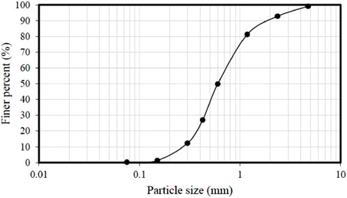
Figure 2. Grain size distribution of sand.
The corrugated steel pipe had a nominal inside diameter of 300 mm and a length of 455 mm. The pipes had a nominal wall thickness of 2 mm with a corrugation height of 15 mm and a corrugation length of 70 mm. Corrosion in the steel pipes was simulated by cutting out steel segments from areas that represent where water gets trapped between consecutive inner corrugation crests at the invert and cannot drain through the pipe. This simulation method was proposed by Rahmaninezhad et al. (2019). The trapped water increases the rate of corrosion in these areas and results in complete corrosion (Rahmaninezhad et al., 2019). The average cutout areas along the invert of two steel pipes were 50% and 90% to represent 50% and 90% degree of corrosion, respectively. These corrosion levels correspond to intact pipes (0%), moderately corroded pipes (50%), and severely deteriorated pipes approaching structural failure (90%). The PVC liners had an inside diameter of 254 mm, a wall thickness of 3 mm, and a length of 455 mm.
A low-viscosity grout was used for sliplining. The grout was able to flow through the space between the steel pipe and the liner easily. The mix of this grout included 254 kg/m3 cement, 384 kg/m3 fly ash, and 492 kg/m3 water. The unconfined compression tests were conducted on the grout specimens using the ASTM C39/C39M (2004) standard to determine their average 7-day compressive strength of 2.7 MPa.
The compressive strength of the grout was evaluated at 7 days instead of 28 days because rehabilitated pipes are typically subjected to traffic loads shortly after installation. This evaluation offers critical insights into the early-age performance of the grouted system, which is crucial for practical applications. Furthermore, due to the project’s scope and timeline, the study prioritized 7-day strength testing to deliver timely and relevant findings. Future studies could investigate the long-term strength development to complement this early-stage analysis.
The applied load was measured using an S-shape load cell with a load capacity of 22.3 kN mounted above the footing. A pressure gauge was used to control the hydraulic pressure applied to the footing. The settlement of the footing and the vertical and horizontal diameter changes of the liner were measured using two types of displacement transducers (DTs) with displacement limits of 100 mm and 50 mm, respectively. Pressure cells were used to measure vertical and lateral earth pressures.
A Totalcomp TS-B10-10K-SS S-beam load cell was used in this study to measure the applied load. The DTs employed were strain gauge-type sensors manufactured by Tokyo Sokki Kenkyujo Co., Ltd., Japan. Additionally, the pressure cells used to measure the vertical and lateral earth pressures were model KDG-PA/KDH-PA soil pressure gauges manufactured by TML, Japan.
Figure 3 shows the cross-section of the test setup including the locations of the footing, the load cell, the displacement transducers (DTs), and the pressure cells. The pipe was buried at a depth of 300 mm (from the surface to the top of the pipe) in each model test. A rigid plate was used to apply the load on the surface of the backfill. Two series of tests were conducted in this part of the study. The first series of tests, Series A, was conducted on the simulated corroded steel pipes without a liner as shown in Figure 3A. In these tests, the steel pipes had 0%, 50%, and 90% cutout, where the 0% cutout represents an intact steel pipe. In the second series of tests, Series B, three tests were carried out on sliplined steel pipes with 0%, 50%, and 90% cutout as shown in Figure 3B. In these tests, the liners were placed on the invert of the steel pipes. After each footing plate loading test, the pipe was exhumed from the soil for a parallel-plate loading test.
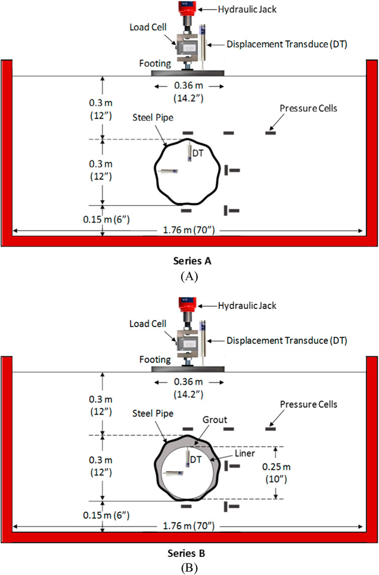
Figure 3. Test configurations: (A) Series A, unlined steel pipe and (B) Series B, sliplined steel pipe.
Each model was constructed in four lifts with a lift thickness of 150 mm in addition to a 150-mm-thick bedding layer underneath the pipe. After placement of each lift of the sand, it was compacted to a relative density of 75% using a mass-volume control method. Before placement of the steel pipe, the PVC liner was inserted into the pipe. Both ends of the steel pipe were sealed using foam to minimize the leakage of grout. After placement of the pipe, sand was placed around the pipe up to its springlines and the pressure cells were installed. Figure 4 shows the steel pipe, the liner, and two pressure cells. Additional sand was placed up to the pipe crown. To pour the grout into the annulus between the steel pipe and the liner, a 40-mm-diameter hole was drilled into the crown of the steel pipe and a PVC pipe of 40 mm in diameter and 0.4 m long was connected to the hole as a drop tube. After the installation of the tube, the last two lifts of sand were placed and compacted above the crown up to the surface.
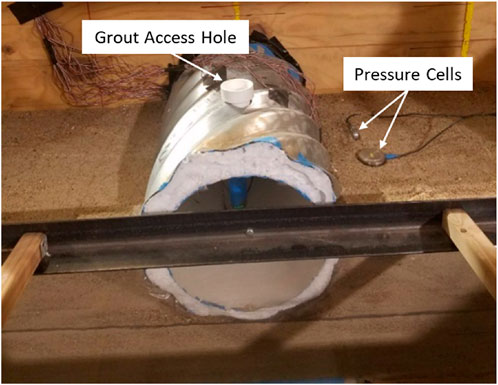
Figure 4. Placed steel pipe and liner.
After the model construction, the grouting process was started and completed in two stages to mitigate the buoyant force of the grout. The first stage of grouting reached the haunch level while the second stage of grouting filled the rest of the annulus. Figure 5 shows pouring of the grout into the annulus through a drop tube. During grouting, some grout leaked out through the cutout area and pipe ends into the bedding sand. The dotted line in Figure 6 shows the area where the grout leaked in the bedding sand. The volumes of the grout used for the pipes with 0%, 50%, and 90% cutout were 0.011, 0.013, and 0.015 m3. Upon the completion of two grouting stages, the model was left for 7 days for the grout in the annulus to set and cure.
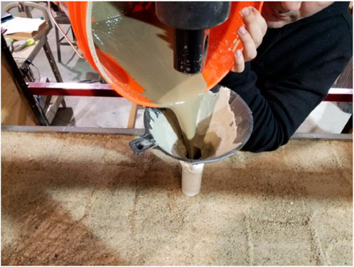
Figure 5. Pouring grout into the annulus through a drop tube.
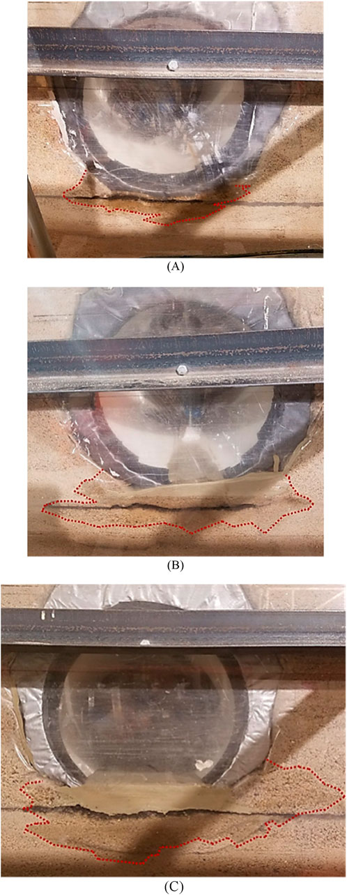
Figure 6. Leaked grout: (A) 0% cutout, (B) 50% cutout, and (C) 90% cutout.
A volume control method was employed to ensure the grout completely filled the annular space between the liner and the steel pipe. The volume of the gap was calculated prior to grouting, and an equivalent volume of grout was prepared. The grouting process was carefully monitored to ensure uniform filling. After curing, the pipes were exhumed and visually inspected to verify the effectiveness of the grout placement.
At 7 days after grouting, the soil surface was subjected to a static footing load. The load was applied in equal increments up to 140 kPa and then unloaded to zero. At each load increment, the plate settlement, the pipe deformations, and the pressures in the soil were measured by the sensors. These data were used to evaluate the performance of unlined and lined pipes at different degrees of cutout and the benefit of sliplining to the pipes buried in the soil. After the footing loading test, the pipe was exhumed from the soil for the parallel-plate loading test.
The universal testing machine with a load capacity of 530 kN was used to apply vertical loads on the exhumed rehabilitated steel pipes. To ensure uniform load distribution and avoid localized deformation in the corrugations during the parallel plate loading tests, rigid plates matching the length of the pipes were utilized. This setup ensured consistent load application along the entire length of the pipes. Post-test inspections of the sliplined and unlined pipes confirmed that no localized deformation occurred in the corrugations, further validating the effectiveness of this test approach.
The applied load was measured using an S-shape load cell with a load capacity of 40 kN. The vertical and horizontal diameter changes of the steel pipes and the liners were measured using two types of DTs with displacement limits of 100 and 50 mm.
Figure 7 shows the schematic cross-section of the test setup including the locations of the load cell and DT. On the top of the pipe, a rigid plate was used to apply the load to the pipe. A series of tests were conducted on the exhumed rehabilitated steel pipes. The exhumed steel pipes had 0%, 50%, and 90% cutout. Moreover, the liners in these tests were placed on the invert of the steel pipes.
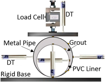
Figure 7. Test configurations.
The settlement of the footing at the center after each applied pressure was measured by the DT. Figure 8A shows the pressure-settlement curves of the footing on the backfill with the unlined steel pipes with 0%, 50%, and 90% cutout. The results show that the models with the pipes having 50% and 90% cutout had larger settlements than the model with the steel pipe without any cutout (0% cutout). When the applied pressure was lower than 125 kPa, the model with the pipe with 90% cutout behaved stiffer than that with 50% cutout. This phenomenon resulted from the fact the pipe with 90% cutout behaved like an arch (Rahmaninezhad et al., 2019). However, after 125 kPa, the model with the pipe with 50% cutout had smaller settlement than that with 90% cutout. Under the applied pressure of 140 kPa, the footing settlement in the models with the unlined steel pipes with 0%, 50%, and 90% cutout were 19, 33, and 35 mm, respectively.
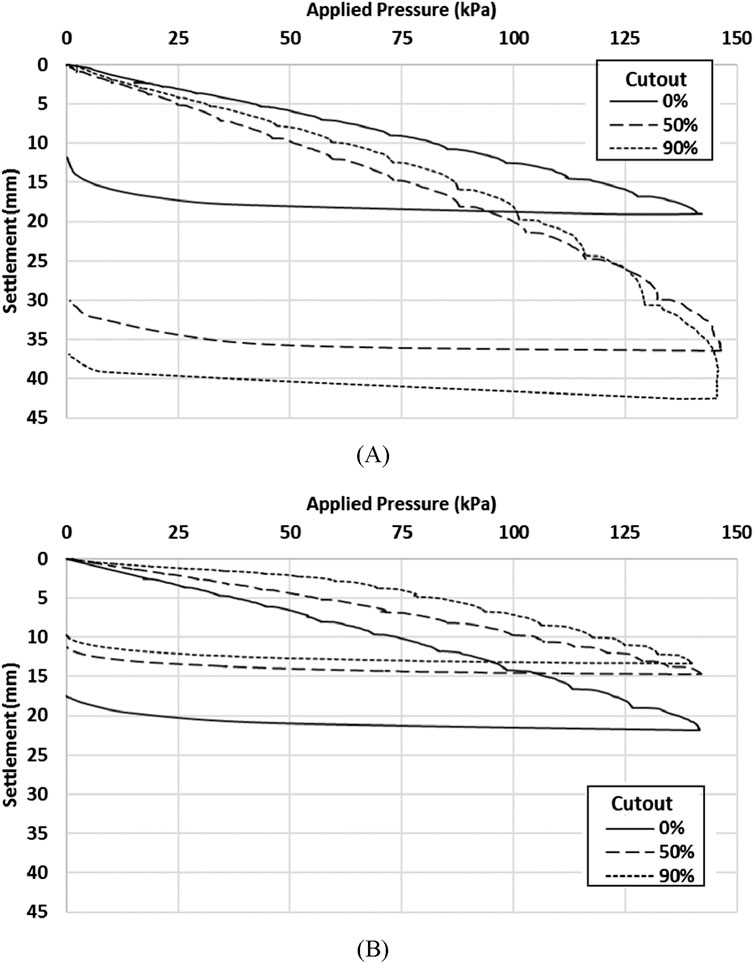
Figure 8. Pressure-settlement curves of the footings for the models: (A) with the unlined steel pipes in test Series A and (B) with the sliplined steel pipes in test Series B.
Figure 8B shows the pressure-settlement curves of the footing in the models with the sliplined steel pipes with 0%, 50%, and 90% cutout. The result shows that the model with the sliplined steel pipe with a lower degree of cutout had a lower load capacity than that with a higher degree of the cutout. This phenomenon likely resulted from the grout that leaked out into the bedding sand. The leaked grout made the bedding sand under the pipes with 90% and 50% cutout stronger than that under the pipe with 0% cutout. Moreover, because of the arching behavior of the pipe with 90% cutout, the model with this pipe behaved stiffer than that with the steel pipe with 50% cutout.
Our results demonstrate that sliplining increased the load-carrying capacities of corrugated steel pipes at different corrosion levels. This observation aligns with findings by Smith et al. (2015) and Tetreault et al. (2020), who reported significant improvements in the stiffness and strength of sliplined pipes. Additionally, our results indicate that the degree of corrosion impacts the effectiveness of sliplining, which complements Rahmaninezhad et al. (2019) and Hudson et al. (2023).
Figure 9 shows the applied load versus diameter change curves for the steel pipes. During loading, the distance between the crown and the invert decreased in the direction of the applied load. However, the distance between the springlines increased. Figure 9A shows that the unlined steel pipe with 0% cutout had a higher load capacity than the pipes with 50% and 90% cutout for Series A tests. The unlined steel pipes had outside vertical and horizontal diameter changes that were of approximately equal magnitude but with opposite signs. When the applied pressure was lower than 115 kPa, the steel pipe with 90% cutout had less vertical diameter change than the pipe with 50% cutout. However, above 115 kPa, the pipe with 50% cutout had smaller vertical diameter changes than the pipe with 90% cutout while the steel pipe with 90% cutout had smaller horizontal diameter changes than the pipe with 50% cutout. This phenomenon resulted from the fact that the pipe with 90% cutout behaved like an arch with a flat base (Rahmaninezhad et al., 2019).
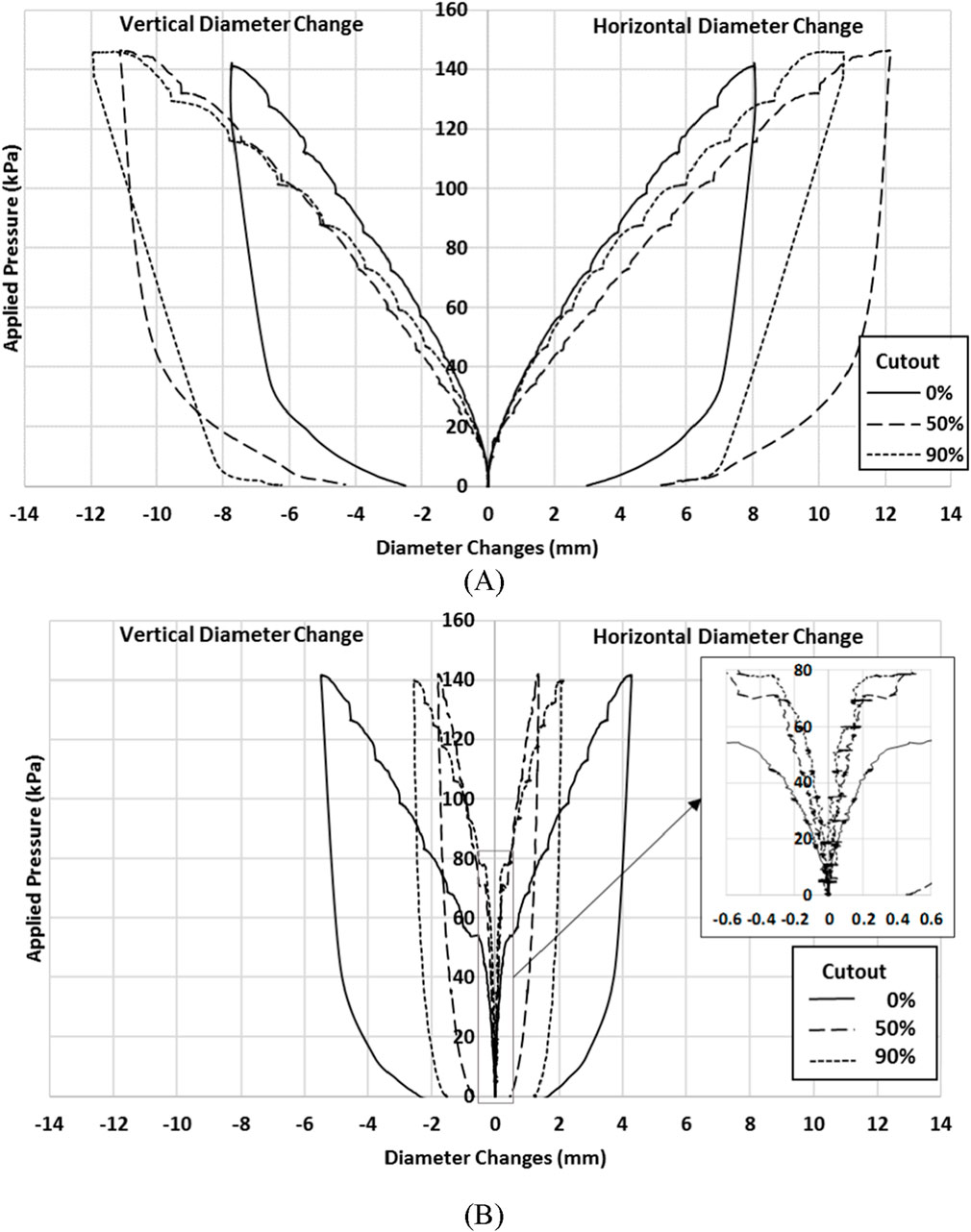
Figure 9. Applied load versus vertical and horizontal diameter changes: (A) for test Series A and (B) for test Series B.
In Figure 9B shows that the sliplined steel pipe with 50% cutout had a higher load capacity than the pipes with 0% and 90% cutout. The sliplined steel pipes had larger vertical diameter changes than horizontal diameter changes at the same applied load. When the applied pressure was lower than 90 kPa, the steel pipe with 90% cutout behaved stiffer than the pipe with 50% cutout. However, above 90 kPa, the pipe with 50% cutout behaved stiffer than the pipe with 90% cutout. Figure 9 indicates that sliplining reduced the diameter changes of the unlined steel pipes. For instance, under the applied pressure of 130 kPa, the vertical diameter changes of the steel pipes with 0%, 50%, and 90% cutout after sliplining were 1.5, 5.6, and 5.3 times, respectively—less than those before sliplining.
Ovality, defined as the relative deformation of the steel pipe and liner’s cross-section under loading, is a critical parameter for evaluating the performance of buried liners (Vazouras et al., 2010; Jalali et al., 2016). While this study focused on load-carrying capacity and stiffness, ovality was not measured during the tests. Future studies could incorporate ovality measurements to provide a more comprehensive understanding of the liner’s deformation behavior under footing loading.
Figure 10 presents the vertical earth pressures induced by footing loading around the unlined steel pipes for test Series A. The locations of the earth pressure cells (EPCs) are shown in this figure. It should be noted that the measured earth pressures are the additional pressures induced by footing loading and do not include the pressure due to the soil self-weight. The measured vertical earth pressures generally increased with the increase of the applied footing pressure for the unlined steel pipes. These results indicate that in the models with the unlined steel pipes, EPC6 measured higher pressures than EPC7 at the same applied pressure. The measured pressures from EPC1 and EPC6, which were placed under and above the unlined steel pipe with 0% cutout, respectively, were higher than those with 50% and 90% cutout. Moreover, in these tests, the measured pressure from EPC6 was higher than that from EPC1. For example, in the model with the pipe having 0% cutout, the measured pressure from EPC6 was approximately three times that from EPC1. However, at the same applied pressure, the measured pressures from EPC2, EPC5, and EPC7 were approximately equal. This phenomenon resulted from the fact that the model with the unlined steel pipe having 0% cutout had higher stiffness than those having 50% and 90% cutout as shown in Figure 8A. Since some segments were cut out along the invert of the steel pipes with 50% and 90% of the material removed to simulate corrosion, the measured pressure from EPC1 was lower than that from EPC2. However, in the model with the unlined steel pipe with 0% cutout, the measured pressure from EPC1 was higher than that from EPC2.
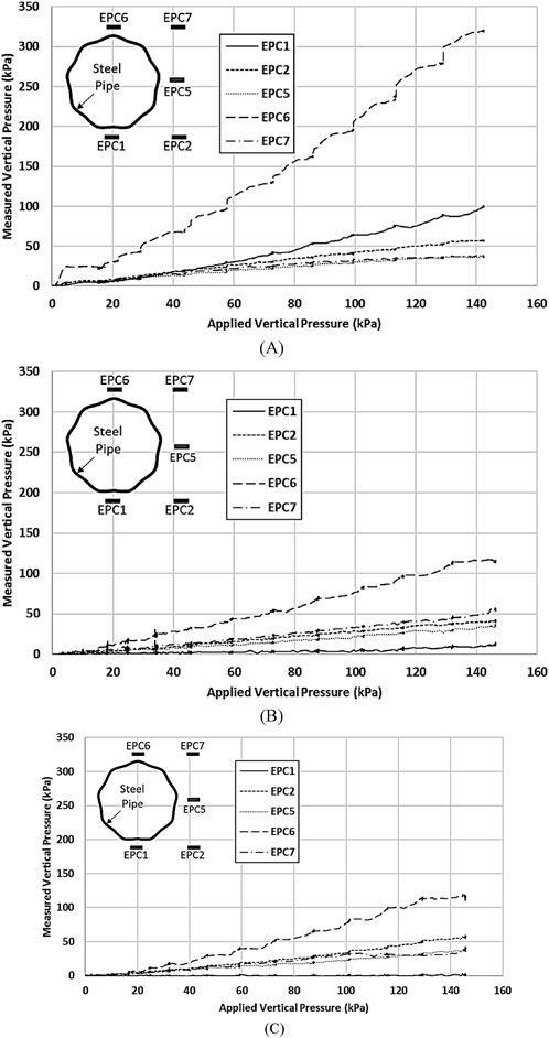
Figure 10. Measured vertical pressures around the unlined pipe in test Series A with: (A) 0%; (B) 50%; and (C) 90% cutout.
Figure 11 shows the vertical earth pressures induced by footing loading around the sliplined steel pipes for Series B tests. The results indicate that EPC6 in the backfill with the sliplined steel pipes measured a higher pressure than EPC7 at the same applied pressure. In the model with the sliplined steel pipe having 0% cutout, the measured pressures from EPC1 and EPC6 were approximately equal, as shown in Figure 11A. However, in the models with the sliplined steel pipe having 50% and 90% cutout, EPC6 measured a higher pressure than EPC1 at the same applied pressure. In the models with the sliplined steel pipe having 90% cutout, Figure 11C shows a reduction on the measured pressure from EPC1 when the applied pressure was 78 kPa. At the same applied pressure, the measured pressures from EPC2, EPC5, and EPC7 were approximately equal.
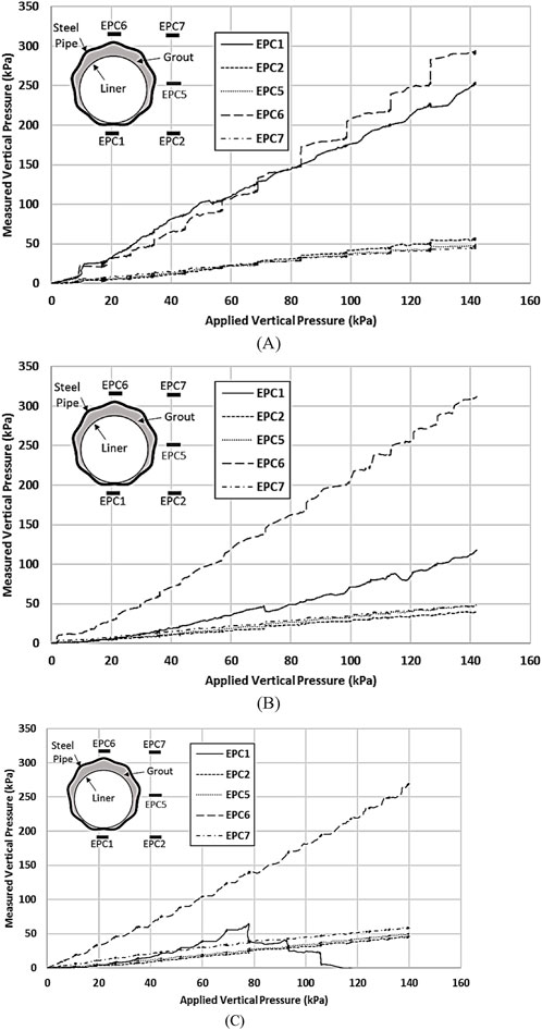
Figure 11. Measured vertical pressures around the sliplined pipes in test Series B with: (A) 0%; (B) 50%; and (C) 90% cutout.
The measured earth pressures induced by footing loading above the crown of unlined pipes with 0% cutout were higher than those with 50% and 90% cutout. These findings are consistent with the trends observed by Simpson et al. (2016) and Peter and Moore (2019), who reported similar influences of structural deterioration on stress distribution.
Figure 12 shows the lateral earth pressures induced by footing loading around the unlined steel pipes for test Series A. The results indicate that the measured lateral pressures in the model with the unlined steel pipe having 0% cutout were higher than those with 50% and 90% cutout. This is because the unlined steel pipe having 0% cutout was more rigid than other two pipes, it helped transfer more vertical load to the bottom of the pipe as shown in Figure 10 so that the lateral pressure was higher in the 0% cutout case. Figure 12 also shows that EPC3 generally measured higher pressures than EPC4. This is also because the measured vertical pressures at the bottom of the pipe were higher than those at the springline of the pipe as shown in Figure 10.
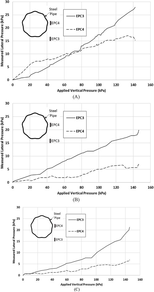
Figure 12. Measured lateral pressures around the unlined pipes in test Series A with: (A) 0%; (B) 50%; and (C) 90% cutout.
Figure 13 shows the lateral earth pressures induced by footing loading around the sliplined steel pipes for test Series B. The results show that regardless of the percentage of the cutout, the measured lateral pressures from EPC3 were higher than those from EPC4. The measured lateral pressures from EPC3 in the models with the sliplined pipes having 0% and 90% cutout and under the same applied pressure were approximately equal, as shown in Figures 12A, B. However, the measured pressures from EPC4 in the model with the sliplined pipe having 0% cutout were higher than those having 50% cutout. In the model with the unlined steel pipe having 90% cutout, when the applied pressure was lower than 56 kPa, the measured pressures from EPC3 and EPC4 were approximately equal, as shown in Figure 13C. However, when the applied pressure was higher than 56 kPa, EPC3 measured higher pressures than EPC4. Moreover, in the model with the sliplined steel pipe having 90% cutout, the measured pressures from EPC4 were lower than those in the model with the sliplined steel pipe having 50% cutout.
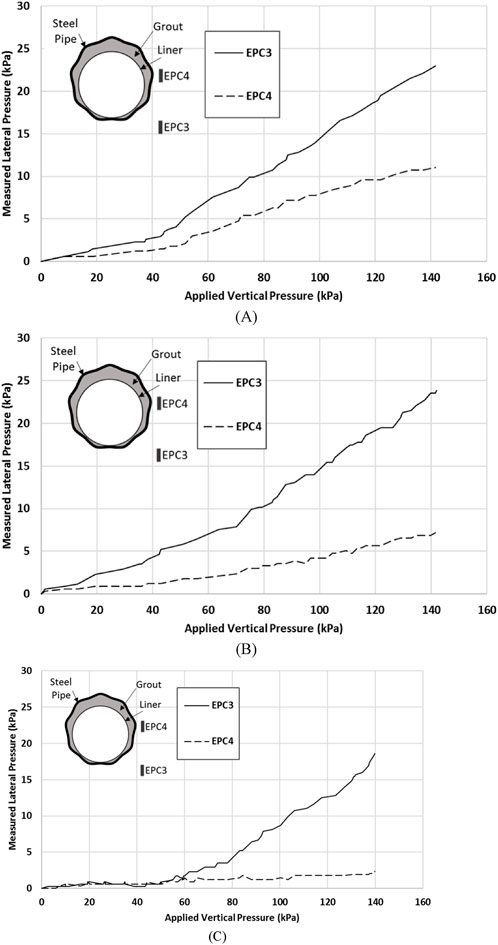
Figure 13. Measured lateral pressures around the sliplined pipes in test Series B with: (A) 0%; (B) 50%; and (C) 90% cutout.
For the sliplined pipes, the strengthening effects of the grout and the enhanced load distribution capacity contributed to higher lateral pressures at EPC3 compared to EPC4, regardless of the cutout percentage. The pipe with 0% cutout exhibited higher pressures at EPC4 relative to the 50% cutout pipe, likely due to the grout-induced strengthening of the bedding sand beneath the larger cutout areas. The 90% cutout pipe displayed arching behavior under lower applied pressures, redistributing stresses and reducing pressures near EPC4. At higher pressures, the strengthened bedding sand transferred greater lateral stresses to EPC3. These findings underscore the importance of both the degree of pipe deterioration and the structural benefits introduced by sliplining in modifying lateral pressure distributions.
Figure 14 shows the applied load versus the vertical and horizontal outside diameter changes of the exhumed pipes that were measured by DTs installed outside the sliplined pipes. The results indicate that the sliplined pipes with 50% and 90% cutout behaved stiffer than the pipe with 0% cutout. Also, the vertical diameter changes of the sliplined pipes with 50% and 90% cutout were similar. However, the sliplined pipe with 50% cutout had smaller horizontal diameter changes than that with 90% cutout at the same applied load. The sliplined steel pipes with 0% and 50% cutout had vertical outside diameter changes of larger magnitude and opposite sign than the horizontal diameter changes. However, the pipe with 90% cutout had smaller vertical outside diameter changes than horizontal outside diameter changes. Figure 14 indicates that sliplining increased the load-carrying capacity of the unlined steel pipes. For instance, at 5% vertical diameter change, the load-carrying capacities of the steel pipes with 0%, 50%, and 90% cutout were increased by 1.4, 2.9, and 2.6 times, respectively.
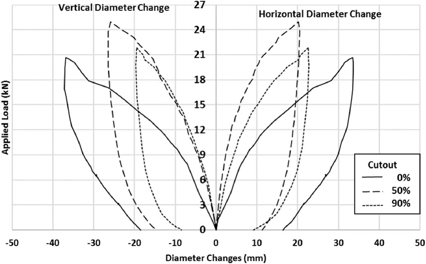
Figure 14. Applied load versus vertical and horizontal outside diameter changes.
The parallel plate tests in this study differ from the previous work (Rahmaninezhad et al., 2019) in two key aspects: (1) the grout used here had a significantly higher 7-day compressive strength (2.7 MPa) compared to the low-strength grout (249 kPa) used previously, and (2) the grout was introduced into the space between the steel pipe and the liner when the pipe was placed horizontally in the soil while the grout was introduced when the pipe was placed vertically in air in the previous study. As a result, the lined pipes in this study had stiffer responses than those in the previous study (Rahmaninezhad et al., 2019).
This paper presents footing loading tests on unlined and sliplined steel pipes with different degrees of corrosion in soil and parallel-plate loading tests of exhumed pipes in air. The following conclusions can be made from this study:
The models with the unlined pipes having 50% and 90% cutout had larger settlement than the model with the steel pipe having 0% cutout. Under the lower applied pressures, the model with the unlined pipe having 90% cutout had smaller settlement and vertical diameter changes than those having 50% cutout. The unlined steel pipe with 90% cutout had smaller horizontal diameter changes than the pipe with 50% cutout.
The model with the sliplined steel pipe having a smaller percentage of cutout had a lower load capacity and higher footing settlement than that having a larger percentage of the cutout because the leaked grout made the bedding sand stronger under the pipe with a larger percentage of cutout stronger than that with a smaller percentage of cutout. Due to the arch behavior of the pipe with 90% cutout, the model with this pipe had higher stiffness than the steel pipe with 50% cutout. Under the lower applied pressures, the sliplined steel pipe with 90% cutout had higher stiffness than the unlined pipes with 50% and 90% cutout.
The results indicate that sliplining increased the load-carrying capacities of the unlined steel pipes by 1.4, 2.9, and 2.6 times for pipes with 0%, 50%, and 90% cutout, respectively, under a 5% vertical diameter change conditioner an applied pressure of 130 kPa, the vertical diameter changes of the sliplined pipes were reduced by factors of 1.5, 5.6, and 5.3 for pipes with 0%, 50%, and 90% cutout compared to the unlined pipes.
The settlement for unlined steel pipes under a pressure of 140 kPa was measured as 19 mm, 33 mm, and 35 mm for pipes with 0%, 50%, and 90% cutout, respectively.
The measured earth pressures induced by footing loading above the crown of the unlined pipe with 0% cutout were higher than those with 50% and 90% cutout.
The measured vertical pressures under the invert and above the crown of the sliplined steel pipe with 0% cutout were approximately equal. However, the measured vertical pressures above the crown of the sliplined steel pipes with 50% and 90% cutout were higher pressures than those under the invert.
The measured lateral pressures in the backfill with the unlined steel pipes having 0% cutout were higher than those having larger percentages of cutout. The measured lateral pressures at the level of the invert of the sliplined pipes were higher than those at the level of the springline.
In the parallel-plate loading tests on the exhumed pipes, the sliplined pipes with 50% and 90% cutout behaved stiffer than the sliplined pipe with 0% cutout. The vertical diameter changes of the sliplined pipes with 50% and 90% cutout were similar. Sliplining increased the load-carrying capacities of the unlined steel pipes.
The original contributions presented in the study are included in the article, further inquiries can be directed to the corresponding author.
SR: Data curation, Formal Analysis, Investigation, Methodology, Validation, Writing–original draft. SJ: Formal Analysis, Investigation, Writing–review and editing, Data curation. JH: Formal Analysis, Investigation, Writing–review and editing, Conceptualization, Funding acquisition, Methodology, Resources, Supervision. MA-N: Data curation, Investigation, Writing–review and editing. RP: Data curation, Funding acquisition, Investigation, Writing–review and editing.
The author(s) declare that financial support was received for the research, authorship, and/or publication of this article. This research project was financially sponsored by the Kansas Department of Transportation (DOT).
Mr. Dave Meggers, late chief of the KDOT Bureau of Research, was the project monitor. Contech Engineered Solutions LLC provided the steel pipes used in the experimental tests and Mr. Bill Gonsalez, the Territory Sales Representative, provided great assistance in this study. The laboratory managers, Mr. David Woody and Mr. Kent Dye, in the Department of Civil, Environmental, and Architectural Engineering (CEAE) at the University of Kansas (KU) provided their laboratory support.
Author SR was employed by Terracon Consulting Inc.
The remaining authors declare that the research was conducted in the absence of any commercial or financial relationships that could be construed as a potential conflict of interest.
The author(s) declared that they were an editorial board member of Frontiers, at the time of submission. This had no impact on the peer review process and the final decision.
The author(s) declare that no Generative AI was used in the creation of this manuscript.
All claims expressed in this article are solely those of the authors and do not necessarily represent those of their affiliated organizations, or those of the publisher, the editors and the reviewers. Any product that may be evaluated in this article, or claim that may be made by its manufacturer, is not guaranteed or endorsed by the publisher.
Acharya, R., Han, J., Brennan, J. J., Parsons, R. L., and Khatri, D. K. (2016). Structural response of a low-fill box culvert under static and traffic loading. J. Perform. Constr. Facil. 30 (1), 04014184. doi:10.1061/(asce)cf.1943-5509.0000690
Al-Naddaf, M., Han, J., Xu, C., and Rahmaninezhad, S. M. (2019). Effect of geofoam on vertical stress distribution on buried structures subjected to static and cyclic footing loads. J. Pipeline Syst. Eng. Pract. 10 (1), 04018027. doi:10.1061/(asce)ps.1949-1204.0000355
Arjun, M., Kaushal, V., Shirkhanloo, S., Rahman, S., and Najafi, M. (2023). A review of rehabilitation methods for aging pipe culverts by spray applied pipe lining, grouting, and sliplining. Pipelines, 252–259. doi:10.1061/9780784485026.027
ASTM C39/C39M-04 (2004). Standard test method for compressive strength of cylindrical concrete specimens. West Conshohocken, PA: ASTM International.
ASTM D3080/D3080M-11 (2011). Standard test method for direct shear test of soils under consolidated drained conditions. West Conshohocken, PA: ASTM International.
Ballinger, C. A., and Drake, P. G. (1995). Culvert repair practices manual: volume I (Report No. FHWA-RD-94-096). McLean, VA: Federal Highway Administration.
Bloomquist, D., Boyd, A., Chen, Y., and Crosby, M. (2009). Load response comparison between fiber and steel reinforced concrete pipe – phase two. Tallahassee, FL: Florida Department of Transportation.
Bryden, C., and Valsangkar, A. (2025). Long-term design life assessment of a corrugated steel pipe culvert rehabilitated with geopolymer liner. J. Struct. Des. Constr. Pract. 30 (2), 06024006. doi:10.1061/jsdccc.sceng-1537
Han, J., Rahmaninezhad, S. M., Al-Naddaf, M., Parsons, R. L., Jawad, S., and Liu, H. (2019). Grouting Effects on Performance of sliplined steel pipes No. K-TRAN: KU-17-3.
Han, J., Rahmaninezhad, S. M., Parsons, R. L., and Wang, F. (2018). Software for load distribution on low-fill box culverts: user’s manual. Kans. Dept. Transp.
Hudson, J. A., Cardenas, H., Matthews, J., and Alam, S. (2023). Performance evaluation of deteriorated and rehabilitated corrugated metal pipe culverts using multiphysics simulation. Tunn. Undergr. Space Technol. 131, 104827. doi:10.1016/j.tust.2022.104827
Jalali, H. H., Rofooei, F. R., Attari, N. K. A., and Samadian, M. (2016). Experimental and finite element study of the reverse faulting effects on buried continuous steel gas pipelines. Soil Dyn. Earthq. Eng. 86, 1–14. doi:10.1016/j.soildyn.2016.04.006
Jawad, S., Al-Naddaf, M., Han, J., and Rahmaninezhad, S. M. (2024). Effects of spray-on lining rehabilitation on behavior of buried corroded metal pipes subjected to surface loading. J. Pipeline Syst. Eng. Pract. 15 (1), 04023055. doi:10.1061/jpsea2.pseng-1435
Kouchesfehani, Z. K., Tehrani, A. D., and Najafi, M. (2021). Culvert renewal with cementitious-geopolymer spray–applied pipe lining: field data collection and assessment. J. Pipeline Syst. Eng. Pract. 12 (3), 04021028. doi:10.1061/(asce)ps.1949-1204.0000555
Kouchesfehani, Z. K., Tehrani, A. D., Najafi, M., and Syar, J. (2020). Laboratory testing of invert-cut corrugated metal pipes renewed with polymeric spray applied pipe lining. Transp. Geotech. 25, 100413. doi:10.1016/j.trgeo.2020.100413
Mai, V. T. (2013). Assessment of deteriorated corrugated steel culverts (Master’s thesis). Kingston, Ontario: Queen’s University.
Mai, V. T., Hoult, N. A., and Moore, I. D. (2014). Effect of deterioration on the performance of corrugated steel culverts. J. Geotechnical Geoenvironmental Eng. 140 (2), 04013007. doi:10.1061/(asce)gt.1943-5606.0001021
Peter, J. M., and Moore, I. D. (2019). Effects of erosion void on deteriorated metal culvert before and after repair with grouted slip liner. J. Pipeline Syst. Eng. Pract. 10 (4), 04019031. doi:10.1061/(asce)ps.1949-1204.0000399
Rahmaninezhad, S. M., Han, J., Al-Naddaf, M., Jawad, S., Parsons, R. L., and Liu, H. (2020). Field evaluation of performance of corroded corrugated steel pipe before and after sliplining rehabilitation. Tunn. Undergr. Space Technol. 102, 103442. doi:10.1016/j.tust.2020.103442
Rahmaninezhad, S. M., Han, J., Al-Naddaf, M., and Parsons, R. L. (2019). Behavior of sliplined corrugated steel pipes under parallel-plate loading. J. Mater. Civ. Eng. 31 (10), 04019242. doi:10.1061/(asce)mt.1943-5533.0002889
Raut, S., Azizian, M., Chimauriya, H. R., Tehrani, A. D., Najafi, M., and Yu, X. (2024). Three-dimensional finite element modeling of spray-applied pipe liners repaired corrugated metal pipes buried under shallow cover. Transp. Res. Rec., 03611981241230534. doi:10.1177/03611981241230534
Safari, S., DuBose, T., Head, M. H., Shenton III, H. W., Tatar, J., Chajes, M. J., et al. (2024). Diagnostic load testing and assessment of a corroded corrugated metal pipe culvert before rehabilitation. Struct. Infrastructure Eng. 20 (7-8), 1149–1158. doi:10.1080/15732479.2023.2280053
Simpson, B., Hoult, N. A., and Moore, I. D. (2017). Rehabilitated reinforced concrete culvert performance under surface loading. Tunn. Undergr. Space Technol. 69, 52–63. doi:10.1016/j.tust.2017.06.007
Simpson, B., Moore, I. D., and Hoult, N. A. (2016). Experimental investigation of rehabilitated steel culvert performance under static surface loading. J. Geotechnical Geoenvironmental Eng. 142 (2), 04015076. doi:10.1061/(asce)gt.1943-5606.0001406
Smith, T., Hoult, N. A., and Moore, I. D. (2015). Role of grout strength and liners on the performance of slip-lined pipes. J. Pipeline Syst. Eng. Pract. 6 (4), 04015007. doi:10.1061/(asce)ps.1949-1204.0000203
Tetreault, J., Moore, I. D., and Hoult, N. A. (2020). Laboratory study on effect of grout choice on culvert rehabilitation using sliplining. J. Pipeline Syst. Eng. Pract. 11 (1), 04019044. doi:10.1061/(asce)ps.1949-1204.0000420
Vazouras, P., Karamanos, S. A., and Dakoulas, P. (2010). Finite element analysis of buried steel pipelines under strike-slip fault displacements. Soil Dyn. Earthq. Eng. 30 (11), 1361–1376. doi:10.1016/j.soildyn.2010.06.011
Wang, F., Han, J., Khatri, D. K., Parsons, R. L., Brennan, J. J., and Guo, J. (2016). Field installation effect on steel-reinforced high-density polyethylene pipes. J. Pipeline Syst. Eng. Pract. 7 (1), 04015013. doi:10.1061/(asce)ps.1949-1204.0000211
Keywords: buried pipe, corrosion, corrugated steel pipe, grouting, PVC liner, rehabilitation, sliplining
Citation: Rahmaninezhad SM, Jawad S, Han J, Al-Naddaf M and Parsons RL (2025) Behavior of buried sliplined corrugated metal pipes subjected to footing loading. Front. Built Environ. 11:1532485. doi: 10.3389/fbuil.2025.1532485
Received: 22 November 2024; Accepted: 13 February 2025;
Published: 12 March 2025.
Edited by:
Fei Wang, Mississippi State University, United StatesReviewed by:
Weibin Chen, University of Macau, ChinaCopyright © 2025 Rahmaninezhad, Jawad, Han, Al-Naddaf and Parsons. This is an open-access article distributed under the terms of the Creative Commons Attribution License (CC BY). The use, distribution or reproduction in other forums is permitted, provided the original author(s) and the copyright owner(s) are credited and that the original publication in this journal is cited, in accordance with accepted academic practice. No use, distribution or reproduction is permitted which does not comply with these terms.
*Correspondence: Jie Han, amllaGFuQGt1LmVkdQ==
Disclaimer: All claims expressed in this article are solely those of the authors and do not necessarily represent those of their affiliated organizations, or those of the publisher, the editors and the reviewers. Any product that may be evaluated in this article or claim that may be made by its manufacturer is not guaranteed or endorsed by the publisher.
Research integrity at Frontiers
Learn more about the work of our research integrity team to safeguard the quality of each article we publish.