 John Xin Wang
 Richard Kwok Kit Yuen
 Lan Wang2
94% of researchers rate our articles as excellent or good
Learn more about the work of our research integrity team to safeguard the quality of each article we publish.
Find out more
ORIGINAL RESEARCH article
Front. Built Environ., 08 April 2025
Sec. Urban Science
Volume 11 - 2025 | https://doi.org/10.3389/fbuil.2025.1525361
This article is part of the Research TopicIntelligence and Big Data for Sustainable Urban Built EnvironmentView all 5 articles
Urban ventilation study using the computation fluid dynamics (CFD) approach plays an important role in alleviating the urbanization challenges of high energy consumption, human comfort, and public health in an urban built environment. Grid arrangement is a critical step for such CFD applications. The grid amount and quality can significantly influence the accuracy, convergence, and computational efficiency. In this study, an innovative hybrid grid generation strategy is proposed for urban ventilation simulation. This strategy aims to strike a balance between capturing the intricate details of the flow and minimizing the computational burden associated with a large number of grids. The proposed hybrid grid algorithm characterizes an octree-based Cartesian grid dominating the computational domain, mixing with a tetrahedral grid close to the building surfaces. The performance of this hybrid grid scheme is tested with an example of a single high-rise residential building, and a significant reduction of up to 98% in the number of grids is achieved for the hybrid grid scheme compared to the all-tetrahedral grid scheme. The multiple buildings example shows that this proposed grid generation can expand to general urban-scale built environment applications. Finally, a case study with the hybrid grid arrangement is carried out to validate the simulation results with experimental measurement data. The proposed hybrid grid generation in this study offers an efficient and reliable approach to simulate urban ventilation by an automatic grid generation process. This highly efficient grid arrangement can shorten the design turnaround and contribute to integration into big data for urban built environments with efficient data storage and data processing.
With rapid urban development, citizens living in urban cities have encountered sustainable development challenges in terms of high energy consumption, human comfort, and public health due to the high density of building structures and urban population (Smith and Levermore, 2008). Airflow within an urban built environment plays an important role in effectively alleviating the challenges (Razak et al., 2013). Computation fluid dynamics (CFD) has become an attractive tool for studying urban ventilation in the building industry based on the establishment of research on CFD theory in the past decades, including techniques on the turbulence models, discretization methods, and boundary conditions. (Launder and Spalding, 1972; Patankar, 1980; Murakami and Mochida, 1988; Versteeg and Malalasekera, 1995). Nowadays, the demand for CFD applications on large-scale urban wind simulation with industrial-level complexity has been increasing for sustainable built environment development. In addition, with the trend of deeper building digitalization advancement, the numerical wind field data generated by CFD simulation can be incorporated as a critical component into a cloud-based big data system together with various multidiscipline data for data-driven design processes (Kosicki et al., 2022). However, the amount of CFD data is normally quite large, with up to gigabytes of data compared to megabytes of CAD geometry data, which hinders the data processing efficiency in a big data system for an urban built environment.
Grid generation is a crucial step of CFD simulation as it creates a discrete representation of the physical domain within which the numerical simulation will take place. The grid amount and quality can significantly influence the accuracy, convergence, and computational efficiency of the simulation. A desirable grid system for urban ventilation simulation must be: (1) capable of fitting the complicated geometry boundaries with good grid quality, (2) flexible on local refinements, (3) highly efficient on the number of grids used for domain discretization spatially, and (4) highly automatic during the grid generation process. On the one hand, CFD practitioners stated that grid generation is considered a difficult task during the whole CFD application process. On the other hand, the number of grids used for simulation directly determines the size of the dataset produced by the simulation solver. Therefore, it is worth investigating the grid generation strategy for urban ventilation applications to improve simulation efficiency, accuracy, and contribution to big data development for urban built environments.
Structured and unstructured grids are widely used in CFD simulations. Structured grids are characterized by a regular and ordered arrangement of cells. They are typically composed of hexahedral elements in three dimensions and are straightforward to index and manipulate. This regularity simplifies the implementation of numerical algorithms and can lead to efficient computations. However, they are less suitable for complex geometries with irregular shapes or multiple connected domains. Common methods used for structured grid generation contain mapped meshing (Thompson et al., 1985; Knupp and Steinberg, 1995), block decomposition (Tam and Armstrong, 1993; Price and Armstrong, 1995; Price and Armstrong, 1997), superposition (Schneiders, 1996; Taghavi, 1994; Ives, 1995), and the dual method (Mitchell, 1996; Muller-Hannemann et al., 1999; Calvo and Idelsohn, 2000). Unstructured grids, on the other hand, consist of cells of various shapes, such as tetrahedrons or polyhedrons in three dimensions. They offer greater flexibility in handling complex geometries but require complex data storage and management. Common methods for tetrahedral grid generation include point insertion (Shewchuk, 1997; Hang, 2010; Liu et al., 2014), advancing front (Lohner and Parikh, 1988; Rassineux, 1998), and octree (Shephard and Georges, 1991).
Yang et al. (2006) conducted natural ventilation simulations on a standard 6 m cube with coupled indoor and outdoor airflows using an all-tetrahedral mesh. The mesh scheme employed local refinements on the building surfaces and edges. This small-size cube case required generating 0.93–1.45 million grid elements. Tong et al. (2016) conducted neighborhood-scale CFD simulations for natural ventilation design with coupled indoor and outdoor domains. The target building size is a 10-m cube with up to four layers of neighbor buildings, and 2–11 million unstructured cells are used in the study. Huang et al. (2007) used a hybrid grid arrangement for CFD simulations of wind effects on a tall steel building with dimensions of 30.8 m × 45.72 m × 183.88 m. In the study, a virtual rectangular cylinder approximately four times larger than the building itself is defined. For zones inside the rectangular cylinder, an unstructured tetrahedral mesh is generated, while for zones outside the rectangular cylinder, the structured hexahedral mesh is applied. It is noted that the user must define the rectangle cylinder manually to decompose the domain, and the size of the rectangular cylinder is not optimized. The number of mesh elements generated is 1.2–3.5 million. Zhang et al. (2011) proposed an adaptive hexahedral-dominant mesh generation approach for natural ventilation simulations on a retrofit building with sharp geometry features. The study showed the mesh scheme can contribute to higher efficiency in the number of cell elements (0.38 million) for domain discretization. However, the boundary fitting is troublesome, as stated by the authors, and sharp features in non-manifold geometry models must be handled in future works. Fallahpour et al. (2024) conducted a parametric study of wind-driven natural ventilation for a single-floor simple cuboid. A hexahedral grid scheme is adopted, and the number of grid elements is ranged from 0.13 to 0.61 million.
The previous works indicate that grid arrangements for CFD wind simulation include the employment of tetrahedral grids, hexahedral grids, and combined grids. The tetrahedral grid shows high flexibility for local grid refinement for building surfaces, but it results in more grid elements generated than the structured grid system. The hexahedral grid has high efficiency on domain discretization, but complicated boundary fitting with good grid quality is a difficult task. The combined hybrid grid arrangement is attractive due to the incorporated merits of both the tetrahedral and hexahedral grids. However, the hybrid grid scheme is rarely used for large-scale urban built environments because the difficulty of manual domain decomposition increases significantly when moving from a single building to a cluster of buildings. Therefore, this study proposes an innovative automatic hybrid grid generation algorithm designed to address the challenges of hybrid grid generation for urban ventilation simulation. It aims to strike a balance between capturing the intricate details of the flow and minimizing the computational burden associated with a large number of grids. Using the proposed hybrid grid generation approach, the computational speed in the CFD solver would be increased, and the design turnaround would be shortened significantly. Moreover, the CFD simulation data based on this hybrid grid system can contribute to the efficient construction of big data for urban built environments because the size of the produced dataset is reduced dramatically with no compromise of the simulation accuracy.
The CFD simulation for urban ventilation study normally covers domains of hundreds of meters to several kilometers with multiple buildings and topography features. Spatial discretization of such models is a difficult task in the grid generation process because the grid size setting must vary remarkably within the domain. For example, the grid size near the building geometries may be set as 10−2 ∼ 10−1 m to reasonably represent the studied building boundary features, while it can be as large as 10∼102 m for the outer flow region far away from the buildings. In addition to the local grid refinement near the building geometries, vertical grid refinement along the height (Z) direction is required to accurately reproduce the wind profile in the atmospheric boundary layer.
The hybrid grid arrangement provides a suitable method of satisfying the various requirements of the grid system for urban-scale ventilation simulation by using a regular orthogonal grid in the outer region of a domain far away from the building geometry and a tetrahedral grid close to the building geometry. In this study, an innovative hybrid grid generation is presented by incorporating the merits of both structured and unstructured grid systems with efficient spatial discretization and flexibility to fit complex geometries. The overall structure of the hybrid grid generation process is illustrated in Figure 1.
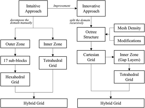
Figure 1. The overall structure of the hybrid grid generation process.
Take a computational domain with an arbitrary single building as an example. An intuitive approach for a hybrid grid scheme is first to decompose the domain into two zones, with one inner zone bounded by the building and another zone named the outer zone. Second, the outer zone is further decomposed into various sub-domains and employs a structured hexahedral grid in each sub-domain with the same grid resolution at the interface between two sub-domains. Third, the tetrahedral grid in the inner zone is filled in. An illustration of such a hybrid grid scheme is shown in Figure 2.

Figure 2. The intuitive approach for the hybrid grid arrangement.
The intuitive approach for hybrid grid arrangement is simple and straightforward. However, it requires much manual effort on domain decomposition for the outer zone, and the size of the inner zone is determined in an experience-based way by the user such that the number of tetrahedral grid elements in the inner zone is not minimized. Especially when the studied domain covers multiple buildings in an urban environment, it is difficult to decompose the domain manually for each building. A desirable approach is to generate grids automatically with zero manual involvement and a minimized inner zone. In this study, an improved and innovative approach is presented with an octree-based Cartesian grid generation method in contrast to the intuitive approach. This approach first discretizes the domain with Cartesian grid elements recursively by an octree data structure until the preliminary grid size requirements are satisfied. Second, a gap space is defined to bound building surfaces as the minimized inner zone. Third, a tetrahedral grid is employed in the gap space. A comparison between the octree-based method and the intuitive manual decomposition method is shown in Figure 3.
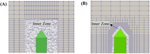
Figure 3. A comparison between the intuitive method (A) and the innovative method (B).
Octree is a tree data structure that can be used to divide a domain by recursively splitting it into eight octants, called child nodes. Each child node is defined as having a connection to its parent. A node without child nodes is called a leaf node and represents one Cartesian grid element. At the beginning stage, the octree has only a root node, which is generated to cover the domain, and the root node level is defined as 0. The next step is to define the initial maximum node level in the octree and the node level for the nodes intersecting with the building surfaces. Finally, the octree-based algorithm can run recursively until the defined node level is reached, as shown in Figure 4.
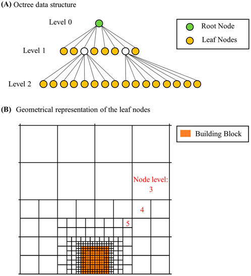
Figure 4. A demonstration of the octree data structure (A) and a geometrical representation of the leaf nodes (B).
The octree structure with a 2:1 balance is defined as having a node level difference between two neighbor nodes of not more than 1. Keeping a 2:1 balance is important to ensure the grid transitions smoothly within the computational domain (Isaac et al., 2012; Sundar et al., 2008; Burstedde et al., 2011). The types of 2:1 balance in the 3D octree structure contain face balance, edge balance, and corner balance, as illustrated in Figure 5. If the focused node is assumed to be at the center position, the face balance refers to the fact that the node level difference between the focused node and its six neighbor nodes, which share a common face with the focused node, should not be larger than 1; otherwise, the neighbor nodes should be split to keep the face balance criterion. Similarly, the edge balance would include 18 neighbor nodes and 26 neighbor nodes for the corner balance to check the node level difference in the node splitting process. In this study, the most stringent corner balance is adopted to maintain the smooth grid transition. As shown in Figure 5C, the corner balance ensures that the focused node is encompassed by the surrounding nodes such that the grid smoothness in each direction is well considered. This characteristic of the corner balance can provide finer grid resolution for wind flow simulation than face or edge balance criteria.

Figure 5. Types of 2:1 balance in the 3D case for octree structure - Face balanced (A), Edge balanced (B) and Corner balanced (C).
As stated in the previous sections, once the octree-based Cartesian grid is generated, there will be a gap space defined to enclose the building surfaces where the tetrahedral grid will be filled. The size of the inner zone will be determined by the size of the gap. Therefore, the concept of buffer and gap layers is proposed to control the size of the inner zone and to provide sufficient room for tetrahedral mesh quality. The buffer layers can be defined in this way: (1) Find the leaf nodes that intersect with the building surfaces and mark the nodes as the first buffer layer. It can be found that all the nodes inside the first buffer layer are also inside the building, and all the nodes outside the first buffer layer are outside the building. (2) Making use of this feature, the buffer layer can grow one layer by marking the outside neighbor nodes of the nodes already marked as the first buffer layer to become the second buffer layer. (3) Repeating the process, the number of buffer layers can be controlled with the desired number of layers defined by the user. (4) Finally, the gap layers can be defined as sub-layers within the buffer layers. Removal of nodes in gap layers will formulate a gap space between the Cartesian grids and building surfaces.
The size of the gap space is critical to the number of tetrahedral grid elements and mesh quality during the generation of tetrahedrons. Small gap size may result in a smaller number of tetrahedrons but relatively bad mesh quality due to a lack of room to find a position for generating a round-shape tetrahedron. A large gap size would provide more flexibility for mesh quality but partially sacrifice the grid efficiency due to more tetrahedrons filling in the gap. Therefore, the desirable number of gap layers needs to be further studied. The factors influencing the gap size are highly relevant to the building surface mesh size and Cartesian mesh size at the gap interface. According to the COST recommendation (Franke, 2006) and AIJ guideline (Mochida et al., 2006), the mesh expansion ratio between two consecutive cells is advised to be 1.3 or smaller. Based on this principle, an analytical solution can be found by mathematical formulas under two assumptions. Finally, several common configurations are listed, and then the minimum number of gap layers can be calculated using the formulas.
Assume the size of the Cartesian grids at the gap interface and grid size at the building surfaces are both uniformly distributed without grid size differences.
It is assumed that the grid size in the buffer layers and the gap layers is the same, and the number of buffer layers is always larger than that of the gap layers. It should be noted that the gap layers come from the buffer layers.
The size of the Cartesian grids at the gap interface is denoted by (A), and the grid size for building surfaces is denoted as (B). The mesh size ratio can be represented by
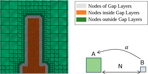
Figure 6. An illustration of the gap node layers.
Based on the above assumptions, the minimum number (N) of gap layers can be expressed by the following Equations 1–3. The process always begins with gap layer 0, which intersects with the building surfaces. In this study, gap layer 0 is not counted in the number of gap layers. The common conditions for gap space definitions are analyzed with the formulas. As the mesh expansion ratio is advised to not be larger than 1.3, two more expansion ratios of 1.1 and 1.2 are used. The minimum number of gap layers is determined by the mesh expansion ratio and the mesh size ratio. The common conditions for the minimum number of gap layers are summarized in Table 1.
where
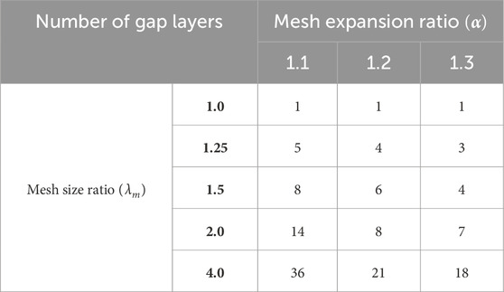
Table 1. Summary of the minimum number of gap layers under common conditions.
(A) is the size of the Cartesian grid. (B) is the grid size of the building surface. (A) should be equal to or larger than (B).
L is the minimum distance when B grows not less than A with
A clear trend can be seen that the number of gap layers increases remarkably with the growth of the mesh size ratio, no matter which mesh expansion ratio is used. This means that the building surface mesh size must be limited according to the Cartesian grid size selection in order to keep the number of gap layers small enough. The analytical result is very instructive on setting up mesh size parameters in the octree-based mesh generation. Keeping the mesh size ratio not larger than 2 is reasonable in order to not introduce many tetrahedrons in the gap.
In the traditional octree structure practice, the node is made of a cube with the same size in length, width, and height, and the number of child nodes in the octree structure is constantly defined as eight. However, under urban-scale wind simulations, the definition of the root node as a cube region for the computational domain does not follow the size of the domain with a 15H distance from the building for the outlet and a 5H distance from the building for the inlet, lateral, and top domain boundaries, as advised in the COST recommendation (Franke, 2006). In addition, splitting the node constantly into eight octants would generate an unnecessarily large number of grids when vertical refinement of grids gradually from the ground surface to the topmost boundary surface of the domain is required for wind profile approximation. Therefore, the octree data structure is modified to incorporate the following features: (1) Introduce length, width, and height variables in the octree node abstraction instead of only the cube size; (2) Provide a method of splitting an octree node horizontally along the Z direction into two child nodes in addition to the traditional eight-child splitting method.
Thus, the modified octree node brings two benefits to the grid arrangement in the domain.
(1) The size of grids becomes flexible in each direction to present an arbitrary cuboid domain.
(2) Vertical refinement only along the Z direction becomes applicable for efficient approximation of the wind profile.
The effect of such modifications is demonstrated with an example shown below in Figure 7.
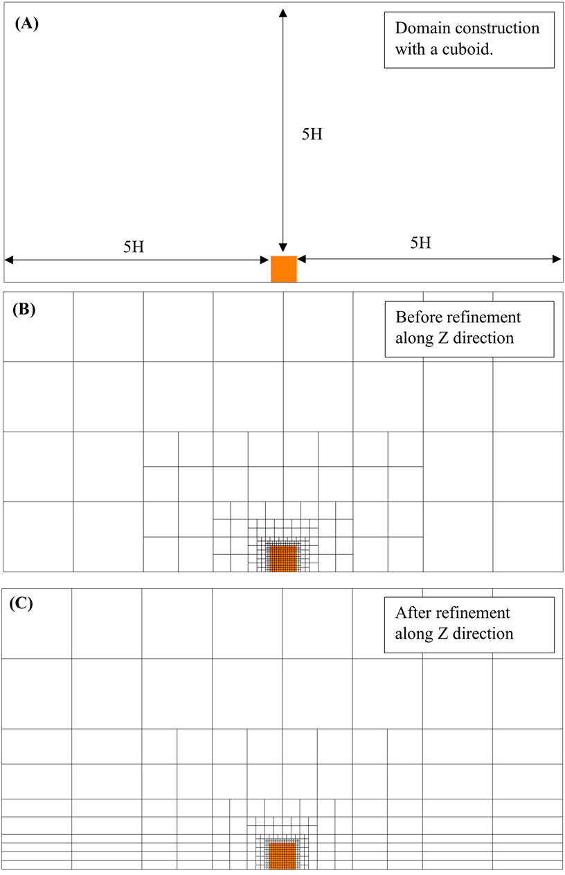
Figure 7. An example of a cuboid domain (A) and its mesh arrangement before vertical refinement (B) and after vertical refinement (C).
The Delauney-based 3D tetrahedralization is adopted to handle the task of generating the tetrahedral grid in the gap. The boundary-constrained Delauney triangulation algorithm in 2D has been well studied. It had been proved that all the edges in the 2D geometry could be represented in a constrained way without any auxiliary points required to formulate a Delauney triangulation (O’Rourke, 1994). However, it is still a problem in 3D boundary-constrained Delauney triangulation (Cavalcanti and Mello, 1999; Shewchuk, 2008). Steiner points must sometimes be added as extra points in the boundary to complete the 3D triangulation process. The position and number of the Steiner points will affect the final mesh quality.
For the present study, the size of the gap between the building surfaces and the gap interface of the Cartesian grids become factors affecting the quality of the final mesh. Another contributing factor is the input surface mesh quality of the building. As the input geometry surface is provided with STL format by the user, the initial input mesh quality is not guaranteed normally. Therefore, remeshing the input geometry surfaces is necessary to obtain a good quality surface triangulation before starting the 3D tetrahedral mesh generation. The techniques for surface triangulation and 3D Delauney triangulation are well developed. Algorithms from open-source libraries are available to be used directly. API functions are vailable in the Computational Geometry Algorithm Library (CGAL, 2023) and TetGen Library (Hang, 2020) for surface mesh reconstruction and 3D triangulation with constrained boundary. The surface remeshing method in CGAL and 3D triangulation in TetGen are used in the current study.
The mesh quality of the Cartesian grid can be guaranteed due to its ideal orthogonality and regular shape. Hence, the mesh quality of this hybrid grid strategy depends on the tetrahedral mesh quality, which is very important to the accuracy of the numerical simulation, and sometimes, it decides whether a simulation can be converged. There is no unique definition of the term “mesh quality,” but good quality mesh normally has a better roundness. The tetrahedron shape measures used in TetGen are the face angles (angles between two edges) and dihedral angles (angles between two faces) as the shape measures of a tetrahedron. They work well with the Delaunay refinement algorithm used in TetGen to avoid badly shaped tetrahedrons like the situations in Figure 8. Based on the authors’ experience, with proper settings on the surface mesh size and space size for the gap layers, Steiner points can be avoided at the boundary and limited in the interior of the gap. Tetgen can produce tetrahedrons with satisfied mesh quality for successful simulation.
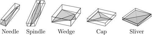
Figure 8. Examples of tetrahedrons with bad mesh quality.
Addressing the conformal connectivity between the Cartesian grid and the tetrahedral grid at the interface of the gap is relevant to the CFD solver. In this study, the OpenFOAM solver (OpenFOAM Foundation Ltd, 2016), which supports an unstructured polyhedron grid system based on the finite volume method (Moukalled et al., 2016), is used. A trick can be used on the Cartesian grids at the interface of the gap without special treatments on the tetrahedral grids. As the facets of a Cartesian grid element are rectangles, the facets at the gap interface can be treated as two triangles by connecting the diagonal line. Thus, the Cartesian grid can be considered an unstructured polyhedron in the OpenFOAM solver. Hence, all the facets of the Cartesian grids at the gap interface can be modified as triangles. During the 3D triangulation, adding the interface triangles together with the building surface triangles as constrained boundary faces would ensure an identical interface for the outer zone and inner zone.
Under some conditions, the grid sizes of the Cartesian grids at the gap interface are not the same; special treatment is required to ensure grid conformity because hanging points are not supported in the OpenFOAM solver. Given a focused node face at the gap interface, several connection templates are summarized. The simplest condition is that if all the neighbors of the face have the same size, the focused face is considered as two triangles. For the other conditions, if one or more of the neighbors is smaller than the focused face, then based on the location of the small neighbor, the focused face can be split into 5–8 triangles, as shown in Figure 9.
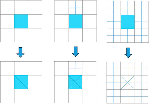
Figure 9. The templates for interface treatment under different connection conditions.
To initialize the hybrid grid generation, the mesh density should be decided in advance as input parameters. The input parameters for mesh density are minimized to reduce the manual effort in the grid generation process. For this hybrid grid generation algorithm, six kinds of parameters can be defined by users, including:
1. Global maximum mesh size (or maximum node level);
2. Mesh size for geometry surfaces;
3. Number of buffer and gap layers;
4. Mesh size for grids in buffer layers;
5. Mesh size for customized refinement box defined by the user;
6. Mesh size for vertical refinement region along the Z direction.
The first four parameters are required inputs to make the algorithm run, while the last two parameters provide flexibility on customized requirements on the mesh density control in the domain. The global maximum mesh size and the mesh size for geometry surfaces are used as the preliminary grid size requirements to initiate the octree-based Cartesian splitting recursively. The number of gap layers can be determined by referring to Table 1, and the number of buffer layers is set by default as four larger than the number of gap layers. Customized local refinement can be realized by defining a virtual box in the domain such that the grid size within the box can be controlled based on user requirements. Finally, gradual vertical refinement along the Z direction can be realized by a list of user input parameters, such as grid sizes under 32 m, 16 m, 8 m, etc., above the ground level. An overview of the proposed hybrid grid generation algorithm is illustrated in Figure 10. The operation procedure involves nine steps:
1. Prepare the building geometry inputs and define the mesh density parameters;
2. Define a root node that covers the whole computational domain;
3. Split the node until the defined mesh density is fulfilled while keeping the octree 2:1 balanced;
4. Identify the nodes that are intersected with building surfaces, inside and outside the building surfaces;
5. Formulate a gap space by definitions of buffer and gap layers;
6. Re-mesh the building surfaces to ensure a good surface mesh quality if necessary;
7. Generate tetrahedral mesh in the gap;
8. Interface treatment for conformal connection;
9. Output the mesh in the OpenFOAM-supported format.

Figure 10. Overview of the algorithm working procedure.
In order to investigate the effectiveness and applicability of the proposed hybrid grid strategy, it is applied to a typical high-rise residential building geometry, consisting of a 45 m × 100 m × 15 m podium and a 108-m-high tower. The result of the hybrid grid arrangement for the high-rise residential building is obtained, as shown in Figure 11. The domain is discretized with Cartesian grids dominating the outer zone far away from the building geometry with gradual local refinements. In addition, the vertical refinement along only the Z direction is implemented with a fine grid size close to the ground surface such that the wind profile can be approximated with good accuracy; meanwhile, the number of grid elements would not significantly increase. It is also noted that the inner zone bounding the building geometry is minimized. Looking into the sectional views, the gap interface follows the building shape so that the Cartesian grids occupy most of the domain, and only the space close to the building surfaces is filled with tetrahedrons.
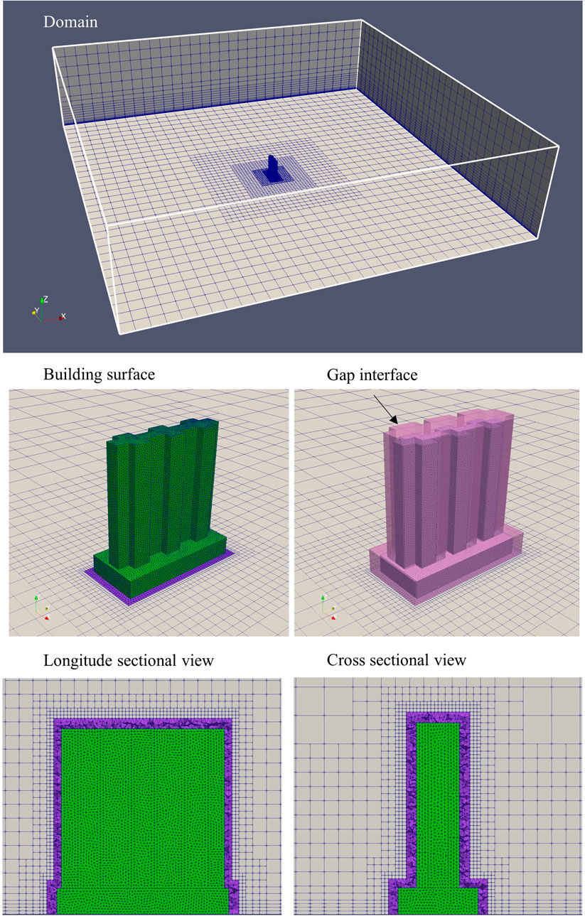
Figure 11. The hybrid grid scheme for a domain with a typical residential building.
The total number of grid elements generated with the hybrid grid arrangement is 281,541. The comparison between the hybrid grid and the all-tetrahedral grid arrangements with the same grid size settings is summarized in Table 2, and the grid breakdown analysis is shown in Figure 12. The number of grids generated under the basic grid settings without any grid refinement is 81,876 for the hybrid grid scheme and 411,331 for the all-tetrahedral grid scheme. There is approximately an 80% reduction for the hybrid grid case compared to the all-tetrahedral grid case. When considering local refinement and vertical refinement settings, the number of grids for the all-tetrahedral grid scheme increased significantly. The reason is that the tetrahedral shape with a large stretching ratio would deteriorate the mesh quality such that a huge number of small tetrahedrons must be generated to maintain the mesh quality. In contrast, the modified Cartesian grids allow a high stretching ratio, resulting in high efficiency in the domain discretization, and the total number of grids is reduced by as much as 98% in this example case. The significant reduction in the grid amount with the proposed hybrid grid strategy can directly result in efficiency enhancement for computation speed. Moreover, the size of data stored for both the grid system and the simulation results is reduced as well. Therefore, this proposed grid generation approach can benefit big data development for urban built environments with efficient data storage and fast database search.
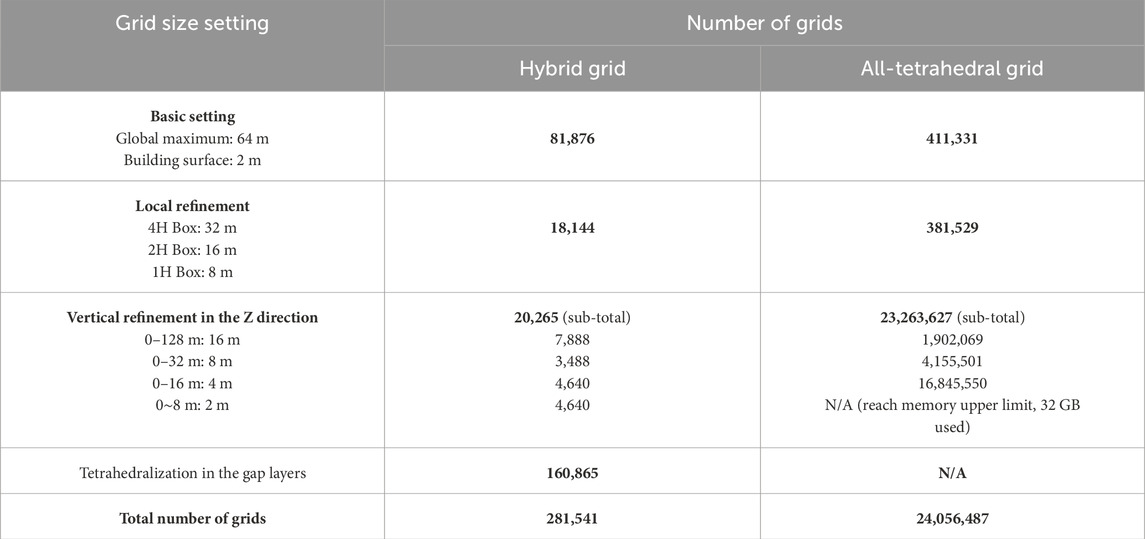
Table 2. Summary of a grid comparison between the hybrid grid and the all-tetrahedral grid arrangements.
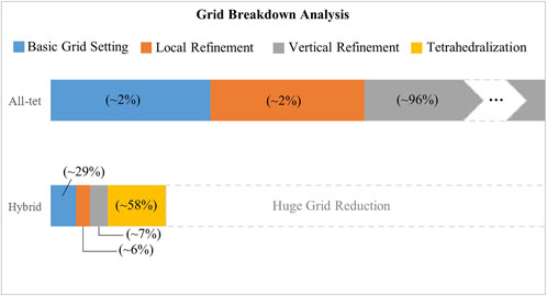
Figure 12. Grid breakdown analysis for the hybrid grid and the all-tetrahedral grid arrangements.
With the successful application of the hybrid grid algorithm on a single building, the target of this study is expanded to an urban-scale model with multiple buildings. The same logic for a single building can apply to multiple buildings, as the octree-based method is designed to discretize the domain automatically to address the manual decomposition limitation for multiple buildings. An example of the hybrid grid generation for a building array is shown in Figure 13.
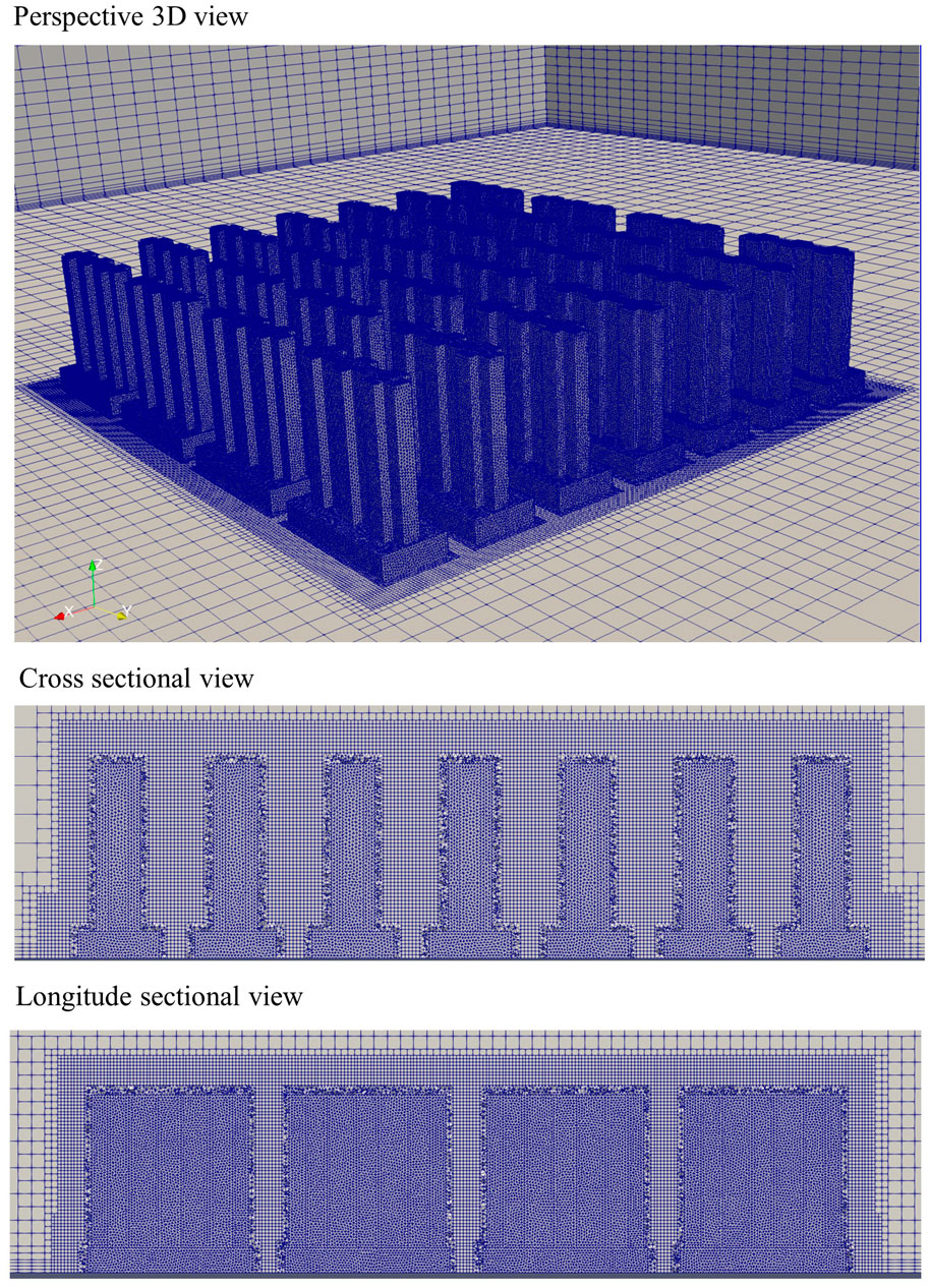
Figure 13. Demonstration of the hybrid grid arrangement for a multiple buildings model.
Wind simulations for a 6-m cube are conducted to validate the simulation results from the proposed hybrid grid generation method with the experimental measurement data. This building cube was constructed at Silsoe Research Institute, Bedford, UK, in an open country exposed position, as shown in Figure 14A. Detailed measurements include surface pressure on the cube and wind velocity in the region around the cube. Richards et al. (2001) published the full-scale field measurement data with a comparison to various wind tunnel tests that provided valuable experimental data for numerical simulation validation.

Figure 14. The building cube photo in real world (A) and the geometrical model for CFD (B).
In the present study, the pressure coefficient data along the vertical and horizontal centerlines of the cube are used to validate the simulation results with different turbulence models. The pressure coefficient is defined as Equation 4
where
The physical model used for numerical simulation is constructed with the same size as the real cube with 6 m. The computational domain is made with reference to the COST recommendation by Franke (2006), with a 15H distance from the building on the front, back, left, and right sides and a 5H distance on the top side. The computational domain and the cube model are shown in Figure 14B.
The inlet boundary is set up based on the wind profile data from the on-site measurements, as shown in Table 3 (Richards et al., 2001), and implemented by Equations 5–8. The log-law velocity profile with specified
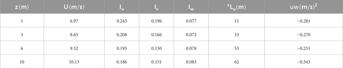
Table 3. Wind profile data from the on-site measurements (Richards et al., 2001).
where
The outlet boundary is set as a relative static pressure of zero and zero normal gradients for the other variables. For ground and cube surfaces, a no-slip rough wall with a roughness height of 0.01 m is set. Symmetry is used for the side and top domain boundaries.
A second-order discretization scheme is used for simulation accuracy, and the residual convergence level is achieved at less than 1e−4 for all variables; meanwhile, the pressure probe points are monitored to ensure the simulation is converged. The simulations are carried out with OpenFOAM CFD solver.
The results of the different Reynolds averaged Navier–Stokes equation (RANS) models are provided in Figure 15. In general, a similar trend in the pressure coefficient distribution on the cube surfaces is generated with the three different turbulent models by CFD simulations compared to the field measurement data. Pressures from the standard

Figure 15. Mean pressure coefficients along the centerlines of the cube.
The proposed hybrid grid approach can be applied to the commonly used turbulence models for urban ventilation simulation. The simulation results are comparable to the full-scale measurements on site. This case study has validated the accuracy of the hybrid grid arrangement on wind flow around a typical building bluff body. Therefore, the proposed hybrid grid generation algorithm provides an alternative flexible, efficient, and automatic domain discretization method for urban ventilation study compared to the traditional tetrahedral grid generation algorithms. Designers, planners, and CFD engineers can employ it as a tool with reduced mesh elements to accelerate the computation time and shorten design turnaround. Finally, the grid system data, together with various numerical simulation results based on the grid system, can be important data sources for the construction of big data for the urban built environment.
In this study, an innovative hybrid grid generation method is proposed for urban ventilation simulation. The example for the single building demonstrated that the hybrid grid arrangement can handle typical building geometry with a Cartesian grid dominating the domain and minimized tetrahedral elements near the building surfaces such that the grid efficiency is improved significantly with a grid element reduction of up to 98% compared to the all-tetrahedral grid scheme. Additionally, this efficient grid generation approach can benefit wind data integration into big data systems for urban built environments. The multiple buildings example showed the applicability to urban-scale ventilation studies.
The validation case study showed that good agreement was obtained on the windward cube surface, and an acceptable pressure coefficient value was obtained on the leeward cube surface compared to the measurement data. The only noticeable discrepancy was observed on the roof surface due to the limitation of the RANS turbulence model, which was also reported in the previous research. Therefore, the accuracy of the proposed hybrid grid method has been proved in the case study.
Overall, this research has contributed a practical grid generation approach for efficient and reliable urban ventilation simulation by an automatic grid generation process. It can shorten the design turnaround time and contribute a critical component to big data in urban built environments for data-driven design processes by providing valuable wind field data with efficient data storage and data processing.
However, this hybrid grid generation algorithm is not perfect, and future work could consider the following:
■ optimize the octree structure to handle more complex topography, such as mountains in the computational domain.
■ improve the algorithm running efficiency to address one hundred million and more octree nodes with a parallel approach.
■ incorporate other tetrahedral grid generation algorithms and boundary layer expansion algorithms.
■ employ other more accurate turbulence models, for example, LES and validate with the experimental data.
The original contributions presented in the study are included in the article/Supplementary Material; further inquiries can be directed to the corresponding authors.
JW: writing–original draft, conceptualization, writing–review & editing, data curation, methodology, visualization, and software. RY: writing–review & editing, funding acquisition, supervision, and project administration. LW: formal analysis, funding acquisition, investigation, and writing–review & editing.
The author(s) declare that financial support was received for the research, authorship, and/or publication of this article. The research work was financially supported by the Research Grants Council of the Hong Kong Special Administrative Region (CRF - Collaborative Research Fund: C7080-21G) and the Guangzhou Science and Technology Plan Project (202201011084).
The authors declare that the research was conducted in the absence of any commercial or financial relationships that could be construed as a potential conflict of interest.
The author(s) declare that no Generative AI was used in the creation of this manuscript.
All claims expressed in this article are solely those of the authors and do not necessarily represent those of their affiliated organizations, or those of the publisher, the editors and the reviewers. Any product that may be evaluated in this article, or claim that may be made by its manufacturer, is not guaranteed or endorsed by the publisher.
Burstedde, C., Wilcox, L. C., and Ghattas, O. (2011). p4est: scalable algorithms for parallel adaptive mesh refinement on forests of octrees. SIAM J. Sci. Comput. 33 (3), 1103–1133. doi:10.1137/100791634
Calvo, N., and Idelsohn, Y. (2000). All-hexahedral element meshing: generation of the dual mesh by recurrent subdivision. Comput. Methods Appl. Mech. Eng. 182 (3-4), 371–378. doi:10.1016/s0045-7825(99)00199-1
Cavalcanti, P. R., and Mello, U. T. (1999). Three-dimensional constrained Delaunay triangulation: a minimalist approach. Int. Meshing Roundtable Conf.
Computational Geometry Algorithm Library (CGAL) (2023). User manual documentation. Available at: https://doc.cgal.org/latest/Manual/packages.html.
Fallahpour, M., Naeini, H. G., and Mirzaei, P. A. (2024). Generic geometrical parametric study of wind-driven natural ventilation to improve indoor air quality and air exchange in offices. J. Build. Eng. 84, 108528. doi:10.1016/j.jobe.2024.108528
Franke, J. (2006). “Recommendations on the use of CFD in predicting pedestrian wind environment,” in In the fourth international symposium of computational wind engineering, Yokohama, Japan, 15 January 2025.
Hang, S. (2010). Constrained Delaunay tetrahedral mesh generation and refinement. Finite Elem. Analysis Des. 46, 33–46. doi:10.1016/j.finel.2009.06.017
Hang, S. (2020). Tetgen - a quality tetrahedral mesh generator and 3D Delaunay triangulator. User’s Man. Version 1.6. Available at: http://www.tetgen.org.
Huang, L. L., Zhao, G. Q., Wang, Z. L., and Zhang, X. W. (2016). Adaptive hexahedral mesh generation and regeneration using an improved grid-based method. Adv. Eng. Softw. 102, 49–70. doi:10.1016/j.advengsoft.2016.09.004
Huang, S., Li, Q. S., and Xu, S. (2007). Numerical evaluation of wind effects on a tall steel building by CFD. J. Constr. Steel Res. 63, 612–627. doi:10.1016/j.jcsr.2006.06.033
Isaac, T., Burstedde, C., and Ghattas, O. (2012). “Low-cost parallel algorithms for 2:1 octree balance,” in IEEE 26th international parallel and distributed processing symposium, USA, 21-25 May 2012.
Ives, D. (1995). “Geometric grid generation. Surface modeling, grid generation, and related issues in computational fluid dynamic (CFD) solutions,” in Proceedings NASA-conference. Cleveland, Ohio, NASA CP-3291, USA March 1, 1995.
Kosicki, M., Tsiliakos, M., ElAshry, K., and Tsigkari, M. (2022). “Big data and cloud computing for the built environment,” in Industry 4.0 for the built environment. Structural Integrity. Editors M. Bolpagni, R. Gavina, and D. Ribeiro (Cham: Springer), 20, 131–155. doi:10.1007/978-3-030-82430-3_6
Launder, B. E., and Spalding, D. B. (1972). Mathematical models of turbulence. London: Academic Press.
Li, Q. S., Fang, J. Q., Jeary, A. P., and Paterson, D. A. (1998). Numerical evaluation of wind loading on buildings by CFD. Hong Kong Institution Eng. Trans. 5 (3), 51–57. doi:10.1080/1023697x.1998.10667763
Liu, Y., Lo, S. H., Guan, Z. Q., and Zhang, H. W. (2014). Boundary recovery for 3D Delaunay triangulation. Finite Elem. Analysis Des. 84, 32–43. doi:10.1016/j.finel.2014.02.006
Lohner, R., and Parikh, P. (1988). Generation of three-dimensional unstructured grids by the advancing -front method. Int. J. Numer. Methods Fluids 8, 1135–1149. doi:10.1002/fld.1650081003
Mitchell, S. A. (1996). “A characterization of the quadrilateral meshes of a surface which admit a compatible hexahedral mesh of the enclosed volume,” in Proceedings STACS’96. Grenoble.
Mochida, A., Tominaga, Y., and Yoshie, R. (2006). AIJ Guideline for Practical Applications of CFD to Wind Environment around Buildings. The fourth international symposium on computational wind engineering. Yokohama.
Moukalled, F., Mangani, L., and Darwish, M. (2016). The finite volume method in computational fluid dynamics - an advanced introduction with OpenFOAM® and Matlab®.
Muller-Hannemann, M. (1999). Hexahedral mesh generation by successive dual cycle elimination. Eng. Comput. 15, 269–279. doi:10.1007/s003660050022
Murakami, S., and Mochida, A. (1988). 3-D numerical simulation of airflow around a cubic model by means of the model. J. Wind Eng. Industrial Aerodynamics 31, 283–303. doi:10.1016/0167-6105(88)90009-8
OpenFOAM Foundation Ltd (2016). OpenFOAM user guide version 4.0. Available at: https://openfoam.org.
Patankar, S. V. (1980). Numerical heat transfer and fluid flow. USA: Hemisphere Publishing Corporation.
Price, M. A., and Armstrong, C. G. (1997). Hexahedral mesh generation by medial Axis subdivision: II. Solids with flat and concave edges. Int. Jou. Num. Meth. Eng. 40, 111–136. doi:10.1002/(sici)1097-0207(19970115)40:1<111::aid-nme56>3.0.co;2-k
Price, M. A., Armstrong, C. G., and Sabin, M. A. (1995). Hexahedral mesh generation by medial surface subdivision: Part I. Solids with convex edges. Int. Jou. Num. Meth. Eng. 38, 3335–3359. doi:10.1002/nme.1620381910
Rassineux, A. (1998). Generation and optimization of tetrahedral meshes by advancing front technique. Int. J. Numer. Methods Eng. 41, 651–674. doi:10.1002/(sici)1097-0207(19980228)41:4<651::aid-nme304>3.0.co;2-p
Razak, A. A., Hagishima, A., Ikegaya, N., and Tanimoto, J. (2013). Analysis of airflow over building arrays for assessment of urban wind environment. Build. Environ. 59, 56–65. doi:10.1016/j.buildenv.2012.08.007
Richards, P. J., Hoxey, R. P., and Shortb, L. J. (2001). Wind pressures on a 6m cube. J. Wind Eng. Industrial Aerodynamics 89, 1553–1564. doi:10.1016/s0167-6105(01)00139-8
Schneiders, R. (1996). A grid-based algorithm for the generation of hexahedral element meshes. Eng. Comput. 12, 168–177. doi:10.1007/bf01198732
Shephard, M., and Georges, M. (1991). Automatic three-dimensional mesh generation by the finite octree technique. Int. J. Numer. Methods Eng. 32, 709–749. doi:10.1002/nme.1620320406
Shewchuk, J. R. (1997). Delauney refinement mesh generation. Pittsburgh: Carnegie Mellon University. PhD Thesis.
Shewchuk, J. R. (2008). General-dimensional constrained Delaunay and constrained regular triangulations, i: combinatorial properties. Discrete Comput. Geometry 39, 580–637. doi:10.1007/s00454-008-9060-3
Smith, C., and Levermore, G. (2008). Designing urban spaces and buildings to improve sustainability and quality of life in a warmer world. Energy Policy 36, 4558–4562. doi:10.1016/j.enpol.2008.09.011
Sundar, H., Sampath, R., and Biros, G. (2008). Bottom-up construction and 2:1 balance refinement of linear octrees in parallel. SIAM J. Sci. Comput. 30 (5), 2675–2708. doi:10.1137/070681727
Taghavi, R. (1994). Automatic, parallel and fault tolerant mesh generation from CAD on Cray research supercomputers. Proc. CUG Conf. Tours, Fr.
Tam, T. K. H., and Armstrong, C. G. (1993). Finite element mesh control by integer programming. Int. J. Numer. Methods Eng. 36, 2581–2605. doi:10.1002/nme.1620361506
Thompson, J. F., Warsi, Z. U. A., and Mastin, C. W. (1985). Numerical grid generation: foundation and applications. North Holland.
Tong, Z. M., Chen, Y. J., and Malkawi, A. (2016). Defining the Influence Region in neighborhood-scale CFD simulations for natural ventilation design. Appl. Energy 182, 625–633. doi:10.1016/j.apenergy.2016.08.098
Versteeg, H. K., and Malalasekera, W. (1995). An introduction to computational fluid dynamics: the finite volume method. New York: Longman Scientific and Technical.
Yang, T. W., Etheridge, N. G., and Quinn, A. D. (2006). A comparison of CFD and full-scale measurements for analysis of natural ventilation. Int. J. Vent. 4, 337–348. doi:10.1080/14733315.2005.11683713
Keywords: urban ventilation, grid generation, hybrid grid, CFD simulation, validation, octree data structure
Citation: Wang JX, Yuen RKK and Wang L (2025) An innovative hybrid grid generation for urban ventilation simulation. Front. Built Environ. 11:1525361. doi: 10.3389/fbuil.2025.1525361
Received: 09 November 2024; Accepted: 13 February 2025;
Published: 08 April 2025.
Edited by:
Chen Ren, Southeast University, ChinaReviewed by:
Yuwei Dai, University of Shanghai for Science and Technology, ChinaCopyright © 2025 Wang, Yuen and Wang. This is an open-access article distributed under the terms of the Creative Commons Attribution License (CC BY). The use, distribution or reproduction in other forums is permitted, provided the original author(s) and the copyright owner(s) are credited and that the original publication in this journal is cited, in accordance with accepted academic practice. No use, distribution or reproduction is permitted which does not comply with these terms.
*Correspondence: John Xin Wang, eHdhbmcyNTItY0BteS5jaXR5dS5lZHUuaGs=; Richard Kwok Kit Yuen, cmljaGFyZC55dWVuQGNpdHl1LmVkdS5oaw==
Disclaimer: All claims expressed in this article are solely those of the authors and do not necessarily represent those of their affiliated organizations, or those of the publisher, the editors and the reviewers. Any product that may be evaluated in this article or claim that may be made by its manufacturer is not guaranteed or endorsed by the publisher.
Research integrity at Frontiers
Learn more about the work of our research integrity team to safeguard the quality of each article we publish.