 Varun Sabu Sam
 N. Anand
 Chady EL Hachem2
 Mirvat Abdallah
 Marc Azab
94% of researchers rate our articles as excellent or good
Learn more about the work of our research integrity team to safeguard the quality of each article we publish.
Find out more
ORIGINAL RESEARCH article
Front. Built Environ., 12 March 2025
Sec. Sustainable Design and Construction
Volume 11 - 2025 | https://doi.org/10.3389/fbuil.2025.1525141
This article is part of the Research TopicCold-formed Steel StructuresView all articles
This paper aims to investigate the flexural behavior of Galvanized Iron (GI) based CFS built-up beams with lipped channels and lipped channel with different stiffener arrangements when exposed to prolonged periods of elevated temperature. Seven built-up beam specimens, each consisting of two lipped channel profiles placed back-to-back, are fastened with self-driving screws in the webs and tested for four point bending experimentally. Following the heating process, two distinct cooling methods were employed to return them to room temperature. The flexural behavior, ultimate moment capacity and moment-deflection curves of tested CFS built-up beams are discussed. Sections cooled using water demonstrate more deformation compared to those cooled using air. Notably, the beam section heated for 90 min and cooled using water showed a deformation of 2.62 mm, representing 1.84 times increase compared to the reference section. Detailed finite element (FE) models were developed and calibrated against the experimental results. They were then employed for a parametric study. Parametric analysis is conducted to study the flexural behavior of two additional types of CFS built-up sections. These include two back-to-back lipped channels with different web stiffeners, in comparison with a basic built-up section consisting of lipped channels. The cross-sectional area of all three sections is identical. The comparison of results reveals that the built-up section consisting of lipped channels with type II web stiffeners have the highest moment-carrying capacity among all profiles for all durations of heating and cooling. Among the unheated sections, the moment capacity of the built-up section with type II web stiffeners is 42.49% and 46.28% higher than that of the reference section and the built-up section with type I web stiffeners, respectively. This study provides practical insights for structural applications, emphasizing the influence of stiffeners and cooling methods on the performance of CFS beams under fire exposure. Additionally, it evaluates the applicability of the Direct Strength Method (DSM) in AISI specifications, offering potential refinements to design codes for CFS built-up sections subjected to elevated temperatures.
Cold formed steel (CFS) has seen its growing utilization across diverse structural applications recently. Availability of different materials and grades of CFS offers a broad spectrum of choices for construction purposes. These grades typically have significant strength and ductility, coupled with corrosion resistance, rendering the advantageous, particularly in challenging environmental conditions. Nonetheless, CFS structures encounter a decline in strength when exposed to fire, a characteristic shared with other steel materials. Investigation of CFS structures under elevated temperatures has gained recent interest among researchers. Finite element (FE) and parametric simulations were employed to analyze behavior of these structures when subjected to heightened temperatures.
Study by Baddoo and Francis (2014) was on developing design rules in AISI design (AISI S100-16, 2016) for structural steel. These investigations assessed the current design methods in structural design specifications, revealing that more comprehensive and less conservative design rules could be incorporated into the design process. Furthermore, studies done by Huang and Young (2018) was focused on structural performance of CFS stainless steel beams in high temperatures and they proposed a modified direct strength method (DSM) which can be used for flexural members at room and elevated temperatures. Influence of thickness on the behavior of CFS sections subjected to axial compression was investigated by Roy et al. (2018). The study proposed enhanced design rules for CFS sections under axial compression based on the findings. These investigations contributed to a better understanding of the structural behavior of CFS. Investigation on flexural behavior of CFS beams using FE modelling was done by Roy et al. (2021). The study concluded that screw spacing had a minimal effect on the flexural capacity of the beams. Further (Wan et al., 2021), conducted a study on the structural behavior and design of CFS under both bending and torsion. The research revealed that the numerical results proposed by the study aligned well with the test results, particularly in terms of ultimate strength and failure modes. Subsequently, these findings were compared with the existing design equations for bending. These studies have made significant contributions to improving the precision of design equations. Experimental investigation on flexural behavior of CFS ferritic stainless steel was done by Karthik and Anbarasu (2021). Ultimate moment values were compared with conventional design moments, revealing a notable agreement between the two. A machine learning model was developed by Dai et al. (2022) to assess the moment capacity of CFS channel beams with edge-stiffened web holes under bending. New design equations derived from the outcomes of parametric study was proposed. Design equations were proposed by Yun et al. (2022) after investigating the structural behavior of both normal and high-strength steels through numerical modelling. Chen et al. (2022) did both experimental and numerical investigations to examine the structural behavior of CFS ferritic sections. The study assessed the impact of web hole size and section slenderness on the structural characteristics. Recently (Jaya kumar et al., 2023) investigated post fire flexural behavior of CFS built up beams. Sabu Sam et al. (2023) studied about influence of high temperature on buckling capacity of CFS. These investigations indicate that, duration of heating and type of cooling exert a significant influence on reducing the load-carrying capacity of CFS sections. Meanwhile (Prabowo et al., 2023), did extensive research on CFS beams with single web hole at elevated temperature. Whereas (Shakarami et al., 2023) conducted an extensive numerical study to investigate the behavior of bolted connectors in CFS composite beams. The investigation thoroughly examined the effects of bolted shear connectors on ultimate strength, ductility, and failure modes. These studies have played a crucial role in emphasizing the importance and value of performing parametric analysis and numerical studies.
Sabu Sam et al. (2024a) conducted a numerical study on the flexural behavior of unsymmetrical GI based CFS sections with different profiles and concluded that Zed profiles outperform other sections under fire scenarios. This research is significant as it highlights the impact of cross-sectional geometry on structural performance during elevated temperatures, providing a comparative basis for analyzing the performance of lipped and stiffened profiles used in this study. Sam et al. (2024a) investigated the flexural behavior of GI-based CFS beams with varying spans under elevated temperatures. The study also examined the influence of different cooling methods on beam performance. These findings offer valuable insights into the effect of span and cooling scenarios, directly complementing the thermal exposure and cooling methods analyzed in this research. Sam et al. (2024b) explored the flexural behavior of GI-based CFS beams exposed to fire, focusing on various stiffener configurations. Their parametric analysis revealed that beams with vertical stiffeners outperformed those with horizontal stiffeners. This study informed the selection of vertical stiffeners and guided the design of type I and type II stiffener configurations used in the present work. Niemiro-Maźniak and Lacki (2024) conducted experimental and numerical analyses on joints and thin-walled steel beams fabricated through resistance spot welding and hot-dip galvanization. Their findings revealed that GI beams exhibit higher bending load capacity compared to non-GI beams. This research validates the benefits of using GI in CFS construction and emphasizes the importance of material selection, which is a core aspect of the current study.
Literature addressing GI-based CFS beams under elevated temperatures and the impact of different profiles on their flexural behavior is limited. Conducting laboratory experiments under higher thermal exposure is expensive, time-consuming, and poses risks. To address this gap, this study provides a comprehensive experimental and numerical investigation of GI-based CFS built-up beams exposed to prolonged elevated temperatures, followed by two distinct cooling methods (air and water). The inclusion of lipped channels with different web stiffeners under various thermal conditions enables a thorough understanding of the influence of stiffener geometry and heating duration on post-fire performance. The study’s details and outcomes may prove valuable for design databases. After a meticulous review of available literature, this study outlines the following objectives: Experimental and analytical investigations have been carried out to evaluate the flexural behavior of Galvanized Iron (GI) based CFS built-up beams. The study also examines the sections with lipped channels and lipped channel with different stiffener arrangements when exposed to prolonged periods of elevated temperature. These results are subsequently compared with experimental findings and Direct Strength Method (DSM).
The study’s unique contributions include:
Experimental validation of flexural behavior under fire exposure scenarios, representing realistic durations and cooling conditions.
Parametric evaluation of stiffener arrangements, identifying configurations that enhance moment-carrying capacity.
Critical assessment of the applicability of DSM for post-fire conditions, offering insights for potential refinements in design codes.
These findings fill a significant gap in the understanding of post-fire behavior in CFS built-up beams, providing valuable data for design databases and contributing to the development of fire-resilient structural solutions.
This study utilized GI based CFS C sections connected back-to-back for experiment, specifically with a nominal grade of 350, having a length of 1.5 m and nominal thickness of 2 mm. The dimensions of C channel used is shown in Figure 1A. C sections were connected back-to-back using self-tapping screws as shown in Figure 2B, with dimensions provided in Figure 2A. Connections were established using 6 mm diameter screws. For parametric study, CFS built up beams made of GI with different web stiffeners (type 1 and type II) are considered. The dimensions of these built-up beams are given in Figures 1B, C. Vertical stiffeners with a thickness of 2 mm were welded to the beams at both supports and two loading points as seen in Figure 2A. Addition of stiffeners at supports and loading points were provided to prevent twisting during testing. Sections were subjected to heating at desired temperatures and subsequently cooled either using air or water.

Figure 1. Typical cross section of built-up beam sections with (A) reference, (B) type I and (C) type II web stiffeners.
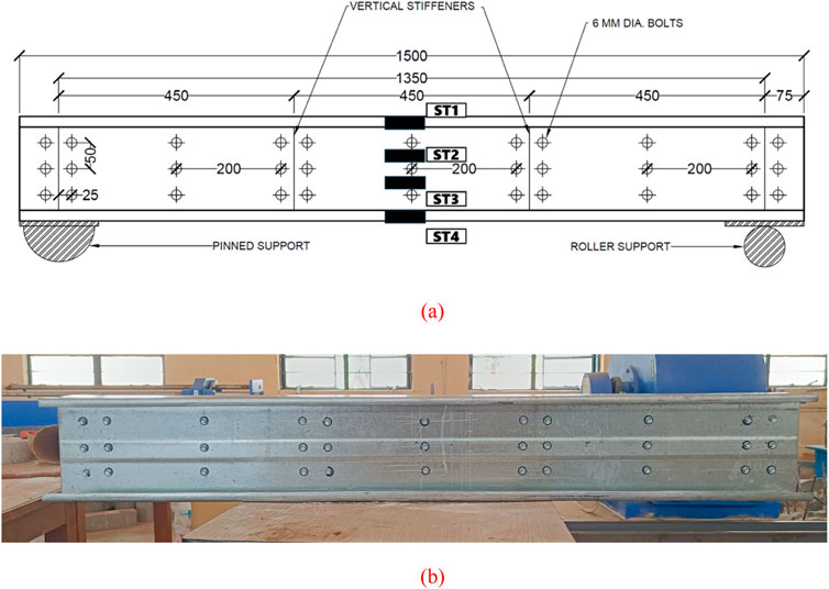
Figure 2. (A) Arrangement of self-tapping screws in beam section. Note – ST1, ST2, ST3, ST4 are the locations at which strain gauge was connected, (B) Reference built up beam connected using self-tapping screws.
Lipped channels with type I and II stiffeners were utilized to do parametric study in this paper. The choice of stiffeners (type I and type II) was driven by their practical relevance and structural performance under elevated temperature conditions. Type I stiffeners were selected as they represent a conventional stiffener design commonly used in CFS structures. This design provides basic enhancement to web stability and is widely adopted in standard structural applications. The inclusion of type I stiffeners allowed to establish a baseline for evaluating the flexural performance of built-up beams, offering a reference for comparison with more advanced stiffener designs.
Type II stiffeners feature a more optimized geometric configuration, designed to enhance distortional buckling (DB) resistance, and improve the moment-carrying capacity of CFS beams. This stiffener type is particularly suited for applications requiring superior performance under demanding loading or thermal conditions. Their inclusion in the study enabled an assessment of the potential benefits of using advanced stiffener designs in built-up sections exposed to prolonged heating and cooling cycles.
The selection of these two stiffener types allowed for a systematic evaluation of their influence on the flexural behavior of built-up beams under elevated temperatures and different cooling conditions. By comparing the results, the study provides insights into the advantages of advanced stiffener configurations (type II) over traditional designs (type I and reference type) in terms of moment-carrying capacity and post-fire performance. This approach ensures the findings are both relevant to current engineering practice and valuable for exploring improved design solutions for fire-resilient structures.
Several measures were taken to minimize and manage variability in the key materials used, including self-tapping screws and GI sheets.
All self-tapping screws were procured from the same manufacturer and batch to ensure uniformity in material composition and mechanical properties. The screws were subjected to random sampling for tensile strength testing, verifying that their properties met the manufacturer’s specifications. Any screws falling outside the acceptable range were discarded.
The GI sheets used for fabricating the CFS lipped channels were sourced from the same supplier and were manufactured in a single production run. This minimized variations in sheet thickness, coating weight, and yield strength. Material certification was obtained from the supplier, detailing the chemical composition, coating thickness, and mechanical properties. Random coupon tests were conducted to verify the reported mechanical properties of the GI sheets, ensuring consistency with the supplier’s data.
To ensure consistent assembly, all specimens were fabricated using the same cutting, forming, and fastening techniques. Proper quality control measures were implemented during assembly to ensure uniform placement and alignment of self-tapping screws and channel profiles.
Geometric imperfections, which are inherent in CFS sections, were measured prior to testing. These included initial out-of-plane deformations and deviations in cross-sectional geometry. The imperfections were within acceptable limits as per design standards, ensuring they did not significantly impact the experimental results. Additional measures, such as uniform handling and storage of specimens, were implemented to prevent the introduction of unintended imperfections during fabrication or testing.
During the experimental phase, any anomalies in behavior or results were cross-checked to determine if material variability was a contributing factor. Consistent results across specimens confirmed the adequacy of our measures to manage variability. By controlling the sources of variability and validating material properties through testing and certification, we have ensured that the experimental results reliably reflect the intended behavior of the GI-based CFS beams.
First, the sheet is formed to the desired shape via the cold roll forming process and then joined together into a back-to-back built-up section using self-tapping screws (Sam et al., 2024a). Any geometric imperfections resulting from these process could affect the buckling behavior and other failure modes of the CFS section. These initial imperfections are quantified for all test specimens. Measurements were taken at six regions along the longitudinal direction of the flange and web of the section. The test specimens are firmly secured on a flat, leveled surface with one end clamped. A digital dial gauge is employed to measure readings at 50 mm intervals along the specimen’s length. The locations at which measurements were taken at the cross-section of the C-section specimens are depicted in Figure 3A. Additionally, Figure 3B illustrates the initial imperfections measured at all points for a test specimen throughout its length. Table 1 shows the measured geometrical imperfections of the section.
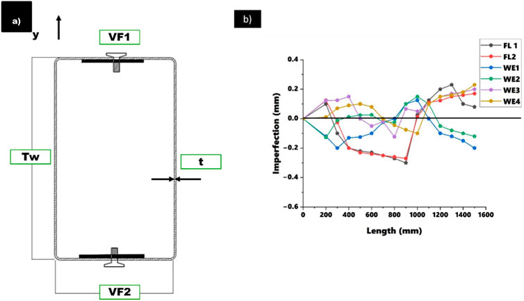
Figure 3. (A) Locations of measurement points, (B) Imperfections measured for the test specimen throughout its length.
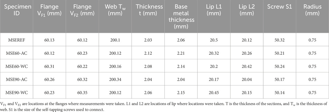
Table 1. Measured dimensions.
Geometric imperfections play a critical role in accurately predicting the structural behavior of CFS beams, particularly under elevated temperatures where buckling phenomena are more pronounced. In this study, the incorporation of geometric imperfections into the FE model followed a systematic approach.
The magnitude and distribution of initial geometric imperfections were quantified based on:
• Experimental Measurements: Imperfections in the tested specimens were measured using precision instruments such as dial gauges. These measurements captured deviations in the web, flange, and lip geometries from their ideal configurations.
• Standards and Guidelines: Where direct measurements were unavailable or impractical, imperfection magnitudes were based on recommendations from design standards, such as AISI S100 (AISI S100-16, 2016) or EN 1993-1-5, which specify permissible initial imperfections for thin-walled steel sections.
In the FE model, imperfections were introduced as scaled versions of the critical buckling mode shapes, which were determined from a linear buckling analysis. This approach reflects real-world imperfection patterns, where the geometry often aligns with the dominant buckling mode. Key details include:
• Shape: The imperfections corresponded to distortional buckling (DB) and lateral-torsional buckling (LTB), as these were the primary failure modes observed in experiments.
• Magnitude: The imperfection magnitude was set as a fraction of the section thickness, typically ranging between t/1000 and t/200, consistent with recommendations in literature and design standards.
The quantified imperfections were incorporated into the FE model using the following steps:
• Mesh Deformation: The FE mesh was adjusted to reflect the imperfection shape and magnitude.
• Imperfection Scaling: The imperfections were scaled appropriately to simulate realistic conditions without introducing overly conservative assumptions.
• Validation: The imperfection parameters were validated by comparing the numerical results to experimental outcomes, ensuring that the chosen values accurately replicated the observed behaviors.
Inclusion of geometric imperfections significantly impacted the load-deflection response, ultimate moment capacity, and failure modes predicted by the FE model:
• Buckling Behavior: The imperfections enhanced the accuracy of predictions for distortional and LTB.
• Load Capacity: Slight reductions in predicted load capacity were observed, consistent with experimental results, as imperfections typically lower the structural resistance of CFS sections.
• Deformation Patterns: The inclusion of imperfections improved the correlation between predicted and observed deformation patterns under both ambient and elevated temperature conditions.
The use of measured imperfections, coupled with standard-based assumptions, ensured that the FE model captured the real-world variability in CFS sections. This methodology enhances the reliability of the findings, making them applicable to practical structural design scenarios.
Electric furnace based on (ISO 834-1, 1999) which is depicted in Figure 4A, was employed to heat the beams for durations of 30, 60 and 90 min (Sabu Sam et al., 2024a; Sabu Sam et al., 2024b; Sabu Sam, 2022). Figure 4B shows the ISO fire curve and the temperature measured on the surface of the section using a temperature gun. Pinned and roller supports were incorporated at both ends as support conditions.
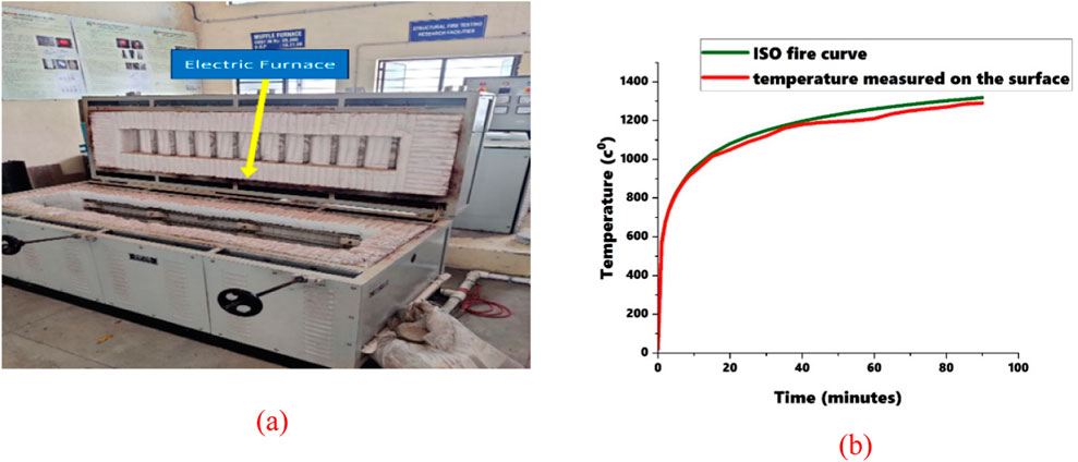
Figure 4. (A) Electric furnace, (B) Comparison of ISO fire curve and sections surface temperature.
The selection of 30, 60, and 90-minute heating durations is based on the time-temperature relationship defined in the ISO 834 fire curve (ISO 834-1, 1999), which is widely adopted in structural fire testing. These durations simulate varying levels of fire exposure, ranging from moderate (30 min) to severe (90 min), representing realistic scenarios in structural fire events. In real-life building fires, the duration of exposure to elevated temperatures can vary depending on factors such as fire load, ventilation, and fire-fighting interventions. For instance, Eurocode EN 1991-1-2 (EN 1991-1-2, 2002) and similar guidelines consider fire durations of 30–120 min as typical benchmarks for fire-resistance ratings. Specifically, 30 min corresponds to short-duration fires, often seen in smaller compartments or with early fire suppression, while 60–90 min align with scenarios in larger compartments or uncontrolled fires.
30 Minutes: This duration reflects short-duration fires typically observed in residential buildings where rapid evacuation is feasible, and fire suppression systems activate quickly.
60 Minutes: Represents a moderate-duration fire scenario, often seen in commercial or mixed-use buildings where evacuation takes longer, and the fire load is higher.
90 Minutes: Simulates extended-duration fires, such as those in industrial settings or buildings with high fire loads, where suppression efforts may face delays, or the fire load sustains combustion for an extended period.
Evaluating beams at these durations provides insights into their behavior under varying levels of thermal exposure. This is essential for determining the residual load-carrying capacity and deformation trends, which directly influence post-fire structural safety and repair decisions.
Heating durations influence the thermal stress and residual effects during cooling. For example, beams exposed to 90 min of heating are subjected to greater thermal gradients, potentially leading to significant metallurgical changes and structural deformations. These effects are critical for understanding the post-fire performance of GI-based CFS beams under different cooling methods (air and water). By selecting these durations, this study aimed to investigate the behavior of CFS built-up beams under a range of fire exposures, allowing the findings to be applicable to practical fire design scenarios. This approach ensures the results are relevant for evaluating the performance of CFS sections under real-world fire conditions and contribute to fire-resistance assessments of structural elements.
The electric furnace used in this study was calibrated according to industry-standard protocols to maintain consistent temperature distribution and reliable heating rates throughout the experiments. The following measures were undertaken:
1. Temperature Monitoring:
• Multiple thermocouples were installed at strategic locations inside the furnace to measure and monitor temperature variations. These thermocouples were connected to a data acquisition system to record real-time temperature data.
• The recorded data was analyzed to confirm uniform temperature distribution across the furnace chamber, ensuring the specimens experienced consistent thermal exposure.
2. Standardized Heating Curve:
• The heating process was governed by the ISO 834 fire curve (ISO 834-1, 1999), ensuring that the furnace temperature followed the prescribed time-temperature relationship. Periodic verification of the furnace’s adherence to this curve was performed using calibrated instruments.
3. Reproducibility Checks:
• Before commencing the experimental program, trial runs were conducted using steel samples to confirm that the furnace could reliably reproduce the desired temperature profiles over different durations (30, 60, and 90 min).
• The trial results were compared against reference standards to validate consistency.
4. Calibration Frequency:
• The furnace was recalibrated periodically during the testing phase to account for any drift in temperature control. This included verifying the accuracy of thermocouples and recalibrating them against a reference standard.
• Additionally, the control panel was calibrated to ensure accurate readings of the set temperature and applied temperature. This involved confirming the alignment of the set temperature with the actual applied temperature using a thermal gun for verification.
• An applied temperature/coil temperature curve was developed and maintained, with the temperature deviations limited to ±5°C to ensure consistent thermal performance throughout the testing.
These measures ensured that the heating process was reproducible and aligned with standard fire testing procedures, providing confidence in the reliability of the experimental results.
After heating and cooling, the beams were tested on Universal Testing Machine (UTM) for four-point bending loading conditions. Four-point loading was applied to simulate the flexural behavior. Deflectometers were positioned beneath bottom flange of the section at both loading points and the midpoint of the beam. Linearly variable differential transducers (LVDTs) were affixed to the side of the web of the beam. The experimental setup is depicted in Figure 5A. Figure 5B shows a specimen undergoing the cooling process after heating, using water.
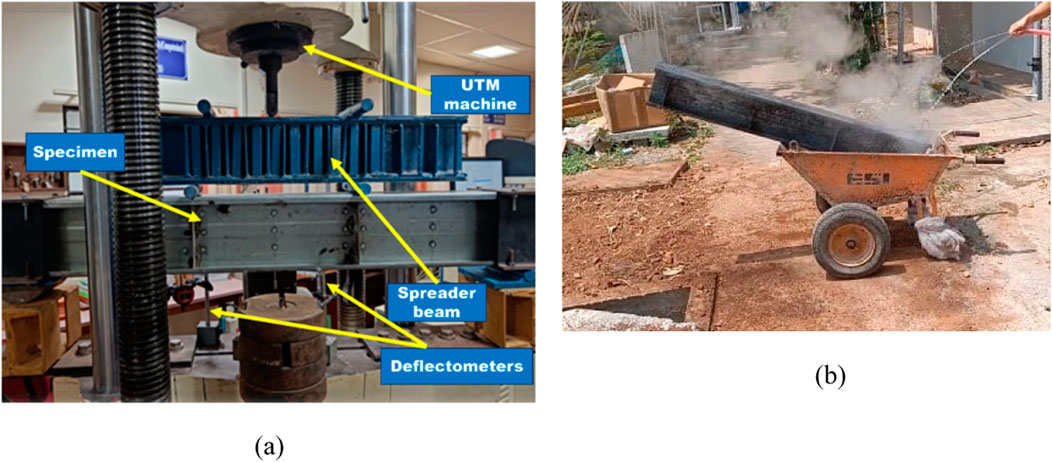
Figure 5. (A) Experimental setup, (B) Beam section cooled down by water.
Specimen IDs are given to sections to identify easily. Sections with reference web stiffener are denoted as “E.60-A.C” where 60 denotes duration of heating and AC denotes method of cooling which in this case is cooled using air. Sections with type I stiffener is denoted by CA.60-A.C and S.60-A.C for type II stiffener.
Strain gauges were strategically positioned on the web and flanges of the CFS built-up beams to capture compressive and tensile strains. The specific locations include:
• ST1 and ST2: Positioned on the compression zone of the web.
• ST3 and ST4: Located on the tension zone of the flange.
Figure 6 depicts the locations of these strain gauges connected on the section. This ensures a comprehensive understanding of strain distribution across the sections.
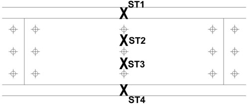
Figure 6. Locations on the beam at which strain gauges were attached.
For parametric analysis, material properties required to stimulate cooling and heating of beam sections were taken from coupon testing results. The specimens were fabricated from the same slot of the material as reported in (Sabu Sam et al., 2024c), therefore same properties are shown in Table 2.
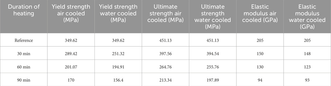
Table 2. Material properties from coupon test.
The beams in this study were simply supported with a fixed length of 1.5 m. This specific beam span was chosen to balance practical considerations (such as limitations with the electric furnace used for heating) with the objectives of the study. However, it is important to note that the behavior of CFS beams under fire exposure may vary with different beam lengths. For example, longer beams are more susceptible to LTB, which could influence both the deformation patterns and moment capacity. Conversely, shorter beams may exhibit different failure modes due to the more significant role of local buckling. Therefore, the results of this study are directly applicable to beams with similar span-to-depth ratios, but additional testing would be needed to evaluate the flexural behavior of CFS beams with longer spans or shorter spans, and how these factors interact with fire exposure.
In this study, the CFS beams were subjected to four-point bending under simply supported conditions, which ensures a well-defined loading configuration and facilitates comparison of results. However, the loading conditions in real-world scenarios can vary significantly. For example, beams in buildings may experience distributed loads or point loads at different locations, which could affect the stress distribution and failure modes under fire conditions. Furthermore, the shear spans and bending moments may vary in real applications, which could lead to differences in the deformation behavior and load-carrying capacity of the beams compared to those tested in this study.
While the study focused on GI and the impact of different stiffeners, the material properties, such as the yield strength and thermal expansion coefficient, can vary across different batches or suppliers of materials. Self-tapping screws used for joining the CFS sections may also exhibit variability in their mechanical properties, potentially affecting the load transfer mechanism between the beams. The experimental approach of this study aimed to minimize this variability by sourcing consistent materials and calibrating the test setup. However, in real-world applications, the potential for material variability could influence the performance of CFS beams under fire conditions.
Experimental tests were conducted on laboratory-scale specimens of GI-based CFS beams. While these provide valuable insights, the results may not fully capture the complexities of real-scale structural elements used in construction. Scale effects, such as the influence of member length, cross-sectional dimensions, and practical constraints like joint and connection behavior, might differ in full-scale applications.
Boundary Conditions: Simplified boundary conditions, such as idealized pinned or roller supports, were assumed in the FEA. These may not precisely represent the conditions experienced in actual structures, potentially affecting the accuracy of predicted results.
Material Properties: Uniform material properties were assumed throughout the specimens, neglecting potential variations or degradation due to manufacturing processes or thermal exposure.
Geometric Imperfections: Although initial geometric imperfections were incorporated based on standard recommendations, their magnitude and distribution might not represent the true imperfections in real-world beams.
Thermal Gradients: The FEA assumed uniform thermal exposure, which may oversimplify the actual temperature distribution experienced during fire scenarios.
Loading Conditions: The study focused on static loading conditions under two-point loading. Dynamic or cyclic loading scenarios, which are critical in seismic or fatigue-prone environments, were not addressed.
Cooling Methodology: Cooling was limited to air and water methods, which may not encompass all real-world cooling conditions, such as those involving insulation or fire suppression systems.
Generalizability to Other Profiles and Materials: The findings are specific to GI-based CFS beams with the studied profiles and stiffener configurations. They may not be directly applicable to other materials, such as stainless steel, or to profiles with significantly different geometries.
Prior to heating, beam sections exhibited a uniformly light glossy grey color, as depicted in Figure 2B. Following the heating process, visible flaking appeared on the surface, as shown in Figures 7A–C. At lower temperatures, color shifted to a greenish-olive shade, as seen in Figure 8B. With further temperature increases, the color transformed into a dark blue shade. There was noticeable brown dust present on the surface across all specimens.

Figure 7. Physical changes observed for (A) Beam sections right after heating, (B) Beam sections after cooling down, (C) Beam section after heating.
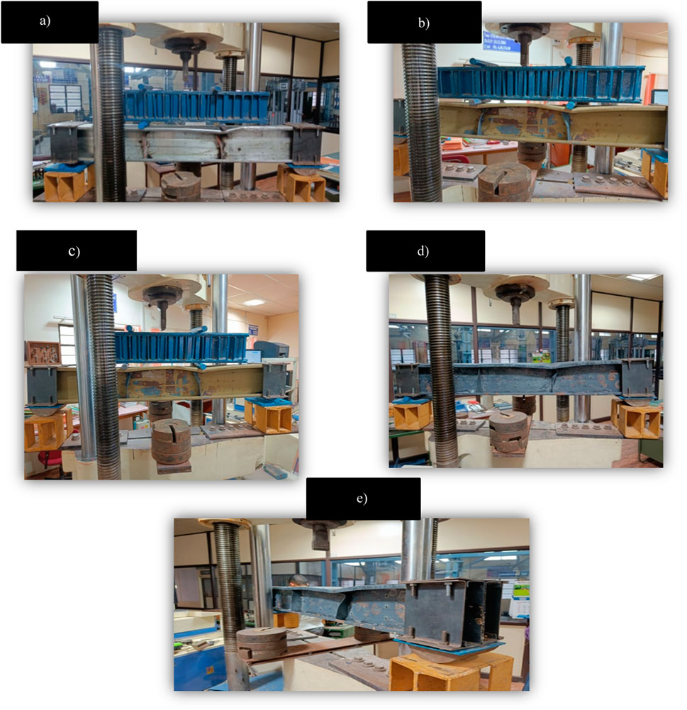
Figure 8. Failure modes of (A) MSEREF, (B) MSE60-AC, (C) MSE60-WC, (D) MSE90-AC, (E) MSE90-WC.
Specimens exhibited DB and local buckling throughout post-load testing. Local buckling occurred notably on the stiffeners positioned beneath the loading points as illustrated in Figure 8. DB occurred in the middle region of the beams, indicating compression failure at the top flange. The provision of additional stiffeners on bearings and the restrained supports effectively prevented LTB.
Ultimate moment is a critical factor in cross-sectional design, establishing safety factors in strength, and is fundamental parameter in determining the stability of structural elements. Figure 9 depicts moment deflection values obtained for all beam sections under elevated temperature tested experimentally. X-axis contained deflection values in mm and Y-axis contains moment values in kNm. In Figure 9, specimen IDs are given for each section like 30 A.C, 30 W.C. Where 30 is duration of heating in minutes and A.C or W.C denotes method of cooling using air or water. The maximum moments obtained for various beam sections ranged between 16.04 kNm and 6.36 kNm, 16.04 kNm being the moment obtained for the reference specimen. Percentage loss of strength is noted to increase with an extended duration of heating. The maximum moment in the sections gradually decreases as the duration of heating is increased (Sam et al., 2024b). Notably, among sections heated for the same duration, those cooled down using water exhibit a lower moment capacity. Sam et al. (2024a) noted that cooling methods significantly impact the structural performance of GI-based CFS beams, with rapid cooling by water inducing greater thermal stresses. Results from this study corroborate this, showing that water-cooled specimens exhibited higher deformations and reduced stiffness compared to air-cooled counterparts due to accelerated thermal gradients and residual stresses. A major decline in moment was noted from 60 min of duration. For 60 min of heating and cooling down using air, a loss of 34.77% was noted in comparison with unheated section. For the section cooled down using water, loss calculated was 43.51%. For 90 min of heating, strength loss noted for sections which were cooled down by air and water was 47.56% and 60.33% respectively. It is quite clear that as the duration of heating was increased, its load carrying capacity also decreased parallelly. This graph provides insights into the structural performance of CFS beam sections and can reveal onset of buckling and help assess the beam’s stability under various temperature and cooling conditions.
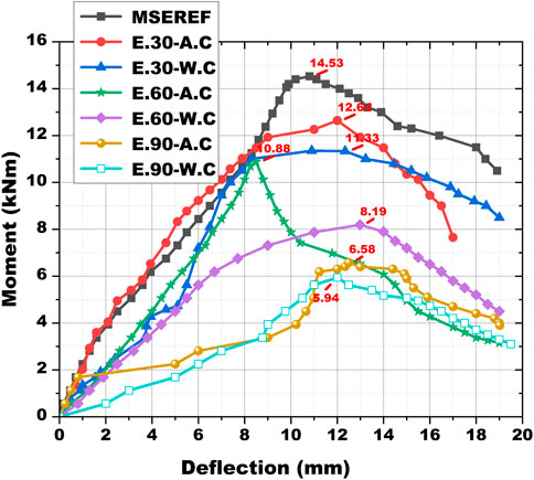
Figure 9. Moment deflection graph obtained for all sections.
The moment-deflection curves not only highlight the ultimate moment capacity but also reveal important details about the onset of buckling.
The curves initially exhibit a linear response, representing the elastic behavior of the material where deflections are proportional to the applied moment. As the moment increases, the curves deviate from linearity, indicating the onset of plastic deformation. This transition is typically associated with the initiation of local or DB, particularly for sections subjected to higher temperatures or cooled using water. The moment-deflection curves for sections heated for 60 and 90 min exhibit a steeper drop after reaching the peak moment, suggesting an earlier onset of buckling compared to the reference specimen. For water-cooled sections, the curves show a more pronounced reduction in stiffness post-buckling, indicating the detrimental impact of rapid cooling on stability. Among all specimens, the reference section demonstrates the highest peak moment and a gradual decline after buckling, indicative of better post-buckling behavior. In contrast, sections exposed to prolonged heating (90 min) and water cooling display sudden drops in the curves, highlighting their reduced capacity to sustain loads after buckling initiation. The earlier onset of buckling in heated and water-cooled sections emphasizes the need for careful consideration of thermal exposure and cooling strategies in structural design. These observations underline the importance of incorporating fire-resilient measures and post-fire evaluations for structures employing GI-based CFS beams.
Stiffness is a fundamental property that characterizes the behavior of a material under an applied load. It is calculated from the load and deflection values of all the beam specimens tested after exposure to elevated temperatures, as illustrated in Figure 10. Stiffness values are given in kN/mm in X-axis and specimen IDs are given in Y-axis. The maximum stiffness is observed in the reference specimen, while the least stiffness is observed in the beam specimen heated for 90 min and cooled down using water (Sam et al., 2024c). Stiffness gradually decreases as the duration of heating is increased. The graph indicates a substantial drop in stiffness from the reference specimen to the heated specimen. There is a difference in stiffness of 29.13% between section which is heated for 60 min and cooled using air and reference section. For the same section, which is cooled using water, the noted difference is 70.51%. Between 30 min of heating and cooling down using water and 60 min of heating and cooling using air, only a minor difference in stiffness is noticed.
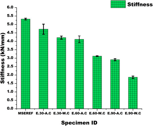
Figure 10. Stiffness calculated for all beam sections.
The observed reductions in stiffness across different specimens can be attributed to the combined effects of elevated temperature exposure and the cooling methods employed.
Elevated temperatures lead to significant changes in the mechanical properties of GI and CFS. Prolonged exposure weakens the material’s yield strength and modulus of elasticity due to phase transformations and grain coarsening, which adversely affect stiffness. The greater the heating duration, the more pronounced the material degradation, as evidenced by the substantial drop in stiffness for specimens subjected to 90 min of heating.
Air Cooling: Gradual cooling allows for a slower reduction in temperature, which minimizes thermal stresses and microstructural distortions. Consequently, sections cooled using air retain relatively higher stiffness compared to those cooled using water.
Water Cooling: Rapid cooling induces thermal shock, resulting in the development of residual stresses and potentially micro cracks within the material. These factors significantly reduce stiffness, as seen in the 70.51% difference in stiffness for the specimen heated for 60 min and water-cooled compared to the reference section.
The minor difference in stiffness between the 30-minute water-cooled specimen and the 60-minute air-cooled specimen highlights the balancing effects of moderate thermal exposure and slower cooling. This suggests that the cooling method plays a more critical role in stiffness reduction than heating duration alone when the exposure period is limited.
These findings underscore the importance of considering both heating duration and cooling method in assessing post-fire structural integrity. Rapid cooling through water may expedite the process but could lead to greater material damage, while air cooling, though slower, offers a less detrimental alternative for retaining stiffness.
Figure 11 illustrates the lateral deformations observed in all beam sections during the load test. Measurements of lateral deformations, taken near the supports and in the middle portion using digital deflectometers, with a range between 0.92 and 2.62 mm. These deformations exhibit an increasing trend for specimens subjected to longer durations of heating (Sam et al., 2024d). Sections cooled down using water demonstrate more deformation compared to those cooled using air. Notably, the beam section heated for 90 min and cooled down using water showed a deformation of 2.62 mm, representing a 184.78% increase compared to the reference section. When a structure is cooled rapidly, such as in water cooling, a significant thermal gradient is created between the surface and the core of the material. This rapid cooling rate leads to uneven contraction of the material, especially in the case of CFS beams. The outer layers, cooling more quickly, contract faster than the inner sections, which can induce residual stresses. These residual stresses are concentrated at the surface and lead to plastic deformation. In the case of water cooling, the rapid cooling exacerbates this effect, creating high levels of thermal stress. This results in larger strains, particularly in the tension zones of the beam, as the material resists rapid shrinkage. Air cooling, being slower, allows a more uniform temperature distribution and results in lower residual stresses, causing less deformation compared to the rapid cooling seen in water-cooled sections. CFS is susceptible to changes in its microstructure when subjected to elevated temperatures. The rate of cooling can affect these transformations significantly. During water cooling, the high cooling rate can cause quenching effects, where the material undergoes a transformation from austenite to martensite, especially in carbon steels. Martensitic microstructures are more brittle and less ductile, which can cause the material to exhibit higher susceptibility to brittle fracture or plastic deformation. In contrast, air cooling allows for more gradual phase transformations. This reduces the likelihood of forming brittle microstructures like martensite and instead promotes the formation of more ductile phases such as ferrite or pearlite. As a result, the beam section cooled by air tends to exhibit more elastic behavior and less permanent deformation than the water-cooled sections.
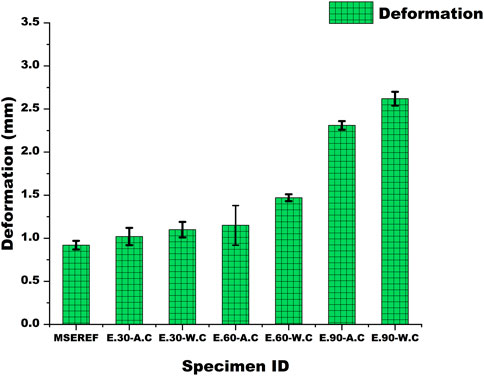
Figure 11. Lateral deformation noted for all beam sections.
Furthermore, for sections heated for 60 min, a variation of 27.83% in deformations is observed between sections cooled using air and water. In the case of 90 min of heating, the difference in deformations between air-cooled and water-cooled sections was noted to be 13.42%. Elevated temperatures have the potential to reduce structural stability of CFS beams, increasing their vulnerability to induce buckling or DB. DB encompasses lateral distortions alongside axial deformations. Reduced stiffness and strength experienced at higher temperatures can result in lateral deformations when subjected to applied loads.
Material’s capacity to deform plastically before reaching failure is known as the ductility factor. The ductility ratio, representing the ratio of displacement at a specified strength or deformation level to the displacement at the yield point, is a common measure of ductility. Materials with high ductility can undergo significant plastic deformation before eventual failure. Figure 12 illustrates the ductility factor obtained for all beam sections exposed to various durations of heating. As the duration of heating increases, the ductility factor also increases. The lowest ductility factor is observed for the reference beam section, while the highest is observed for the beam section heated for 90 min and cooled down using water. There is a notable difference of 34.34% between the reference section and the section heated for 90 min and cooled down using water.
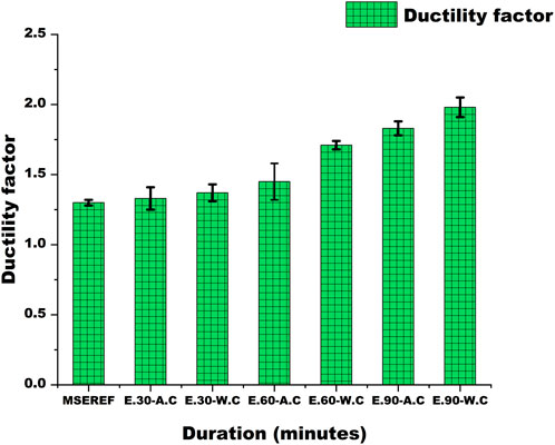
Figure 12. Ductility factor calculated for all beam sections.
Figure 13 illustrates the load-strain behavior of three CFS sections: one unheated and two others heated for 60 min and subsequently cooled to ambient temperature using air and water. Notable differences in strain values between the air-cooled and water-cooled sections are evident, attributable to the cooling process. Water cooling results in a rapid temperature drop, inducing higher thermal stresses and consequently greater strains. Specifically, the maximum compressive strain (ST1) in the water-cooled section is approximately 1.10 times greater than in the air-cooled section. The second compression strain (ST2) in the water-cooled section is about 1.09 times greater than in the air-cooled section. Comparatively, the maximum tensile strains (ST3 and ST4) in the water-cooled section are approximately 1.11 and 1.09 times greater than those in the air-cooled section, respectively. Figure 14 presents the moment-rotation values calculated for all tested sections, using the equations provided below (Equations 1–3).
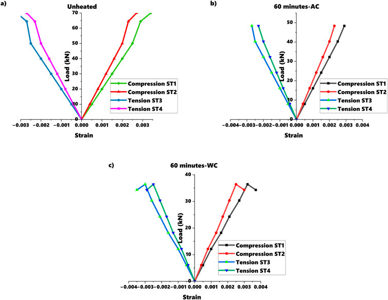
Figure 13. Load strain values of (A) reference, (B) section heated to 60 min and cooled down using air, (C) section heated to 60 min and cooled down using water.
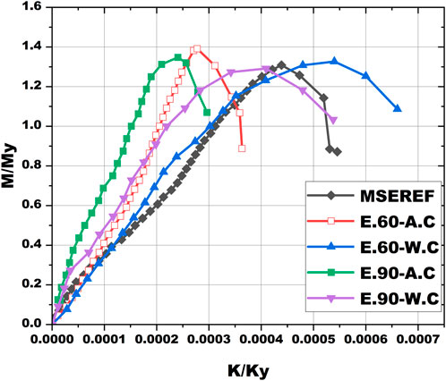
Figure 14. Moment rotation graph obtained for beam sections.
Where v1, v2, v3 are deflection values obtained from both loading points and deflection in the middle of the beam.
E and Iy are Elastic modulus and Second moment of area of gross cross section about its major axis respectively.
My is yield moment, L is the distance between two loading points.
The findings from the study reveal critical insights into the stiffness and deformation behavior of GI-based CFS built-up beams under elevated temperatures, which can significantly influence the design of fire-resilient structures. The observed trends in stiffness and deformation during the heating and cooling processes provide valuable implications for the structural design and fire safety of CFS beams in real-world applications.
One of the key observations in the study is the reduction in stiffness of CFS beams when exposed to elevated temperatures. This trend has important implications for the load-carrying capacity and deflection control of fire-resilient structures. As CFS beams undergo heating, their stiffness decreases due to material degradation (e.g., loss of yield strength and modulus of elasticity), which results in larger deflections under the same applied loads. This is especially critical for longer beams and structures subjected to service loads during or after a fire event.
Implications for Design: The stiffness degradation necessitates the use of over-designed sections or stiffer profiles to account for potential deflection limits during fire exposure. Fire-resistant coatings or insulation materials could be incorporated into the design to delay the stiffness reduction and maintain structural stability. Additionally, the use of stiffeners (such as Type II in this study) may help mitigate the effects of stiffness loss and improve the moment-carrying capacity during elevated temperatures.
The study also highlighted the differences in deformation between sections cooled using water and air. Water-cooled sections exhibited greater deformations due to the rapid temperature drop and induced thermal stresses. This finding suggests that rapid cooling methods can lead to greater residual deformations and structural distortion, potentially affecting the post-fire serviceability of the structure.
Implications for Design: Designers should consider the cooling method when evaluating the post-fire performance of CFS beams. In scenarios where rapid cooling methods are used, such as in fire-fighting operations, the residual deformations of CFS beams could impact the overall structural integrity. In such cases, structures may need to be designed with additional flexibility or reinforcement to accommodate post-fire movements and ensure continued load-carrying capacity.
The significant reduction in moment-carrying capacity observed in the study under higher heating durations further emphasizes the need to consider deformation limits when designing for fire resistance. As beams lose stiffness, they are more susceptible to buckling or excessive deflections, which can compromise the safety and serviceability of the structure during and after a fire event.
Implications for Design: Engineers should assess failure modes such as LTB and DB, which could occur more readily under fire exposure. This can be addressed by introducing adequate bracing or stiffening elements to prevent these failure modes, particularly in long-span beams. The design should also ensure that fire resistance ratings meet the required safety standards to account for the reduced strength of structural members under elevated temperatures.
The study’s findings also highlight the effectiveness of Type II stiffeners (sigma profile) in improving the moment capacity of CFS beams during fire exposure. The stiffeners helped reduce deformation and increase the load-carrying capacity, making them a valuable component for enhancing the fire resilience of CFS structures.
Implications for Design: The use of well-designed stiffeners in CFS beams can enhance the fire resistance by reducing DB and increasing the beam’s stability under elevated temperatures. It is essential to incorporate stiffener arrangements based on design requirements, such as the expected fire exposure time and structural load conditions, to ensure optimal performance under both normal and fire conditions.
The deformation trends observed in the study emphasize the importance of evaluating the structural integrity of CFS beams after a fire event. Excessive deformations or permanent deflections could affect the overall performance of the building, particularly in multi-story structures or critical load-bearing elements.
Implications for Design: Post-fire inspection should include the assessment of permanent deformations to ensure that the structural capacity is not compromised. This could involve monitoring deflections and residual strength after a fire event to determine whether additional reinforcement is needed for continued safe use.
The study observed a significant reduction in the stiffness and load-carrying capacity of GI-based CFS beams with increased heating durations. Specifically, the loss in stiffness was more pronounced.
Beams with type II web stiffeners exhibited the highest load-carrying capacity in all heating and cooling scenarios. This was followed by beams with C-sections, except when subjected to 90 min of heating and cooled using water. The use of sigma profile (such as type II) can be recommended in fire-exposed beam designs to enhance the load-carrying capacity. Engineers should consider stiffener configurations and profile as a means to improve structural stability during thermal exposure. The increase in load-bearing capacity provided by stiffeners is particularly critical in maintaining safety during fire events, where the load distribution may change due to material weakening.
The study revealed a marked decline in the ultimate moment capacity of the beams as the heating duration increased. Specifically, beams exposed to 90 min of heating showed strength losses of up to 47.56% when cooled with air and 60.33% when cooled with water. Engineers must consider the decrease in bending resistance over time when designing beams for fire scenarios. For buildings or structures exposed to prolonged high temperatures, the bending moments that the beams can withstand will be significantly reduced, especially when subjected to cooling methods that exacerbate thermal gradients (such as water cooling). To mitigate this, engineers should incorporate fire-resistant materials or coatings or increase the beam section to compensate for potential reductions in moment capacity.
As the heating duration increased, the deflection and moment capacity of the beams decreased, with major declines observed after 60 min of exposure. In structural fire engineering, it is crucial to evaluate the expected duration of fire exposure and its effect on the beam’s performance. For instance, a beam exposed to a fire for 90 min will show a drastic reduction in load-carrying capacity. Engineers should design for realistic fire scenarios, factoring in potential fire durations to ensure the structure can maintain stability during a fire event. For higher-risk applications, increasing the fire resistance through fire-rated coatings or incorporating additional reinforcement may be necessary.
The study emphasizes the negative impact of prolonged heating on structural integrity, particularly the loss of stiffness and moment capacity. Engineers should adopt proactive fire-resistance strategies to ensure safety under elevated temperatures. This includes the use of fire-resistant coatings, the optimization of structural geometry (e.g., using reinforced profiles), and consideration of cooling strategies. Additionally, the incorporation of fire-resistant materials such as gypsum or perlite coatings can help reduce the rate of temperature rise in CFS beams, thereby prolonging their strength and stability during a fire.
ABAQUS software (ABAQUS, 2018) was employed for parametric analysis and Finite Element Method (FEM) modelling of beam sections. In the ABAQUS simulations, identical dimensions, support conditions, and loading conditions as those implemented in the experimental setup were replicated to ensure consistency and accuracy in computational analysis. This approach facilitates the validation of numerical analysis. Figures 1A–C shows dimensions of all built up beam sections used for FEM. The initial step involves creating 2D representations of beam sections, which are then converted into 3D models for further analysis.
During the finite FE analysis conducted in ABAQUS, convergence was ensured through the following criteria.
Residual Forces and Displacements
The analysis employed the default convergence tolerance for residual force and displacement norms in ABAQUS. This criterion ensures that the numerical solution approaches equilibrium with minimal residual errors. The tolerance was set to
Energy Norm
The energy norm, which monitors the changes in strain energy during iterations, was also used as a secondary convergence check. The threshold was set to
Mesh Independence
A mesh refinement study was conducted to confirm that the results were independent of mesh density. The final mesh size was selected based on an acceptable trade-off between computational efficiency and accuracy, with minimal variations in results observed for further refinements.
Divergence Handling
In cases where convergence issues arose, particularly during large deformation or buckling stages, the analysis incorporated damping and adjusted the convergence controls to improve stability. The parameters were fine-tuned iteratively to ensure robust results.
Material properties utilized for the analysis of beam sections with different profiles were derived from temperature-dependent coupon test results (Sabu Sam et al., 2024c). Key parameters such as Young’s modulus, ultimate stress, yield stress, and Poisson’s ratio values were employed for the modelling process. Measured material properties, engineering stress strain values were converted into true stress and strain using the Equations 4, 5.
Where
S4R element is employed to model all components of CFS beam sections. Previous studies have established that the S4R element is widely used for modelling these types of beams. This element incorporates finite membrane strains and accommodates arbitrarily large rotations. The reduced integration (R) in S4R elements helps avoid problems related to shear locking that might arise in fully integrated elements, especially for thin structures. Moreover, S4R elements allow for effective representation of both large deformations and rotational behavior, which are critical for assessing buckling and stability under thermal loading. This makes it well-suited for conducting analyses involving large strains and addressing geometrically non-linear problems. The support at the ends and loading points application are modelled by using R3D4 elements.
The mesh size is a critical factor in FEM, as it directly affects both computation time and the accuracy of the obtained results. Consistent with prior research and literature (Roy et al., 2021), careful consideration is given to the selection of an appropriate mesh size for the analysis. Figure 15 depicts meshed up model of a beam section. A mesh convergence study was performed to ensure that the results were independent of mesh density. Mesh sizes ranging from 5 mm to 20 mm were tested, and the load-deflection curves, strain distributions, and failure modes were compared. The study revealed that a mesh size of 5 mm provided accurate results with less than 2% variation in the ultimate load compared to finer meshes, while maintaining computational efficiency. Mesh sizes between 5 mm and 12 mm are commonly used for thin-walled steel sections subjected to flexural and thermal loads, as demonstrated by Roy et al. (2021) who analyzed CFS beams with similar geometric and material properties. Studies such as Karthik and Anbarasu (2021), Sam et al. (2024d) and Sam et al. (2024a) also highlight that a 5 mm mesh size is adequate for capturing local buckling, DB, and LTB phenomena, which are critical to this study. The selected mesh size of 5 mm ensured that the web, flanges, and stiffener regions were adequately represented, capturing stress gradients and deformation patterns accurately, especially near the corners and stiffener locations.

Figure 15. Meshed up model of type II web stiffener.
Self-taping screws are modelled using interactions module. The interface between the overlapping elements of the constructed CFS beam sections was characterized using a surface-to-surface approach with a finite sliding formulation.
Reference points were defined at the center of loading and support plates for the application of loading and boundary conditions. In the meshing process, two node sets were established, specifying degrees of freedom for translation and rotation. The analysis commenced with a linear bifurcation analysis, followed by a nonlinear analysis incorporating the Riks method. Pinned and roller supports were implemented at both ends of the specimens. Eigenvalue analysis was conducted to consider geometric imperfections in the FE models. Critical buckling modes were identified through linear bifurcation analysis. In the nonlinear analysis, the Modified Riks technique was employed to capture complex behaviors and post-buckling responses.
Boundary condition assumptions play a critical role in the accuracy of FEM simulations, as they directly influence the predicted structural behavior under loading and elevated temperature conditions. In this study, pinned and roller supports were used to replicate the experimental setup, where rollers were positioned directly beneath the loading points. While this configuration closely aligns with typical test setups for structural beams, it is important to consider the following implications:
The boundary conditions assumed in the FEM analysis may differ from real-world structural scenarios where supports might not be perfectly pinned, or rollers might exhibit some degree of friction or rotation resistance. Such simplifications can lead to differences in:
• Stress distribution: Real-world supports may induce additional stresses due to friction or restraint, which are not captured in the idealized boundary conditions.
• Deformation patterns: Fixed or partially restrained supports might restrict certain deformation modes, altering the overall structural response.
The assumed pinned and roller supports may affect the predicted buckling modes:
• LTB: The roller condition might underestimate the restraint against lateral displacement, leading to conservative predictions of LTB.
• DB: The idealized boundary conditions could amplify distortional effects by not fully replicating support stiffness or restraint conditions.
Under fire conditions, support stiffness can change due to thermal expansion or deterioration of material properties at the supports. These factors might influence:
• Thermal stresses: Supports that expand or degrade under heating may redistribute loads and alter the stress field.
• Post-buckling behavior: Variations in support rigidity under heating may affect post-buckling stability and deformations, which are not fully accounted for in idealized FEM models.
The experimental results provide a crucial reference point to validate the FEM model. Any discrepancies between FEM and experimental outcomes can often be attributed to assumptions made regarding boundary conditions. The close agreement observed in this study indicates that the boundary condition assumptions, though idealized, reasonably captured the behavior of the tested sections.
The boundary conditions are applied to ensure realistic support conditions, and the loading is applied to simulate the experimental setup. The boundary conditions are described in terms of translation (U) and rotation (θ), which specify the allowable movements and rotations at each point in the model.
Translation (U): Translation refers to the displacement of nodes in the X, Y, and Z directions. In this study, we focus primarily on the vertical translation (U) since the beams are subjected to bending loads, which cause vertical deflections. The boundary conditions for translation are set as follows:
Pinned Support at One End (Node 1): The pinned support allows rotation but prevents translation in both the X and Y directions. Thus, the displacement in the X and Y directions is restricted at this node, while the Z direction translation is free, allowing vertical displacement.
Roller Support at the Other End (Node 2): The roller support allows translation in the X direction but prevents translation in the Y direction (vertical direction) and allows rotation about the Z-axis.
This configuration ensures that the beam can deflect under applied loads while maintaining the realistic boundary conditions associated with typical beam testing setups, such as those used in the experimental study.
Rotation (θ): Rotation describes the angular displacement around the X, Y, and Z-axes. In this study, the beam’s rotation is critical for capturing bending and potential buckling behavior under thermal exposure. The boundary conditions related to rotation are applied as follows:
Pinned Support (Node 1): Since the pinned support allows rotation but prevents translation, it restricts angular displacement about the Y and Z-axes. Rotation about the X-axis is free, allowing the beam to rotate under applied bending moments.
Roller Support (Node 2): At the roller support, the beam is free to rotate about the Z-axis (perpendicular to the plane of the beam) but is restricted from rotating about the X and Y-axes.
C channels were connected back-to-back using tie constraints in interaction. Ties were positioned using the same dimension used for sections tested experimentally. Figure 16 illustrates the failure mode of built-up beams with reference web stiffener, subjected to various temperatures and cooling methods. Results obtained through FE analysis were compared with experimental results, and a good level of agreement was observed between the two sets of data. Any disparities that emerge, were minimal in nature, indicating a strong correlation between the FE predictions and the experimental observations. In both experiments and FEM, DB was the predominant failure observed as seen in figures. Some local buckling was also seen at loading points on stiffeners provided.
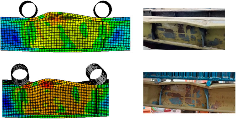
Figure 16. Comparison of failure modes between experiment and FEM.
Although the FEM results closely aligned with the experimental outcomes, some minor discrepancies were observed. These differences are discussed below, along with potential explanations and their implications.
The FEM predicted ultimate load values were slightly higher than those obtained experimentally. The FEM utilized average material properties (e.g., yield strength and elastic modulus) derived from tensile tests. Variability in material properties across specimens or within the same specimen might lead to slight underestimations of the actual resistance in the experiments. Idealized boundary conditions in the FEM (e.g., perfectly pinned or roller supports) may not fully capture the minor flexibility and rotational resistance of experimental setups. Although imperfections were incorporated into the FEM, their exact shape and magnitude may differ from those in the physical specimens, influencing the buckling behavior and load-carrying capacity.
The initial stiffness of the FEM results was marginally higher than that observed experimentally. Contact and Connection Modeling: In the experimental setup, self-tapping screws may introduce slight slippage or localized deformations at connections, reducing the initial stiffness. The FEM assumes ideal connections, leading to higher stiffness. Deflection measurements during experiments include potential errors due to instrument sensitivity or specimen alignment, introducing small variations in stiffness estimation.
While both experimental and FEM results identified DB as predominant failure modes, minor variations in the onset of these modes were noted. In experiments, small eccentricities or non-uniform loading might slightly alter the initiation of failure. The FEM assumes perfect symmetry in loading and geometry, leading to idealized predictions. Experimental imperfections may deviate from the assumed mode shapes in the FEM, influencing failure initiation and progression. The minor discrepancies highlight the inherent challenges in modeling real-world behaviors using numerical methods. They underscore the importance of validating FEM results with experimental data to ensure reliability. These differences, though minimal, emphasize the need for careful consideration of boundary conditions, material variability, and thermal effects when using FEM for design or parametric studies.
Parametric analysis was done on beam sections with different web stiffeners to stimulate same heating and cooling methods done for beams which were analyzed through experiment. In this study, the chosen variables were selected based on their relevance to real-world structural applications and their potential to provide meaningful insights into the flexural behavior of CFS built-up beams under fire and cooling conditions. The following criteria guided the selection of the parametric study variables:
Real-World Relevance: The heating durations represent typical fire scenarios as specified in design codes, such as the ISO 834 fire curve (ISO 834-1, 1999), which is widely used for modeling the thermal effects of fires in buildings. These durations correspond to different stages of fire exposure, from initial heating to prolonged exposure, which are critical for understanding the material performance during actual fire events.
Objective: By studying different heating durations, engineers can evaluate the performance of CFS beams under varying fire intensities and assess the thermal degradation over time.
Real-World Relevance: Cooling methods are important for evaluating how structures behave when exposed to fire suppression efforts. In real-world scenarios, structures might undergo rapid cooling due to water spray or slower cooling due to air exposure.
Objective: The comparison of these two cooling methods allows for a comprehensive analysis of how the rapid cooling (water-cooled) versus slower cooling (air-cooled) impacts the post-fire behavior, specifically in terms of strain, deformation, and moment capacity.
Real-World Relevance: Stiffeners are commonly used in CFS structural elements to enhance stability and resistance to local buckling and DB. Different stiffener types and profiles are employed in practice depending on the specific load-bearing requirements of the structure and the expected fire exposure conditions.
Objective: The inclusion of different stiffener types allows for evaluating their effectiveness in improving the fire performance of CFS beams and understanding how stiffeners can be optimized for better post-fire strength and stability.
Real-World Relevance: Lipped channel profiles are frequently used in CFS construction due to their efficiency and ease of fabrication. The study focuses on these profiles to better understand how their design and geometry influence the beam behavior under fire exposure.
Objective: The geometry of the section plays a key role in the overall load-carrying capacity and failure modes, particularly under elevated temperature conditions. This is critical for designing CFS beams that are both efficient and fire-resistant.
By focusing on these variables, the study aims to bridge the gap between experimental findings and practical applications in structural design. The parametric study helps to provide valuable insights for improving the fire-resistance design of CFS beams in real-world fire scenarios and supports the optimization of materials and design practices in fire-prone environments. Figures 17, 18 shows failure modes of beam sections with type I and II web stiffeners. Like experimental beams, for these modelled beams also, vertical stiffeners were provided at loading points and supports to arrest the beams in order to avoid LTB. Local buckling was noted at these stiffeners after loading as observed in experiment. Since stiffeners were provided at supports, it was not allowed to rotate freely and thus avoided LTB Jaya kumar et al. (2023), Amali and Anbarasu (2024). Both profiles were having DB as their failure mode similar to built up beams with reference web stiffener. It is a mode of failure in thin-walled members subjected to flexural loading which involves local distortions or warping of the cross-section which is more susceptible to sections with high slenderness ratio.
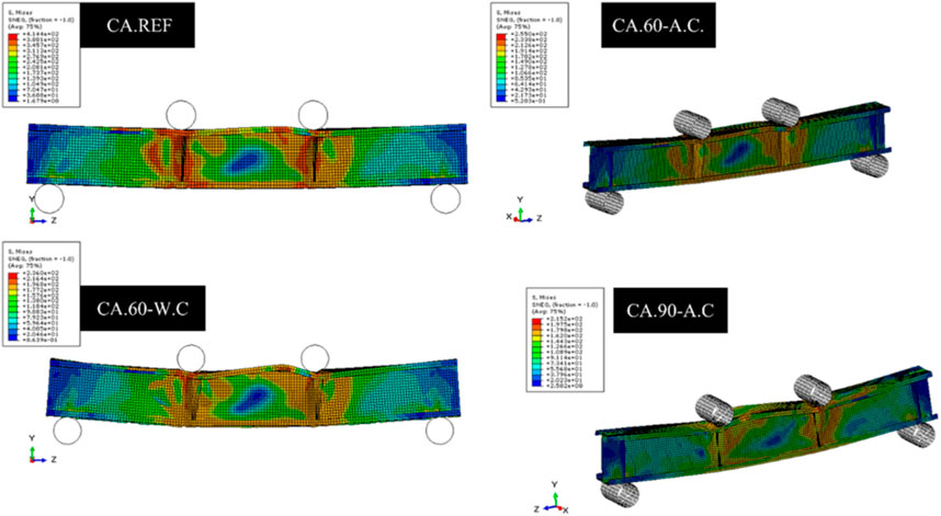
Figure 17. Failure mode of beams with type I stiffener.
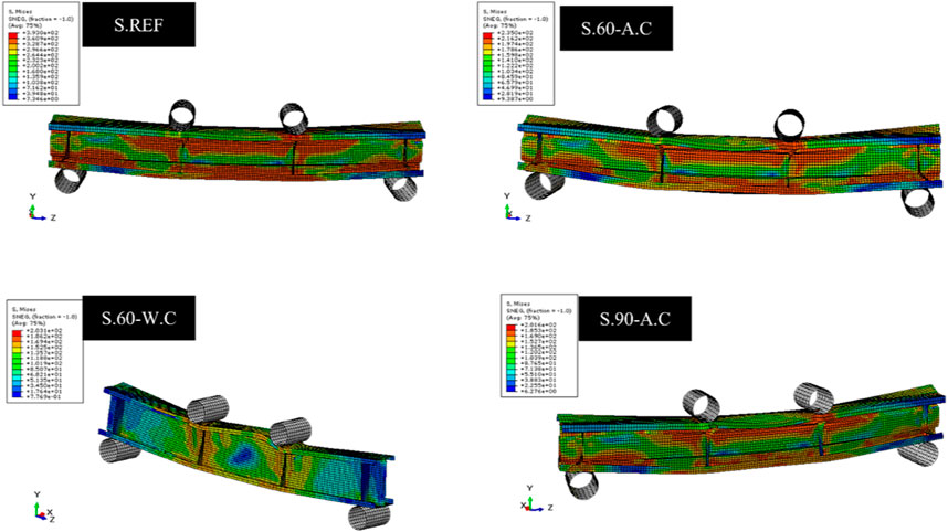
Figure 18. Failure mode of beams with type II stiffener.
Figure 19 depicts comparison of moments obtained through FEM analysis of beam sections with all stiffener types. Moment is provided in kNm and duration of heating is mentioned in minutes and method of cooling is denoted by AC for air cooling and WC for water cooling. Built up beams with type II web stiffener sections are clearly having highest moment capacity than other beam sections in all durations of heating and cooling. Built up beams with reference stiffener comes second except in case of 90 min of heating and cooling down using water. In that particular case alone, built up beams with type I web stiffener section comes in second after type II web stiffener in terms of moment capacity. In all other cases, built up beams with type I web stiffener have the least load carrying capacity. Among unheated sections, built up beams with type II web stiffener is having a moment of 22.88 kNm, which is 29.89% and 31.69% higher than reference and built-up beams with type I web stiffener respectively. For the same durations of heating, sections which were cooled down using water is having more loss of moment than sections cooled using air. In 60 min of heating, built up beams with type II web stiffener cooled using air is having a moment of 14.22 kNm, which is 26.44% higher than 10.46 kNm, moment obtained by built up beams with reference web stiffener. For the same case, there is a difference of 11.85% observed between reference and built-up beams with type I web stiffener. In 90 min of heating and cooling down using water, built up beams with type I web stiffener profile is having 8.75% more moment capacity than built up beams with reference web stiffener. Sabu Sam et al. (2024a) found that Zed profiles perform better than other unsymmetrical profiles under fire scenarios due to their enhanced flexural rigidity. Similarly, this study observed that the type II stiffener outperforms type I and reference sections, highlighting the importance of profile geometry in resisting thermal stresses.
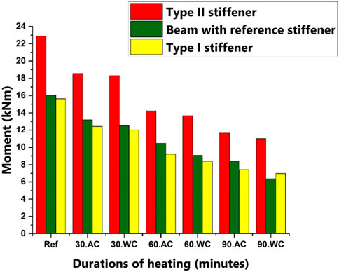
Figure 19. Comparison of loads for beam sections of all profiles.
The sigma-shaped profile (Type II stiffener) provides a more efficient distribution of material and enhances the beam’s ability to resist LTB under elevated temperatures. The cross-sectional shape of the sigma stiffener offers greater resistance to DB and local buckling compared to the C with inclined flanges profile, especially when subjected to fire conditions. The geometry of the sigma profile allows it to better distribute the applied loads and resist lateral deformations. The sigma profile has a higher section modulus in the direction of bending, which leads to increased moment resistance. This is crucial under both ambient and elevated temperature conditions, as it results in greater flexural rigidity. The additional web area and reinforcement along the flanges improve overall stiffness compared to the C with inclined flanges profile (Type I stiffener), leading to higher load-carrying capacity. Type II stiffener has a design that promotes better thermal distribution during heating, leading to more uniform temperature rise across the section. This uniform thermal behavior helps in reducing thermal gradients, which in turn minimizes residual stresses after cooling. This is particularly beneficial during rapid cooling, where thermal stress concentrations could otherwise lead to higher deformation. Due to its improved structural efficiency, type II exhibits better thermal stability under prolonged heating conditions. The increased moment capacity during cooling processes (especially water cooling) indicates the greater resilience of type II stiffeners to fire-induced degradation, allowing them to recover faster from thermal exposure compared to Type I stiffeners.
Type II stiffeners offer enhanced resistance to both DB and local buckling under fire exposure. The geometrical design of the sigma profile or type II stiffener provides more robust support to the webs and flanges, making it more resistant to distortion under both fire and cooling conditions. This feature contributes significantly to the stiffness and strength of the beam, especially in high-temperature environments. Type I, on the other hand, has a less effective geometry for preventing DB under fire conditions, as its inclined flanges create more vulnerabilities in the structural integrity of the beam. This is evident in the tests, where the sigma profile’s better resistance to local and DB leads to higher load-carrying capacity across all test conditions.
The sigma like profile optimizes material usage by placing the stiffener flanges in areas where they can resist more bending, which improves the overall strength-to-weight ratio. This enables the beam to better resist high strain values without experiencing the same level of plastic deformation as Type I stiffeners, especially under prolonged heating and cooling conditions. The increased resistance to deformation in Type II stiffeners is reflected in lower strain values compared to Type I stiffeners under all test conditions. This efficiency contributes to better long-term performance under both fire exposure and normal loading conditions, supporting the sigma profile’s superior performance in terms of both ultimate moment capacity and post-fire recovery. The sigma profile’s design is particularly advantageous in preventing thermal distortions under high-temperature conditions. This allows the beam with Type II stiffeners to maintain its structural integrity more effectively when exposed to elevated temperatures. This characteristic enhances the beam’s performance under fire conditions, where maintaining geometrical stability is critical for preventing excessive deflections and failures. Sigma like shape also provides a larger moment of inertia, which contributes to increased stiffness and strength. It also has a more efficient cross-sectional shape for resisting bending loads compared to the other 2 beam sections. The geometry of the profiles influences the distribution of material in the cross-section, affecting how effectively the profile can resist bending stresses.
The theoretical analysis of the results considers the configuration of the built-up member and its connection (CUFSM, 2018). Determining the effective area using the effective width method proves challenging due to the nature of the built-up member and the intermittent connection. Moreover, codal provisions lack specific guidelines for designing members post-fire, primarily due to the difficulty in ascertaining temperature distribution across the members, whether uniform or non-uniform. As a workaround, coupon results are utilized for post-fire member design. The Direct Strength Method (DSM) emerges as the most straightforward approach for comprehending buckling analysis of members. This method involves determining section properties and conducting elastic buckling analysis, typically facilitated by software such as CUFSM. Consequently, this section evaluates the conservativeness of DSM. DSM is applied to ascertain the design moment capacities of structural members. Sectional properties are vital for the analysis, and they are derived from coupon tests. Buckling analysis is performed using specialized software such as CUFSM (Sabu Sam et al., 2024b). The Equations 6–8 utilized in the DSM method are sourced from (AISI S100-16, 2016) and are outlined below. Table 3 shows moments calculated for all sections using DSM method and using loads obtained through FEM and experiment. Mean and coefficient of variation is calculated and displayed in the table. Figure 20 display FCR values obtained in CUFSM of beams with different profiles.
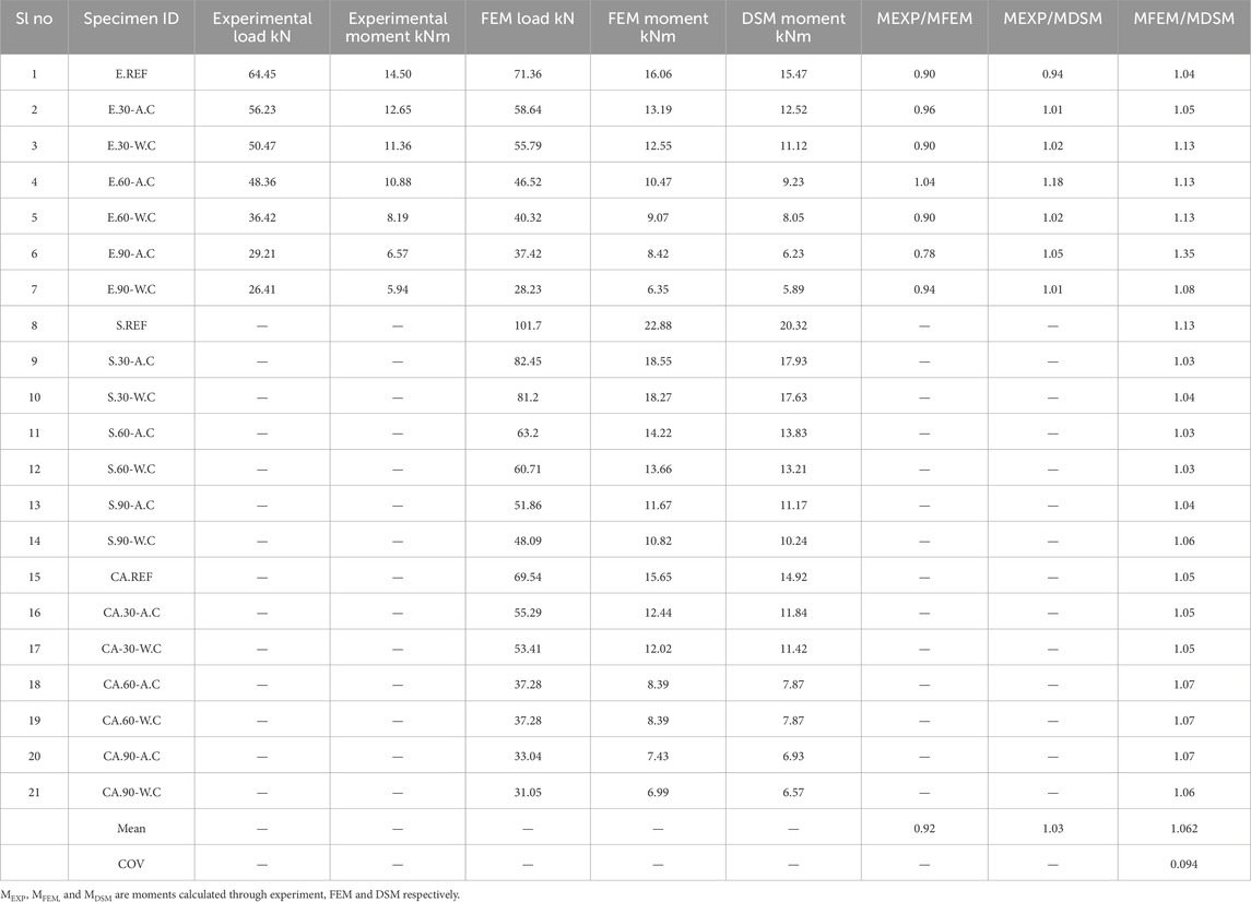
Table 3. Load and moment calculations for experimental, FEM load, and DSM.

Figure 20. FCR values obtained for beams with all types of stiffeners.
Where,
In this research paper, a comprehensive analysis is conducted for GI based CFS built up beams with reference web stiffener, exposed to elevated temperatures and subsequently cooled using both water and air. The beams are subjected to a four-point loading configuration to meticulously investigate their flexural behavior. The grade of steel employed in this study is E 350. Experimental data are collected and subsequently validated through FEM. Parametric studies are carried out for two categories of beams: those equipped with type I and type II web stiffeners. Manual calculations of the moments for these beams are performed using DSM, and the results are compared.
• DB is observed in beams as a result of the effects of thermal expansion and differential thermal stresses.
• Built up beams with type II web stiffener are clearly having highest load carrying capacity than other profiles in all durations of heating and cooling. C sections profile comes second except in case of 90 min of heating and cooling down using water.
• A major decline in moment was noted from 60 min of duration. For 60 min of heating and cooling down using air, a loss of 33.26% was noted in comparison with unheated section. For the section cooled down using water, loss calculated was 76.93%.
• Lateral deformations exhibit an increasing trend for specimens subjected to longer durations of heating.
• The maximum stiffness is observed in the reference specimen, while the least stiffness is observed in the beam specimen heated for 90 min and cooled down using water. Stiffness gradually decreases as the duration of heating is increased.
Assumptions made in this study.
Material Homogeneity:
• Assumption: The material properties of the GI-based CFS sections, including yield strength and modulus of elasticity, were assumed to be uniform throughout the specimens.
• Potential Impact: Real-world variations in material properties could result in localized weaknesses or differences in performance that are not captured in this study. This might affect the direct applicability of results to other batches or grades of material.
Boundary Conditions in FEM:
• Assumption: Idealized pinned and roller boundary conditions were used in the FEM model to replicate the experimental setup.
• Potential Impact: These simplified conditions may not fully represent real-world scenarios where imperfections or flexibility at supports could influence load distribution and deformation.
Geometric Imperfections:
• Assumption: Initial geometric imperfections for type I and II stiffeners were estimated based on literature and incorporated into the FEM model.
• Potential Impact: While these imperfections align with standard practice, actual imperfections in manufactured sections might vary, potentially altering buckling behavior.
Cooling Protocol:
• Potential Impact: In real fires, temperature gradients and uneven cooling might occur, leading to more complex stress distributions and deformation patterns than those observed in this study.
Applicability to Other Beam Lengths and Loading Conditions:
• Assumption: The findings for the beam lengths and four-point loading configuration tested in this study are representative of broader structural scenarios.
• Potential Impact: Variations in beam length, span-to-depth ratio, or different loading configurations could alter failure modes, stiffness, and deformation trends, limiting the generalizability of the results.
Practical Recommendations
1. Design Considerations for Elevated Temperatures:
• Engineers should prioritize the use of type II stiffeners for applications requiring enhanced load-carrying capacity and thermal resilience. Their superior performance under both ambient and elevated temperatures makes them a suitable choice for fire-resilient structures.
• The study highlights the vulnerability of CFS beams to significant stiffness and moment capacity loss after prolonged heating. Structures exposed to fire for durations exceeding 60 min may require additional reinforcement or alternative designs.
2. Post-Fire Structural Assessments:
• For water-cooled beams, engineers should account for the increased deformations and strain levels induced by rapid cooling, as these could compromise structural stability. Sections subjected to water cooling may require stricter post-fire inspection protocols and potential retrofitting.
3. Incorporation into Design Codes:
• Design code committees are recommended to update fire-resistance provisions for CFS built-up beams by incorporating guidelines for stiffener selection and their impact on flexural performance.
• The findings on stiffness trends and buckling behavior should be used to refine safety factors and thermal performance criteria for fire-exposed structures.
4. Material and Configuration Optimization:
• Further investigations into alternative stiffener designs and materials that minimize thermal degradation could complement the current findings, providing engineers with a broader range of solutions for fire-resilient construction.
By addressing these practical aspects, the study offers valuable insights into enhancing the fire resistance of CFS built-up beams, contributing to safer and more resilient structural designs.
Based on the findings and limitations of this study, several avenues for future research can be identified to further enhance the understanding and applicability of GI-based CFS built-up beams under elevated temperatures:
1. Cyclic Loading Tests:
• Investigating the behavior of GI-based CFS beams under repeated or cyclic loading after exposure to elevated temperatures would provide insights into their fatigue performance. This is critical for structures subjected to dynamic or fluctuating loads, such as those in seismic zones or industrial facilities.
2. Real-Scale Fire Scenarios:
• Conducting large-scale fire tests that simulate real-world fire scenarios, including uneven heating and cooling conditions, would help validate the applicability of laboratory findings. Such studies could also consider the effect of fire suppression methods, such as sprinklers, on the thermal and structural response of the beams.
3. Longer Durations and Variable Cooling Rates:
• Extending the study to include heating durations beyond 90 min and exploring intermediate cooling rates could provide a more comprehensive understanding of fire-induced behavior. These scenarios would better reflect conditions in prolonged or partially controlled fires.
The original contributions presented in the study are included in the article/supplementary material, further inquiries can be directed to the corresponding author.
VS: Data curation, Formal Analysis, Investigation, Software, Writing–original draft. NA: Conceptualization, Project administration, Supervision, Writing–review and editing. CH: Writing–review and editing, Investigation, Formal analysis, Methodology. Mab: Writing–review and editing, Formal analysis, Validation, Visualization. Maz: Writing–review and editing, Supervision, Project administration, Resources.
The author(s) declare that no financial support was received for the research, authorship, and/or publication of this article.
The authors would like to thank Karunya Institute of Technology and Sciences for letting us carry out the work.
The authors declare that the research was conducted in the absence of any commercial or financial relationships that could be construed as a potential conflict of interest.
The author(s) declare that no Generative AI was used in the creation of this manuscript.
All claims expressed in this article are solely those of the authors and do not necessarily represent those of their affiliated organizations, or those of the publisher, the editors and the reviewers. Any product that may be evaluated in this article, or claim that may be made by its manufacturer, is not guaranteed or endorsed by the publisher.
AISI S100-16 (2016). North American cold-formed steel specification for the design of cold-formed steel structural members. Washington, DC: American Iron and Steel Institute.
Amali, D., and Anbarasu, M. (2024). Behaviour and design of cold-formed steel built-up I-beams composed of four channels. J. Constr. Steel Res. 217, 108671. doi:10.1016/j.jcsr.2024.108671
Baddoo, N., and Francis, P. (2014). Development of design rules in the AISC Design Guide for structural stainless steel. Thin-Walled Struct. 83, 200–208. doi:10.1016/j.tws.2014.02.007
Chen, Z., Huang, Y., and Young, B. (2022). Design of cold-formed ferritic stainless steel RHS perforated beams. Eng. Struct. 250, 113372. doi:10.1016/j.engstruct.2021.113372
Dai, Y., Roy, K., Fang, Z., Chen, B., Raftery, G. M., and Lim, J. B. P. (2022). A novel machine learning model to predict the moment capacity of cold-formed steel channel beams with edge-stiffened and un-stiffened web holes. J. Build. Eng. 53, 104592. doi:10.1016/j.jobe.2022.104592
EN 1991-1-2 (2002). Eurocode 1: actions on structures - Part 1-2: general actions - actions on structures exposed to fire. Brussels: European Committee for Standardization.
Huang, Y., and Young, B. (2018). Structural performance of cold-formed lean duplex stainless steel beams at elevated temperatures. Thin-Walled Struct. 129, 20–27. doi:10.1016/j.tws.2018.03.031
ISO 834-1 (1999). Fire-resistance tests - elements of building construction - Part 1: general requirements. ISO Stand.
Jaya kumar, G., Kiran, T., Anand, N., Anbarasu, M., and Lubloy, E. (2023). Post-fire flexural behaviour and performance of unrestrained cold-formed steel built-up section beams: experimental and numerical investigation. Case Stud. Constr. Mater. 18 (Jul), e01978. doi:10.1016/j.cscm.2023.e01978
Karthik, C., and Anbarasu, M. (2021). Cold-formed ferritic stainless steel closed built-up beams: flexural behaviour and numerical parametric study. Thin-Walled Struct. 164, 107816. doi:10.1016/j.tws.2021.107816
Niemiro-Maźniak, J., and Lacki, P. (2024). Experimental and numerical analysis of joints and thin-walled steel beams fabricated through resistance spot welding and hot-dip galvanizing. Thin-Walled Struct. 202, 112105. doi:10.1016/j.tws.2024.112105
Prabowo, A., Huang, Y., and Young, B. (2023). Cold-formed stainless steel beams with single web hole at elevated temperatures. Thin-Walled Struct. 195, 111321. doi:10.1016/j.tws.2023.111321
Roy, K., Ting, T. C. H., Lau, H. H., and Lim, J. B. P. (2018). Effect of thickness on the behaviour of axially loaded back-to-back cold-formed steel built-up channel sections - experimental and numerical investigation. Structures 16, 327–346. doi:10.1016/j.istruc.2018.09.009
Roy, K., Ho Lau, H., Ting, T. C. H., Chen, B., and Lim, J. B. P. (2021). Flexural behaviour of back-to-back built-up cold-formed steel channel beams: experiments and finite element modelling. Structures 29, 235–253. doi:10.1016/j.istruc.2020.10.052
Sabu Sam, V., Adarsh, M., Lyngdoh, G. R., Marak, G. W. K., Anand, N., Al-Jabri, K., et al. (2023). Influence of elevated temperature on buckling capacity of mild steel-based cold-formed steel column sections– experimental investigation and finite element modelling. J. Struct. Fire Eng. 15, 314–337. doi:10.1108/JSFE-08-2023-0033
Sabu Sam, V., Anand, N., Kumar, R., and Andrushia, D. (2024a). Influence of section profiles on flexural behavior of unsymmetrical cold formed steel sections – analytical and numerical investigation. J. Struct. Fire Eng. 16, 1–36. doi:10.1108/JSFE-05-2024-0009
Sabu Sam, V., Anand, N., Lublóy, É., and Andrushia, D. (2024b). Investigation on key influencing factors affecting temperature distribution in concrete. Period. Polytech. Civ. Eng. 69, 220–230. doi:10.3311/PPci.37355
Sabu Sam, V., N, A., K Marak, G. W., Lyngdoh, G. R., Alengaram, J., and Andrushia, D. (2024c). Investigation on residual mechanical properties of galvanized iron cold-formed steel sections exposed to elevated temperatures. Electron. J. Struct. Eng. 24 (1), 53–59. doi:10.56748/ejse.24439
Sabu Sam, V. (2022). “Nano silica particles as A structural build up agent for 3D printing cement paste with additional accelerators,” in Materials Research Proceedings, Millersville PA. 231–237. doi:10.21741/9781644901953-26
Sam, V. S., Nammalvar, A., Andrushia, D., Gurupatham, B. G. A., and Roy, K. (2024a). Flexural behavior of galvanized iron based cold-formed steel back-to-back built-up beams at elevated temperatures. Buildings 14 (8), 2456. doi:10.3390/buildings14082456
Sam, V. S., Marak, G. W. K., Nammalvar, A., Andrushia, D., Gurupatham, B. G. A., and Roy, K. (2024b). Investigation on flexural behavior of galvanized cold-formed steel beams exposed to fire with different stiffener configurations. Fire 7 (9), 318. doi:10.3390/fire7090318
Sam, V. S., Anand, N., and Naser, M. Z. (2024c). Flexural behavior of cold-formed mild steel beams with web holes exposed to high temperature: analytical and experimental investigation. Innov. Infrastruct. Solut. 9 (10), 392. doi:10.1007/s41062-024-01710-3
Sam, V. S., Anand, N., Abdallah, M., Ei Hachem, C., Azab, M., and Andrushia, D. (2024d). Post fire flexural behavior of mild steel based cold-formed built-up beams exposed to elevated temperature. Front. Built Environ. 10, 1466935. doi:10.3389/fbuil.2024.1466935
Shakarami, M., Zeynalian, M., and Ataei, A. (2023). Numerical study of the behavior of friction-grip bolted shear connectors in composite beams with cold-formed steel sections. Thin-Walled Struct. 184, 110539. doi:10.1016/J.TWS.2023.110539
Wan, H. X., Huang, B., and Mahendran, M. (2021). Experiments and numerical modelling of cold-formed steel beams under bending and torsion. Thin-Walled Struct. 161, 107424. doi:10.1016/J.TWS.2020.107424
Keywords: cold-formed steel, galvanized iron, flexural behavior, finite element analysis, direct strength method, built-up beam, elevated temperature, post fire tests
Citation: Sam VS, Anand N, EL Hachem C, Abdallah M and Azab M (2025) Influence of profile on fire performance of cold-formed galvanised iron built-up section with bolted connection under standard fire temperature. Front. Built Environ. 11:1525141. doi: 10.3389/fbuil.2025.1525141
Received: 08 November 2024; Accepted: 04 February 2025;
Published: 12 March 2025.
Edited by:
M. Anbarasu, Government College of Engineering Dharmapuri, IndiaReviewed by:
Showkat Ahmad Kumar, Islamic University of Science and Technology, IndiaCopyright © 2025 Sam, Anand, EL Hachem, Abdallah and Azab. This is an open-access article distributed under the terms of the Creative Commons Attribution License (CC BY). The use, distribution or reproduction in other forums is permitted, provided the original author(s) and the copyright owner(s) are credited and that the original publication in this journal is cited, in accordance with accepted academic practice. No use, distribution or reproduction is permitted which does not comply with these terms.
*Correspondence: N. Anand, bmFuYW5kQGthcnVueWEuZWR1
Disclaimer: All claims expressed in this article are solely those of the authors and do not necessarily represent those of their affiliated organizations, or those of the publisher, the editors and the reviewers. Any product that may be evaluated in this article or claim that may be made by its manufacturer is not guaranteed or endorsed by the publisher.
Research integrity at Frontiers
Learn more about the work of our research integrity team to safeguard the quality of each article we publish.