- 1Graduate School of Urban Environmental Sciences, Tokyo Metropolitan University, Hachioji, Japan
- 2Faculty of Environmental and Urban Engineering, Kansai University, Suita, Osaka, Japan
- 3Graduate School of Engineering, Kyoto University, Kyoto, Japan
- 4IRIDeS, Tohoku University, Sendai, Japan
- 5College of Engineering, Nihon University, Tokyo, Japan
- 6Faculty of Engineering, Tohoku Gakuin University, Sendai, Japan
- 7Graduate School of Engineering, Osaka Metropolitan University, Osaka, Japan
- 8Graduate School of Agriculture, Kyoto University, Kyoto, Japan
- 9Pulchowk Campus, Institute of Engineering, Tribhuvan University, Kirtipur, Nepal
A low-cost rolling base isolation system (RBIS) for rubble stone masonry buildings in the Himalayan mountain range was presented and the feasibility of RBIS in the initial conditions installed in the buildings were evaluated in experiments and simple numerical simulations. The base isolation layer is composed of styrofoam, concrete slab and cast-iron balls. The styrofoam and concrete slab are the upper and lower elements of the isolation layer. The styrofoam boards are used for the embedment of the cast-iron balls and form panels for the casting concrete of the tie beams above the isolation layer. In the case of large earthquakes, these balls roll and horizontally squeeze into the styrofoam boards. The proposed RBIS satisfies two issues for the base isolation system in rubble stone masonry buildings in the Himalayan Mountain range; i.e. (i) use of locally available materials in the isolation layer and (ii) simple construction procedure of the isolation layer by local workers. The quasi-static cyclic loading experiments were conducted. The rolling coefficients of the RBIS were 0.06–0.14. Shaking table experiments were also conducted. It was found that the recorded maximum accelerations are approximately 0.2g. The restoring force characteristics of RBIS in the shaking table experiment were created and the behavior of the experiment was simulated by the response history analyses (RHAs). The behavior of the rubble stone masonry building associated with RBIS under large earthquakes was also evaluated in RHAs. Assuming that the traditional masonry buildings can resist the earthquake ground motions with a PGA under 0.15g, the buildings installed with RBIS can resist the ground motions with a PGA under 0.5g.
1 Introduction
Most buildings in rural areas in the Himalayan Mountain range are constructed using rubble stone masonry. These non-engineered masonry buildings are vulnerable to large earthquakes (Takagi and Wada, 2018; Ali et al., 2013; Goda et al., 2015; Wang et al., 2018); however, there are few alternative structural systems for the buildings in these areas, where financial and construction resources are limited. The roads to access these areas are unpaved and rough. Transportation is difficult, and consequently the buildings are constructed with local materials by the residents rather than professional workers. There is a significant amount of past research focusing on improving the seismic performance of these masonry buildings in terms of design recommendations and strengthening methods (Bothara and Brzev, 2011; Schildkamp and Araki, 2019a; Schildkamp and Araki, 2019b; Schildkamp et al., 2020; Schildkamp et al., 2021; Shrestha et al., 2020; Parajuli et al., 2020; Gautam et al., 2022; Khadka et al., 2023; Borri et al., 2012; Sathiparan et al., 2012; Triantafillou, 1998). By utilizing the knowledge obtained in these efforts, the seismic risks of these masonry buildings are significantly reduced; however, their actual seismic strength remains uncertain due to the high variability in construction materials and skills. Considering such uncertainty, introducing a low-cost base isolation layer at the interface between the superstructure and foundation is effective. It reduces the inertial forces induced on the superstructures during large earthquakes. This countermeasure is advantageous because the superstructures can be constructed in a similar way to the conventional procedures. There is a large amount of literature regarding the low-cost base isolation system developed for these non-engineered masonry buildings (Qamaruddin et al., 1986; Kelly, 2002; Nanda et al., 2015; Tsiavos et al., 2021; Ali et al., 2022; Galano and Calabrese, 2023; Md et al., 2023; Nanda et al., 2012; Nanda et al., 2015; Tsiavos et al., 2019; Losanno et al., 2021; Losanno et al., 2022; Zhang et al., 2021; Hadad et al., 2017). The friction coefficients examined in these past studies typically range from 0.05 to 0.2, which are sufficient to provide a substantial base-isolation effect. On the other hand, there are two issues deliberated for application of these base isolation systems to the rubble stone masonry buildings in the Himalayan Mountain range; i.e. (i) use of locally available materials in the isolation layer and (ii) simple construction procedure of the isolation layer by local workers. Locally available materials or relatively light materials in small amounts available in nearby cities must be used for the compositions of the isolation layer. Also, the installation procedure of the isolation layer must be simple enough for local workers to grasp. Casting and demolding work of the cast-in-situ reinforced concrete (RC) tie beams is especially well considered because the on-site construction procedures are often different from those for specimens in laboratories.
We proposed a low-cost sliding base isolation layer applicable to rubble stone masonry buildings in the Himalayan Mountain range, and investigated its feasibility (Suzuki et al., 2024). The sliding layer is composed of styrofoam, concrete slab, and grease as the upper element, the lower element and lubricant, respectively. Cement, styrofoam and grease are available in nearby cities and can be transported to the construction site. The styrofoam functions as the form panel for the cast-in-situ concrete of RC tie beams. The proposed sliding layer is developed for installation in important buildings for the local community such as schools. The quasi-static and shaking table experiments were conducted under varied conditions: e.g. grease amount, grease type, vertical stress, roughness of concrete slab surface and input motions. The recorded dynamic friction coefficient ranged from 0.08 to 0.16. Under the prerequisites of proper construction of the superstructures, i.e. placement of reinforcement and use of cement mortar, the sliding system can enhance the seismic performance of such important facilities.
In this paper, an alternative composition of the low-cost base isolation layer applicable to the rubble stone masonry buildings in the Himalayan Mountain range is presented. The previously proposed composition of the low-cost base isolation layer is revised, considering the concern of long-term change in lubrication such as penetration of grease into the concrete foundation. The lubricant is not used in the system presented here. The system satisfies the abovementioned two important issues for the application to local buildings, i.e. (i) use of locally available materials in the isolation layer and (ii) simple construction procedure of the isolation layer by local workers. The base isolation layer is composed of cast iron balls and styrofoam board for the upper elements, and concrete slab for the lower elements. The styrofoam is used for both the embedment of the cast iron balls and form panel for the concrete casting. There is existing theoretical and experimental research using balls for the isolation bearing (Zhou et al., 1998; Vecchio et al., 2022; Foti et al., 2012). However, the limited research focuses on application to the buildings in developing countries (Katsamakas et al., 2023). Quasi-static and shaking table experiments were conducted. Also, simple simulations were performed for investigating the seismic response of the school buildings with installation of the proposed system. The applicability is discussed. Although less long-term influence is expected in the system, this research primarily focuses on the performance in the initial building condition, and durability and long-term effect are beyond the scope of this research.
2 Low-cost rolling base isolation system
2.1 School buildings in Himalayan Mountain range
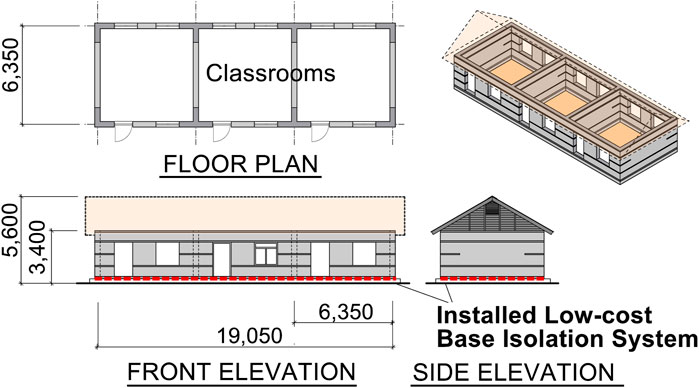
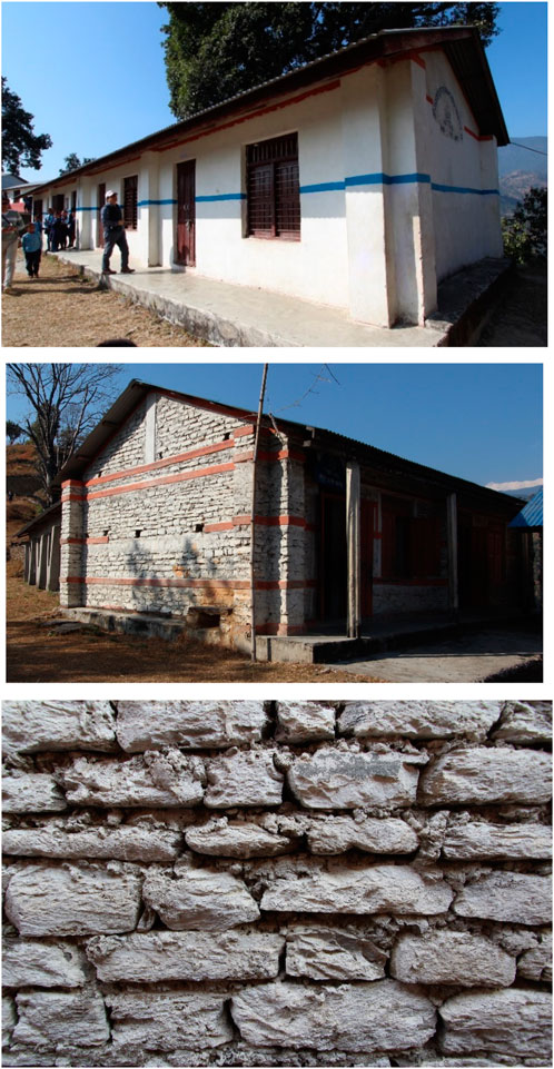
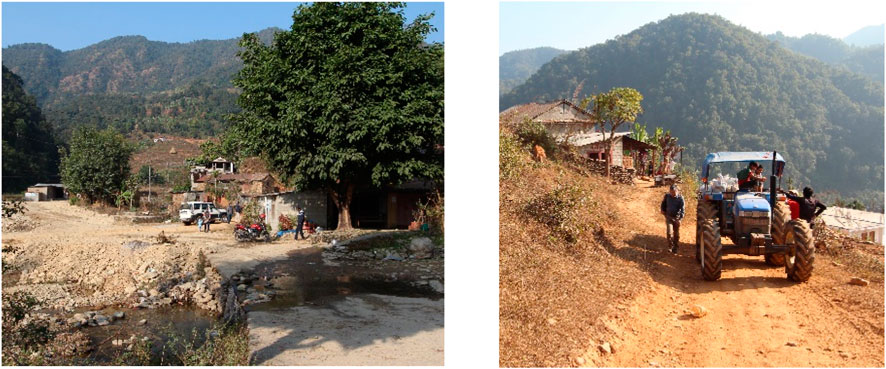
The low-cost rolling base isolation system (RBIS) installed in the rubble stone masonry school buildings in rural areas in the Himalayan mountain range is shown in Figure 1. Except for the RBIS introduced at the bottom of the walls, the building composition and configuration are identical to real elementary schools (Figure 2) constructed in the mountainous regions by (Schildkamp and Araki, 2019b). The roads to access these schools are unpaved and rough as shown in Figure 3. Therefore, extra construction materials used for introducing the RBIS are restricted to being lightweight with small volume. The compositions of the proposed RBIS are developed considering such restriction in the materials used. The details of the superstructures of the constructed elementary schools by Schildkamp et al. are shown in the literature (Schildkamp and Araki, 2019a; Schildkamp and Araki, 2019b). We investigated the damages to these school buildings after the Gorkha earthquakes, and found that these buildings were almost intact although significant damages such as failure of the walls in out-of-plane direction were observed in the rubble stone masonry buildings nearby. Through this investigation, it was found that properly constructed masonry buildings by educated construction workers under good supervision can assure a certain level of seismic performance. The PGA at these buildings under the Gorkha earthquake is unknown due to the lack of records. The PGA recorded relatively close to the buildings was approximately 0.15g (Goda et al., 2015). Using this limited information, the proposed base isolation system is evaluated assuming that the superstructure can resist earthquakes with a PGA of 0.15g.
2.2 Composition and construction procedure of RBIS
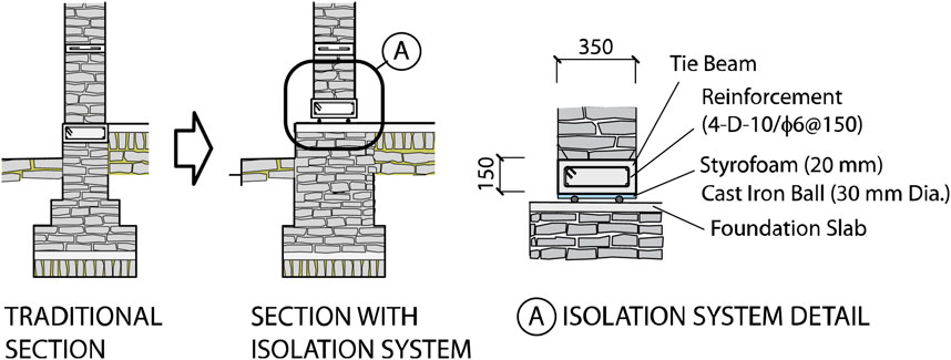
The section details of the wall bottom of the rubble stone masonry school building in Figure 1 are shown in Figure 4. The section details of the constructed buildings by Schildkamp et al. are shown on the left-hand side in Figure 4, and those with the proposed low-cost RBIS are shown on the right-hand side. The wall thickness is 350 mm. The wall is composed of natural mountain stones in the regions filled with mortar. There are three reinforced concrete (RC) beams between the RC grade beams and lintel beams as shown in Figure 1. There is no RC column. In the section details on the right-hand side in Figure 4, the tie beam is placed at the bottom of the wall. There is a styrofoam board and cast-iron balls under this tie beam. The thickness of the styrofoam board is 20 mm and the diameter of the cast-iron balls (Figure 5) is 30 mm. The styrofoam boards on the cast-iron balls are used for the ball embedment as well as the bottom part of the form panels for casting concrete of the tie beams. The cast-iron balls are an inexpensive product primarily used in ball mills to pulverize or mix materials into powder. The balls lie on the RC slab on the foundation, named the foundation slab. Two balls are placed under the tie beams at every 200 mm in the longitudinal direction of the beams. The styrofoam and cast-iron balls are placed continuously under the tie beams. Therefore, it is different from the standard base-isolation structure, where the weight between the bearings is transferred by the above beams. The details of this behavior are later discussed in Section 3.2.
In standard base isolation buildings in developed countries, relatively large beams are needed under and above the bearing devices which carry the weight of the superstructures to the foundations. The extra space for these large beams can disturb architectural planning, and the construction process can be more complex with extra cost. These additional requirements are barely acceptable for the small buildings in the Himalayan mountain range, and an alternative seismically isolated system is required.
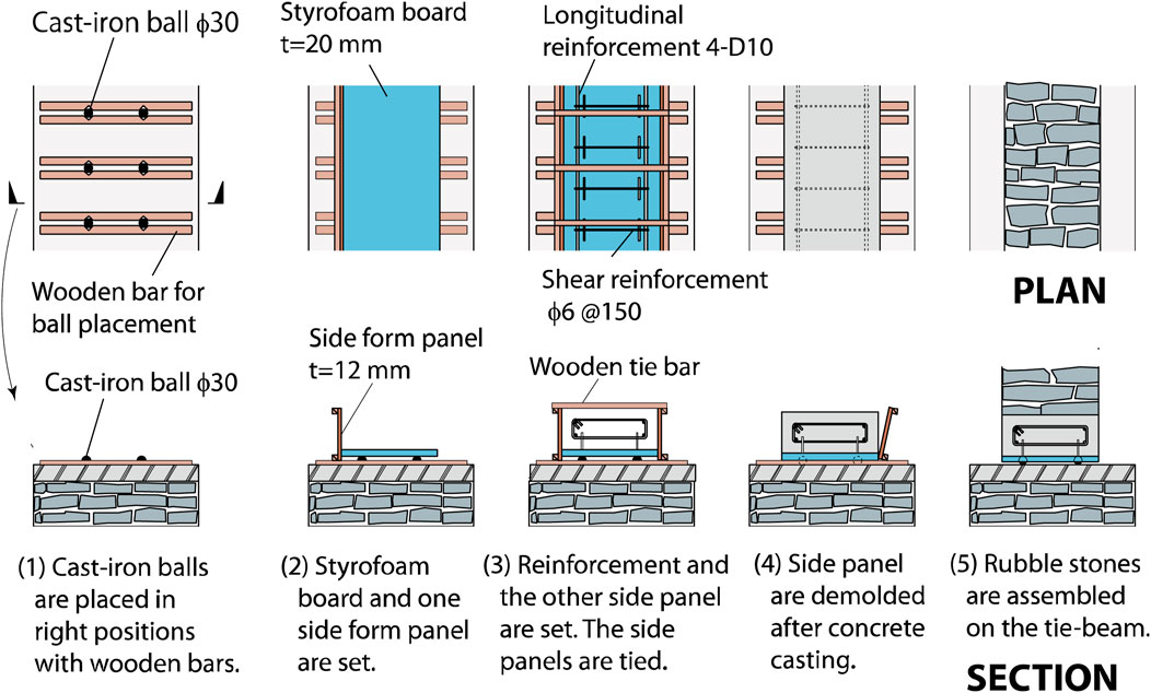
Large beams under and above the isolation layer are not required in the RBIS, because the bearings are continuously placed under the walls. Consequently, changes in the construction procedures from the traditional rubble stone masonry buildings to introduce RBIS are limited. Figure 6 shows the possible sequence of the construction procedure of RBIS.
(1) The cast-iron balls are placed on the foundation slab at the specified locations and pinched with wooden bars so that the balls do not roll.
(2) The styrofoam board is placed on the balls. The board is used as the form panel for the casting concrete of the tie beams. The styrofoam board is not glued to the cast-iron balls.
(3) The reinforcement of the tie beams is assembled and wooden form panels are placed on the sides of tie beams. The panels on the two sides are tightened with wooden bars.
(4) The concrete for tie-beams is cast and cured. The styrofoam board is tightly attached to the tie beams because it is used for the form panel. The balls sink into the styrofoam board with the concrete weight and do not roll. The side form panels and wooden bars are removed.
(5) The masonry walls above the tie beams are constructed. The balls even sink into the styrofoam board during the assembling process of the rubble stones.
Under large earthquakes, the superstructure horizontally moves, while the cast-iron balls roll and horizontally squeeze into the styrofoam boards. Consequently, the induced inertial force on the superstructure during large earthquakes is reduced.
2.3 Application of RBIS to rubble stone masonry buildings
There are multiple reasons why RBIS is suitable for rubble stone masonry buildings in rural areas. Firstly, the residual displacement after large earthquakes is not a primary concern in these buildings because there is no water supply nor any other equipment vertically continuing from the foundation to the superstructure. The masonry buildings with RBIS should be designed such that the maximum displacement during large earthquakes would be small enough for the superstructures to stay on the foundation slabs. However, there is no other building nor obstacle close to the building as shown in Figure 2 so that there is no risk that the superstructures could collide during their horizontal movements under large earthquakes. The limitation of the maximum displacement is not specified; however, 150–200 mm is acceptable with the sufficient width of the lower slab as seen in Figure 2 without the superstructure falling off from the lower slabs. (Relative displacement of 150–200 mm was observed in the shaking table experiment later described in Section 4.4.) Secondly, the system is low-cost with limited additional procedures from the traditional construction of rubble stone masonry buildings. The cast-iron balls are continuously placed under the walls, and the materials needed for RBIS are inexpensive and available in cities nearby. The total volume of these material is relatively small and it is possible to transport them to the building locations in mountainous regions.
The cost increase of introducing RBIS to the school buildings is estimated as being less than approximately 15% of the overall building cost. This number is based on the cost study of the building construction by Schildkamp (Schildkamp and Araki, 2019a) as well as the material and transportation cost derived from our experience creating specimens in experiments and visiting the Himalayan mountainous regions.
The reasons for selecting styrofoam board as the material under the tie beams are listed below:
(a) The styrofoam board is useful both for the embedment of the cast-iron balls and the form panel for casting concrete.
(b) The styrofoam is very light with an approximate specific gravity of 0.02–0.03 and cut by hand easily.
(c) The styrofoam is an inorganic material and it does not decay unlike wood that is a popular construction material. In addition, the material properties do not significantly change under the tie beams without exposure to direct sunlight.
(d) It is reasonably flexible such that the cast-iron balls roll and horizontally squeeze into it during large earthquakes desisting excessive lateral displacement of the superstructures.
3 Quasi-static cyclic loading experiment
3.1 Outline of quasi-static experiment
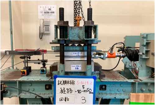
Quasi-static cyclic loading experiments were conducted in order to investigate the performance of RBIS. The specimen is shown in Figure 7A, and the loading facility is shown in Figure 8 and Figure 7B. The materials composing the specimens from the bottom to the top are cast concrete slab (lower slab), four cast-iron balls and precast concrete slab (upper slab) with styrofoam board. The lower slab is a 300 × 300 mm2 with a thickness of 80 mm. The upper slab is 250 × 250 mm2 with a thickness of 50 mm glued to a 20 mm thick styrofoam board. The diameter of the cast-iron balls is 30 mm. The cyclic lateral displacement in the loading schedule shown in Figure 7C was imposed under the constant vertical load. The red and blue lines in the figure indicate the range at which to calculate the rolling coefficients which are described later. The loading velocity was a constant 1.73 mm/s. A single test was defined as the set of displacement loading of three cycles with 50 mm amplitude after one cycle with 10 mm amplitude. The constant vertical load was set as the equivalent load carried by four cast-iron balls in Figure 4.
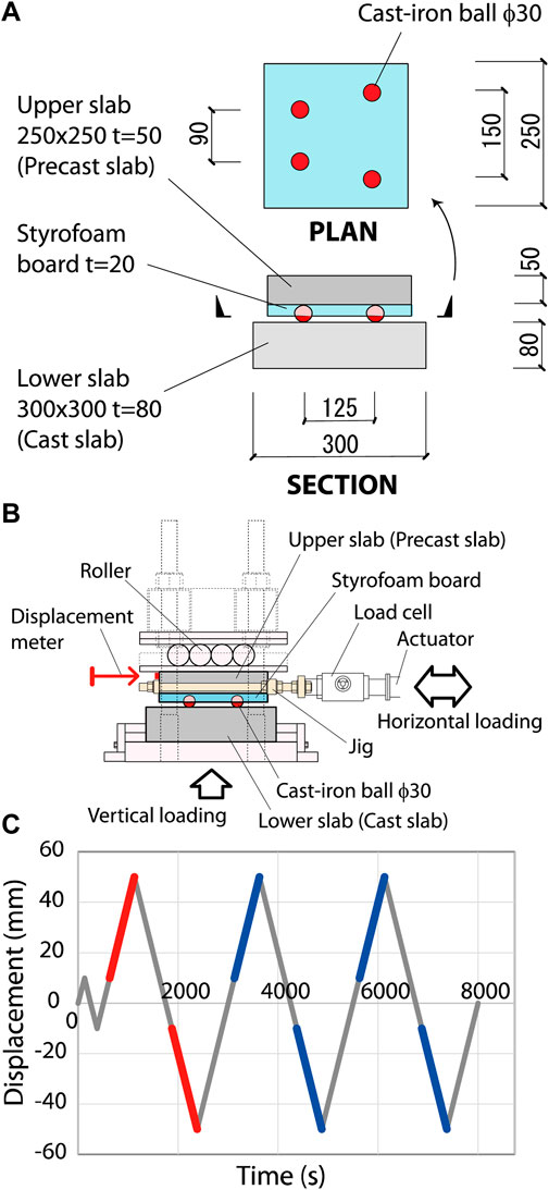
Figure 7. Specimen and loading scheme in quasi-static cyclic loading experiment. (A) Specimen. (B) Loading mechanism. (C) Loading schedule.
The test parameter is the constant vertical loads. The names of the specimen are shown in Table 1. In addition to these three specimens, two more specimens were created and tested. The surface of the lower slab concrete was finished with a wooden piece in one specimen to investigate the influence of the concrete surface conditions, and rusted cast-iron balls were used in the other specimen. These changes did not affect the test results significantly. Therefore, the three specimens listed in Table 1 are discussed below.
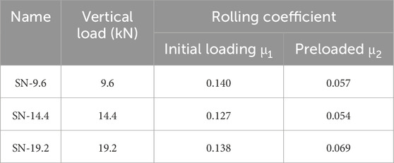
The last numbers in the specimen names in Table 1 indicate the target values of the constant vertical loads (target vertical load) in kN. The vertical loads carried by one cast-iron ball placed at the bottom of walls in Figure 1 in the longitudinal direction with the spacing of 200, 300 and 400 mm are 2.4, 3.6 and 4.8 kN, respectively. The numbers in the specimen names are four times these loads considering the number of cast-iron balls in one specimen (=4). The specimen SN-9.6 is the base, because the most possible spacing of the cast-iron balls is 200 mm. The reasons for conducting the tests with SN-14.4 and SN-19.2 increasing the target vertical loads are to investigate the influence of the vertical load in the RBIS performance and the risk of damages such as cracks in the lower slabs. As discussed later, it was found in the experiments that the influence is limited and no damage was observed. The rolling coefficients in Table 1 are later discussed in Section 3.2.
Concrete mixing is shown in Table 2, and the composition of the cast-iron balls is shown in Table 3. The four-week compressive strength of the mortar is 25.3 N/mm2. The compressive and flexural strength of the styrofoam tested according to JIS K 7220 and JIS K 7221-2 are 0.29 N/mm2 and 1.1 N/mm2, respectively.
3.2 Rolling and slipping
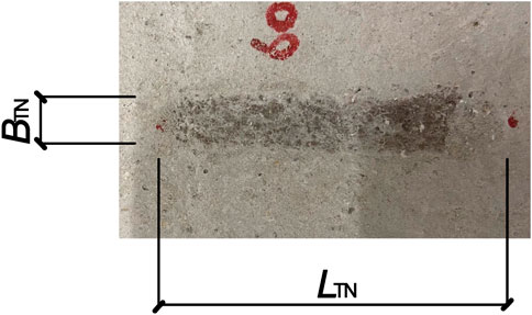
When the upper slab horizontally moves on the lower slab, the cast-iron balls move in two ways, roll and slip. The balls roll horizontally squeezing into the styrofoam, and slip on the surface of the lower slab. During the moving process, these rolling and slipping movements are not clearly separated; however, the rolling is more dominant. The approximate ratio of these movements with respect to the overall lateral movement can be evaluated from the trace on the lower slab. Figure 9 shows the trace on the surface of the lower slab after the third SN-14.4 test. The cast-iron balls make the trace when they roll and slip. There is no clear difference in the trace by rolling and slipping; however, the length of trace is different. The trace length by rolling is half of the relative lateral displacement between the lower and upper slabs, while that by slipping is equal to the relative displacement. Using this fact, the ratio of rolling and slipping movement in the overall lateral movement can be estimated. The abovementioned relationships are expressed in Equations 1, 2.
where
3.3 Relationships between lateral forces and displacements
The relationships between the lateral displacements and F/N in SN-9.6. Are shown in Figure 10. The horizontal axis is the relative lateral displacement between the lower and upper slabs. The vertical axis is F/N, which is the ratio of the resisting lateral force F with respect to the normal force N. The normal force N can be the weight of superstructure mg of the building. In this experiment, N is the vertical load which is the difference between the recorded data from the load-cell connected in series to the actuator and the weight of the lower slab and its base in the facility. During the experiments, the recorded vertical load was not kept constant and changed with the lateral movements due to the performance of the loading facility and changed up to 20%. The plot is colored in yellow, cyan, red and blue with respect to the first to fourth loading cycles in Figure 7C, so that the change of F/N under increasing cycles is clearly observed. The relationships in SN-9.6, SN-14.4 and SN-19.2 are similar and those in SN-9.6 are shown in the figure. No significant difference was observed in these relationships not only in these three specimens, but also in the two tested specimens with rusted cast-iron balls and different surface conditions of lower slab concrete. Four cast-iron balls in each specimen did not carry the vertical force evenly, but it did not affect these relationships. This fact shows the relatively stable RBIS performance with limited influence from the surface conditions of the cast-iron balls and slabs.
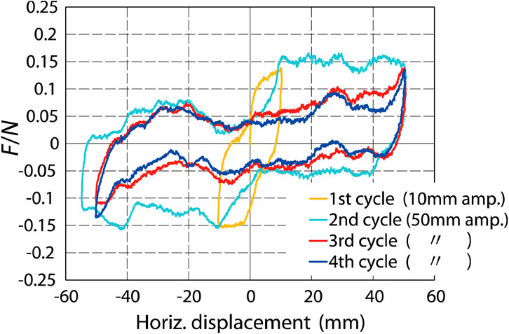
Figure 10. Relationships between F/N and lateral displacement in quasi-static cyclic loading experiments (third SN-9.6 test).
The absolute mean value of F/N corresponding to the red lines in Figure 7C (named the “initial loading displacements”) is denoted as μ1 and, similarly, that corresponding to the blue lines (“preloaded displacements”) is denoted as μ2. μ1 and μ2 are the “rolling coefficients” in the initial loading displacements and preloaded displacements, respectively. The values of F/N are relatively stable when the lateral displacements are greater than 10 mm as seen in Figure 10. It is especially true in the initial loading displacements. The values of μ1 and μ2 are shown in Table 1. The difference between the specimens is relatively small; however, the difference between μ1 and μ2 is large. Specifically, μ1 is around 0.14 and μ2 is around 0.06. The reason for the difference is that the cast-iron balls squeeze into the styrofoam in the initial loading displacements and roll with smaller resistance in the preloaded displacements. The equivalent viscous damping ratio heq is 55% in the initial loading displacements, and is 25% and 19% in the first and second cycle of preloaded displacements, respectively.
3.4 Bearing stress and strength of concrete in lower slab
This section discusses the bearing strength of concrete and the stress under the cast-iron balls. The weight carried by one ball in Figure 4 is 2.4, 3.6 and 4.8 kN in cases of 200, 300 and 400 mm of the ball spacing in the longitudinal direction of the wall, respectively. Assuming that the diameter of the circle where the ball contacts the lower slab is 6 mm, which is the mean value of BTN as shown in Figure 9, the bearing stress is 85, 127 and 170 N/mm2, respectively. The four-week compressive strength of the lower slab is 24 N/mm2. Therefore, the bearing stress with 200 mm spacing is more than three times larger than the compressive strength. The bearing stress under the ball is not uniform and it is not considered. On the other hand, existing research shows that the bearing strength of concrete in a small loading area can be more than three times greater than the compressive strength (Hyland and Chen, 1970). Also, no damage in the lower slab was observed even at the highest bearing stress in the SN-19.2 specimen, where the vertical force corresponds to 400 mm of ball spacing in the buildings. Further investigation regarding the bearing strength and stress may be required; however, this paper continues to discuss the performance of RBIS, mainly focusing on the 200 mm of the ball spacing design.
4 Shaking table experiment
4.1 Outline of shaking table experiment
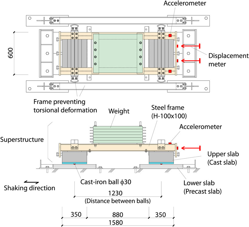
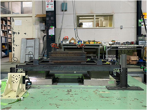
Using the specimen shown in Figure 11, the dynamic behavior of RBIS was investigated in one-directional shaking table experiments (Figure 12). The lower slabs were attached to the shaking table and the superstructure with RBIS was placed on them. Two upper slabs were connected with the steel frame composed of two parallel I-shaped steel beams (H-100 × 100) in the superstructure. The upper slabs were tightened to the frame with bolts, so that the upper slabs could be replaced.
The weights made of steel plates were placed on the steel beams in the middle of the length. The sizes of the upper slab are 600 × 350 mm2 with a thickness of 150 mm. These sizes of thickness and width (=350 mm) are the same as those in the tie beam section in the school buildings in Figure 1. The slabs were created using the styrofoam board as the form panel for the casting concrete so that the building procedure in Figure 6 was examined. The details of the procedure are described later in Section 4.2. Precast concrete slabs with 600 × 300 mm2 with a thickness of 60 mm were used for the lower slabs. Two lower slabs were used for one upper slab. Therefore, four lower slabs in total were used for a single test.
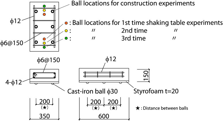
Two cast-iron balls were placed under one upper slab. Therefore, the superstructure was supported by four balls in total. The tilting of an upper slab at about the line between the two balls below is constrained by the two beams in the above steel frame. The combinations of initial locations of cast-iron balls under the upper slab are shown as “Ball locations for shaking table experiments” in Figure 13. Three tests were conducted in one testing case and the initial ball locations were changed in every test, because it was observed in the quasi-static experiments that the rolling coefficients in the initial loading displacements are greater than those in the preloaded displacements.
The test parameters are the weight and input motions. The weight of the superstructure was changed by the steel plates (weight) on the frame. The test case with five steel plates is named SNWKC and that without the plate is named SNLKC. The weight of the superstructure in SNWKC is 9.04 kN including the weight of the upper slabs. The vertical load supported by one cast-iron ball is 2.26 kN (=9.04/4 kN). This load is close to 2.4 kN that is the vertical load on one ball in the rubble stone masonry building in Figure 1 with the 200 mm spacing of the balls in the longitudinal direction of the walls. The weight of the superstructure in SNLKC is 3.14 kN, and the vertical load supported by one ball is 0.79 kN.
4.2 Experiment of upper slab construction
The details of the upper slabs are shown in Figure 13, and their construction procedure is shown in Figure 14. The cast-iron balls and styrofoam are the same as those used in the quasi-static experiments. As shown in Figure 13, there are six balls placed under the upper slab in the construction experiments, simulating the ball placement in the building in Figure 1. On the other hand, there are two balls placed under one upper slab in the shaking table experiments changing the locations, simulating the supporting weight by one cast-iron ball in the building without excessively increasing the weight of the superstructure. The concrete mixing is shown in Table 2. The tested four-week compressive strength is 24.1 N/mm2. The construction procedure of the upper slab is essentially the same as that for the building as shown in Figure 6. The styrofoam was placed on the cast-iron balls which were pinched with wooden bars and the form panels on the sides were nailed on the bar facing the styrofoam without gaps. The side form panels were greased for demolding but the styrofoam was not greased for attaching the styrofoam to the cast concrete.
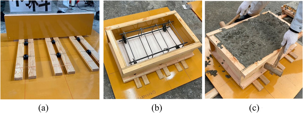
Figure 14. Construction procedure of upper slab. (A) Placement of cast-iron balls. (B) Reinforcement. (C) Casting concrete.
No damage was observed on the styrofoam during the concrete casting. A simple experiment was conducted for investigating the strength of styrofoam by applying loads via the cast-iron balls. The styrofoam did not fail under 10 kN/m2 which is approximately 2.8 times larger than the weight of the tie-beam. The weight of walls above the tie-beams does not load onto the styrofoam once the beam concrete is hardened. Therefore, the styrofoam has sufficient enough strength to serve as the form panel for the tie-beams.
4.3 Input motions and responses
Two input motions were used for the shaking table experiments, which were the sine wave and scaled north-south component of the Imperial Valley Earthquake recorded at El Centro (hereafter referred to as the 1940 El Centro NS). As shown in Figure 15, the sine wave is defined as the constant velocity, 0.4 m/s with increasing acceleration. The constant maximum velocity is controlled by the capacity of the maximum displacement of the shaking table. The recorded El Centro NS motion was scaled so that the maximum velocity is 0.5 m/s. The recorded Gorkha earthquake, which includes the long-period components, was considered for the input motion; however, it was not used because the maximum acceleration is less than 2 m/s2 in the scaled Gorkha motion so that the maximum displacement of the shaking table reaches its capacity. With this small acceleration, the performance of RBIS is not evaluated. The proposed RBIS is developed for reducing the maximum acceleration in short periods and is not effective against long-period ground motions. The buildings applying RBIS are small as shown in Figure 1, and the first natural period is short. Unlike the high-rise buildings, the system is not expected to reduce the response to the long-period ground motions.
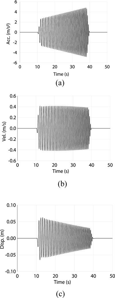
Figure 15. Input sine wave motion in shaking table experiment. (A) Time-acceleration relationship (increasing acceleration up to 4.6 m/s2). (B) Time-velocity relationships (constant velocity of 0.4 m/s). (C) Time-displacement relationship.
Figure 16 shows the recorded accelerations and displacements of SNWKC and SNLKC under the sine wave motions as well as SNWKC under the El Centro motions. The blue lines in the figure show the acceleration of the table and the black lines show that of the superstructure. The recording locations of the displacement and accelerations are shown in Figure 11. The acceleration of the superstructure shown in the figure was low-pass filtered with a cut-off of 10 Hz.
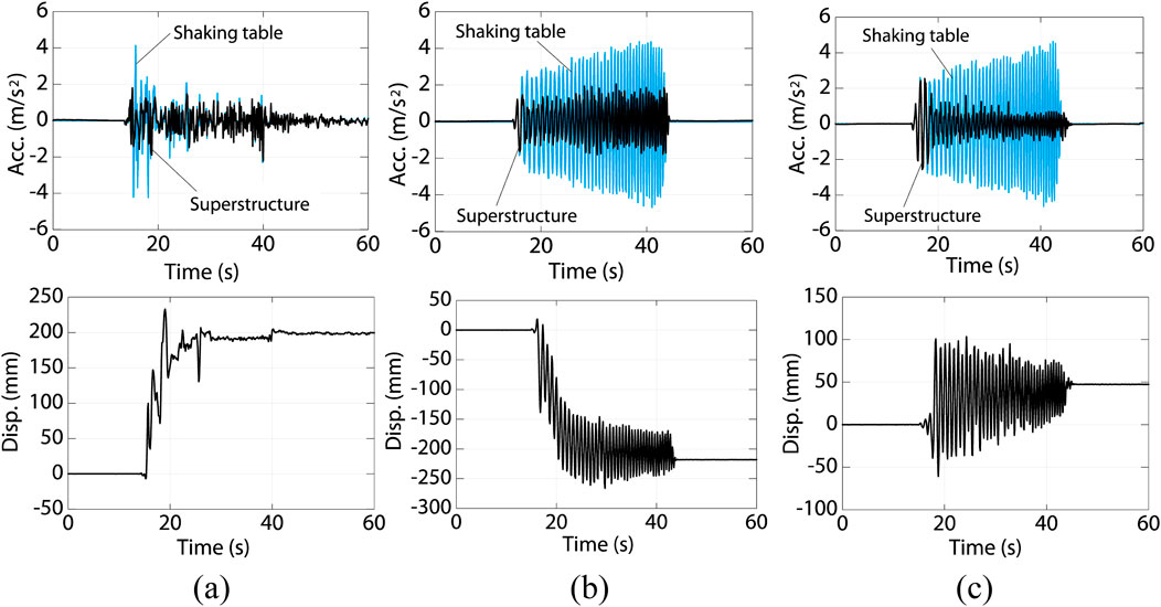
Figure 16. Recorded acceleration and displacement in shaking table experiments. (A) SNWKC El Centro NS. (B) SNWKC sine wave. (C) SNLKC sine wave.
The recorded acceleration on the superstructure is lower than 0.2g. The maximum acceleration remained nearly constant in the heavier specimen, SNWKC, under the sine wave motion with increasing acceleration. As shown in Figure 16A, the maximum response acceleration in El Centro NS motion was also around 0.2g, and its ratio with respect to the maximum acceleration in the input motion is smaller than that in the sine wave motion. On the other hand, the response acceleration in the lighter specimen, SNLKC, is relatively large at around 0.25g as shown in Figure 16C, because the resisting force for the cast-iron balls horizontally bearing onto the styrofoam is relatively large. It was observed in most test cases that the displacements accumulated in one direction. The maximum displacement was around 250 mm. Figure 17 shows the bottom surface of the styrofoam in SNWKC after the test with El Centro NS motion. The traces of the cast-iron balls horizontally squeezing into the styrofoam were confirmed.
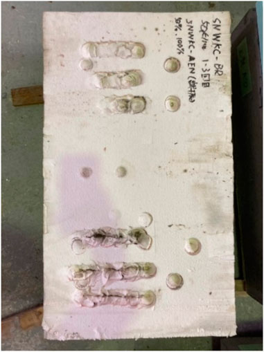
Figure 17. Bottom surface of upper slab after shaking table experiments (SNWKC with El Centro motions).
4.4 Consideration on responses
In the quasi-static cyclic loading experiments described in Chapter 3, it was observed that the rolling coefficients in the initial loading displacements, μ1, and in the preloaded displacements, μ2, are around 0.14 and 0.06, respectively. On the other hand, the maximum response acceleration in the shaking table experiment is around 0.2g, which is greater than the predicted maximum acceleration when taking into account the rolling coefficients, μ1 and μ2. During the experiment, the cast-iron balls horizontally squeezed into the embedded styrofoam. The resisting forces on the balls from the styrofoam are dependent on the relative velocity between the shaking table and specimen. Consequently, the maximum acceleration of the superstructure was greater than that corresponding to the rolling coefficient obtained from the quasi-static experiments.
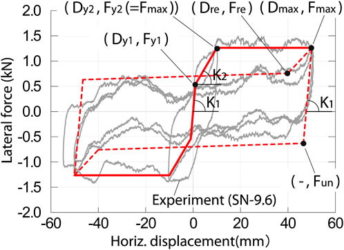
In this section, the shaking table experiment was numerically simulated and the damping ratio was calibrated for evaluation of the velocity-dependent effect. The response history analyses (RHAs) were performed for a single-degree-of-freedom (SDOF) model representing the specimen shown in Figure 11. Figure 18 shows the restoring force relationships of the RBIS of the experiment, superimposed on the relationships between the lateral force and displacement obtained in the SN-9.6 (third test) quasi-static cyclic loading experiments in Figure 10. The restoring force relationships represent the difference of μ1 and μ2, as well as the pinching behavior. The RHAs were performed using the numerical simulation software, OpenSees (Pacific Earthquake Engineering Center (PEER), 2024a). The restoring force relationships are defined in Table 4 by using the Pinching 4 model, which is a material library (Pacific Earthquake Engineering Center (PEER), 2024b) prepared in OpenSees. The relationships are symmetrical with respect to the origin. The symbols for the forces and displacements in Table 4 are shown in Figure 18. The damping ratio h was defined as proportional to the tangent stiffness with respect to the initial natural period. The ratio was calibrated as 6% with the recorded responses in the experiment. The mass of the SDOF model is 0.922 ton (=9.04 kN/g), corresponding to the SNWKC experiment. The Newmark-β method (β = 1/6) was used with the 0.02 s time interval in the numerical integration. Figure 19 compares the accelerations and relative displacements of the tested record in SNWKC El Centro NS and simulation with h = 6% and 0%. As is shown, the simulation under h = 6% reasonably agrees with the recorded responses.
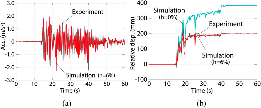
Figure 19. Comparison between recorded responses in shaking table experiments and simulations (SNWKC El Centro NS). (A) Acceleration, (B) Relative displacement.
5 Building behavior under large earthquakes
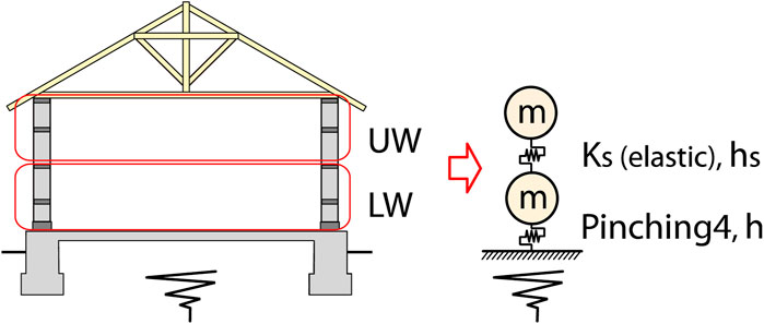
In this section, the seismic response of the school buildings associated with the proposed RBIS is evaluated using the response history analyses (RHAs). The two degrees of freedom (DOF) model shown in Figure 20 was created for the school building in Figure 1. The lower and upper half parts of the walls are modeled as lumped masses, and are named LW and UW, respectively. The roof weight is disregarded because it is significantly small with respect to the wall weight. The masses of LW and UW are the same, denoted as m, which is 72 tons, calculated with 2.0 of the assumed specific gravity of the walls and the volume in the building in Figure 1.
The restoring force characteristics of the RBIS studied in the previous Section 4.4 are used in the analysis model for the building. The first stiffness K1 and second stiffness K2 are given as 86.4 and 12.8 kN/mm, respectively, which are 160 times greater than that used for the experiment as shown in Table 4. The multiplier, 160, is the ratio of the number of cast-iron balls in the building with respect to that in the specimen in Figure 7A (=4). (i.e. Assuming the spacing of the cast-iron balls in the walls in the longitudinal direction is 200 mm, the number of the balls in the building in Figure 1 is approximately 640.) The damping ratio h is 6%, which is the same as that used for the simulation of the experiment in Section 4.4. The first natural period of the superstructure is assumed as 0.1 s referring to the existing experiment (Nanda et al., 2015). The specimen in the experiment is a half scale, single story masonry building and the simple composition is similar to the school building shown in Figure 1. The first natural period of the specimen is reported as 0.04 s. The weight of the full-scale building is 8 times greater, and lateral stiffness is 2 times greater assuming that shear deformation is dominant under lateral forces. Hence, the first natural period of the full-scale structure is estimated as approximately 0.1 s. The lateral stiffness KS between LW and UW is elastic, and calculated as 284 kN/mm with this assumed first natural period. Stiffness proportional damping was imparted as the inherent damping of the superstructure. The damping ratio hS was defined as 5% of the elastic stiffness KS with respect to the first natural period of the superstructure.
In order to evaluate the effect of RBIS, the simulation model for the school buildings constructed in the traditional method was also created. Now, the simulation model for the buildings associated with the proposed RBIS is named the “RBIS model”, and that for the traditional buildings is the “conventional model”. The conventional model is a SDOF model, composed of the upper half of the RBIS model. (i.e., UW is connected to the ground with KS and hS in the conventional model.)
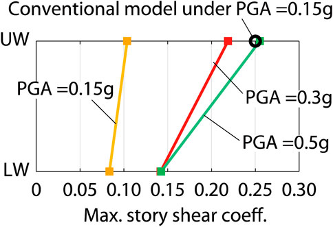
The RHAs were conducted for the RBIS and conventional models using the Newmark-β method. The input ground motions were scaled using El Centro NS (1940) as PGA = 0.15g, 0.3g and 0.5g, respectively. Figure 21 shows the maximum story shear coefficients Cmax, which is defined as the ratio of the maximum shear force with respect to the above weight. Cmax of the conventional model under PGA = 0.15g is 0.25. As discussed in Section 2.1, it is assumed that the traditional rubble stone masonry buildings can resist seismic ground motions with PGA = 0.15g. Therefore, 0.25 can be a threshold of Cmax of the superstructure. Defining such threshold from a single RHA result under a specific recorded ground motion is not sufficient; however, it is focused on here to demonstrate a procedure to evaluate the performance of the proposed system. The threshold (Cmax = 0.25) for UW is superimposed on Figure 21. It shows that Cmax for UW in the RBIS model with PGA = 0.5g is 0.26 and close to the threshold. This can be interpreted as the rubble stone school building associated with RBIS being able to resist the ground motion with PGA = 0.5g. The maximum relative displacement in the isolation layer in RHA with PGA = 0.5g is approximately 180 mm, which can be within the limitation as discussed in Section 2.3.
6 Conclusion
A low-cost rolling base isolation system (RBIS) for rubble stone masonry buildings in the Himalayan mountain range was presented and the feasibility of RBIS in the initial conditions installed in the buildings were evaluated in experiments and simple numerical simulations. The base isolation layer is composed of styrofoam, concrete slab and cast-iron balls. The styrofoam and concrete slab are the upper and lower elements of the isolation layer. The styrofoam boards are used for the embedment of the cast-iron balls and form panels for the casting concrete of the tie beams above the isolation layer. In the case of large earthquakes, these balls roll and horizontally squeeze into the styrofoam boards. The superstructure moves and the induced inertial forces are reduced. The construction procedure of the tie beams was examined and it was confirmed that the styrofoam boards can serve as the form panels with sufficient strength to withstand the concrete weight in the tie beams. The proposed RBIS satisfies two issues for the base isolation system in rubble stone masonry buildings in the Himalayan Mountain range; i.e. (i) use of locally available materials in the isolation layer and (ii) simple construction procedure of the isolation layer by local workers. The quasi-static cyclic loading experiments were conducted. The rolling coefficients of the RBIS were 0.06–0.14. Shaking table experiments were also conducted. It was found that the recorded maximum accelerations are approximately 0.2g. The restoring force characteristics of RBIS in the shaking table experiment were created and the behavior of the experiment was simulated by the response history analyses (RHAs). The damping ratio was defined as 6%, through the calibrations between the responses in the experiment and simulations. Using the created restoring force characteristics and defined damping ratio, the behavior of the rubble stone masonry building associated with RBIS under large earthquakes was evaluated in RHAs. Assuming that the traditional masonry buildings can resist the earthquake ground motions with a PGA under 0.15g, the buildings installed with RBIS can resist the ground motions with a PGA under 0.5g.
Data availability statement
The original contributions presented in the study are included in the article/supplementary material, further inquiries can be directed to the corresponding author.
Author contributions
JT: Conceptualization, Investigation, Methodology, Project administration, Supervision, Visualization, Writing–original draft, Writing–review and editing. TM: Conceptualization, Funding acquisition, Methodology, Project administration, Supervision, Writing–review and editing. YA: Funding acquisition, Investigation, Project administration, Supervision, Writing–review and editing. KI: Conceptualization, Investigation, Methodology, Writing–review and editing. SP: Conceptualization, Investigation, Methodology, Writing–review and editing. SL: Conceptualization, Investigation, Methodology, Writing–review and editing. YS: Conceptualization, Investigation, Methodology, Writing–review and editing. RE: Data curation, Methodology, Writing–review and editing. JG: Data curation, Methodology, Writing–review and editing. KS: Investigation, Methodology, Writing–review and editing. IF: Data curation, Writing–review and editing. HM: Data curation, Visualization, Writing–review and editing.
Funding
The author(s) declare that financial support was received for the research, authorship, and/or publication of this article. This on-site investigation was supported by Grants-in-aid for Scientific Research, Basic Research B (#17H04592), and the quasi-static and shaking table tests were supported by Grants-in-aid for Scientific Research, Fostering Joint International Research B (#20KK0103). The authors are grateful to these financial supports.
Acknowledgments
We gratefully acknowledge the students and former students under our instruction for their assistance in the experiments and numerical simulations: Keigo Yanagihara, Chinami Hirabayashi and Shunsuke Mori at Tokyo Metropolitan University; Naruki Morita, Kazuki Nagamachi and Hiroya Matsuo at Kansai University; and Kotaro Konno, Yuan Shida and Arisa Narumi at Tohoku Gakuin University.
Conflict of interest
The authors declare that the research was conducted in the absence of any commercial or financial relationships that could be construed as a potential conflict of interest.
Publisher’s note
All claims expressed in this article are solely those of the authors and do not necessarily represent those of their affiliated organizations, or those of the publisher, the editors and the reviewers. Any product that may be evaluated in this article, or claim that may be made by its manufacturer, is not guaranteed or endorsed by the publisher.
References
Ali, A., Zhang, C., Bibi, T., Zhu, L., Cao, L., et al. (2022). Investigation of five different low-cost locally available isolation layer materials used in sliding base isolation systems. Soil Dyn. Earthq. Eng. 154, 107127. doi:10.1016/j.soildyn.2021.107127
Ali, Q., Khan, A. N., Ashraf, M., Ahmed, A., Alam, B., Ahmad, N., et al. (2013). Seismic performance of stone masonry buildings used in the himalayan belt. Earthq. Spectra 29 (4), 1159–1181. doi:10.1193/091711eqs228m
Borri, A., Castori, G., Corradi, M., and Speranzini, E. (2012). Shear behavior of unreinforced and reinforced masonry panels subjected to in situ diagonal compression tests. Constr. Build. Mater. 25 (12), 4403–4414. doi:10.1016/j.conbuildmat.2011.01.009
Bothara, J., and Brzev, S. (2011). A tutorial: improving the seismic performance of stone masonry buildings. Oakland, California, USA: Earthquake Engineering Research Institute. Available at: https://www.world-housing.net/tutorials/stone-tutorials (Accessed September 11, 2024).
Foti, D., Goni, A. C., and Vacca, S. (2012). On the dynamic response of rolling base isolation systems. Struct. Control Health Monit. 20 (4), 639–648. doi:10.1002/stc.1538
Galano, S., and Calabrese, A. (2023). State of the art of seismic protection technologies for non-engineered buildings (N-EBs) in developing regions of the world. J. Earthq. Eng. 27 (15), 4327–4353. doi:10.1080/13632469.2023.2165579
Gautam, D., Chettri, N., Tempa, K., Rodrigues, H., and Rupakhety, R. (2022). Seismic vulnerability of Bhutanese vernacular stone masonry buildings: from damage observation to fragility analysis. Soil Dyn. Earthq. Eng. 160, 107351. doi:10.1016/j.soildyn.2022.107351
Goda, K., Kiyota, T., Pokhrel, R. M., Chiaro, G., Katagiri, T., Sharma, K., et al. (2015). The 2015 Gorkha Nepal earthquake: insights from earthquake damage survey. Front. Built Environ. 1, 8. doi:10.3389/fbuil.2015.00008
Hadad, H. A., Calabese, A., Strano, S., and Serino, G. (2017). A base isolation system for developing countries using discarded tyres filled with elastomeric recycled materials. J. Earthq. Eng. 21 (2), 246–266. doi:10.1080/13632469.2016.1172371
Hyland, M. W., and Chen, W. F. (1970). Bearing capacity of concrete blocks. Am. Concr. Inst. J. Proc. 67 (3). doi:10.14359/7264
Katsamakas, A. A., Giudice, L. D., Reyes, S. I., Candebat-Sanchez, D., and Vassiliou, M. F. (2023). Experimental and numerical assessment of grout-filled tennis balls as seismic isolation bearings. Eng. Struct. 294, 116716. doi:10.1016/j.engstruct.2023.116716
Kelly, J. M. (2002). Seismic isolation systems for developing countries. Earthq. Spectra 18 (3), 385–406. doi:10.1193/1.1503339
Khadka, S. S., Acharya, S., Acharya, A., and Veletzos, M. J. (2023). Enhancement of Himalayan irregular stone masonry buildings for resilient seismic design. Front. Built Environ. 9, 1086008. doi:10.3389/fbuil.2023.1086008
Losanno, D., Ravichandran, N., and Parisi, F. (2022). Seismic fragility models for base-isolated unreinforced masonry buildings with fibre-reinforced elastomeric isolators. Earthq. Eng. and Struct. Dyn. 52 (2), 308–334. doi:10.1002/eqe.3761
Losanno, D., Ravichandran, N., Parisi, F., Calabrese, A., and Serino, G. (2021). Seismic performance of a Low-Cost base isolation system for unreinforced brick Masonry buildings in developing countries. Soil Dyn. Earthq. Eng. 141, 106501. doi:10.1016/j.soildyn.2020.106501
Md, Z. N., Mohan, S. C., and Jyosyula, S. K. R. (2023). Development of low-cost base isolation technique using multi-criteria optimization and its application to masonry building. Soil Dyn. Earthq. Eng. 172, 108204. doi:10.1016/j.soildyn.2023.108024
Nanda, R. P., Agarwal, P., and Shrikhande, M. (2012). Suitable friction sliding materials for Base isolation of masonry buildings. Shock Vib. 19, 1327–1339. doi:10.1155/2012/106436
Nanda, R. P., Shrikhande, M., and Agarwal, P. (2015). Low-cost base-isolation system for seismic protection of rural buildings. Am. Soc. Civ. Eng. Pract. Periodical Struct. Des. Constr. 21 (1). doi:10.1061/(ASCE)SC.1943-5576.0000254
Pacific Earthquake Engineering Research Center (PEER), (2024a). Open sees. Available at: https://opensees.berkeley.edu/ (Accessed September 11, 2024).
Pacific Earthquake Engineering Research Center (PEER), (2024b). Pinching4 material. Available at: https://opensees.berkeley.edu/wiki/index.php/Pinching4_Material (Accessed: September 11, 2024).
Parajuli, R. R., Furukawa, A., and Gautamu, D. (2020). Experimental characterization of monumental brick masonry in Nepal. Structures 33, 1314–1321. doi:10.1016/j.istruc.2020.09.065
Qamaruddin, M., Rasheeduzzafar, , Arya, A. S., and Chandra, B. (1986). Seismic response of masonry buildings with sliding substructure. J. Struct. Eng. 112 (9), 2001–2011. doi:10.1061/(asce)0733-9445(1986)112:9(2001)
Sathiparan, N., Mayorca, P., and Meguro, K. (2012). Shake table tests on one-quarter scale models of masonry houses retrofitted with PP-band mesh. Earthq. Spectra 28 (1), 277–299. doi:10.1193/1.3675357
Schildkamp, M., and Araki, Y. (2019a). Cost analysis of mountain schools in Nepal: Comparison of earthquake resistant features in rubble stone masonry vs. Concrete block masonry. Front. Built Environ. 5, 55. doi:10.3389/fbuil.2019.00055
Schildkamp, M., and Araki, Y. (2019b). School buildings in rubble stone masonry with cement mortar in seismic areas: literature review of seismic codes, technical norms and practical manuals. Front. Built Environ. 5, 13. doi:10.3389/fbuil.2019.00013
Schildkamp, M., Silvestri, S., and Araki, Y. (2020). Rubble stone masonry buildings with cement mortar: design specifications in seismic and masonry codes worldwide. Front. Built Environ. 6, 590520. doi:10.3389/fbuil.2020.590520
Schildkamp, M., Silvestri, S., and Araki, Y. (2021). Rubble stone masonry buildings with cement mortar: base shear seismic demand Comparison for selected countries worldwide. Front. Built Environ. 7, 647815. doi:10.3389/fbuil.2021.647815
Shrestha, J. K., Bhandari, S., Pradhan, S., and Gautam, D. (2020). Simplified frame model for capacity assessment of masonry buildings. Soil Dyn. Earthq. Eng. 131, 106056. doi:10.1016/j.soildyn.2020.106056
Suzuki, Y., Tada, M., Enokida, R., Takagi, J., Araki, Y., Pareek, S., et al. (2024). Feasibility of sliding base isolation for rubble stone masonry buildings in the Himalayan Mountain Range. Front. Built Environ. 10. doi:10.3389/fbuil.2024.1432912
Takagi, J., and Wada, A. (2018). Recent earthquakes and the need for a new philosophy for earthquake-resistant design. Soil Dyn. Earthq. Eng. 119, 499–507. doi:10.1016/j.soildyn.2017.11.024
Triantafillou, T. C. (1998). Strengthening of masonry structures using epoxy-bonded FRP laminates. J. Compos. Constr. 2 (2), 96–104. doi:10.1061/(ASCE)1090-0268(1998)2:2(96)
Tsiavos, A., Alexander, N. A., Diambra, A., Ibraim, E., Vardanega, P. J., Gonzalez-Buelga, A., et al. (2019). A sand-rubber deformable granular layer as a low-cost seismic isolation strategy in developing countries: experimental investigation. Soil Dyn. Earthq. Eng. 125, 105731. doi:10.1016/j.soildyn.2019.105731
Tsiavos, A., Sextos, A., Stavridis, A., Dietz, M., Dihoru, L., Di Michele, F., et al. (2021). Low-cost hybrid design of masonry structures for developing countries: shaking table tests. Soil Dyn. Earthq. Eng. 146, 106675. doi:10.1016/j.soildyn.2021.106675
Vecchio, C. D., Natale, A., Caner, A., and Ludovico, M. D. (2022). Experimental and analytical investigation on the lateral response of ball rubber bearing isolators. Soil Dyn. Earthq. Eng. 155, 107157. doi:10.1016/j.soildyn.2022.107157
Wang, M., Liu, K., Lu, H., Shrestha, H., Guragain, R., Pan, W., et al. (2018). In-plane cyclic tests of seismic retrofits of rubble-stone masonry walls. Bull. Earthq. Eng. 16 (5), 1941–1959. doi:10.1007/s10518-017-0262-z
Zhang, C., Ali, A., and Sun, L. (2021). Investigation on low-cost friction-based isolation systems for masonry building structures: experimental and numerical studies. Eng. Struct. 243, 112645. doi:10.1016/j.engstruct.2021.112645
Keywords: rubble stone masonry building, low-cost, seismic isolation, cast iron balls, Shaking table test
Citation: Takagi J, Masui T, Araki Y, Ikago K, Pareek S, Lee S, Suzuki Y, Enokida R, Guo J, Shrestha KC, Fukuda I and Miyagawa H (2024) Development of low-cost rolling base isolation system for seismic protection of rubble stone masonry buildings in Himalayan Mountain range. Front. Built Environ. 10:1495051. doi: 10.3389/fbuil.2024.1495051
Received: 11 September 2024; Accepted: 31 October 2024;
Published: 22 November 2024.
Edited by:
You Dong, Hong Kong Polytechnic University, Hong Kong, SAR ChinaReviewed by:
Mihaela Kouteva-Guentcheva, University of Architecture, Civil Engineering and Geodesy, BulgariaCecilia Rinaldi, Sapienza University of Rome, Italy
Copyright © 2024 Takagi, Masui, Araki, Ikago, Pareek, Lee, Suzuki, Enokida, Guo, Shrestha, Fukuda and Miyagawa. This is an open-access article distributed under the terms of the Creative Commons Attribution License (CC BY). The use, distribution or reproduction in other forums is permitted, provided the original author(s) and the copyright owner(s) are credited and that the original publication in this journal is cited, in accordance with accepted academic practice. No use, distribution or reproduction is permitted which does not comply with these terms.
*Correspondence: Jiro Takagi, anRha2FnaUB0bXUuYWMuanA=
 Jiro Takagi
 Takeshi Masui
 Yoshikazu Araki
 Kohju Ikago
 Sanjay Pareek5
 Sanghun Lee
 Yusuke Suzuki
 Ryuta Enokida
 Jia Guo
 Kshitij C. Shrestha
 Iori Fukuda
 Hayato Miyagawa