 Andreas-Nizar Granitzer
 Haris Felic1
- 1Computational Geotechnics Group, Institute for Soil Mechanics, Foundation Engineering and Computational Geotechnics, Graz University of Technology, Graz, Austria
- 2DB InfraGO AG, Munich, Germany
The design of large-scale pile foundation systems is routinely assisted by finite element simulations. To a large extent, both the modeling and the computational effort of such analyses are governed by the adopted pile modeling technique. The traditional approach to this problem fully resolves the pile and soil domain employing solid elements, resulting in considerable meshing constraints and high simulation runtimes that may be regarded as unbearable for many practical purposes. As an attractive alternative to circumvent these obstacles, embedded FE models have become increasingly popular in solving this modeling task, mainly due to their flexible meshing procedure and significantly enhanced runtime efficiency. In a preceding contribution, the authors have proposed an extended formulation that provides a rigorous framework to capture soil-structure interaction effects at the physical soil-pile contacts. As a key feature, the implemented combined soil-pile coupling scheme explicitly accounts for endpoint interaction. However, validation studies have been constrained to single pile analyses to date. The present work expands this validation scope to large-scale boundary value problems involving multiple piles and investigates the model performance based on three different case studies. The results are compared to both, measurements and numerical benchmark solutions and provide exclusive insight into the numerical fidelity of the developed embedded FE model, with a view to increasing its potential for take-up in engineering practice.
1 Introduction
Pile foundation systems are routinely used for overcoming the challenges of founding large-scale structures, such as high-rise buildings (Tschuchnigg and Schweiger, 2013) or integral bridges (Stastny et al., 2024), in soft soil areas (Poulos and Davis, 1980). Related structures are typically subjected to a combination of vertical, lateral and overturning forces, and have to satisfy limit state requirements concerning their overall stability, serviceability and structural components (DGGT, 2014). A major concern in such analyses is the rigorous treatment of interactions between the structure, the piles and the ground (Hanisch et al., 2002). While simplified design strategies based on empirical or analytical methods remain an integral part in the preliminary design of pile foundation systems, they have an implicit range of applicability that is often disregarded (Sheil et al., 2019); interested readers may refer to Poulos (2010) which highlights pitfalls resulting from an inconvenient selection of related methods.
In comparison, three-dimensional (3D) finite element analyses (FEA) have a relatively higher potential to capture the complex structural behavior of pile foundation systems, particularly in the presence of inhomogeneous soil conditions (Marzouk et al., 2024), non-symmetric geometries (Granitzer et al., 2021) and complex loading paths (Staubach et al., 2023). Nevertheless, in many cases, the use of FEA is limited by the available computational resources for solving boundary value problems (BVPs). In this context, a particularly relevant factor is the pile modeling approach, as it significantly influences the number of degrees of freedom (DOFs) in the underlying system of equations that has to be solved. The standard FE approach (SFEA) to this modeling task incorporates a fully 3D surface-to-surface mesh tying problem between the surfaces of the pile domain (
To circumvent these obstacles inherent to the SFEA, the use of embedded FE models has attracted significant interest in the field of computational geotechnics, particularly for the analysis of bored piles with insignificant soil disturbance caused by pile installation. This concern is underlined by their wide diffusion in commercial finite element (FE) codes, among which ZSoil 3D, RS3, Diana 3D and PLAXIS 3D (Granitzer and Tschuchnigg, 2021). As a key characteristic of embedded FE models,
Building on the seminal works of Ngo and Scodelis (1967) and Phillips and Zienkiewicz (1976) carried out in the field of structural concrete, a number of researchers have contributed to the gradual evolution of embedded FE models for the numerical analysis of geotechnical problems involving piles (Waas and Hartmann, 1984; Kaynia and Kausel, 1991; Sadek and Shahrour, 2004). Subsequent developments over the past two decades have mainly addressed the expansion of the coupling domain (
The remainder of this manuscript is organized as follows: Section 2 concisely recapitulates the relevant theoretical background and visualizes the principal components of the EB-I model introduced by Granitzer et al. (2024d). As a main scientific contribution of this work, sections 3–5 analyze the performance of this formulation considering three different pile foundation systems with varying pile arrangements and loading conditions. These include (i) an idealized 3 × 3 capped pile group subjected to an eccentric vertical load, (ii) a pile-supported integral bridge pier experiencing combined vertical and horizontal loading and (iii) a piled raft foundation with non-symmetric geometry founded on multi-layered ground with inclined soil layer boundaries. Section 6 closes with the conclusions of this work.
2 Background
To render this paper self-contained, this section addresses relevant aspects of the EB-I formulation validated in this work. Full details can be found in Granitzer et al. (2024a), Granitzer et al. (2024c), Granitzer et al. (2024d).
2.1 Embedded beam with implicit interaction surface
Figure 1 illustrates the principal framework of the EB-I proposed by the authors.
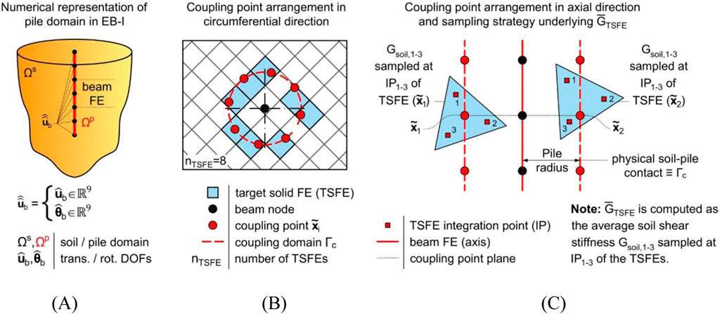
Figure 1. (A) Schematic of pile-soil coupling problem discretized by means of embedded FE model with implicit interaction surface, along with coupling point distribution in (B) circumferential direction of distinct coupling point plane and (C) axial direction, including coupling point embeddings in two different target solid FEs. For clarity, coupling point arrangements are shown for a simplified 2D mesh.
From a mechanical perspective, the EB-I induces a point-wise traction system over
In Equation 1,
where the embedded interface stiffness matrix
In Equation 2,
2.2 Calibration of interface constitutive model parameters
With regard to the embedded interface constitutive relationship described in Equation 2, it should be pointed out that
This lack of reliable methods to determine
2.3 Normal stress recovery methods
To identify the onset of pile-soil slippage, the embedded interface constitutive model formulated within the framework of elastoplasticity employs a Coulomb-type frictional slip criterion, written as:
In Equation 3,
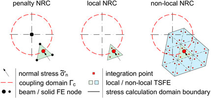
Figure 2. Schematic of normal stress recovery techniques after Granitzer et al. (2024c) described for one EB-I coupling point. For clarity, the stress calculation domains and corresponding coupling variables are shown for a simplified 2D mesh.
Non-local strategies have also found application in the form of strain regularization schemes of strain-softening soil constitutive models, with the aim to compromise the mesh dependency resulting from localized concentrations in the computed field variables (Galavi and Schweiger, 2010; Cui et al., 2023). With reference to the EB-I, a conceptually similar obstacle arises due to the mobilization of multiple discrete traction vectors localized at
3 Capped pile group
This section employs a
3.1 Investigated scenario and model description
The analysis domain dimensions and boundary conditions are adopted from Franza and Sheil (2021). In their work, this reference scenario is used to validate an EB-L formulation under multi-directional loading, notably without providing details about the NRC and calibration of interface constitutive model parameters; cf. Section 2.2 to Section 2.3. Figure 3 shows the foundation geometry that consists of an elevated cap underpinned by a
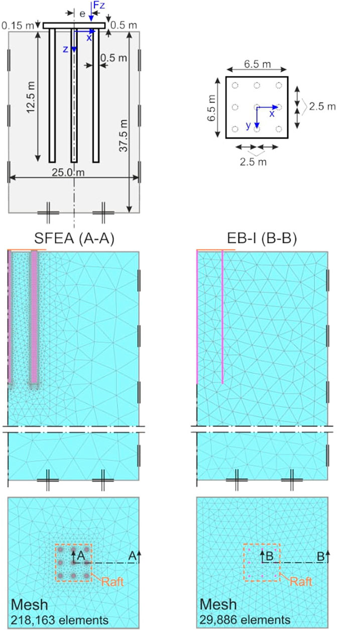
Figure 3. Geometry and load configuration of capped pile group adopted from Franza and Sheil (2021), along with mesh topologies of standard FE approach (SFEA) and EB-I model, respectively.
The rigid cap is modeled as a weightless plate FE and rigidly attached to the piles. It is noticed that the cap is not in contact with the underlying soil. Therefore, the foundation behavior is fully controlled by the pile-soil-pile interaction, which renders this geometrical configuration particularly suitable for EB-I validation purposes. All piles are assumed elastic
In all simulations, the SFEA serves as a benchmark model for numerical validation (Jauregui and Silva, 2011); compare Section 1. Therefore, an additional FE model is generated where the piles are explicitly discretized by means of solid FEs (i.e., representing
The Hardening Soil Small (HSS) soil constitutive parameters (Benz et al., 2009) representing Vienna fine sand are adopted from Tschuchnigg and Schweiger (2010). For simplicity, the influence of groundwater is neglected. The step simulation sequence comprises three principal steps: (i) generation of the initial stress field, (ii) activation of
3.2 Calibration of interface constitutive model parameters
With reference to Section 3.2,
Figure 4A provides insight into the convergence behavior of the automatic calibration, in the form of the relative squared error
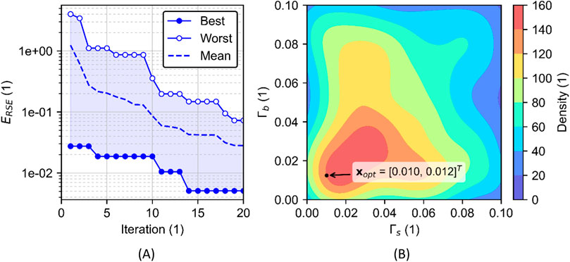
Figure 4. Visualization of (A) the convergence behavior, described as a reduction in the relative squared error (
As a key outcome of the calibration procedure, Figure 5 illustrates the EB-I load-settlement curve obtained with
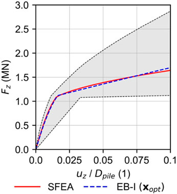
Figure 5. Comparison of load-settlement curves obtained with numerical SFEA benchmark and calibrated EB-I with optimal parameter vector (
3.3 Parametric study
The first set of analyses investigates the effect of eccentric vertical loads on the roto-translational behavior of the capped pile group. Figure 6 displays the normalized settlement
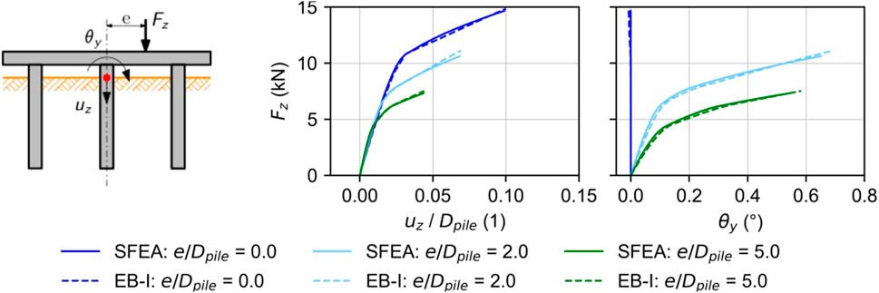
Figure 6. Global response of capped pile group as function of normalized vertical load eccentricity and pile modeling approach.
Figure 7 provides additional insight into the pile model predictions evaluated at the pile head positions. Due to symmetry conditions about the mid-plane (y = 0 m), corresponding piles placed along the upper and lower row of the foundation, respectively, show an identical load-displacement behavior. An interesting detail can be observed for the piles located along the left row of the pile group, where the roto-translational behavior of the pile group leads to pile uplift for
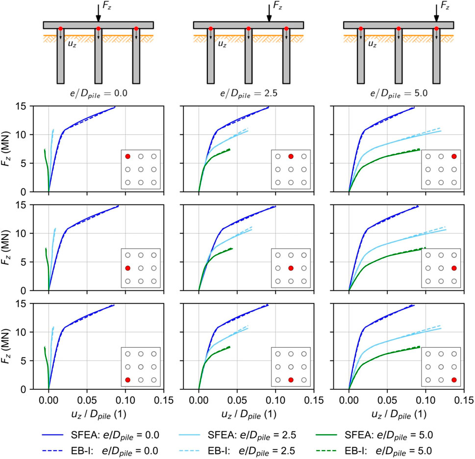
Figure 7. Load-displacement curves as function of the normalized vertical load eccentricity, pile modeling approach and pile position.
4 Pile-supported pier of integral railway bridge
The next section employs an integral bridge case study to examine the EB-I performance under combined vertical and horizontal loading. In addition, it provides guidance in the unit weight selection of EB-Is, an ambiguous material parameter due to the inherent overlapping of the subdomains (that is,
4.1 Case study: integral railway bridge Ems-Jade-Channel
As part of the restructuring of the double-track railway line extending between Oldenburg and Wilhelmshaven in Germany, a new 83-meter-long railway bridge has been constructed over the Ems-Jade canal near Sande. The latter has been designed as three-span composite steel integral bridge, without joints and bearings (see Figure 8), and has been in service since 2021.
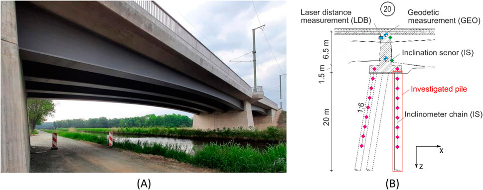
Figure 8. (A) Composite steel integral bridge (Oldenburg – Wilhelmshaven) span between axis 10 and 20 (MKP, 2020); (B) detailed view of the pier monitoring equipment at axis 20.
Before the bridge construction, a comprehensive program of field and laboratory testing has been carried out to evaluate the subsoil conditions (DB ProjektBau GmbH, 2013). Moreover, vertical and horizontal static pile load tests have been conducted to assess the load-displacement behavior of the pier foundation piles and deduce foundation stiffness parameters for the structural model (DB E and C, 2019). The bridge is founded on soft soil deposits with high compressibility and low permeability, comprising a variable mixture of peat, clay, silt and sand to a depth of around 11 m below the ground subsurface. The soft soil alternations are underlain by the load-bearing stratum comprising medium to dense sand. The (partly confined) groundwater table is observed close to the ground surface. To avoid excessive long-term settlements of the railway embankments adjacent to the bridge abutments and to speed up the consolidation process, preloading measures combined with vertical drains have been implemented over a period of several months before the bridge construction. As an additional measure to reduce the settlements to an acceptable limit and ensure the serviceability of the bridge under operating conditions, vertical loads originating from the superstructure and the piers are transferred via large-diameter bored pile groups (
Owing to the rigid connection between the superstructure and the substructure (including abutments, piers and foundations), integral bridges are typically characterized by seasonal lateral deformations induced by the longitudinal thermal expansion of the superstructure (Stastny et al., 2022; Stastny et al., 2024). To this date, however, experimental evidence of thermo-mechanical effects on the structural behavior of integral bridges is rare. To some some extent, this distinct lack of knowledge has motivated the installation of an extensive long-term monitoring system (MKP, 2020). In this respect, Figure 8B provides insight into the monitoring equipment at axis 20. A visual description of the full instrumentation, which has begun operation in November 2021, can be found in Granitzer et al. (2024b). In addition to the recordings related to the composite superstructure, the monitoring focuses on the structural behavior of the substructure components. Essentially, this involves horizontal displacement measurements of (i) selected foundation piles, recorded by means of 14-m-long chain inclinometers, and (ii) relative displacement measurements between the bridge piers at axis 10 and 20 via laser distance measurement (Figure 8B). Subsequently, these results form the basis of the numerical back-analysis and EB-I validation studies.
4.2 Finite element model description
The EB-I is validated by employing a geometrically reduced detail of the integral bridge at axis 20; see Figure 8B. As can be inferred from Figure 9, this includes the pier and the pile foundation system. Numerical back-analyses are conducted considering a quasi-static representation of the horizontal temperature loads related to the expansion of the bridge superstructure. A comparison with both, measurement results and the numerical SFEA benchmark model, for the first time provides insight into the EB-I performance under combined vertical and horizontal loading.
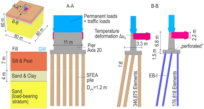
Figure 9. Visual representation of back-analysis domain and boundary conditions for analyzed integral bridge detail at axis 20, along with mesh topology. To provide insight into the SFEA pile discretization, zero-thickness interface elements are not shown.
The soil layering, along with the calibrated Soft Soil (Bentley Systems, 2023) and HSS parameters to describe the soil constitutive behavior of the soft soil alterations and sand layer, respectively, are defined based on the real project data. The calibrated soil constitutive parameter sets have been found suitable for the numerical back-analyses of static pile load tests (DB E and C, 2019). Figure 9 shows the model dimensions and SFEA mesh topology (comprising 346,875 quadratic tetrahedral solid FEs), which are selected based on domain and mesh sensitivity analyses; compare Granitzer and Tschuchnigg (2021). As discussed in Section 1, high mesh refinements around the piles could be circumvented by using EB-Is for the pile modeling, leading to a significantly reduced number of 176,818 solid FEs. Regardless of the pile modeling approach, the piles are assumed elastic
All simulations are conducted utilizing the identical calculation phase sequence. In the initial phase, the initial stress field is generated using the so-called K0 procedure (Bentley Systems, 2023). In this calculation phase, only soil clusters are active and gravity loads are applied. The latter are derived from the soil unit weight and balanced by the effective vertical soil stresses. Next, the piles are wished in place, followed by an activation of the slab and the pier. Subsequently, stage construction effects are considered in the form of Neumann boundary conditions imposed at the top surface of the pier; see Figure 9. The corresponding distributed vertical loads comprise (i) permanent (
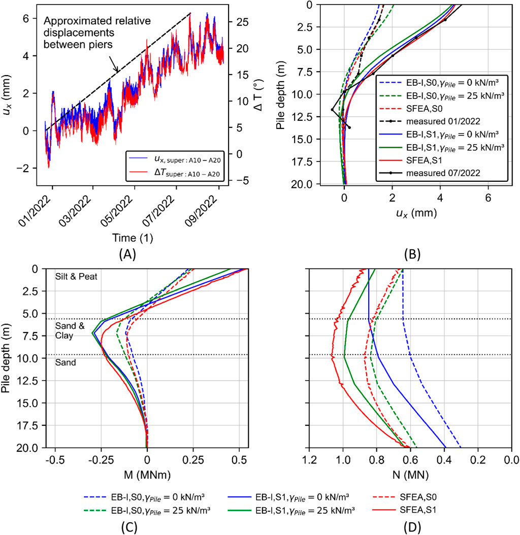
Figure 10. (A) Evolution of horizontal relative displacements
4.3 Back-analysis and parametric study
Although the pile unit weight has a relatively low parameter uncertainty (Mendez et al., 2021) in the FEA of geotechnical problems, the implementational framework of overlay domain decomposition methods (Cai, 2003), such as embedded FE models, renders the underlying parameter selection non-trivial. This rationale is supported by the different approaches reported in the literature, where this parameter is either not documented (Tschuchnigg and Schweiger, 2010; Oliveria and Wong, 2011), defined according to the physical pile unit weight (Tradigo et al., 2016) or assigned with the delta unit weight (Lődör and Balázs, 2018; Watcharasawe et al., 2021), representing the delta unit weight of the pile to the surrounding soil (
To study the relative importance of the selected EB-I unit weight on the credibility of pile predictions, the instrumented pile (Figure 8B) is back-calculated deploying
While the EB-I unit weight has a subordinate importance on the horizontal pile displacements and bending moments, Figure 10D demonstrates that this parameter significantly affects the computed normal force distribution. Apparently, relative differences between the analyzed EB-I configurations increase with increasing pile depth. This observed tendency is not surprising as it can be explained by the influence of the underlying “residual loads” on the pile normal force; cf. Fellenius and Altaee (1995). Essentially, the use of EB-Is with zero-valued pile unit weight considerably underestimates the numerical SFEA benchmark results, whereas it shows reasonable agreement for
5 High-rise building foundation
The third validation exercise studies the EB-I performance employing the 21-storey Franklin Tower. Specifically, this study examines the influence of the NRC on the foundation settlements, simulation runtime and pile skin resistance; compare Section 2.3. Section 5.1 and Section 5.2 briefly describe the project and FE model details, followed by parametric studies presented in Section 5.3.
5.1 Case study: Franklin Tower
Figure 11 shows the around 80-m-high Franklin Tower, which is located adjacent to the Zürich Oerlikon train station. This stepped high-rise building is founded on a piled raft foundation formation, which has a rectangular shape of around 20 × 80 m with partial curvature to the north and is subjected to non-uniformly distributed eccentric loads (Bhartiya et al., 2024). The design of the tower foundation has been assisted by detailed FEA, with the aim to assess the effectiveness of various foundation measures and ensure structural integrity of deformation-sensitive perimeter constructions. The latter include, but are not restricted to, a shopping center with multiple basement levels, a pedestrian underpass and railway tracks. At a depth of about 30 m below the ground level, the Franklin Tower is additionally crossed by a sewer tunnel with a diameter of around 5 m. Interested readers may refer to Granitzer et al. (2024b) for details concerning the governing aspects driving the foundation design.
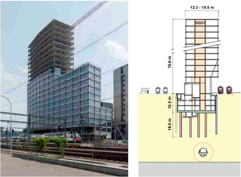
Figure 11. General view of Franklin Tower after completion of structural framework and partial façade installation, along with schematic cross-section (Granitzer et al., 2024b, modified).
The subsoil conditions are characterized by several glacial-interglacial periods, in which basins and valleys of the Alpine region have been filled by lake and riverine sediments (Oberhollenzer et al., 2022). Specifically, the Franklin Tower is founded on alternating layers of fine-grained clayey-silty and silty-sandy soil with a varying degree of overconsolidation; see Figure 12A. A Moraine layer with a constant thickness of around 1.5 m forms the boundary between the fine-grained sediments and the underlying Molasse rock formation. As could be observed from Figure 12B, this Moraine boundary layer extends at a depth of 35–45 m in the project area and has a south-west to north-east descending gradient. This aspect has influenced the tunneling method employed for the sewer tunnel, originally excavated using both, mechanical as well as conventional tunnel driving techniques. The average groundwater level is around 5 m below the terrain, that is, significantly above the excavation base level; see Figure 11B.
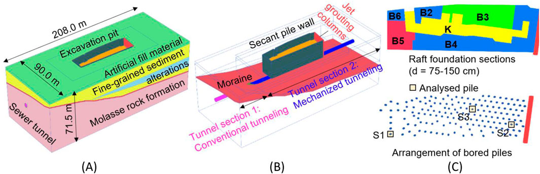
Figure 12. Description of original calculation model “Franklin Tower”: (A) Model configuration and ground model; (B) sewer tunnel, excavation support and moraine layer; (C) pile arrangement layout.
Essentially, Granitzer et al. (2024b) report a satisfactory agreement of the measured (differential) foundation settlements with the original calculation model (Figure 12) involving SFEA piles and around 990,000 quadratic solid FEs. This evidence renders the original calculation model optimal for EB-I validation studies with a particular focus on the relative importance of the NRC; see Section 2.3. Key aspects of the numerical analysis scenario are addressed in the next subsection.
5.2 Finite element model details
Figure 12 shows the structural components, model dimensions and ground stratification of the analysis domain. The lateral excavation support is provided by secant pile walls and jet grouting columns, which are modeled as diaphragm walls with equivalent thickness (
As visually described in Figure 12C, the raft is resting on 170 piles (
5.3 Finite element analysis
Figure 13 depicts the foundation settlement contours obtained with different pile modeling approaches (SFEA, EB-L, EB-I) and NRCs (penalty, local, non-local) in the final loading phase. Due to the varying raft thickness, and for reasons of consistency, the settlements are recovered from the mid-height of distinct raft foundation sections; see Figure 12C.
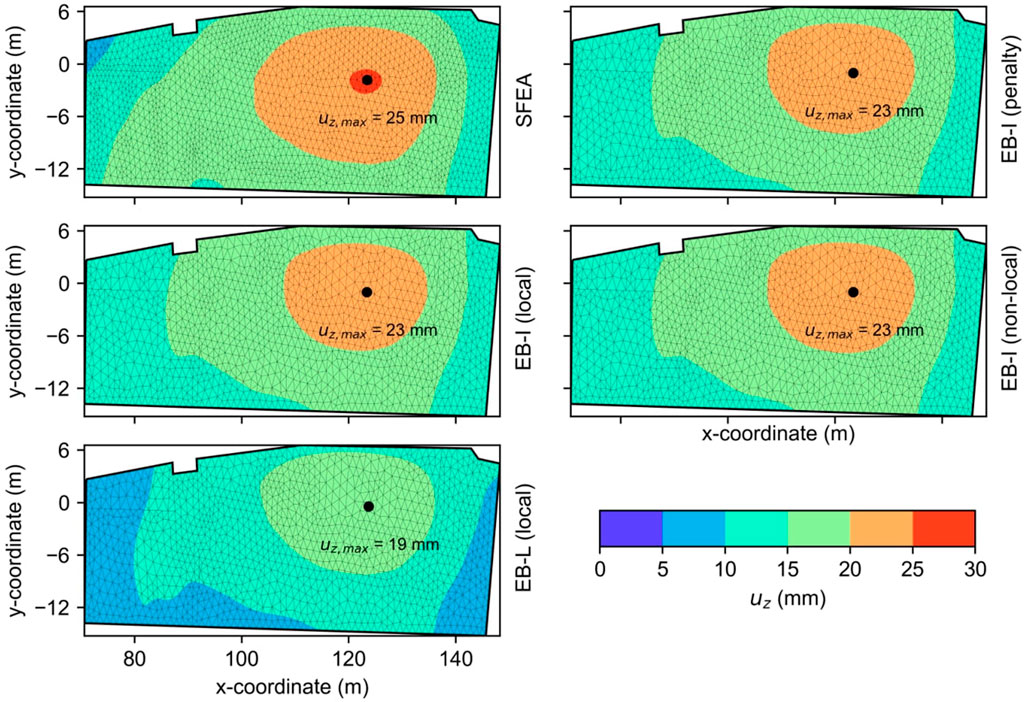
Figure 13. Influence of pile modeling approach and EB-I normal stress recovery technique on foundation settlement contours of the Franklin Tower raft after the final loading phase. The EB-L and EB-I results are presented with respect to the coarse mesh topology.
From the results, it can be inferred that all simulation results are consistent in the sense that the maximum settlements occur close to the raft center beneath raft foundation section B3 and the settlements gradually decrease towards the raft edges. This observation is not surprising, as this section is exposed to the maximum foundation load (
The next study assesses the influence of the pile modeling approach on the computational efficiency, with a particular focus on the NRC. For consistency, all simulations are conducted on a conventional workstation with 64-bit Windows 10 OS, Intel Core i7-7700K 4.2 GHz processor, 32 GB of RAM and a solid-state drive. It is important to notice that the total runtime documented in Table 1 incorporates the setup time for the pre-conditioner as well as the iteration time for solving the system of non-linear equations, and is obtained by running the simulations until the out-of-balance force is less than the default tolerated global error of 1%. The presented speedup ratio is computed as the total runtime of the EB-I and EB-L models, respectively, divided by the total runtime consumed by the original calculation model with SFEA piles.
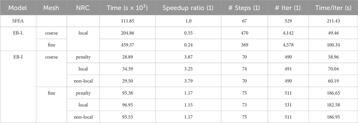
Table 1. Influence of NRC and mesh topology on total consumed runtime.
With reference to the EB-I models, Table 1 indicates a significant decrease in runtime, particularly for the simulations carried out with the coarse mesh. This is manifested in speedup ratios of 3.25 – 3.87. Likewise, this observed tendency is reflected by the significantly reduced normalized runtime per iteration. However, due to the increased number of active DOFs, relative merits in terms of the computational costs are suppressed by employing the fine mesh topology, where the speedup ratios are reduced to 1.15 – 1.17. In all cases, the penalty and non-local NRC achieve slightly improved metrics compared to the local NRC. This tendency qualitatively aligns with the results reported in Granitzer et al. (2024c). Contrary to the EB-I models, the computational efficiency deteriorates in cases where the piles are modeled by means of the EB-L, that is, related speedup ratios (0.24 – 0.55) indicate that the total runtime exceeds those observed with SFEA piles, regardless of the adopted mesh topology. The numerical origin of this anomaly has been delineated based on eigenvalue analyses of the global stiffness matrix (Granitzer et al., 2024d). Specifically, this work demonstrates that an expansion of the interaction domain geometry from an interaction line (EB-L) to an interaction surface (EB-I) results in an improved conditioning of the global stiffness matrix and enhanced convergence rates.
To some extent, the improved numerical robustness associated with the EB-I is reflected in the skin traction profiles shown in Figure 14A. The latter are obtained from three different piles with varying lengths and positions; see Figure 12. Apparently, the EB-L predictions are prone to numerical oscillations, inherently caused by the non-smoothness of the relative displacement field along the interaction line; cf. Granitzer and Tschuchnigg (2023). This numerical obstacle is additionally amplified by the fine mesh (see Figure 14B), which indicates unrealistic negative skin traction values for the S2 pile, as opposed to EB-I predictions. These obstacles are clearly alleviated with the EB-I, which produces skin traction distributions that are relatively independent of the adopted mesh topology and NRC. Moreover, the EB-I has the ability to capture changes in the skin traction distribution induced by the inclined soil layer boundary; cf. Granitzer et al. (2024c). From this perspective, the results indicate that the EB-I can provide first order estimates of the skin traction profiles. Nevertheless, relative differences between the EB-I and the numerical SFEA benchmark close to the pile head (S2) and along limited shaft sections (S1, S3) are evident. To overcome related inconsistencies and enhance numerical fidelity, future EB-I developments could consider expanding the ACF reference data types to explicitly account for the computed skin traction profiles. Moreover, it may be advised to refine the interface constitutive relationship in Equation 2, originally adopted in modified form from Tschuchnigg (2013). However, these aspects are beyond the scope of the present paper and may be addressed in future research.
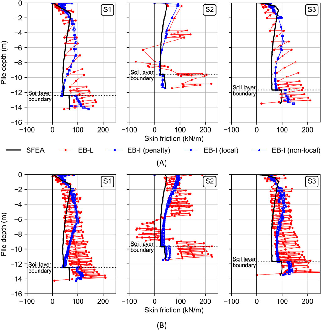
Figure 14. Influence of modeling approach and EB-I normal stress recovery technique on skin traction distribution of three different piles, evaluated with the (A) coarse and (B) fine mesh after final loading.
6 Conclusion
This work has been motivated by the growing demand of finite element formulations for the analysis of large-scale problems involving a high number of pile-type structures that strike a balance between adequate calculation fidelity and acceptable computational expense. Specifically, it extends previous works of the authors (Granitzer et al., 2024c; Granitzer et al., 2024d; Granitzer et al., 2024a), which have focused on the behavior of single piles under axial vertical loads, and for the first time provides insight into the performance of the developed embedded FE model with implicit interaction surface (EB-I) in geotechnical large-scale problems of practical relevance. These include a
• Overall, the EB-I simulations capture the measurements and numerical benchmark predictions in terms of global foundation displacements, pile displacement profiles, bending moment and normal force distributions with high accuracy. Furthermore, it is found that the investigated normal stress recovery techniques produce comparable results. Contrary to previous studies, it should be noted that this numerical evidence is retained from cases with pronounced load eccentricity and combined vertical and horizontal loading.
• The credibility of EB-I predictions is, to some extent, influenced by the selection of the embedded interface constitutive model parameters and the pile unit weight. The former could be successfully calibrated using the automatic calibration framework (ACF) formulated in Granitzer et al. (2024a). The calibrated values documented in this work may serve as a valuable reference in cases where the EB-I simulations are conducted without ACF use. Moreover, it is highlighted that the use of embedded FE models, including the EB-I, leads to overlapping subdomains and requires a careful selection of the associated pile unit weight, which should be determined according to the analysis aims.
• The EB-I proves superior to embedded FE models with implicit interaction line in terms of runtime efficiency and skin traction profiles. In this light, it can be concluded that the EB-I has a relatively higher potential to capture the behavior of piles with insignificant installation effects. Nevertheless, to some extent, the results point out that the predicted skin friction mobilization is yet optimal. To provide more realistic predictions, future research should therefore focus on the formulation of more genuine interface constitutive models and refined contact discretization techniques, such as pioneered by Turello et al. (2017) and Goudarzi and Simone (2019), respectively. Although this work demonstrates the suitability of the developed EB-I for a number of relevant geotechnical application conditions, it should be pointed out that the validation process generally builds on ongoing activities that do not have a clearly defined completion point, as the correctness and accuracy cannot be demonstrated for all possible conditions and applications (Oberkampf et al., 2004); therefore, further understanding of the numerical performance under different application conditions will be instrumental to increase acceptance and move the developed EB-I forward to eventually harness its capabilities in routine practice. This may involve validation studies where the EB-I is employed for the modelling of pile anchors (Zheng et al., 2024b), retaining walls formed by rotating vertical piles (Zheng et al., 2024a), or the parametric analysis of deep foundations near slopes (Zhou et al., 2024).
Data availability statement
The raw data supporting the conclusions of this article will be made available by the authors, without undue reservation.
Author contributions
A-NG: Conceptualization, Methodology, Project administration, Software, Validation, Visualization, Writing–original draft. HF: Validation, Visualization, Writing–review and editing. JL: Validation, Visualization, Writing–review and editing. AS: Formal Analysis, Visualization, Writing–review and editing. FT: Supervision, Writing–review and editing.
Funding
The author(s) declare that no financial support was received for the research, authorship, and/or publication of this article.
Acknowledgments
The authors wish to thank Sven Kromminga, Max Käding and Marc Wenner from Marx Krontal Partner GmbH for providing the measurement data and figures concerning the integral bridge case study. The support provided by dsp Ingenieur + Planer AG and Christian Baudet with respect to the Franklin Tower case study is greatly acknowledged. We gratefully acknowledge the finicial support from the TU Graz Open Access Publishing Fund for providing the open access funding.
Conflict of interest
Author AS was employed by the company DB InfraGO AG.
The remaining authors declare that the research was conducted in the absence of any commercial or financial relationships that could be construed as a potential conflict of interest.
Publisher’s note
All claims expressed in this article are solely those of the authors and do not necessarily represent those of their affiliated organizations, or those of the publisher, the editors and the reviewers. Any product that may be evaluated in this article, or claim that may be made by its manufacturer, is not guaranteed or endorsed by the publisher.
References
Abu-Farsakh, M., Souri, A., Voyiadjis, G., and Rosti, F. (2018). Comparison of static lateral behavior of three pile group configurations using three-dimensional finite element modeling. Can. Geotech. J. 55, 107–118. doi:10.1139/cgj-2017-0077
Benz, T., Schwab, R., and Vermeer, P. (2009). Small-strain stiffness in geotechnical analyses. Bautechnik 86, 16–27. doi:10.1002/bate.200910038
Bhartiya, P., Basu, D., and Chakraborty, T. (2024). Behavior of piled rafts in sand under nonuniform and eccentric loads. Acta Geotech. 19, 5315–5336. doi:10.1007/s11440-024-02247-6
Cai, X. (2003). “Overlapping domain decomposition methods,” in Advanced topics in computational partial differential equations. Editors T. J. Barth, M. Griebel, D. E. Keyes, R. M. Nieminen, D. Roose, and T. Schlick (Berlin: Springer), 57–95.
CEN (2003). Eurocode 1: actions on structures - Part 2: traffic loads on bridges. EN 1991-2:2003. Brussels: European Committee for Standardization.
Cui, W., Wu, X., Potts, D. M., and Zdravković, L. (2023). Nonlocal strain regularisation for critical state models with volumetric hardening. Comput. Geotechnics 157, 105350. doi:10.1016/j.compgeo.2023.105350
Day, R. A., and Potts, D. M. (1994). Zero thickness interface elements—numerical stability and application. Int. J. Numer. Anal. Meth. Geomech. 18, 689–708. doi:10.1002/nag.1610181003
DB E and C (2019). EÜ Ems-Jade-Channel: internal report concerning numerical simulations of static pile load tests. Hannover.
Di Laora, R., Sanctis, L. D., and Aversa, S. (2019). Bearing capacity of pile groups under vertical eccentric load. Acta Geotech. 14, 193–205. doi:10.1007/s11440-018-0646-5
Di Prisco, C., Flessati, L., and Porta, D. (2020). Deep tunnel fronts in cohesive soils under undrained conditions: a displacement-based approach for the design of fibreglass reinforcements. Acta Geotech. 15, 1013–1030. doi:10.1007/s11440-019-00840-8
Engin, H., Brinkgreve, R., and Septanika, E. (2007). “Improved embedded beam elements for the modelling of piles,” in Numerical models in geomechanics: proceedings of the 10th international symposium on numerical models in geomechanics. Editor G. N. Pande (London: Taylor and Francis), 475–480.
Fellenius, B. H., and Altaee, A. (1995). Critical Depth: how it came into being and why it does not exist. Geotech. Eng. 113, 107–111. doi:10.1680/igeng.1995.27590
Franza, A., and Marshall, A. M. (2019). Centrifuge and real-time hybrid testing of tunneling beneath piles and piled buildings. J. Geotechnical Geoenvironmental Eng. 145, 1–10. doi:10.1061/(ASCE)GT.1943-5606.0002003
Franza, A., and Sheil, B. (2021). Pile groups under vertical and inclined eccentric loads: elastoplastic modelling for performance based design. Comput. Geotechnics 135, 104092. doi:10.1016/j.compgeo.2021.104092
Galavi, V., and Schweiger, H. F. (2010). Nonlocal multilaminate model for strain softening analysis. Int. J. Geomech. 10, 30–44. doi:10.1061/(ASCE)1532-3641(2010)10:1(30)
Ghofrani, A. (2018). Development of numerical tools for the evaluation of pile response to laterally spreading soil. Washington DC: University of Washington. Dissertation.
Goudarzi, M., and Simone, A. (2019). Discrete inclusion models for reinforced composites: comparative performance analysis and modeling challenges. Comput. Methods Appl. Mech. Eng. 355, 535–557. doi:10.1016/j.cma.2019.06.026
Granitzer, A., Tschuchnigg, F., Summerer, W., Galler, R., and Stoxreiter, T. (2021). Errichtung eines Eisenbahntunnels in Deckelbauweise über dem Hauptsammler West der Stadt Stuttgart/Construction of a railway tunnel above the main drainage tunnel of Stuttgart using the cut-and-cover method. Bauingenieur 96, 156–164. doi:10.37544/0005-6650-2021-05-40
Granitzer, A.-N., Leo, J., and Tschuchnigg, F. (2024a). Particle Swarm optimization of interface constitutive model parameters for embedded beam formulations. Int. J. Geomech. 24. in press. doi:10.1061/IJGNAI/GMENG-9429
Granitzer, A.-N., Stastny, A., Felic, H., Leo, J., Buss, C., and Tschuchnigg, F. (2024b). “Einfluss der Pfahlmodellierung bei FE-Analysen am Beispiel von zwei komplexen Großprojekten,” in 14th Austrian geotechnical conference and vienna-terzaghi-lecture: proceedings. Editors D. Adam, and A. Hausenberger (Vienna: ÖIAV), 313–324.
Granitzer, A.-N., and Tschuchnigg, F. (2021). Practice-oriented validation of embedded beam formulations in geotechnical engineering. Processes 9, 1739–39. doi:10.3390/pr9101739
Granitzer, A.-N., and Tschuchnigg, F. (2023). “Finite element formulations for implicit beam-to-solid coupling: numerical obstacles and solution strategies,” in 10th European conference on numerical methods in geotechnical engineering (NUMGE 2023): proceedings. Editors L. Zdravkovic, A. Tsiampousi, D. Taborda, and S. Kontoe (Boca Raton: CRC Press), 1–6.
Granitzer, A.-N., Tschuchnigg, F., Felic, H., Bonnier, P., and Brasile, S. (2024c). Implementation and appraisal of stress recovery techniques for embedded finite elements with frictional contact. Comput. Geotechnics 172, 106457. doi:10.1016/j.compgeo.2024.106457
Granitzer, A.-N., Tschuchnigg, F., Hosseini, S., and Brasile, S. (2024d). Insight into numerical characteristics of embedded finite elements for pile-type structures employing an enhanced formulation. Int. J. Numer. Anal. Meth. Geomech. 48, 223–249. doi:10.1002/nag.3641
Hanisch, J., Katzenbach, R., and König, G. (2002). Kombinierte pfahl-plattengründungen. Berlin: Ernst and Sohn.
He, R., and Kaynia, A. M. (2024). Winkler spring coefficients for laterally loaded piles. Comput. Geotechnics 170, 106264. doi:10.1016/j.compgeo.2024.106264
Helwig, S. (2010). Particle swarms for constrained optimization. Nuremberg: University of Erlangen–Nuremberg. Dissertation.
Jauregui, R., and Silva, F. (2011). “Numerical validation methods,” in Numerical analysis - theory and application. Editor J. Awrejcewicz (London: InTech Open), 155–174.
Jürgens, H., Vogel, P., Henke, S., and Grabe, J. (2022). Zur numerischen Berechnung der globalen Standsicherheit von Bauwerken im Boden. Geotechnik 45, 155–169. doi:10.1002/gete.202200003
Kaynia, A. M., and Kausel, E. (1991). Dynamics of piles and pile groups in layered soil media. Soil Dyn. Earthq. Eng. 10, 386–401. doi:10.1016/0267-7261(91)90053-3
Kishida, H., and Meyerhof, G. G. (1966). “Bearing capacity of pile groups under eccentric loads in sand,” in Proceedings of the 6th international conference on soil mechanics and foundation engineering. Editor R. F. Legget (Toronto: University of Toronto Press), 270–274.
Lődör, K., and Balázs, M. (2018). “Finite element modelling of rigid inclusion ground improvement,” in Numerical methods in geotechnical engineering: proceedings of the 9th European conference on numerical methods in geotechnical engineering. Editors A. S. Cardoso, J. L. Borges, P. A. Costa, A. T. Gomes, J. C. Marques, and C. S. Vieira (London: CRC Press), 1399–1406.
Marzouk, I., Granitzer, A.-N., Rauter, S., and Tschuchnigg, F. (2024). A case study on advanced CPT data interpretation: from stratification to soil parameters. Geotech. Geol. Eng. 42, 4087–4113. doi:10.1007/s10706-024-02774-9
Mendez, F. J., Pasculli, A., Mendez, M. A., and Sciarra, N. (2021). Calibration of a hypoplastic model using genetic algorithms. Acta Geotech. 16, 2031–2047. doi:10.1007/s11440-020-01135-z
Meyerhof, G. G., Yalcin, A. S., and Mathur, S. K. (1983). Ultimate pile capacity for eccentric inclined load. J. Geotechnical Eng. 109, 408–423. doi:10.1061/(ASCE)0733-9410(1983)109:3(408)
MKP (2020). EÜ Ems-Jade-Channel: measurement concept and continuous technical monitoring: Marx krontal partner GmbH. Weimar.
Ngo, D., and Scodelis, A. C. (1967). Finite element analysis of reinforced concrete beams. ACI J. 64, 152–163. doi:10.14359/7551
Ninić, J., Stascheit, J., and Meschke, G. (2014). Beam-solid contact formulation for finite element analysis of pile-soil interaction with arbitrary discretization. Num Anal. Meth Geomech. 38, 1453–1476. doi:10.1002/nag.2262
Oberhollenzer, S., Baldermann, A., Marte, R., Tahir, D. M. M., Tschuchnigg, F., Dietzel, M., et al. (2022). Microstructure development in artificially cemented, fine-grained soils. Geosciences 12, 333–417. doi:10.3390/geosciences12090333
Oberkampf, W. L., Trucano, T. G., and Hirsch, C. (2004). Verification, validation, and predictive capability in computational engineering and physics. Appl. Mech. Rev. 57, 345–384. doi:10.1115/1.1767847
Öchsner, A., and Merkel, M. (2018). One-dimensional finite elements: an introduction to the FE method. Basel: Springer Cham.
Oliveria, D., and Wong, P. K. (2011). Use of embedded pile elements in 3D modelling of piled-raft foundations. Aust. Geomechanics J. 46, 9–19.
Phillips, D. V., and Zienkiewicz, O. C. (1976). Finite element non-linear analysis of concrete structures. Proc. Institution Civ. Eng. 61, 59–88. doi:10.1680/iicep.1976.3503
Poulos, H. G. (2010). “High-rise building foundations—a limit state design approach,” in Art of foundation engineering practice. Editor M. H. Hussein (Reston: ASCE), 501–516.
Poulos, H. G., and Davis, E. H. (1980). Pile foundation and design. New Jersey: John Wiley and Sons Inc.
Rajapakse, R. K. N. D. (1990). Response of an axially loaded elastic pile in a Gibson soil. Géotechnique 40, 237–249. doi:10.1680/geot.1990.40.2.237
Randolph, M. F., and Wroth, C. P. (1979). An analysis of the vertical deformation of pile groups. Géotechnique 29, 423–439. doi:10.1680/geot.1979.29.4.423
Sadek, M., and Shahrour, I. (2004). A three dimensional embedded beam element for reinforced geomaterials. Num Anal. Meth Geomech. 28, 931–946. doi:10.1002/nag.357
Schweiger, H. F., Tschuchnigg, F., and Oberhollenzer, S. (2018). Franklin turm - Zürich: final project report. Graz: Graz University of Technology.
Sheil, B. B., and McCabe, B. A. (2016). An analytical approach for the prediction of single pile and pile group behaviour in clay. Comput. Geotechnics 75, 145–158. doi:10.1016/j.compgeo.2016.02.001
Sheil, B. B., McCabe, B. A., Comodromos, E. M., and Lehane, B. M. (2019). Pile groups under axial loading: an appraisal of simplified non-linear prediction models. Géotechnique 69, 565–579. doi:10.1680/jgeot.17.r.040
Smulders, C. M., Hosseini, S., and Brinkgreve, R. (2019). “Improved embedded beam with interaction surface,” in Proceedings of the 17th European conference on soil mechanics and geotechnical engineering. Editors H. Sigursteinsson, S. Erlingsson, and B. Bessason (Reykjavík: COC), 1048–1055.
Stastny, A., Knittel, L., Meier, T., and Tschuchnigg, F. (2024). Experimental determination of hypoplastic parameters and cyclic numerical analysis for railway bridge backfills. Acta Geotech. doi:10.1007/s11440-024-02312-0
Stastny, A., Stein, R., and Tschuchnigg, F. (2022). “Long-term monitoring of the transition zone of an integral railway bridge in Germany,” in Field measurements in geomechanics, 1–7. ISSMGE TC220.
Staubach, P., Machaček, J., and Wichtmann, T. (2022). Novel approach to apply existing constitutive soil models to the modelling of interfaces. Int. J. Numer. Anal. Meth. Geomech. 46, 1241–1271. doi:10.1002/nag.3344
Staubach, P., Tschirschky, L., Machaček, J., and Wichtmann, T. (2023). Monopile installation in clay and subsequent response to millions of lateral load cycles. Comput. Geotechnics 155, 105221. doi:10.1016/j.compgeo.2022.105221
Steinbrecher, I., Hagmeyer, N., Meier, C., and Popp, A. (2022a). A consistent mixed-dimensional coupling approach for 1D Cosserat beams and 2D solid surfaces. Preprint, submitted October 28, 2022. doi:10.48550/arXiv.2210.16010
Steinbrecher, I., Mayr, M., Grill, M. J., Kremheller, J., Meier, C., and Popp, A. (2020). A mortar-type finite element approach for embedding 1D beams into 3D solid volumes. Comput. Mech. 66, 1377–1398. doi:10.1007/s00466-020-01907-0
Steinbrecher, I., Popp, A., and Meier, C. (2022b). Consistent coupling of positions and rotations for embedding 1D Cosserat beams into 3D solid volumes. Comput. Mech. 69, 701–732. doi:10.1007/s00466-021-02111-4
Stewart, J. F., and Kulhawy, F. H. (1981). “Interpretation of uplift load distribution data,” in Proceedings of the 10th international conference on soil mechanics and foundation engineering (Stockholm: A.A. Balkema), 277–280.
Tradigo, F., Pisanò, F., and Di Prisco, C. (2016). On the use of embedded pile elements for the numerical analysis of disconnected piled rafts. Comput. Geotechnics 72, 89–99. doi:10.1016/j.compgeo.2015.11.005
Trochanis, A. M., Bielak, J., and Christiano, P. (1991). Three-dimensional nonlinear study of piles. J. Geotechnical Eng. 117, 429–447. doi:10.1061/(ASCE)0733-9410(1991)117:3(429)
Truty, A. (2023). Nonlocal FEM modeling of piles as beam elements embedded within 3D continuum. Eng. Struct. 277, 115460. doi:10.1016/j.engstruct.2022.115460
Tschuchnigg, F. (2013). 3D finite element modelling of deep foundations employing an embedded pile formulation. Graz: Graz University of Technology.
Tschuchnigg, F., and Schweiger, H. F. (2010). “Study of a complex deep foundation system using 3D Finite Element analysis,” in Numerical methods in geotechnical engineering: proceedings of the seventh European conference on numerical methods in geotechnical engineering, trondheim, Norway, 2-4 june 2010. Editors S. Nordal, and T. Benz (Leiden: CRC Press), 40–46.
Tschuchnigg, F., and Schweiger, H. F. (2013). Comparison of deep foundation systems using 3D finite element analysis employing different modeling techniques. Geotech. Eng. 44, 40–46.
Tschuchnigg, F., and Schweiger, H. F. (2015). The embedded pile concept – verification of an efficient tool for modelling complex deep foundations. Comput. Geotechnics 63, 244–254. doi:10.1016/j.compgeo.2014.09.008
Turello, D. F., Pinto, F., and Sánchez, P. J. (2016). Embedded beam element with interaction surface for lateral loading of piles. Num Anal. Meth Geomech. 40, 568–582. doi:10.1002/nag.2416
Turello, D. F., Pinto, F., and Sánchez, P. J. (2017). Three dimensional elasto-plastic interface for embedded beam elements with interaction surface for the analysis of lateral loading of piles. Num Anal. Meth Geomech. 41, 859–879. doi:10.1002/nag.2633
Turello, D. F., Pinto, F., and Sánchez, P. J. (2019). Analysis of lateral loading of pile groups using embedded beam elements with interaction surface. Num Anal. Meth Geomech. 43, 272–292. doi:10.1002/nag.2863
Waas, G., and Hartmann, H. G. (1984). “Seismic analysis of pile foundations including pile-soil-pile interaction,” in Proceedings of the 8th world conference on earthquake engineering, EERI (Englewood Cliffs: Prentice-Hall), 55–62.
Watcharasawe, K., Jongpradist, P., Kitiyodom, P., and Matsumoto, T. (2021). Measurements and analysis of load sharing between piles and raft in a pile foundation in clay. Geomechanics Eng. 24, 559–572. doi:10.12989/GAE.2021.24.6.559
Williamson, M. G., Mair, R. J., Devriendt, M. D., and Elshafie, M. Z. E. B. (2017). Open-face tunnelling effects on non-displacement piles in clay – part 2: tunnelling beneath loaded piles and analytical modelling. Géotechnique 67, 1001–1019. doi:10.1680/jgeot.SIP17.P.120
Zdravkovic, L., Potts, D. M., and St John, H. D. (2005). Modelling of a 3D excavation in finite element analysis. Géotechnique 55, 497–513. doi:10.1680/geot.2005.55.7.497
Zheng, G., Guo, Z., Zhou, H., and He, X. (2024a). Design method for wall deformation and soil movement of excavations with inclined retaining walls in sand. Int. J. Geomech. 24. doi:10.1061/IJGNAI.GMENG-9029
Zheng, G., Guo, Z., Zhou, H., Tan, Y., Wang, Z., and Li, S. (2024b). Multibench-retained excavations with inclined–vertical framed retaining walls in soft soils: observations and numerical investigation. J. Geotechnical Geoenvironmental Eng. 150. doi:10.1061/JGGEFK.GTENG-11943
Zhou, H., Zhang, J., Yu, X., Hu, Q., Zheng, G., Xu, H., et al. (2024). Stochastic bearing capacity and failure mechanism of footings placed adjacent to slopes considering the anisotropic spatial variability of the clay undrained strength. Int. J. Geomech. 24. doi:10.1061/IJGNAI.GMENG-9136
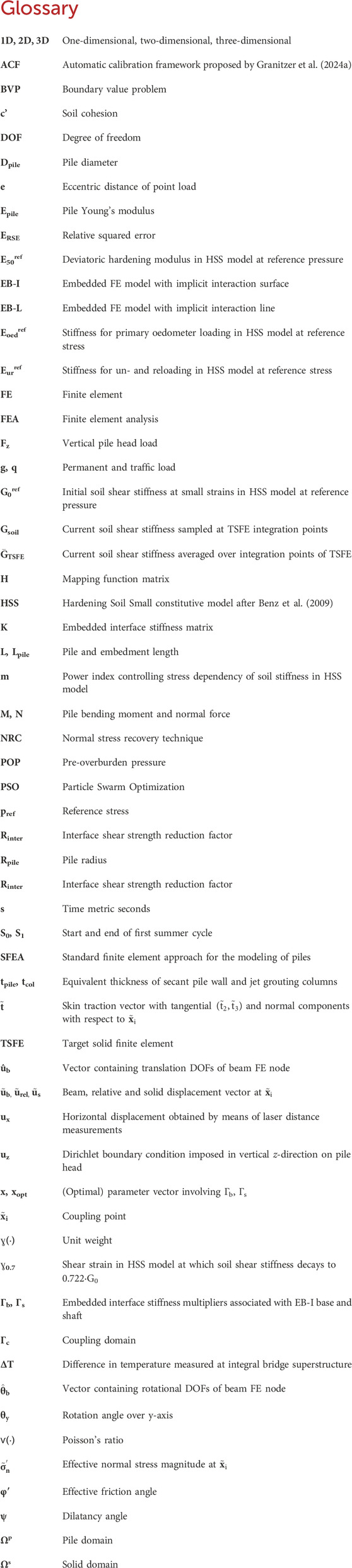
Glossary
Keywords: embedded finite element, pile, foundation, integral bridge, high-rise building
Citation: Granitzer A-N, Felic H, Leo J, Stastny A and Tschuchnigg F (2024) Numerical investigation of pile foundation systems employing an enhanced embedded finite element. Front. Built Environ. 10:1454266. doi: 10.3389/fbuil.2024.1454266
Received: 24 June 2024; Accepted: 09 September 2024;
Published: 25 September 2024.
Edited by:
Hoang Bao Khoi Nguyen, University of South Australia, AustraliaReviewed by:
Christos Vrettos, University of Kaiserslautern, GermanyHaizuo Zhou, Tianjin University, China
Copyright © 2024 Granitzer, Felic, Leo, Stastny and Tschuchnigg. This is an open-access article distributed under the terms of the Creative Commons Attribution License (CC BY). The use, distribution or reproduction in other forums is permitted, provided the original author(s) and the copyright owner(s) are credited and that the original publication in this journal is cited, in accordance with accepted academic practice. No use, distribution or reproduction is permitted which does not comply with these terms.
*Correspondence: Andreas-Nizar Granitzer, YW5kcmVhcy1uaXphci5ncmFuaXR6ZXJAdHVncmF6LmF0