 Jerzy W. Salamon
 M. Amin Hariri-Ardebili
- 1Waterways and Concrete Dams, US Bureau of Reclamation, Denver, CO, United States
- 2College of Computer, Mathematical and Natural Sciences, University of Maryland, College Park, MD, United States
- 3Department of Civil Engineering, University of Colorado, Boulder, CO, United States
Over the past three decades, advancements in computational power and numerical methods have significantly enhanced the role of structural analyses in the design and safety assessment of dams. Simulating concrete dam behavior, particularly in interactions with reservoir water and rock foundations, poses formidable computational challenges. Additionally, the need to define uncertainties related to material parameters, loading conditions, and modeling strategy adds complexity to the modeling process, therefore, quantifying sources of uncertainty is crucial for maintaining credibility and confidence in analysis results. This paper provides a synthesis and an overview of existing research and presents a generic framework for evaluating the credibility of advanced structural analysis methods for concrete dams, with a focus on their limitations and associated uncertainties. The methodology includes a comprehensive process for structural analysis, verification, validation, and uncertainty quantification, aiming to facilitate condition assessments of concrete dams.
1 Introduction
Thousands of concrete dams have been constructed since the inaugural application of Portland cement in the construction of the 52-m high Lower Crystal Spring Dam in 1888, the 27-m high Upper Otay Dam in 1900 in California (Kollgaard et al., 1988), and the 18.6-m high Moore Creek Dam in 1898 in Australia (Chanson and James, 1998). These first mass concrete dams of the 19th century heralded the advent of a new epoch in dam engineering. Subsequently, concrete dams of diverse configurations have been built, utilizing various concrete materials and construction technologies (Thomas, 1978; Kollgaard et al., 1988; Schnitter, 1994; Jackson, 2005; ICOLD, 2020).
Many of these dams constructed in the 19th and early 20th centuries were developed without a formalized design methodology. Designers primarily relied on their engineering intuition, experience, or simplified analytical formulas for developing dam configurations. Throughout most of the last century, concrete dam design predominantly leaned on empirical experience and model testing, with engineering analysis playing a supportive role. For instance, the Trial-Load analysis method (Reclamation, 1938; 1977), formulated in the 1920s and computerized in the 1970s by the US Bureau of Reclamation (Reclamation), as well as the Finite Element Analysis (FEA) method, which began to be applied in the structural analysis of concrete dams in the last quarter of the previous century, were often conducted alongside laboratory model testing for many new concrete dam projects (Tarbox et al., 2020).
In the past three decades, however, with advancements in computing capabilities and the development of numerical methods, the role of computer simulations changed from supportive to the leading role in the design and safety assessment of concrete dams. The expectation for credibility and confidence from computational analyses now surpasses that of traditional test-based engineering. Nonetheless, a systematic methodology for evaluating analysis outcomes is still lacking. Engineers, analysts, and decision-makers must be cognizant of the limitations and uncertainties inherent in analysis results. Despite the need for further advancements, the verification and validation process, along with uncertainty quantification in the analysis, as discussed in this paper, may aid in establishing comprehensive guidelines for conducting structural analysis of concrete dams.
While the discussion presented in this paper could be relevant to a variety of dams and civil infrastructures, the authors primarily concentrate in the paper on the structural analysis of concrete dams due to their specialized expertise in this area.
1.1 Terminology associated with system analysis: an overview
The advent of enhanced computing capabilities has significantly influenced dam engineering, fostering advancements in planning, design, safety assessment, project management, and construction practices for various types of dams and hydraulic structures. Dam designers, project managers, and decision-makers increasingly leverage advanced computing technologies, often basing their engineering judgments on the insights garnered from computer simulations.
Engineering analysis now serves as a cornerstone for assessing the structural integrity and predicting the behavior of concrete dam structures. This analytical approach falls within the domain of operational research, which originated from the strategic planning efforts of military operations during World War I and World War II (Hogan, 2021; Shrader, 2006, 2009). Initially, operational research was conceived as “a scientific method of providing executive departments with a quantitative basis for decisions regarding the operations under their control” (British Army, 1947). When adapted to the field of engineering, operational research evolves into “an analytical method of problem-solving aimed at enhancing decision-making through the use of computer modeling and simulations.”
1.1.1 Modelling and simulation
Modeling and Simulation (M&S) is the process of creating a virtual representation of a real-world (physical) system incorporating both software and hardware. Diverse types of system definitions can be found in a wide range of disciplines. Oberkampf and Roy (2010) define a physical system as “a set of physical entities that interact and are observable, where the entities can be a specified quantity of matter or volume in space.” In the context of dam engineering, a physical system (system) can be described as a complex integration of structural, hydrological, mechanical, and environmental components that work together to achieve the efficient storage, management, and regulation of water resources. This encompasses not only the physical structure of the dam itself-including its foundation, spillways, and gates-but also the upstream catchment area, the reservoir, downstream riverine ecosystems, and associated infrastructure such as power generation facilities and water treatment plants.
The physical system is utilized for evaluating new designs, diagnosing issues in existing designs, and testing systems under conditions that are difficult to replicate in an actual setting. The M&S process involves the development of a concept, analysis, design, and testing of the virtual model in real-world conditions through various methods.
M&S plays a vital role in improving the quality and efficiency of new system designs and assessing the safety conditions of existing ones. However, a crucial concern is the level of confidence in the outcomes of modeling and simulation. The verification and validation process, along with uncertainties quantification, is a primary method used to build such confidence.
1.1.2 Origin of verification and validation process
The term “Verification and Validation” (V&V) has been defined in various ways across different technical disciplines. The first formal definition for V&V was given by the Technical Committee on Model Credibility of the Society of Computer Simulation in 1979 (Schlesinger, 1979). A diagram in Figure 1 illustrates the role of V&V in modeling and simulation. The associated terms with this definition include:
• Reality: An entity, situation, or system that has been selected for analysis.
• Conceptual Model: A verbal description, set of equations, governing relationships, or “natural laws” that purport to describe Reality.
• Computerized Model: An operational computer program that implements a Conceptual Model.
• Model Verification: The process of substantiating that a computerized model represents a conceptual model within specified limits of accuracy.
• Model Validation: The process of substantiating that a computerized model, within its domain of applicability (i.e., prescribed conditions for which the conceptual model is intended to match reality), possesses a satisfactory range of accuracy consistent with the intended application of the model.
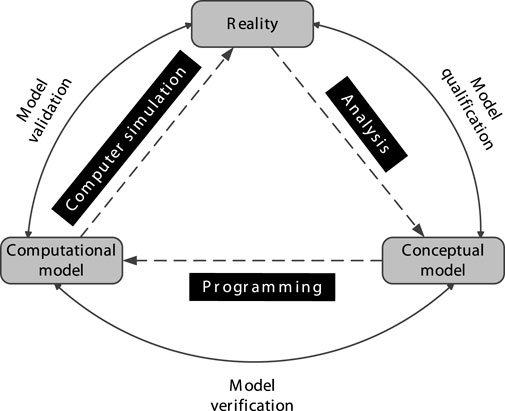
Figure 1. A diagram of a V&V process in modeling and simulation proposed by the Society of Computer Simulation; adopted from (Schlesinger, 1979).
1.1.2.1 U.S. Department of Defense
In the early 1990s, the Defense Modelling and Simulation Office of the U.S. Department of Defense developed expertise and published fundamental concepts and definitions for V&V of a model (DoD, 1994). According to their definitions:
• Verification is the process of determining whether a model implementation accurately represents the developer’s conceptual description of the model.
• Validation is the process of determining the degree to which a model is an accurate representation of the real world, based on the intended uses of the model.
The key feature of these definitions is the emphasis on accuracy, assuming that the measure of accuracy can be determined relative to an accepted criterion. For verification, the reference criteria could be an accepted solution of simplified model problems or an expert opinion. In validation, the referenced criteria could be experimental measurement data or expert opinions.
1.1.2.2 American Institute of Aeronautics and Astronautics
The American Institute of Aeronautics and Astronautics (AIAA) played a pioneering role in defining key terms and standardizing the methodology for V&V in the engineering community. In 1998, academia, industry, and government representatives collaborated to prepare “A Guide for the Verification and Validation of Computational Fluid Dynamic Simulation” which was later reaffirmed in 2002. This guide standardized the basic terminology, concepts, and methodology for V&V in Computational Fluid Dynamics simulations (AIAA, 1998). The AIAA definitions for the terms model, modeling, and simulation are as follows:
• Model: A representation of a physical system or process intended to enhance our ability to understand, predict, or control its behavior.
• Modeling: The process of constructing or modifying a model.
• Simulation: The exercise or use of a model. In other words, a model is used in a simulation.
• The definitions of verification and validation, with some minor modifications, were based on the DoD terms (Figure 2):
• Verification: The process of determining that a model implementation accurately represents the developer’s conceptual description of the model and the solution to the model.
• Validation: The process of determining the degree to which a model is an accurate representation of the real world from the perspective of the intended uses of the model.
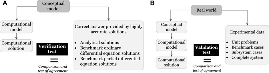
Figure 2. Diagrams illustrating AIAA verification and validation process; adopted from (AIAA, 1998). (A) Verification. (B) Validation.
The AIAA method is a subset of the overall integrated system safety analysis of the Society of Automotive Engineers International (SAE). The SAE’s Aerospace Recommended Practice (ARP) guidelines, particularly ARP 4754A (SAE, 2010), widely applied in the process of airworthiness certification in the highly-integrated or complex electronic system of civil aircraft since 1996 are mandatory requirements for public airplane safety. Interaction between safety and development process is shown in Figure 3. Coverage of the software aspects is dealt with in a jointly developed by the Radio Technical Commission for Aeronautics and European Organisation for Civil Aviation Equipment documents, which are the primary references by which the certification authorities approve all commercial software-based aerospace systems.
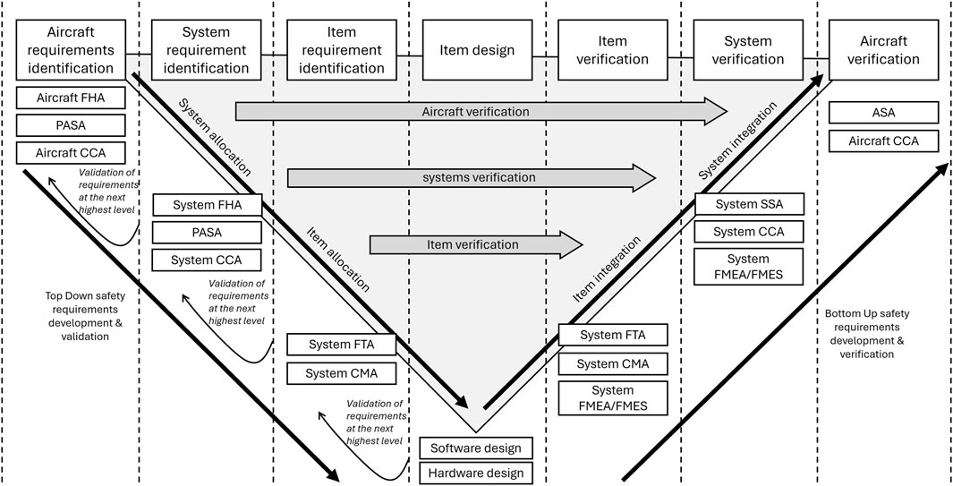
Figure 3. Interaction between safety and development process; adopted from ARP 4754A (SAE, 2010). FHA: Functional Hazard Assessment; PASA: Preliminary Aircraft Safety Assessment; ASA: Airplane Safety Assessment; FTA: Fault Tree Analysis; CCA: Common Cause Analysis; FMEA: Failure Mode and Effects Analysis; FMES: Failure Modes and Effects Summary; and CMA: Common Mode Analysis.
1.1.2.3 American Society of Mechanical Engineers
In the field of solid mechanics, the American Society of Mechanical Engineers (ASME) published a “Guide for Verification and Validation in Computational Solid Mechanics” (ASME, 2006, Refirmed 2016) and “Standard for Verification and Validation in Computational Solid Mechanics” (ASME, 2019), which adopts with some updates the Department of Defense and AIAA definitions. The ASME concept of verification and validation in computational solid mechanics is illustrated in Figure 4 that provides an integrated framework.
• Validation: The process of determining the degree to which a model is an accurate representation of the real world from the perspective of the intended uses of the model.
• Verification: The process of determining that a computational model accurately represents the underlying mathematical model and its solution.
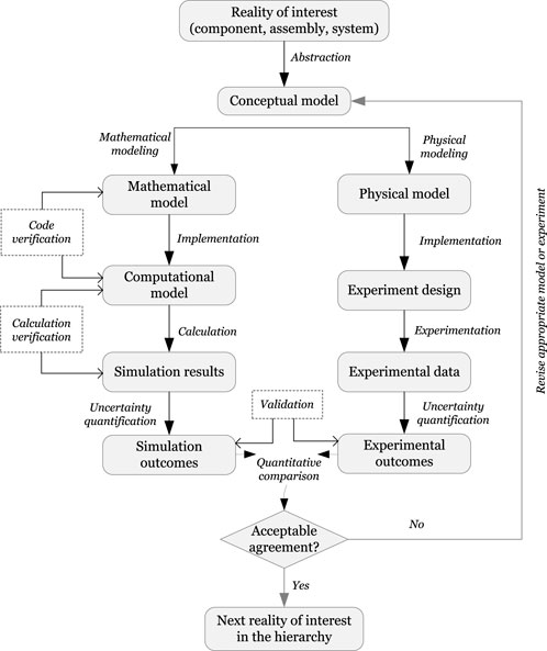
Figure 4. An ASME verification and validation process; adopted from (ASME, 2006, Refirmed 2016).
1.1.2.4 International Commission on Large Dams
The importance of verification, validation, and quality assurance of the analysis results for concrete dams has been emphasized and discussed in various publications of the International Commission on Large Dams (ICOLD). In ICOLD Bulletin No.94 (ICOLD, 1994) the terms justification, validation, and quality assurance were introduced as the critical aspects of computer software use. Since rigorous definitions of these three terms were considered to be too difficult to formulate (probably too abstract to be of real use), the bulletin explains the terms in a more descriptive form.
• Justification concerns the whole analysis process relevant to physical reality and demonstration that the ideal physical model (the theory, mathematical formulation of the theory, the numerical code solving the relevant equations, and the analyst choices), gives a “reasonably close” approximation of the behavior of the real structures.
• Validation is described as the activities tending to satisfy the user that the software to be used gives the “correct answer” to the computational problems intended to be solved. This means that all the numerical codes resorting to the same theory and assumptions will give fairly consistent results when applied to the same problem.
• Quality assurance is associated both with the validation and justification aspects of solving engineering problems and can be ensured by proper documentation and procedures covering justification and validation for a particular application, so it can be exactly repeatable in the future. This means that quality assurance can not guarantee correct results but, at least, it constrains the user on every choice and avoids shortcuts of implicit assumptions that may jeopardize the reproduction of outcomes.
The definition of validation in ICOLD Bulletin No.94, different than one formulated by the cited above organizations, was further described in ICOLD Bulletin No. 122 (ICOLD, 2001) and Bulletin No.155 (ICOLD, 2013) as a vital element of the decision process so that the numerical models and the respectively associated software can be trusted and users have confidence in the computed results. In common practice, validation of the numerical analysis results would be conducted versus classical theory, experimental data, published data, and performance of similar structures. In this context, the benchmark studies would prove their usefulness toward the two types of software qualifications: validation and justification.
1.1.2.5 Recapitulation
The terms verification and validation are often used interchangeably in the common engineering language; however, they have distinct meanings and different roles in a V&V process, as explained in subsequent sections of the paper. To preface, the difference between verification and validation is explained neatly by Roache (1988), where verification means solving the equations right but validation means solving the right equations.
Although several other definitions of verification and validation have been provided by various technical reports and academic publications, the listed above definitions are the primary ones used by the authors of this paper to formulate the V&V process for analyses of concrete dams.
1.1.3 Uncertainty sources and classification
Uncertainty refers to the lack of knowledge or certainty about a future outcome. It may arise due to a lack of information, data variability, the complexity of a system, or the inability to accurately predict an outcome.
In the domain of probabilistic analysis of structural models, Uncertainty Quantification (UQ) refers to “the systematic study and reduction of uncertainties, both in computational simulations and real-world scenarios.” Its primary objective is to assess the likelihood of specific outcomes, considering incomplete knowledge about certain aspects of the system. This section provides an in-depth exploration of the core principles in UQ for structural systems, encompassing various terminologies related to risk-based assessment and failure probability.
Two primary types of UQ problems exist: Forward propagation of uncertainty involves propagating uncertainty sources through the model to predict the overall uncertainty in the system output, e.g., Monte Carlo Simulation and Taylor series. The second type is the inverse assessment of model uncertainty and parameter uncertainty, which requires simultaneous calibration of model parameters using test data, e.g., Bayesian updating.
In civil engineering, the uncertainty classification proposed by Ayyub and Chao (1997) (Figure 5) is extensively used. This classification categorizes uncertainties into abstracted uncertainties, arising from elements of the real system presented or simulated in a model, and cognitive uncertainties, resulting from subjective abstractions of reality. Analysts or engineers may conveniently divide uncertainties into abstracted and non-abstracted aspects based on their knowledge, background, and general state of knowledge about the system. Non-abstracted sources of uncertainty include physical randomness, vagueness, human and organizational error, and conflicts and confusion in information. The framework presented by Ayyub and Chao (1997) is a classic and comprehensive classification used in civil engineering applications. Notable works in uncertainty quantification in structural engineering include those by Melchers and Beck (2018) and Bulleit (2008), which will be discussed in detail later.
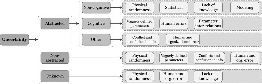
Figure 5. Uncertainty classification in civil engineering; adapted from Ayyub and Chao (1997).
Uncertainty quantification plays a crucial role in every probabilistic risk assessment framework (Winkler, 1996). This importance is amplified when dealing with critical structures (Ellingwood, 1998) and intricate systems, such as concrete dams. Early works on nuclear power plants have taken uncertainty in the numerical simulation of structural systems seriously (Kennedy et al., 1980). According to Parry (1996), uncertainty is classified into three types:
1. Parameter uncertainty: This type addresses uncertainty in quantifying a model with a specified functional form.
2. Modeling uncertainty: This category deals with the uncertainty surrounding the appropriateness of the structure or mathematical form of the model.
3. Completeness uncertainty: This special category of model uncertainty is associated with the extent to which the model encompasses all the phenomena related to the system being simulated.
All variables in the built environment can be classified into two categories: epistemic uncertainties and aleatory uncertainties. This widely adopted classification has been utilized by several researchers, including (Helton, 1994; Paté-Cornell, 1996; Kelly and Campbell, 2000; Helton et al., 2010), and is explained below.
1. Aleatory uncertainty, also known as objective uncertainty (Ang, 1970), represents the inherent randomness of a phenomenon. For example, in the context of seismic analysis of concrete dams, the uncertainty associated with earthquake events (e.g., intensity, time, and return period) is considered the most significant uncertain parameter (Der-Kiureghian and Ditlevsen, 2009). Typically, aleatory uncertainty is quantified using random variables (RVs) within the mathematical framework of probability theory (Ang and Tang, 2007).
2. Epistemic uncertainty, also referred to as subjective uncertainty, arises from a lack of knowledge. An example of epistemic uncertainty is the uncertainty in material properties, such as concrete dam or rock foundation mechanical properties. This category encompasses various sources of uncertainty, including model uncertainty and statistical uncertainty (Ang and Tang, 2007; Melchers and Beck, 2018; Chen and Wan, 2019). The epistemic uncertainty of a continuous random variable, where randomness is quantified by the probability density function (PDF), can manifest in different types: (I) Different shapes of PDFs with identical mean and standard deviation (STD), (II) Different PDFs with different mean and STDs. (III) Same shape of PDF with different mean and/or STDs.
1.2 Research significance, contributions, and scope of the work
The need for further research in the structural analysis of concrete dams is driven by the increasing complexity and demands for safety and reliability in dam engineering. Despite advancements in computational power and numerical methods, several challenges remain unresolved, particularly in accurately simulating interactions between dams, reservoir water, and rock foundations under various loading conditions, as well as the failure mechanism, and limit state definition.
This paper provides a critical synthesis, and introduces a structured framework for the systematic application of verification, validation, and uncertainty quantification concepts within the domain of concrete dam analysis, catering specifically to engineers in this field. Initially, it furnishes a comprehensive exposition of fundamental terminology encompassing verification, validation, calibration, and uncertainty. These definitions are rigorously aligned with corresponding concepts in diverse engineering disciplines, such as aeronautics and astronautics, and adhere to established standards set forth by engineering societies like ASME.
Subsequently, Section 2.1 outlines the construction of a dedicated framework for an analysis process specific to the context of concrete dam engineering. This is followed by a high-level survey of the analytical methods employed for the performance assessment of concrete dams in Section 2.2.
In Section 3, an extensive examination is conducted on three primary sources of uncertainty encountered in concrete dam analysis, namely, loading uncertainty, material randomness, and modeling uncertainties. Also, a discussion is provided on the differences between uncertainty and error.
Section 4 dives into the notion of verification, with a particular emphasis on code verification, solution verification, and sources of errors in numerical simulations. This section offers an exhaustive elucidation of the verification process tailored to the domain of concrete dams with the illustration of selected methods used in the verification of the analysis results.
Section 5 elucidates the validation process within the context of concrete dams, encompassing various categories of experiments and an evaluation of error sources inherent to each. It addresses the challenges associated with the validation process and expounds upon the concept of calibration. Furthermore, it provides a comprehensive account of validation through laboratory and field data.
This paper effectively establishes a unified methodology to instill confidence in the analysis of concrete dams by systematically addressing all relevant procedural steps, emphasizing their significance, elucidating challenges, and highlighting the consequences of neglecting them.
2 Structural analysis methods of concrete dams
Assessment of the structural integrity of concrete dams necessitates the adoption of specialized techniques and the application of sophisticated analysis methods that diverge from standard civil engineering practices. This section introduces a flowchart (serving as a road map) that delineates the analytical process, alongside defining essential terms and computational strategies pertinent to concrete dam analyses.
2.1 Concrete dam structural analysis framework
The analysis process for concrete dam-foundation-reservoir systems (a.k.a. a system) encompasses several critical steps that need to be followed sequentially to ensure the analysis’s quality and reliability. Adhering to this process and employing precise terminology is vital for effective communication within the engineering team conducting the analysis. Figure 6 illustrates a general road map for advanced analysis of concrete dams. The interpretation of the flowchart in Figure 6 starts with a Real Object, the actual dam structure, the foundation, and the reservoir, along with all operational and exceptional conditions. This initial stage lays the groundwork for a thorough understanding and analysis by capturing the physical reality of the dam and its environment, which is essential for an accurate modeling process (Salamon and Jeremic, 2021).
• A Conceptual Model is a “virtual image” of the Real Object. The Conceptual Model of a concrete dam is defined by the nominal dimensions, estimated material properties, and the loads acting on the dam in the form of water pressure, body loads, seismic excitation, temperature, and ice cover thrust in cold regions.
• A Mathematical Model, expressed by a system of partial differential equations (PDEs) with the boundary and initial conditions, is a mathematical representation of the Conceptual Model.
• A Computational Model is represented by the analytical or numerical solutions of the Mathematical Model. The number of available analytical solutions related to concrete dam modeling is very limited; as a result, in such simulations, numerical methods are commonly used instead.
• A computer program (Software) is an automation process of the Computational Model.
• The V&V process is of particular importance in the advanced analysis. It starts with the realization of uncertainties introduced into analysis through simplifying assumptions made for the conceptual, mathematical, and computational models.
• Calibration is a process of adjusting physical parameters in the Conceptual Model to improve agreement with experimental data, field measurements, or in agreement with an expert opinion. It is assumed that if most physical parameters of the conceptual model are properly calibrated, simulation results will well represent the realistic behavior of the real object.
• An important aspect of the analysis is the proper interpretation of the results and presentation of those results in terms commonly used by the engineers. Accurate post-processing and proper presentation of the analysis results to the regulatory agencies (decision-makers) is critical for taking appropriate action.
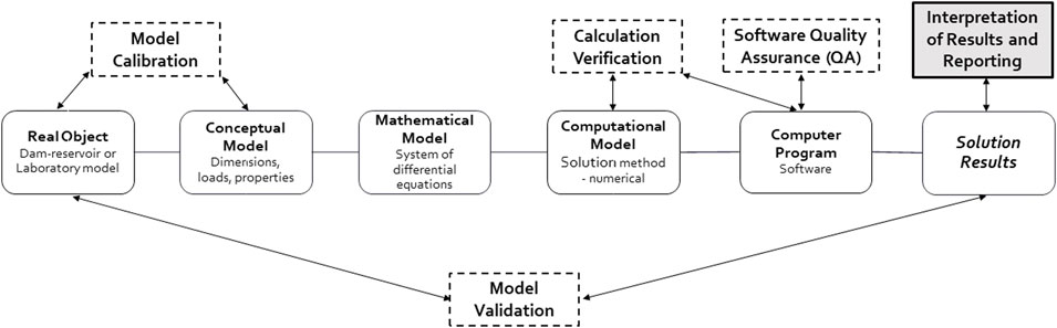
Figure 6. A road map for advanced an analysis of concrete dams; adapted from Salamon and Jeremic (2021).
The entire analysis process can be divided into modeling and simulation, where modeling includes building conceptual and mathematical models, and simulation is related to solutions of mathematical equations.
2.2 Methods used in the analysis of concrete dams
The evaluation of a dam’s structural performance involves employing distinct analysis techniques. The methods can be categorized in general as follows (Figure 7):
• Deterministic methods: These methods aim to find solutions for a single dam-reservoir-foundation model (a system), accommodating various levels of complexity.
• Probabilistic methods: By iterating around deterministic approaches, these methods quantify uncertainties linked to modeling parameters, material properties, and loads (see Section 3).
• Heuristic (proxy) methods: These approaches combine deterministic and/or probabilistic methods with advanced statistical, optimization, or machine-learning techniques to enhance efficiency and speed in problem-solving.
• Experimental methods: This category encompasses techniques involving practical experimentation to gain insights into dam behavior.
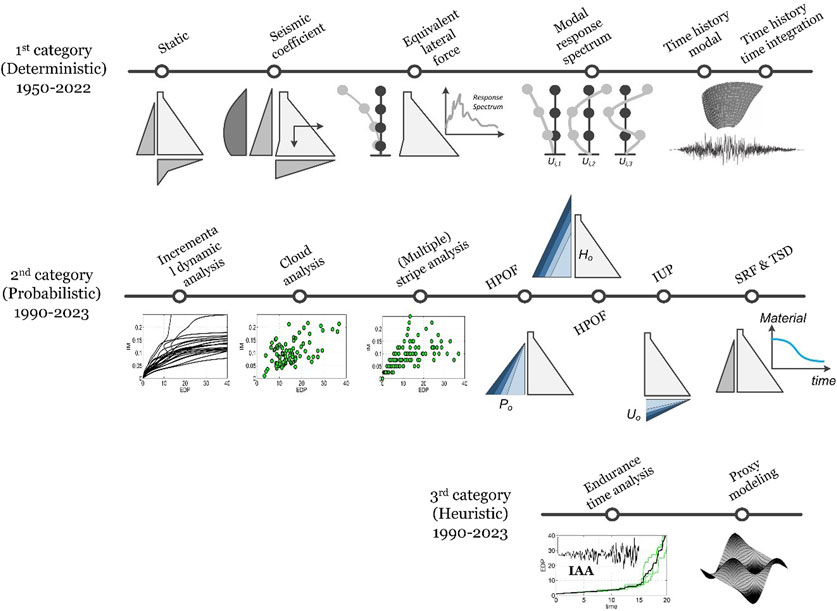
Figure 7. Classification and progress of performance evaluation methods in concrete dams.
2.2.1 Deterministic methods
Several methods have been used in the engineering practice for structural analysis of concrete dams. Some of the methods are briefly presented in this section. Methods for static analyses include:
• Simplified Methods: Simplified methods such as gravity analysis method are widely used for static analysis of concrete gravity and buttress dams. The approach relies on rigid body equilibrium and beam theory to determine forces and stresses in the structure. Assumptions include linear stress distribution and limited interaction between different parts of the dam. This method is useful for the stress and stability analysis of a single dam monolith. For concrete arch dams, the traditional Trial-Load Twist Analysis method is commonly used in engineering practice where the 3D geometry effects of the dam can be modeled based on the equilibrium of the arch, and cantilever displacements and stresses are determined based on the classical beam theory.
• Advanced Methods: Modern concrete dam analyses use numerical methods, primarily the FEA method, for more advanced structural analyses of arch or gravity dams with grouted joints. In such an approach, 3D effects and linear or nonlinear dam behavior are considered.
Methods for dynamic analyses include:
• Seismic Coefficient Method: Also referred to as pseudo-static analysis, this method traditionally assesses seismic stability in gravity dams (USACE, 1995; USACE, 2007). Earthquake forces are treated as static forces combined with various loads such as hydrostatic, uplift, backfill soil, and gravity loads. The dam and foundation are treated as a rigid body and the reservoir is modelled by a hydrostatic pressure. Dynamic loads in the form of inertia forces are determined by multiplying the ground acceleration by the mass of the dam and the equivalent added mass of the reservoir.
• Equivalent Lateral Force (ELF): Known as a pseudo-dynamic analysis is akin to pseudo-static but acknowledges dynamic amplification of inertia forces along the dam’s height, without considering their oscillatory nature. The assumption is that the dam deforms according to its first-mode natural vibration. Higher modes are accounted for through a “static correction method” (Fenves and Chopra, 1985). The responses of the first mode and higher modes are combined using the square root of the sum of the squares (SRSS). This approach is limited to linear elastic models.
• Modal Response Spectrum Analysis: Similar to the ELF method, this approach relies on spectral response analysis. The difference lies in selecting enough modes to encompass at least 90% of the total mass (FERC, 1999). Maximum modal responses are computed for each mode, and total responses are calculated using SRSS for all directions and modes (USACE, 2007). Linear elastic models are a prerequisite for this method.
• Time History Modal Analysis: Building upon the modal response spectrum approach, this method employs acceleration time histories for earthquake demands and provides displacement and stress histories as results. Unlike the previous method, it furnishes time-dependent information, while still being limited to linear elastic behavior (Chopra, 2020).
• Direct Time-History Integration Analysis: This technique involves solving the mathematical model through time-domain integration using various numerical methods (implicit, explicit). It accommodates factors like fluid-structure interaction, soil-structure coupling, and damage response, making it suitable for both linear and non-linear models (Saouma and Hariri-Ardebili, 2021b).
2.2.2 Probabilistic methods
While deterministic methods reveal dam response under specific conditions, they fail to incorporate uncertainties in both conceptual and computational model parameters. To address this gap, the probabilistic approach can be used.
• Probabilistic Seismic Analysis Methods: There are different methods to account for the ground motion variability in the analysis of dams including incremental dynamic analysis, cloud analysis, and stripe analysis. These methods further are discussed in Section 3.
• Hydro-Pressure Overload Factor (HPOF): This method hones in on load uncertainty, simulating bearing capacity determination. It involves overloading the upstream water pressure progressively while maintaining other properties (Li and Ren, 2013). It finds utility in calibrating physical model experiments with hydrostatic pressure.
• Flood Overload Factor (FOF): FOF focuses on potential flood-induced pressures to assess capacity. By gradually elevating the water head, it analyzes dam response to flood pressures (Comi et al., 2009). This method could lead to similar capacity curves as of HPOF for gravity dams, but differences might arise for arch dams.
• Incremental Uplift Pressure (IUP): Similar to HPOF and FOF, IUP explores dam stability as uplift pressure increases incrementally.
• Strength Reserve Factor (SRF): SRF studies ultimate resistance and material strength uncertainties, enabling a grasp of structural strength reserves (Wei et al., 2008).
• Time-Dependent Strength Degradation (TSD): TSD addresses uncertainties in time-dependent phenomena like creep, shrinkage, and alkali-aggregate reaction, observing their effects under specific environmental conditions.
2.2.3 Heuristic (proxy) methods
Another category of performance evaluation methods covers the heuristic/proxy approaches, underpinned by optimization, advanced statistics, and machine learning principles. This domain predominantly encompasses cutting-edge techniques, yet to be integrated into everyday engineering practices. This category can be classified into two main groups:
• Endurance Time Analysis (ETA): ETA employs dynamic pushover procedures, employing a pre-designed function called intensifying artificial acceleration (IAA) to excite the dam (Hariri-Ardebili and Saouma, 2015; Hariri-Ardebili et al., 2016a; Salamon et al., 2019; Hariri-Ardebili et al., 2024). ETA’s objective is to subject structures to a broad range of seismic intensities in a single simulation, from linear to nonlinear response stages. ETA distinguishes itself from probabilistic methods like IDA by requiring only a handful of dynamic simulations.
• Machine Learning-Aided Methods: The combination of machine learning capabilities (and artificial intelligence techniques) with deterministic or probabilistic methods expedites performance evaluation (Hariri-Ardebili et al., 2023). In deterministic methodologies, machine learning predicts structural responses or spectral values using a limited segment of initial ground motion data or the variation of the pool elevation, temperature, and humidity (Chen et al., 2020; 2021; Lin et al., 2023). In probabilistic simulations, machine learning algorithms streamline the simulation process, predicting a substantial portion of the required simulations (Hariri-Ardebili et al., 2022a; Hariri-Ardebili and Pourkamali-Anaraki, 2022; Salazar and Hariri-Ardebili, 2022; Li et al., 2023; Amini et al., 2024).
2.2.4 Experimental methods
Experimental methods have been used in the past to design several concrete dams but in general, they are primarily employed to validate engineering computations. A few selected experimental methods include:
• Experimental photoelastic stress analysis was pioneered by Coker and Filon at the University of London in the 1930s (Moody and Phillips, 1962). Photoelastic studies were implemented for example, by Reclamation to assist in the planning and design of Grand Coulee Dam in 1934 (Reclamation, 1967) and the method was then successfully implemented to support the design of many other dams and appurtenant structures worldwide.
• Electric Analogy Tray Method draws parallels between structural and electrical elements, relating force to current, displacement to voltage, and stiffness to resistance. The dimensional characteristics of a structure are incorporated using transformers and proper current. In the design of C.C.Cragin Dam (formerly Blue Ridge Dam) in 1964, the dam model was segmented into eight vertical cantilevers and six horizontal arches. The grid size was constrained by the availability of resistors, generators, and transformers. The strategic distribution of this equipment across the arch enabled the measurement of stress conditions at over 40 locations.
• Rubber Membrane Models: These models aid in shaping arch dams optimally for hydrostatic loads. The rubber membrane is tailored to fit the valley’s contour and is subsequently loaded with water. This approach operates on the principle that the rubber, capable of bearing tensile but not compressive stresses, will naturally adopt a shape with the most uniform distribution of tensile stresses. Consequently, when this shape is replicated in concrete and subjected to loading from the opposite side, it will achieve a uniform distribution of compressive stresses.
• Ambient (Daniell and Taylor, 1999; Darbre et al., 2000; Oliveira and Mendes, 2006; Sevim et al., 2012; Calcina et al., 2014) and Forced (Loh and Wu, 2000; Cantieni, 2001; Gomes and Lemos, 2020; Hall and Duron, 2022) Vibration Testing: These experiments uncover dynamic characteristics of concrete dams under varying load intensities. Accelerometers or velocimeters capture vibrations, serving mode shape validation, frequency confirmation, structural health monitoring, and performance-based assessments.
• Laboratory Model Testing: Employing small-scale models, shaking table experiments, centrifuge tests, and photo-elastic stress analysis techniques offer insights. Shaking table experiments (Tinawi et al., 2000; Chowdhury et al., 2001; Morin et al., 2002) recreate dam behavior under dynamic excitations, while centrifuge testing (Plizzari et al., 1995; Uchita et al., 2005; Kim et al., 2011) replicates high-speed rotation effects on concrete dams for both static and dynamic investigations. This technique reproduces prototype stress fields, accounting for gravity’s impact on material behavior, thus mimicking prototype properties.
3 Uncertainty quantification
In the context of structural engineering, especially in the context of dam engineering, a comprehensive understanding of uncertainty sources is vital for accurate and reliable assessments. Uncertainties in structural responses emerge from various sources, each requiring distinct treatment strategies to enhance the overall reliability of the system. This section presents an in-depth classification of uncertainty sources, focusing on the ground motion record-to-record variability, a crucial factor in seismic probabilistic assessments for dams.
3.1 Loading uncertainty
The structural behavior of dams is subject to a multitude of operational and extreme loading conditions that encompass gravity, hydrostatic, hydrology, thermal, seismic loads, and time-dependent internal forces developed by creep and shrinkage in concrete. Uncertainties accosted with each of these loading sources introduce unique challenges to the analysis of dams.
Static loads encompass the weight of the dam itself, as well as any permanent fixtures or elements attached to it. Variations in material densities, geometric irregularities, and the installation process can lead to uncertainties in these loads. Mechanical equipment, such as gates, valves, and turbines, introduce additional variability due to manufacturing tolerances and installation discrepancies. Hydraulic loads, stemming from factors like reservoir water level fluctuations and wave action, carry inherent uncertainties influenced by environmental conditions and hydrological modeling accuracy.
Long-term loads, such as creep and shrinkage in concrete, are especially pertinent in concrete dams. Concrete, a time-dependent material, undergoes deformations over extended periods due to factors like moisture content and temperature variations. These deformations can influence the structural integrity and performance of a dam over its service life, introducing uncertainties that need to be accounted for in the analysis process.
In the following sections, we narrow our focus to the specific challenge of seismic loading uncertainty within the context of concrete dam engineering. One of the pivotal challenges in seismic risk assessment for dams lies in the inherent variability of ground motion records from earthquake events. This ground motion record-to-record (RTR) variability stems from the unpredictable nature of earthquakes, leading to diverse ground shaking patterns across different seismic occurrences. Capturing this variability is of paramount importance to comprehensively understand the potential range of responses that a dam may experience during various seismic events. By embracing the full spectrum of seismic input uncertainties, a more robust foundation for probabilistic assessments is established, ultimately enhancing the effectiveness of structural evaluations and risk management strategies.
The Incremental Dynamic Analysis (IDA) method stands out as a notable approach to address the complexities of RTR variability. This method involves utilizing a relatively large number of ground motion records, typically around 40, and scaling them at various seismic intensity levels (SILs) (Vamvatsikos and Cornell, 2002). Through nonlinear simulations, key response parameters such as peak displacement, stress, or damage indices are recorded for each scaled ground motion record. The collection of these results produces a single-record IDA curve when connecting the points. By aggregating individual IDA curves, a multi-record IDA is obtained, offering comprehensive insights into the structural behavior under varying seismic conditions. The IDA method has found widespread application in assessing diverse dam types, including gravity dams (Alembagheri and Ghaemian, 2013a; Alembagheri and Ghaemian, 2013b; Wang et al., 2015a; Soysal et al., 2016; Chen et al., 2019; Mahmoodi et al., 2021) and arch dams (Alembagheri and Ghaemian, 2013c; Pan et al., 2015; Alembagheri and Ghaemian, 2016; Wang et al., 2018; Jin et al., 2023).
An alternative method known as Multiple Stripe Analysis (MSA) bears similarities to IDA, but with discrete results at different intensity levels. Originally, MSA employed the same set of ground motions for all stripes (Jalayer and Cornell, 2009). However, a modified version incorporates distinct ground motion records across various SILs, aligning with conditional ground motion selection (Mackie and Stojadinovic, 2005). MSA has demonstrated its utility in dam engineering contexts (Hariri-Ardebili et al., 2016b; Segura et al., 2020; 2019). Cloud Analysis (CLA), on the other hand, involves a substantial number of unscaled ground motion records, typically around 100–200, spanning a wide range of SILs. Applications of CLA in dam engineering are well-documented (Hariri-Ardebili and Saouma, 2016a; Yazdani and Alembagheri, 2017; Alembagheri, 2018; Hariri-Ardebili et al., 2022a; Tidke and Adhikary, 2022; Gorai and Maity, 2023). Figure 8A illustrates a sample RTR variability for a dam model with 300 unscaled ground motion records in a logarithmic scale where the seismic intensity is presented by peak ground acceleration (PGA) and the engineering demand parameter is the crest maximum relative displacement.
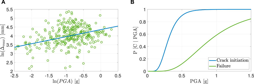
Figure 8. Addressing the ground motion RTR variability with cloud analysis and the associated fragility functions. (A) Ground motion RTR variability. (B) Fragility functions with two limit states.
Given the extensive simulations inherent in probabilistic seismic methods, conveying their outcomes effectively is achieved through the presentation of seismic fragility functions (Hariri-Ardebili and Saouma, 2016b). These functions serve as suitable representations of the comprehensive results derived from the rigorous probabilistic seismic assessments. Sample fragility functions are shown in Figure 8B for two limit states: crack initiation, and dam failure.
3.2 Material randomness
In the context of seismic analysis for structural components and systems, the incorporation of uncertainties related to material properties assumes a pivotal role. The presence of variability in various materials of concrete dams and rock foundation attributes necessitates the utilization of statistical distributions, encapsulating parameters such as mean, median, standard deviation, and lower and upper bounds. It is worth noting that assigning a single distinct distribution to a particular material property is not always feasible. This complexity is exemplified by concrete compressive strength, which has been subject to a range of suggested distributions, including normal or lognormal, with coefficients of variation spanning from 0.06 to 0.21 (Kappos et al., 1999; Lee and Mosalam, 2005; Strauss et al., 2009; Barbato et al., 2010; Celik and Ellingwood, 2010; Jalayer et al., 2010; Unnikrishnan et al., 2013; Xu et al., 2018; Ma et al., 2019; Ebrahimi et al., 2020; Li et al., 2020), highlighting the diversity within the literature.
Moreover, when multiple Random Variables (RVs) are integrated into simulations, the consideration of potential correlations among them becomes imperative. Broadly, two types of correlations are typically addressed in the context of dam engineering problems:
Multivariate Correlation: This pertains to the partial or complete correlation between any two RVs associated with a specific material (e.g., concrete modulus of elasticity and compressive strength, represented as
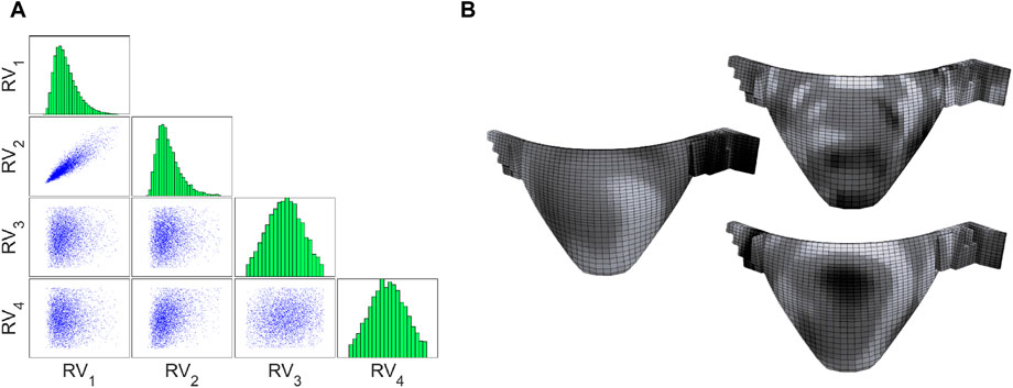
Figure 9. Correlation among random variables in a material uncertainty quantification problem. (A) Multi-variate samples with correlation. (B) Spatial distribution of concrete compressive strength (Hariri-Ardebili et al., 2019).
Spatial Correlation: Another form of correlation, spatial correlation, gains significance when evaluating structural damage and failure, particularly in scenarios involving crack initiation and localization within a uniformly stressed region (Olsson and Sandberg, 2002). This correlation refers to the interconnection between different locations within the structure. Figure 9B portrays three realizations of concrete compressive strength within an arch dam (with three different correlation lengths), highlighting the concept of spatial correlation. Research has extensively explored spatial correlation within material and geometric properties of engineering structures (Grigoriu and Turkstra, 1979; Thoft-Christensen and Sørensen, 1982; Elnashai and Chryssanthopoulos, 1991; Graham and Deodatis, 2001; Buonopane, 2008; Sattar and Liel, 2017; Díaz et al., 2018; Scozzese et al., 2018; Charmpis, 2019). Often, correlation coefficients were treated as random variables in these investigations. For example, Elnashai and Chryssanthopoulos (1991) assumed values of 0.0, 0.7, and 1.0 for
3.3 Modeling uncertainties
Within the context of seismic analysis, uncertainty in response modeling stems from the inherent limitations of an idealized numerical representation in predicting the real-world behavior of engineered systems subjected to ground motions. As articulated by Sattar et al. (2013), modeling uncertainty encompasses the variability linked to the effectiveness of a model in accurately depicting the true structural response (Hariri-Ardebili, 2024). Bradley (Bradley, 2011; 2013) further elucidates this classification, outlining the following sub-categories, as depicted in Figure 10:
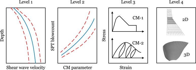
Figure 10. Modeling uncertainty classification; adopted with changes from (Bradley, 2011).
Level 1 Uncertainty: This category pertains to uncertainties inherent in measuring physical quantities, such as concrete tensile strength or rock shear stiffness estimation. Level 1 uncertainty hinges solely on the precision of physical experiments and doesn’t directly impact the numerical model formulation. Nevertheless, these measurements serve as input parameters in numerical simulations, thus influencing the ultimate response predictions.
Level 2 Uncertainty: At this level, uncertainty arises due to the correlation between measurable physical quantities and constitutive model parameters. This form of uncertainty has been observed by researchers like (Haselton and Deierlein, 2006; Lee and Mosalam, 2006). For instance, while concrete compressive strength is typically measured from core samples, certain constitutive models might require direct knowledge of tensile strength. Notably, the Level 2 modeling uncertainty closely aligns with the concept of material randomness discussed in Section 3.2.
Level 3 Uncertainty: Embracing the uncertainty tied to selecting a constitutive model, this level involves assumptions and simplifications specific to a particular project (Aslani and Miranda, 2005). Constitutive models can be empirically derived or theoretically formulated based on certain assumptions. In the context of concrete dams, a gamut of choices exists, including smeared crack models (Willam et al., 1987; Cervera and Chiumenti, 2006; Hariri-Ardebili and Seyed-Kolbadi, 2015), plasticity models (Jirásek and Bazant, 2001; Chen and Han, 2007), damage mechanics models (Bittnar and Šejnoha, 1996; Cedolin and Bazant, 2010), and fracture mechanics models (Bažant and Planas, 2019), addressing concrete behavior during seismic loading.
Level 4 Uncertainty: Encompassing uncertainty in the overarching modeling methodology, this category includes decisions such as employing 3D models for dams with narrow valleys versus utilizing 2D plane strain models (Bybordiani and Arıcı, 2017). It also involves considerations like accounting for dam-foundation or dam-reservoir interactions, where fidelity variations may emerge. Choices regarding boundary conditions, damping formulations, and ground motion input, including assumptions about wave propagation, contribute to this category. For instance, assumptions about dam-reservoir interactions might involve employing simplified Westergaard hydrodynamic pressure or directly determined hydrodynamic loads obtained from solving a coupled fluid-structure interaction problem, further contributing to this layer of uncertainty.
3.4 Segregation of uncertainty and error
In many technical publications and everyday engineering practice, the terms uncertainties and errors are sometimes interchangeably used which may produce a great deal of confusion and misinterpretation of results. Although both terms are complementary, uncertainty and error convey different meanings: uncertainty conveys a sense of doubt, whereas error suggests a mistake (Possolo, 2015). A difference between uncertainty and error in scientific computations is explained neatly by Oberkampf and Roy (2010) where aleatory uncertainty is related to inherent randomness and epistemic uncertainty related to lack of knowledge, but the error is a deviation from the “true” value.
This distinction is similarly upheld in the concepts of measurement uncertainty and measurement error. Measurement uncertainty is a specific type of uncertainty, aligning with the general understanding of the term. However, measurement error does not necessarily arise from a mistake; it is defined as the deviation between a measured value and the “true” value. When the true value is known (or can be estimated with negligible accuracy), the measurement error becomes quantifiable and can be corrected.
For example, if measurements of 25, 16, 26, 23.5, and 26.8 MPa are reported as measured compressive strength of concrete from the same batch, the second test (16 MPa) likely represents a recording error or mistake in testing. The variation among the remaining values illustrates the randomness in material properties and measurement uncertainty.
In another study by Oberkampf et al. (2002), the error is depicted as a recognizable inaccuracy within any phase or activity of modeling and simulation that is not due to a lack of knowledge. This definition posits that inaccuracies are identifiable or discernible upon examination, meaning they are not rooted in ignorance. Essentially, a standard or more precise methodology is acknowledged to be accurate. Should a deviation from this acknowledged methodology be identified, it may be either rectified or left unaddressed. Such deviations might not be corrected due to practical limitations, like cost or scheduling concerns. For instance, an error might be deemed tolerable given the analysis requirements or the prohibitive computational expense of correction. This concept delineates error into two categories: acknowledged or unacknowledged. Acknowledged errors are those recognized by analysts, who generally understand their scope or impact. These include computational limitations like finite precision arithmetic, simplifications made through assumptions or approximations, and the translation of PDEs into discrete numerical models. Conversely, unacknowledged errors are not identified by the analyst but remain identifiable. Examples include blunders or mistakes; for instance, an analyst may inadvertently execute a procedure incorrectly due to human error. Unfortunately, straightforward strategies to estimate, limit, or prioritize the influence of unacknowledged errors are lacking. Occasionally, an unacknowledged error is caught by its originator, such as when a coding mistake is uncovered through a program review, or identified by others via analysis redundancy checks.
Error is a known approximation between computation results and exact/true solutions, while uncertainties arise in simulation due to randomness or lack of knowledge. In the verification and validation framework, distinguishing between these concepts depends on the presence of a “true solution.” Verification involves comparing the computational model with an exact/analytical solution (or the solution determined with certain accuracy)–deemed the “true solution.” Here, any difference is categorized as an error. Validation contrasts by comparing the computer model’s outcomes with real-world physical measurements. Since these measurements can never be perfect or entirely accurate representations of the “true data,” any deviation is labeled as uncertainty, characterized by bias and variance. Additionally, in scenarios where the measurements are unavailable (e.g., due to equipment failure or lack of available measurement data), the computational model’s range of possible outcomes becomes the basis for uncertainty, not error. For instance, in structural analysis of a concrete dam, where tensile strength data might be missing, employing assumed average values and standard deviations introduces uncertainty in the simulation outcomes, rather than errors, since the exact response remains unknown. For example, Figure 11 depicts the variability in estimated frequency response for an arch dam-foundation system using three distinct mesh configurations and idealizations. Mesh 1 offers a detailed representation of both the rock’s topography and the dam’s intricacies, whereas meshes 2 and 3 adopt a simplified model for the canyon and dam. Notably, Mesh 2 contains approximately 10% of the elements found in Mesh 3.
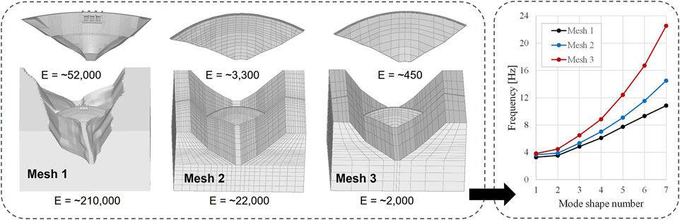
Figure 11. Variability in estimated frequency for different modes in an arch dam-foundation model due to variability in idealization and discretization. Note: E presents the number of elements in either the dam itself or the dam-foundation system together. Source: Hariri-Ardebili and Li (ongoing work).
In a broad classification, the error in a computational model prediction consists of two parts (Oden et al., 2005): model form error
• Error in input data, including geometry, topology, material law, constraints, boundary conditions, and applied loads.
• Idealization error which includes the theoretical aspects and element formulations such as (a) displacement-based Finite Element Method (FEM), mixed methods, theory of elasticity, etc., (b) 1D, 2D, 3D, linear, nonlinear, static, dynamic, (c) plane stress, plane strain, axisymmetric, incompatible modes, (d) 3D solid, and (e) thin, thick plates, shells.
• Discretization error (Mass, Stiffness, Damping, Loading) error which includes (a) mesh and mapping; (b) polynomial degree, (c) integration order, and (d) incompatible modes.
• Numerical errors and ill-conditioning which includes (a) formulation and solution of equilibrium equations, (b) Direct stiffness assembly (banded, skyline, storage), and (c) Gauss elimination, frontal methods, iterative methods.
• Error in stress recovery algorithms which includes proper extraction of displacement, stress, strains, and reactions.
• Error in post-processing and interpretation of analysis results.
4 Verification process
The verification process aims to ensure that the computational model accurately represents the mathematical model and its solution. Although the purpose of verification is to confirm that the computational model is working as intended, the responsibility for selecting and appropriately utilizing the software, solution method, and simulation input parameters, as well as for producing/delivering accurate analysis results, rests entirely with the engineer or analyst performing the analysis. Broadly, the verification process comprises two key components: code verification and solution verification. This process is crucial for the quality assurance of numerical analysis procedures.
As numerical simulations and their outcomes are increasingly used in the design and evaluation of infrastructures, particularly dams, the significance of these verification activities has grown. The last few decades have seen a marked increase in the focus on code and simulation verification. It’s important to acknowledge the following contributions by Roache (1998), Babuška and Oden (2004), Oden et al. (2005), Oberkampf and Trucano (2008), Oberkampf and Roy (2010), Oberkampf and Roy (2010), Roy and Oberkampf (2011), Szabó and Actis (2012), Jeremić et al. (2023).
The ASME developed a set of standards for performing verification and validation in the area of solid and fluid mechanics (ASME, 2006; Refirmed 2016; ASME, 2009; ASME, 2019). The National Aeronautic and Space Administration developed standards for models and simulations (NASA, 2024), while the International Organization for Standardization, International Electrotechnical Commission, and Institute of Electrical and Electronics Engineers jointly developed a standard for the development of simulation programs (ISO, 2018).
The primary objective of simulation verification is to establish the credibility of simulation outcomes and to evaluate the reliability of both computer software and the solution methods employed in the simulation. Verification of the solution serves as proof that the model has been solved accurately, according to Oberkampf and Trucano (2002).
4.1 Code verification
Software (code) verification entails ensuring that the code and implemented numerical algorithms used to solve discrete systems of equations produce accurate solutions. Additionally, it seeks to identify and correct any programming/coding errors. This verification is divided into two main areas: numerical algorithm verification and software quality assurance (QA).
Numerical algorithm verification addresses the mathematical aspects of algorithm implementation within the software. Its primary objective is to evaluate the algorithm’s correct and intended functioning. This evaluation focuses on numerical aspects and is typically conducted through benchmark problem simulations.
The software developer’s QA and quality control (QC) programs primarily handle code verification. These programs encompass static testing, which doesn’t necessitate running the program, and dynamic testing, where the code is executed. Included in dynamic testing is the use of a test harness that subjects the code to a variety of data and conditions, assessing the performance of data handling, drivers, and other tools in different scenarios.
Dynamic testing of FEM software, integral to dam engineering, is classified into four main types: consistency tests, patch tests, benchmark tests, and system tests. Consistency tests engage simple case studies where target outcomes are analytically predictable. Patch tests examine the impact of finite element shapes on analytical results, though neither consistency nor patch tests mimic real-world engineering structures. Benchmark tests involve genuine engineering calculations for scenarios where analytical target values may not be directly available, aiding in the comparison of different FEM software capabilities. System tests focus on the specific functionalities of the FEM software package, such as error messaging, mesh generation, post-processing, and file management. These dynamic tests may be conducted by the software development team internally or in partnership with external customers or stakeholders.
Benchmark tests play a crucial role in the verification processes for FEM software packages. For general applications, these benchmark tests are accessible in commonly available literature. The National Agency for Finite Element Methods & Standards (NAFEMS) has developed and published a significant number of benchmarks (NAFEMS, 1984; 1990; 1992). Regular publications of the benchmark tests, including target values, appear in the NAFEMS Benchmark Magazine (NAFEMS, 2024), the ASME Journal of Verification, Validation, and Uncertainty Quantification, and various engineering and academic publications. For concrete dams specifically, benchmark case studies are available in ICOLD publications (Salamon et al., 2021; ICOLD Bulletin, 2024 in-progress; Hariri-Ardebili, 2024) and numerous conference and journal articles.
While QA/QC processes and numerical algorithm verification constitute standard practices in the context of commercial software development, the evolving landscape of user feedback and regular software updates indicates that these methodologies alone may not be entirely sufficient to instill full confidence in software outcomes. It underscores the indispensable role of user engagement in the software verification process. This engagement not only augments traditional verification methods but also, with the advent of modern technologies, contributes to enhancing the sophistication and dependability of code verification efforts.
Software users need to be familiar with the verification processes that developers use and actively participate in creating additional tests for specific applications. This is because they bear the responsibility of ensuring that the software, in conjunction with hardware and the operating system, delivers reliable and consistent results. User Acceptance Testing is a critical step in this process, where users themselves conduct tests to validate and approve the software for use in their engineering applications.
4.2 Solution verification
Solution (calculation) verification involves ascertaining the accuracy in the selection of the solution method, its parameters, identifying any errors stemming from analyst mistakes during input preparation and post-processing, and evaluating the solution’s accuracy within the simulation (addressing discretization and iterative errors). Errors in computer simulations primarily fall into the following categories:
• Human Errors: Detecting and evaluating human errors during input data preparation and post-processing can be challenging, particularly for complex computational models. This challenge can be mitigated by implementing a robust checking and review process. Section 4.3 furnishes a few practical techniques that can aid in verifying input data for computational models applied to the analysis of concrete dams.
• Numerical Errors: Two distinct types of numerical errors can be identified in computational calculations: round-off errors and iterative errors.
• Round-off errors arise due to the utilization of finite arithmetic on digital computers and can become significant in time-intensive simulations, such as seismic or/and nonlinear analyses of concrete dams. The repeated arithmetic operations degrade the solution accuracy. Employing higher-precision floating-point numbers Kahan (1996) can help mitigate round-off errors. The extent of mitigation depends primarily on the programming language, compiler, software development, and hardware.
• Iterative errors emerge when an iterative method is employed to solve nonlinear problems (utilizing implicit algorithms) or when an iterative approach is adopted for solving systems of algebraic equations. During the iterative process, the difference between the approximate solution at iteration “k” and the exact solution characterizes the iterative error and can be represented as
• Discretization Errors: Discretization errors manifest as differences between the exact solution and a numerical approximation, arising from the discrete representation of partial differential systems based on spatial and temporal discretization. These errors stem from the translation of a continuous variable function into a discrete system within simulations. Two approaches are commonly recognized for estimating errors in a solution: “a priori” and “a posteriori.” In the a priori approach, only information about the numerical algorithm that approximates partial differential operators, along with specified initial and boundary conditions, is utilized. The “a posteriori” error estimation approach combines a priori information with results obtained from multiple numerical solutions to the same problem, employing different discretizations (variations in mesh densities and/or time steps). Comprehensive insights into the general discretization process of mathematical models and estimations of discretization errors can be found in publications like (Bathe and Cimento, 1980; Zienkiewicz and Taylor, 2000). For a more practical understanding of the discretization process and its application to concrete dams, refer to Section 4.3, which provides an illustrative depiction and practical guidelines.
4.3 Demonstrating verification processes for concrete dams
In the following section, some key aspects for software installation and verification of the input and output data are illustrated and some practical guidelines for simulation verification in application to concrete dams are provided.
4.3.1 Verification of software installation
Before initiating any analysis, users must confirm that the installed software accurately replicates results for standard verification problems, typically supplied by software developers. A selection of tests recommended for software users includes:
• Compatibility Testing: This involves assessing the software’s performance across different operating systems, hardware configurations, and network environments. Users should run benchmark examples under varied configurations to compare analysis results, ensuring the software behaves consistently across different setups.
• Installation Testing: Conducted to ensure all components of the software are correctly installed and function as intended. This test includes uninstalling the application to verify that all elements are completely removed from the system, preventing any conflicts with new versions.
• Performance Testing: Evaluates the stability and response time of the software under various conditions, such as concurrent usage of multiple programs, extensive data transfer, or prolonged server load. This test is vital for understanding the software’s robustness.
• Usability Testing: Focuses on the user’s experience, assessing if the software is intuitive and user-friendly. It includes evaluating how the software guides the user through a run, as well as the clarity of warnings and error messages.
• Security Testing: Especially critical for projects dealing with sensitive information, this test checks the software and servers against internal and external security threats, ensuring the protection of data.
4.3.2 Verification of inputs
For the verification of model input data, the user is advised to:
• Confirm the computational model aligns with the predefined assumptions, including the verification of geometry, material models, and loading sequences.
• Check user-defined input parameters such as material properties, load magnitudes and directions, element type parameters, and solution input parameters. It is essential to understand the impact of software’s default and optional input parameters as well as ensure unit consistency across all inputs.
• Verify computation results to check for expected symmetrical outcomes, energy conservation, and overall structural behavior, which can reveal inaccuracies in the input data.
• Evaluate sub-models within the overall conceptual model independently to ensure each component’s accuracy.
• Pay attention to the software’s warning and error messages as they can provide insights into potential issues with input data.
• Implement boundary value testing to identify software input limits, establishing upper and lower boundaries within which the software operates correctly, thus detecting any defects in handling input values.
4.3.3 Verification of output
For the verification of model output data, consider the following steps:
• Examine the dam’s original design and contrast the preliminary analysis outcomes with those documented in the original design files. This comparison helps identify any discrepancies early in the verification process.
• Evaluate the sensitivity of the solutions to variations in time and spatial discretization, element types, and the chosen solution method. Sensitivity analysis is crucial for understanding how changes in model parameters affect the outcome.
• Analyze the stress-strain history at specified integration points, alongside displacement or crack patterns, and stress and temperature contours. Such detailed checks ensure that the model behavior aligns with expected physical realities.
• Inspect the free body diagram cut, total mass, and force equilibrium errors, as well as constraints and contact behavior. Verifying these aspects confirms the model’s overall balance and interaction correctness.
• Assess critical zones, peak values of stresses and displacements, and discontinuities in results. Comparing these findings with auxiliary models or known solutions helps establish bounds for the expected results, providing a framework within which the output data can be judged as reasonable or needing further investigation.
• Evaluate the analysis outcomes with an expert opinion. Consulting with experienced professionals ensures that the results are not only mathematically and logically sound but also practically viable. Experts can provide insights based on their knowledge and experience, helping to identify any overlooked errors or validate the model’s accuracy.
4.3.4 Simulation verification
For the verification of simulations pertaining to concrete dams, several practical considerations should be taken into account (Salamon and Jeremic, 2021; Jeremic and Salamon, 2022), including:
• Compare simulation outcomes with analytical solutions for simplified geometries and material behaviors to identify numerical discretization errors.
• Assess simulation results across different solution methodologies, such as contrasting explicit and implicit solutions, to ensure robustness across computational strategies.
• Examine the impact of varying convergence criteria and tolerances at both the constitutive/element level and the global finite element level, aiding in fine-tuning the simulation for accuracy.
• Analyze the energy balance at both the element and global levels to ensure that the simulation conserves energy appropriately.
• Conduct software-to-software comparisons by analyzing the same model using different programs that offer similar analysis capabilities. This approach helps identify any potential software-specific biases or errors.
• Undertake sensitivity studies to understand the effects of modeling assumptions and simplifications on the simulation results, as well as assess the solution’s sensitivity to model imperfections. This helps gauge the robustness of the findings.
• Benchmark results against a suite of tests specifically designed for concrete dam structures, such as those from the United State Society on Dams (USSD) (Salamon, 2018) and ICOLD (Bolzon et al., 2020; ICOLD Bulletin, 2024 in-progress) benchmark workshops. These comparisons provide a standardized measure of performance and accuracy.
• Evaluate discretization errors related to spatial discretization (element size), load increment size, and time discretization (time step size), crucial for minimizing approximation errors in the simulation.
4.4 Examples of verification processes for dam engineering
From several case studies presented in various publications including (ICOLD Bulletin, 2024 in-progress; Salamon et al., 2021; Hariri-Ardebili, 2024), selected verification techniques are illustrated in this section for representative concrete dam-related examples.
4.4.1 Software to analytical solution comparison
The comparison between software-generated results and an analytical solution for Pine Flat Dam is highlighted in a benchmark study from the ICOLD 15th International Benchmark Workshop on Numerical Analysis of Dams (Salamon et al., 2021). This study showcases a software-to-exact solution verification technique by examining the propagation of a seismic wave through a foundation block sub-model (See Figure 12A), representing a simplified semi-infinite medium. With specific block dimensions, material properties, and a uniformly applied S-wave pulse at the base, the workshop’s participants explored simulations under diverse boundary conditions on the block sides (Hariri-Ardebili, 2024). The outcomes, depicted in Figure 12B showing horizontal maximum and minimum velocities at the free surface at designated points (a, c, e, and g), were contributed by 21 participants. These findings compare numerical solutions employing “nonreflecting” (absorbing) and free-field boundary conditions at the block sides, offering a practical demonstration of software-to-analytical solution verification strategies.
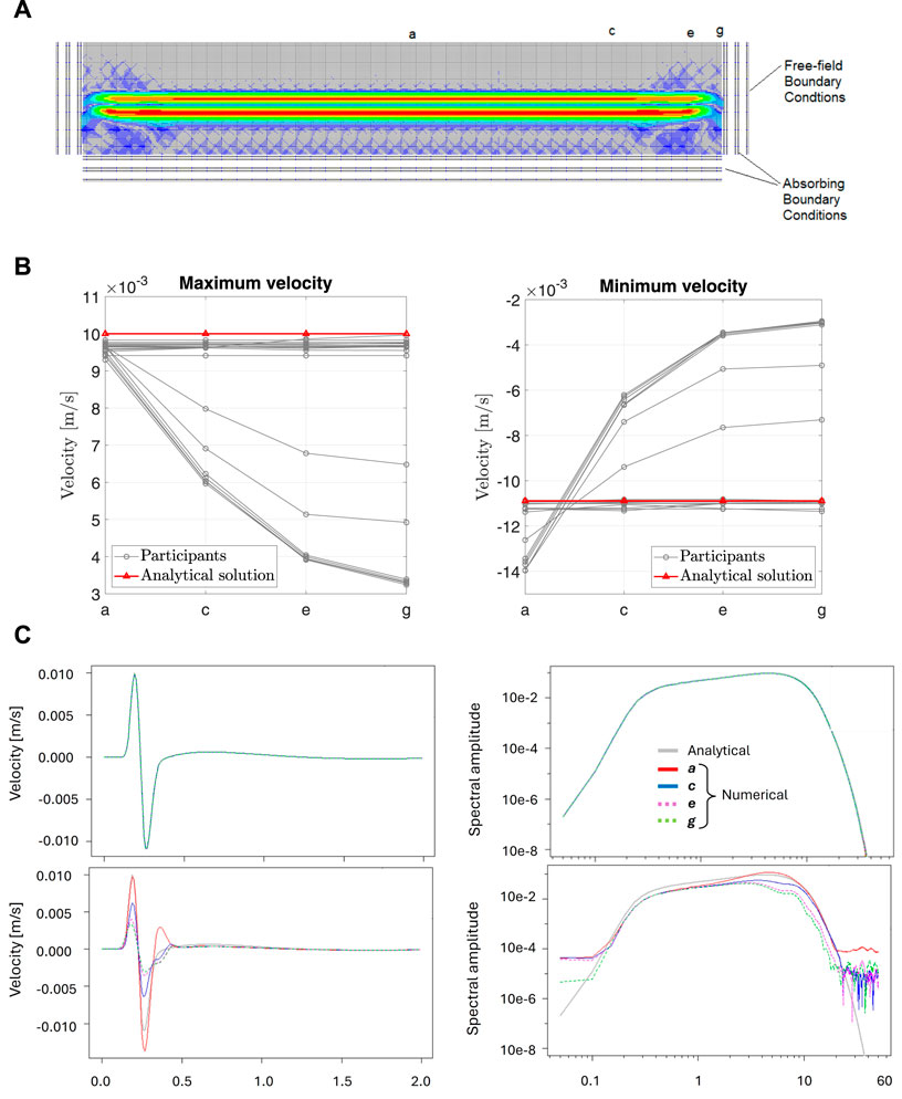
Figure 12. Illustrating the ICOLD benchmark problem for wave propagation in an elastic foundation block including the model, index points, and numerical and analytical solutions. (A) Wave propagation in an elastic foundation block including index points. (B) Comparison of peak velocity at the block surface from ICOLD benchmark workshop participants and the analytical solution. (C) Comparison of free surface velocity records in time and frequency domains from the numerical simulation at four index points and the theoretical solution. Note: far-field BC at the top, and the absorbing BC at the bottom plots. Adopted from (Salamon et al., 2021).
The numerical results are compared with the analytical solution for the problem, theoretically determined from the equivalent up-going motion in an elastic homogeneous half-space. The analytical solution is plotted as a horizontal red line at 0.010 m/s and −0.011 m/s for the maximum and minimum peak velocities, respectively. The uniformly applied wave at the base of the foundation block remains uniform at the top surface of the block for the free-field type boundary, matching the analytical solution. When the “non-reflecting” boundary conditions are used, relatively good agreement with the theoretical solution is observed only at the central part of the foundation block, with significant differences close to the block ends.
The results are also presented in both the time and frequency domains in Figure 12C. Free-surface motions at points a, c, e, and g for the “free-field” model assumption are in good agreement with the theoretical solution (first row), but discrepancies are observed for the “non-reflecting” model assumption at the block sides (second row).
4.4.2 Nonlinear material model comparison
In the ICOLD 15th International Benchmark Workshop, case studies have been formulated to verify engineering software in the field of concrete dam engineering (Bolzon et al., 2020). In this study, the dam and foundation model size, seismic load record, and material properties were defined by the formulators. Participants conducted nonlinear analyses using software, concrete material models, and mesh discretization of their choice. The comparison of damage profiles obtained by participants for a selected case study is presented in Figure 13. An in-depth summary and discussion of the results are provided in (Bolzon et al., 2020; Hariri-Ardebili, 2024), with primary observations as follows:
• The choice of nonlinear model and solution technique significantly affects the nonlinear analysis results, with uncertainty being greater in nonlinear analysis than in linear cases. Participants employed a range of approaches in simulating the dam-foundation-reservoir system, resulting in divergent solution outcomes.
• Key factors highly influencing the results of nonlinear analysis for seismic loads include the type of material model implemented in the software, finite element mesh size, time integration methods, and corresponding step size, as well as convergence criteria. Other factors affecting the results are the application of “free-field” versus “absorbing” boundary conditions to the foundation domain, modeling of Fluid-Structure Interaction (FSI) effects, and the use of implicit or explicit time integration methods.
• Variability emerged in the assumptions governing the representation of concrete damage under dynamic loading conditions. Participants adopted a range of techniques, from complex damage plasticity models to more simplistic tension-based models.
• Distinctions were observed in the choice of finite element type and mesh size, which ranged from 0.5 m to 10 m for the primary dam body. There was also variability in time steps, spanning from 5e-5 s for explicit solutions up to 0.01 s for implicit solutions.
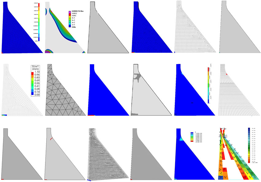
Figure 13. Estimated damage profile for Pine Flat Dam subjected to Taft ground motion record.
In conclusion, seismic analysis of concrete dams with nonlinear material behavior is a complex problem. The outcomes of such simulations are extremely difficult to assess, and the accuracy of these solutions is challenging to estimate.
4.4.3 Verification of time integration methods
In the time-dependent load solutions for seismic analysis of concrete dams, various direct integration methods are used that can be classified as either explicit or implicit. The selection of an integration method, its parameters, and the size of time steps directly influence the accuracy of the model response. A comprehensive summary and comparison of six direct integration methods are provided in a technical report by Ebeling et al. (1997) for a single-degree-of-freedom system, as part of the USACE “Time Domain Solutions for Nonlinear Problems of Concrete Dams,” and by Chopra (2010).
For the foundation sub-model shown in Figure 12A, the influence of time integration step size on the propagation of a Ricker wavelet with a predominant frequency of 25 Hz is illustrated in Figure 14 (Salamon and Jeremic, 2021). The impact of time step sizes of 0.001, 0.005, and 0.01 s on the recorded accelerations at the center of the block’s free surface (point a, Figure 12A) for a uniform mesh size of 2 m is shown. For the 0.001-s time step, the computed accelerations are in very good agreement with the theoretical solution, but they vary for larger time steps of 0.005 and 0.01 s.
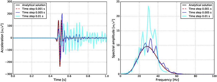
Figure 14. Verification of time-step. Acceleration time series and response spectra at point a of Figure 12A. Adopted from (Salamon and Jeremic, 2021).
Explicit analysis can be executed very efficiently and quickly; however, it does not inherently check for equilibrium. The equilibrium path can be followed closely depending on the size of the incremental/time step, but this is not verified, and thus equilibrium for analysis results cannot be guaranteed. Conversely, implicit analysis does verify equilibrium and takes measures to satisfy it within a specified tolerance. To ensure the accuracy of analysis results, it is advisable to perform both explicit and implicit analyses when possible. This approach allows the engineer or analyst to assess the reliability of the results obtained from explicit analysis. Additionally, explicit analysis should be repeated with variations in incremental/time step size to evaluate the influence of step size on the results.
4.4.4 Verification of spatial discretization
Mesh size and discretization significantly impact both static and dynamic analysis results. The effect of wave propagation at certain wavelengths, particularly for elastic and elastoplastic analysis, influences the accuracy of these results, as demonstrated by Jeremić et al. (2023); Salamon and Jeremic (2021).
For the foundation block shown in Figure 12A and the acceleration time history record discussed in Section 4.4.3, computed accelerations at the center of the free surface of the foundation block with uniform mesh sizes of 2, 5, and 10 m and a time step of 0.001 s are presented in Figure 15. The FE analysis results show very good agreement with the theoretical solution for the 2-m mesh, relatively good agreement for the 5-m mesh, and significant variations for the 10-m mesh.
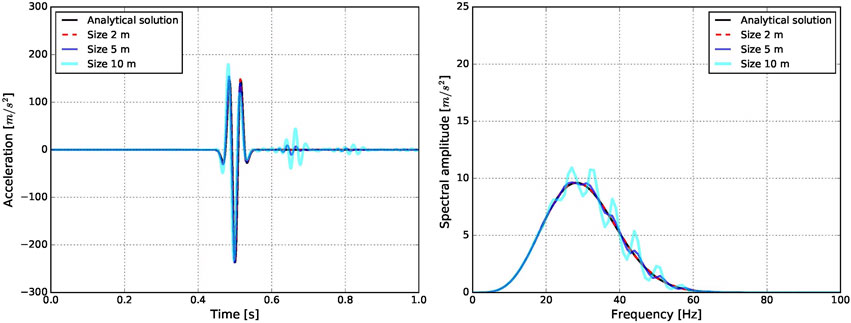
Figure 15. Verification of spatial discretization. Acceleration time series and spectra at point a of Figure 12A. Adopted from (Salamon and Jeremic, 2021).
4.4.5 Verification of fluid-structure interaction
To illustrate the fluid-structure interaction (FSI) between a rigid model of a concrete dam (or a wall in general) and its reservoir, the Westergaard exact (and also approximate) solution is compared with the results obtained from a finite element model, as described in (Salamon and Manie, 2017; Hariri-Ardebili et al., 2022b). This comparison, depicted in Figure 16, shows a good degree of correlation between the two approaches. Consequently, we can consider the finite element model verified against the analytical solution.
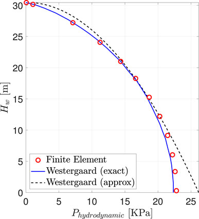
Figure 16. Comparison of hydrodynamic pressures calculated according to Westergaard’s exact and approximate formulas and the FE results for ground acceleration of 0.1 g. Adopted from (Salamon, 2015).
4.4.6 Verification of heat transfer
Thermal analysis is an integral part of the performance assessment of concrete dams. Thermal loads can induce significant stress gradients, especially in arch dams. The thermal analysis of dams involves various heat transfer mechanisms, including conduction, convection, and radiation. It is crucial to verify these heat transfer mechanisms using analytical models before applying them to real-world case studies.
For instance, the verification of heat conduction in a finite element package (which is the primary mechanism in concrete dams) can be performed using an analytical model for a semi-infinite solid, where one side of the surface is subjected to a periodic temperature variation
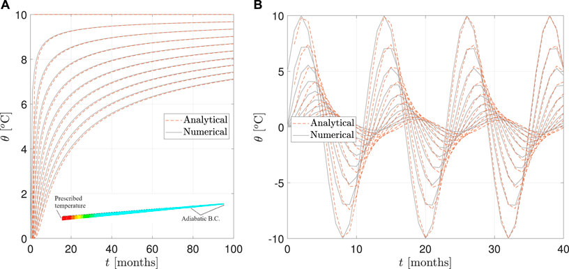
Figure 17. Verification of heat transfer in a semi-infinite beam with prescribed temperature at one end. Adopted from (Mahdavi, 2023). (A) Constant prescribed temperature. (B) Sinusoidal prescribed temperature.
4.4.7 Software-to-software comparison
The software-to-software comparison involves comparing the outputs of two or more software tools that are designed to solve similar engineering problems. This comparison aims to identify differences and similarities in the results produced by different software. There are several advantages to such a comparison. It helps to 1) benchmark software tools against each other, 2) identify discrepancies that might arise from different modeling approaches, numerical methods, or assumptions used in the software, and 3) ensure consistency and reliability of the results produced by different software tools.
An illustrative example of software-to-software comparison can be provided for the 18.2-m tall Stevenson Creek thin arch dam. In a study by Salamon and Robbe (2023), three finite element software packages–ADSAS, Code_Aster, and Diana FEA–were used to simulate the dam. Six different finite element models were prepared as follows (See Figure 18A): ADSAS with elastic foundation (M1), ADSAS with rigid foundation (M1-R), Code_Aster with solid elements (M2), Diana FEA with solid elements (M3), Diana FEA with shell elements and hinge BC (M4-H), and Diana FEA with shell elements and rigid BC (M4-R).
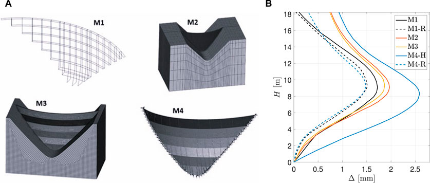
Figure 18. Comparing different finite element models of Stevenson Creek Dam using ADSAS with elastic foundation (M1), ADSAS with rigid foundation (M1-R), Code_Aster with solid elements (M2), Diana FEA with solid elements (M3), Diana FEA with shell elements and hinge BC (M4-H), and Diana FEA with shell elements and rigid BC (M4-R). (A) Finite element meshes. (B) Displacements of the central cantilever.
In all cases, the reservoir level was set at three-quarters of the dam height, and specific rock and concrete mechanical properties were used. Figure 18B illustrates the displacement variations along the central cantilever of the dam. As an outcome of this comparison, it can be observed that the general shape of the displacement curves is similar (with the maximum displacement occurring at about mid-height); however, variations in their magnitude are noted. These variations are attributed to:
• Type of analysis method implemented in the software: Trial Load Method (M1), solid FE formulation (M2 and M3), and shell FE formulation (M4).
• Model of foundation: rigid (M1R and M4R), elastic (M1, M2, and M3), and hinged (M4H).
• Spatial modeling: finite elements with linear (M3) and quadratic (M2) shape functions.
• Number of elements through the dam thickness: Three elements (M2) and six elements (M3).
An analysis of concrete dams using various software with different computational models helps identify the key elements that influence the accuracy of numerical solutions. As expected, the smallest displacement is obtained for the rigid foundation type, while the largest is for the hinged foundation type. For the elastic foundation, the M2 and M3 simulations (using solid elements) are in good agreement, and the difference in maximum displacement can be attributed to the type and size of the finite element mesh. An interesting observation can be made for the ADSAS results (M1), where the maximum displacement is within 10% of the M2 and M3 model results, but significant differences exist at the dam crest level.
5 Validation process
Validation is characterized as the process of assessing the degree to which a conceptual model is an accurate representation of the real world for physical phenomena it aims to simulate. This stage is pivotal, as it offers proof that the conceptual model chosen is appropriate and that model parameters are accurately determined.
In the context of concrete dam analysis, validation is typically conducted through the examination of experimental results, which includes field measurement data collected from actual dam structures and their components, alongside outcomes derived from laboratory model tests. This approach ensures that the simulations of concrete dams are grounded in empirical evidence, reflecting their real-world behavior and characteristics.
5.1 Types of experiments and sources of errors
5.1.1 Traditional experiments vs. validation experiments
Traditional experiments differ from validation experiments. Traditional experiments are primarily aimed at enhancing the understanding of physical processes, determining model parameter values, and evaluating system performance. These experiments are not specifically tailored to validate a conceptual model, as their design may not capture all necessary data with the precision required for validation purposes.
Validation experiments, in contrast, are precisely designed to produce high-quality data for directly assessing the accuracy of a conceptual model. They require precise construction and execution, focusing on capturing all essential characteristics needed for simulation. This includes highly accurate measurements of the system’s response to applied loads and comprehensive documentation of all test results.
A key challenge in using traditional experimental data for validation is the frequent lack of critical information, imprecise recording, or inadequate documentation. For validating computational models of concrete dams, essential data includes the actual geometry of the structure, specific mechanical material properties, spatial distribution of these properties, initial and boundary conditions, and the actual loads applied. The level of detail in test characteristics can range from deterministic data and precisely determined random values to estimations based on expert opinions or best judgments, all of which play a critical role in the validation process.
5.1.2 Sources of uncertainty and error in experiments
Uncertainty and error in experimental tests can stem from various sources, including variations in test fixtures, environmental conditions, testing equipment setups, and the accuracy of measurements. Errors during testing can arise from design tolerances, residual stresses, differences in test construction methods, and human errors.
Utilizing diverse testing equipment without appropriate calibration can lead to inconsistent observations, complicating the interpretation and utilization of the data for validation purposes in numerical simulations. An illustrative case involves the measurement of shear strength in alkali-aggregate reaction (AAR)-affected concrete specimens over a span of years (2004, 2010, 2014, 2021, and 2022). Notably, the testing equipment was updated to a more precise model for the last two assessments without calibrating the new equipment against the old. This change in testing procedures and equipment introduced significant uncertainty into the comparative analysis of data across the years, as detailed in the study by Lindenbach et al. (2022).
5.2 Hierarchy of validation experiments
In the process of validating models of concrete dams, a consistent approach is essential, progressing through different levels of complexity. This hierarchical strategy ensures a comprehensive understanding and validation of the dam models from the simplest elements to the entire system.
• Unit Problems: Focus on the fundamental features of the dam model, such as material properties and basic structural responses. For example, analyzing the tensile strength of concrete used in dam construction requires careful laboratory testing and comparison with established standards (e.g., ASTM C39 for compressive strength). This foundational level supports the accuracy of more complex simulations.
• Benchmark Problems: Entail comparing simulation outcomes with results from standardized problems with known solutions. These problems serve as a testbed to evaluate the model’s ability to replicate expected phenomena under well-defined conditions, like the fluid dynamics around a spillway or stress distribution in a gravity dam section under static loads. Reference to benchmark studies, such as those compiled by ICOLD (ICOLD Bulletin, 2024), provides a basis for cross-validation and model refinement.
• Subsystems: Involves validation of larger dam components that incorporate multiple unit problems, such as the interaction between the dam body and its foundation. This might include seismic response analysis of the dam-foundation system, requiring integration of geotechnical and structural simulation outcomes Bolzon et al. (2020).
• Complete System: The culmination of the validation process, assessing the model’s representation of the entire dam structure and its operational behavior Hall and Duron (2022). This encompasses the integration of all subsystems and their interactions under various operational scenarios, including overflow events, seismic activities, and foundation uplift pressures. Comprehensive system validations are challenging due to the scale and complexity, often relying on historical data, field measurements, and post-event analyses to benchmark the model’s predictive accuracy.
It’s recommended to conduct the first validation for unit problems, which are elemental parts of the complete systems under analysis. While unit and benchmark problems can typically be validated in a controlled laboratory environment, obtaining validation results for the entire systems or even subsystems is less common for concrete dam structures due to their complexity and scale.
5.3 Calibration process
In civil engineering, the calibration process involves tuning system parameters to enhance predictive accuracy and reliability. According to the ASME (ASME, 2006), calibration is described as the adjustment of physical modeling parameters in the computational model to improve agreement with experimental data.
Calibration typically involves aligning model predictions with actual experimental outcomes, and refining the model’s parameters until there’s a close correlation with observed data. This aims to reduce the discrepancy between the model’s predictions and real-world results. Various methods are employed in calibration, including scaling, normalization, and statistical approaches.
Scaling adjusts the data range, whereas normalization standardizes dataset values to a uniform scale, altering the distribution’s shape without compromising the variance in value ranges or information. Complex statistical calibration methods, such as isotonic regression, Platt scaling, or Bayesian binning into quantiles, are designed to fine-tune model-predicted probabilities to more accurately reflect observed probabilities.
Calibration is not only about improving the accuracy of model parameters but also about ensuring reliability and trustworthiness. A well-calibrated model provides more reliable predictions, which is crucial in real-world applications. Calibration is a continuous process, necessitating adjustments to models as new data emerges or if there’s a shift in the system’s operational performance. A thorough grasp and proper application of the calibration process are vital for fostering confidence in analytical outcomes.
For the structural analysis of dams, calibration involves leveraging experimental data from laboratory model tests or actual dam structures. This process may require fine-tuning various parameters, such as geometric dimensions, material properties, loads, boundary conditions, or specific computational model parameters, ensuring the model’s alignment with real-world conditions and behaviors.
Calibration of numerical models in concrete dams has been reported by Buffi et al. (2017) using dynamical measures for an arch-gravity dam, Fedele et al. (2006) for AAR assessment with inverse analysis, Sevieri et al. (2019) for static measurements in a gravity dam with Bayesian framework, Alves and Hall (2006); Hall and Duron (2022) for arch dams with a forced-vibration test, Cheng et al. (2016) for dynamic calibration based on strong-motion records, Daniell and Taylor (1999) for model calibration with ambient testing, Mirzabozorg et al. (2014) for thermal and static model calibration of an arch dam, etc.
5.4 Demonstrating validation process for concrete dams
The field of concrete dam engineering pioneered the comprehensive and systematic assessment of computational methods. Led by the efforts of Reclamation, the dam engineering community in the USA acknowledged at the beginning of the 20th century the complexities in calculating internal forces and deformations within arch dams (Max and Noetzli, 1927; Savage et al., 1931a; Fuller and Flinn, 1933). Recognizing the importance of computational method accuracy, they deemed it essential to ensure confidence in these results before integrating such approaches into standard design practices. This narrative is supported by Tarbox et al. (2020), who discusses the industry’s early commitment to methodological precision. Initiated in the 1920s, an extensive investigative program bolstered designer confidence, facilitating the adoption of Trial Load Methods for the structural analysis and design of both arch and gravity dams within engineering practices. Central to this program was:
• Comparing various analysis methods: This involved a comparative study of the different structural analysis methods available at the time for arch dams.
• Testing of a large-scale thin arch experimental dam: An 18.2-m-high experimental structure was constructed specifically to validate the Trial-Load approach, as documented in Max and Noetzli (1927).
• Conducting laboratory model tests: Laboratory tests for models of Stevenson Creek Dam and Gibson Dam were carried out at the University of Colorado at Boulder (Savage et al., 1931b).
• Monitoring the construction of concrete arch dams: In the 1920s and 1930s, the construction of several arch dams was closely monitored, providing real-world insights and data critical for validating and refining analysis methods (Fuller and Flinn, 1933; Savage et al., 1931a).
The efforts undertaken for the Trial Load Method represent what would now be recognized as the pioneering validation procedure in engineering practice, despite such terminology not being used at the time. Gaining satisfactory confidence in the Trial Load Method paved the way for its successful application in the design of several dams for more than 50 years until the finite element method emerged as the prevalent computational analysis tool for concrete dams in the 1980s.
Since then, the engineering community, including various organizations and academic institutions, has developed multiple validation tests and established benchmarks to validate analysis methods for concrete dams. These efforts have been documented in various sources, reflecting the continuous evolution and refinement of validation processes within the field (Rijkswaterstaat, 2017; Fry and Matsumoto, 2018; Saouma and Hariri-Ardebili, 2021a; Ghanaat et al., 2024; ICOLD Bulletin, 2024 in-progress).
5.4.1 Validation with laboratory tests
In this section, we discuss a selection of laboratory case studies that have played a crucial role in the validation of computational models.
Koyna Dam in India, subjected to a magnitude 6.5 earthquake in 1967, stands as a significantly studied example of dams affected by seismic activity. Various researchers have undertaken laboratory tests to explore the reasons behind the dam’s failure during this event. A primary aim of these shaking tests, conducted on laboratory models, was to validate computational models. Niwa and Clough (1980), as well as the Bureau of Reclamation (Reclamation, 1999b; b; Harris et al., 2000) carried out experiments on 1:50 scale models. Concurrently, the U.S. Army Corps of Engineers (USACE) conducted tests on 1:20 scale models of concrete gravity sections (Norman et al., 1986; Wilcoski et al., 2001). These small-scale tests by USACE utilized sinusoidal motions close to the model’s natural frequency, aiming to replicate the conditions experienced by Koyna Dam during the earthquake.
The computational model’s validation process, utilizing the test results from a 1:40 scale laboratory model of the Carpinteri Gravity Dam under static loads, is elaborated by Ribeiro and Léger (2023). This study primarily examined the dam’s cracking behavior, building on the original experiments conducted by Carpinteri et al. (2003). The model, a structure with a height of 2.4 m and base and crest lengths of 2.0 and 0.248 m respectively, features a small upstream slope of 3% and a steep downstream slope of 70%. Unlike some models, this one does not have a neck. The model’s base is fixed, with horizontal loads applied at four points along its upstream height. Notably, there is a notch on the upstream face, positioned 0.6 m above the base, which is 20 mm thick and extends 150 mm into the dam, with the model itself having an out-of-plane thickness of 300 mm. This detailed study offers insights into the structural responses and potential failure modes of gravity dams subjected to static loading conditions. In the study by Ribeiro and Léger (2023), they summarized the results of different modeling strategies including concrete damage model, boundary condition, particle or meshfree methods, among others on the load-crack mouth opening displacement, and crack trajectory. They also investigated different mesh types, sizes, elements, interactions, and solver options.
Different researchers have used this benchmark model with either discrete crack (Valente and Barpi, 1970; Barpi and Valente, 2000; Shi et al., 2003; Wu et al., 2013) or smeared crack (Bhattacharjee and Leger, 1994; Ghrib and Tinawi, 1995; Mirzabozorg and Ghaemian, 2005; Hariri-Ardebili et al., 2013; Wang et al., 2015b; Roth et al., 2015; Dias et al., 2016) models.
5.4.2 Validation with field tests
The validation of analytical results for concrete dams has been extensively explored through seventeen benchmark workshops organized by the ICOLD Committee on Computational Aspects of Analysis and Design of Dams. Since the inception of these workshops in 1991, a diverse array of 26 themes pertinent to concrete dams has been addressed. The comprehensive case studies derived from these themes are documented in the ICOLD Bulletin (ICOLD Bulletin, 2024 in-progress), serving as a valuable resource for understanding the outcomes of these benchmarks.
To exemplify the validation process in the context of actual dam structures, two specific cases are highlighted: the Stevenson Creek Experimental Dam and Pine Flat Dam.
The 18.2-m tall Stevenson Creek arch dam, built and tested in 1926, was designed exclusively to validate the Trial Load Method for structural analysis. The positive outcome of this experiment led to the method’s acceptance in the design practice of concrete arch dams (Max and Noetzli, 1927; Tarbox et al., 2020).
Comparison of the results for Stevenson Creek Dam obtained with various software is presented in Section 4.4 – Software-to-Software Comparison. The calibration of parameters and validation process of the analysis results using the Stevenson Creek Dam field measurement data, as presented by Salamon and Robbe (2023), are briefly discussed. In model parameter calibration, the elastic modulus of concrete and the elastic modulus of rock mass were identified as the key parameters that most affect the analysis results. The goal of the calibration process was to match the maximum computed displacement at the dam’s central cantilever with the measurement data. It was achieved by lowering the elastic modulus of concrete from 20 GPa, used in comparison analysis for the “base case” in Section 4.4, to 15 GPa (see Figure 19). However, significant disagreement in computed and measured displacements is observed at the dam crest that could be caused by various reasons, including errors in measurements or a special feature in the dam not considered in the conceptual model.
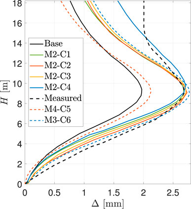
Figure 19. Comparison of measured displacements at the central cantilever of Stevenson Creek Dam with analysis results obtained by various software after parameter calibration (Salamon and Robbe, 2023). The definition of models is provided in Section 4.4.
Although Pine Flat Dam was not built for validation purposes, it has been extensively investigated by many engineers and researchers, including Rea et al. (1972); Asteris and Tzamtzis (2003); Løkke and Chopra (2013). It was also selected as a case study for the USSD (Salamon, 2018) and ICOLD (Salamon et al., 2021) benchmark studies. The field testing results have become a valuable source of information used in the validation process of various analytical tools.
Experimental tests conducted on the Pine Flat Dam in 1971 provide a basis for numerical analysis validation (Rea et al., 1972). The natural frequencies obtained from the EMVG test at the site were used as reference data in the 15th ICOLD benchmark studies (Salamon et al., 2021). The test covers modes #2, #3, and #6 for both summer and winter water levels. Modes #2 and #3 can be described as the first and second bending modes of the entire dam, while mode #6 can be described as the fourth bending mode. Figure 20 (left) shows the mode shapes from the EMVG test, while the plots on the right are global mode shapes for the entire dam reported by Rea et al. (1972).
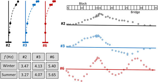
Figure 20. Mode shapes for Pine Flat Dam used for model validation (Rea et al., 1972).
5.4.3 Validation with both laboratory and field tests
In some cases, the validation process needs to be implemented at both the component level (including both material and structural models) and the system level (the entire dam). This is often necessary for analyzing concrete degradation due to factors such as AAR, creep, shrinkage, and freeze-thaw cycles.
For example, in the case of AAR, a series of validation problems have been identified in Saouma et al. (2021), with several of these completed by various groups (Saouma and Hariri-Ardebili, 2021a; Morenon et al., 2021; Nedjar et al., 2021; Roth, 2021). A notable example of combined laboratory and field tests for AAR validation can be found in (Saouma and Perotti, 2006; Saouma et al., 2007). This includes component-level validation through laboratory tests on 130-by-240 mm concrete specimens cast inside steel cylinders and subjected to 0 (free), 10, or 20 MPa compressive stresses. Figure 21A illustrates the comparison of free AAR expansion in both longitudinal and transversal directions for tests and finite element simulations. The right side of the figure shows the transversal AAR expansion under two different confined conditions. In all cases, the simulations accurately capture the test results.
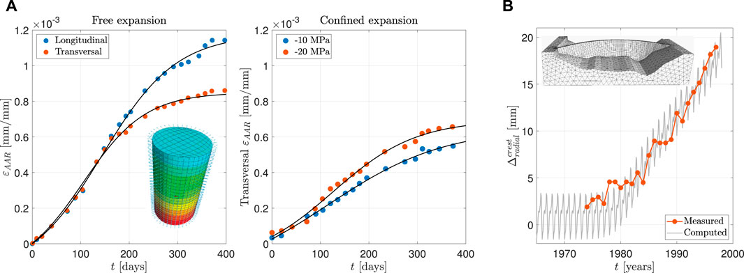
Figure 21. Samples results from AAR expansion validation for concrete dams in component- and system-level using both the laboratory test and field measurement data. (A) Component-level concrete cylinder expansion inside a steel cage. (B) System-level concrete dam expansion.
The same validated AAR model is also used to predict AAR expansion in an arch-gravity dam. Isola Dam, which is 45 m high with a 5-m crest width and a 22-m base width, serves as a case study. Through a series of system identifications and validations, the crest radial displacement has been compared to field measurements, as shown in Figure 21B. Simulations conducted using the finite element package Merlin indicate that the computed displacement follows the general trend of the field measurements. Such validated models can be used to predict future expansion, potential damage, and to estimate the residual lifespan of the dam.
6 Concluding remarks
Modeling and simulation are essential tools in structural condition assessments used in safety evaluation for concrete dams. Appraising accuracy of the solution and estimating uncertainties in the results are primary concerns in building confidence in analysis outcomes, but V&V processes are crucial tools for establishing such confidence.
This paper presents a road map for conducting structural analysis of concrete dams, along with key terminology related to the verification and validation process. General guidelines for implementing the verification, validation, and uncertainty quantification procedures are provided and illustrated through selected case studies of concrete dams.
It is important to emphasize that computational methods and commercial software need to be verified by engineers and analysts before being used in the structural analysis of dams. Relying on the code developer’s quality assurance and quality control process is not sufficient before the software is used in the engineering practice. The authors outline a path and practical recommendations for verifying computational models and software. Key conclusions of this study include:
• Verification should always precede validation to prevent the accumulation of errors within conceptual models and the verification process.
• Using proper and precise terminology in discussions about V&V and UQ is crucial to avoid communication issues.
• Validation experiments should be precisely designed and prepared to produce high-quality data that capture all essential characteristics needed for modeling and simulation. For many existing dams, complete construction documentation, comprehensive project data, or precise measurements may not exist, which can affect the outcomes of validation studies.
• Uncertainty quantification is important in understanding the reliability and robustness of simulation results. Properly quantifying uncertainties helps in identifying the key parameters that influence the analysis results and guides efforts to improve model accuracy and reliability.
• Verification and validation are key processes in building confidence in analysis results.
• Successful verification and validation for one physical structure do not guarantee the same outcome for another structure.
• Expert opinion is a key factor in building confidence in the results of dam analysis.
Although this paper may not address all aspects related to the V&V and UQ process for analyzing concrete dams, it contributes to the discussion on developing unified guidelines for the V&V process in application to structural analyses of concrete dams. These guidelines would focus on establishing accuracy, credibility, and confidence in modeling and simulation results used for dam safety risk estimations and supporting policy decisions for potential modifications.
Advanced analysis techniques currently used in structural assessments of existing dams and the design of new dams also require evaluation of their efficiency, reliability, and validity. Engineering judgment and proper interpretation of the results are important components in building confidence in analysis results.
The importance of the V&V and UQ process in building confidence in and assessing the accuracy of analysis results cannot be overstated. With significant reliance on modeling and simulation for design, condition assessment, and regulatory work, detailed V&V efforts need to be developed and documented. Recent USSD, ICOLD, and the authors’ publications on the subject have provided useful initial results. However, there is a need to develop a systematic approach and plan for establishing V&V and UQ for the analysis of concrete dams, which can be implemented into engineering practice.
Future contributions will focus on developing a White Paper in collaboration with the USSD’s Subcommittee on the Analysis of Concrete Dams. This effort can be expanded by involving an international engineering community in preparation of a new ICOLD bulletin and formulating new benchmark problems for the USSD and ICOLD engineering community in a systematic way, following principles of validation experiments. Additionally, the proposed systematic framework can be implemented across various classes of concrete dams, including gravity, arch, arch-gravity, and buttress dams, as well as embankments.
Data availability statement
The raw data supporting the conclusions of this article will be made available from the corresponding author upon reasonable request.
Author contributions
JWS: Conceptualization, Data curation, Formal Analysis, Funding acquisition, Investigation, Methodology, Project administration, Resources, Software, Supervision, Validation, Visualization, Writing–original draft, Writing–review and editing. MAH-A: Conceptualization, Data curation, Formal Analysis, Funding acquisition, Investigation, Methodology, Project administration, Resources, Software, Supervision, Validation, Visualization, Writing–original draft, Writing–review and editing.
Funding
The author(s) declare that financial support was received for the research, authorship, and/or publication of this article. This research was financially supported by the Dam Safety Office, through the Dam Safety and Infrastructure Technology Development Program, DSO-2023-02, at the U.S. Bureau of Reclamation.
Acknowledgments
The first author would like to acknowledge the Dam Safety Office at the U.S. Bureau of Reclamation for the support of this research. The authors would like to express their gratitude to Professor Boris Jeremić of the University of California, Davis, for his fruitful discussion and invaluable assistance in key aspects of this research.
Conflict of interest
The authors declare that the research was conducted in the absence of any commercial or financial relationships that could be construed as a potential conflict of interest.
The author(s) declared that they were an editorial board member of Frontiers, at the time of submission. This had no impact on the peer review process and the final decision.
Publisher’s note
All claims expressed in this article are solely those of the authors and do not necessarily represent those of their affiliated organizations, or those of the publisher, the editors and the reviewers. Any product that may be evaluated in this article, or claim that may be made by its manufacturer, is not guaranteed or endorsed by the publisher.
References
AIAA (1998). “Guide for the verification and validation of computational fluid dynamics simulations,” in American Institute of Aeronautics and Astronautics, Computational Fluid Dynamics Committee, AIAA G-077-1998, 2002. Tech. rep.
Alembagheri, M. (2018). Investigating efficiency of vector-valued intensity measures in seismic demand assessment of concrete dams. Adv. Civ. Eng. 2018, 1–12. doi:10.1155/2018/5675032
Alembagheri, M., and Ghaemian, M. (2013a). Incremental dynamic analysis of concrete gravity dams including base and lift joints. Earthq. Eng. Eng. Vib. 12, 119–134. doi:10.1007/s11803-013-0156-2
Alembagheri, M., and Ghaemian, M. (2013b). Seismic assessment of concrete gravity dams using capacity estimation and damage indexes. Earthq. Eng. Struct. Dyn. 42, 123–144. doi:10.1002/eqe.2196
Alembagheri, M., and Ghaemian, M. (2013c). Damage assessment of a concrete arch dam through nonlinear incremental dynamic analysis. Soil Dyn. Earthq. Eng. 44, 127–137. doi:10.1016/j.soildyn.2012.09.010
Alembagheri, M., and Ghaemian, M. (2016). Seismic performance evaluation of a jointed arch dam. Struct. Infrastructure Eng. 12, 256–274. doi:10.1080/15732479.2015.1009124
Altarejos-Garcia, L., Escuder-Bueno, I., and Morales-Torres, A. (2015). Advances on the failure analysis of the dam—foundation interface of concrete dams. Materials 8, 8255–8278. doi:10.3390/ma8125442
Alves, S., and Hall, J. (2006). System identification of a concrete arch dam and calibration of its finite element model. Earthq. Eng. and Struct. Dyn. 35, 1321–1337. doi:10.1002/eqe.575
Amini, A., Abdollahi, A., and Hariri-Ardebili, M. A. (2024). An automated machine-learning-assisted stochastic-fuzzy multi-criteria decision making tool: addressing record-to-record variability in seismic design. Appl. Soft Comput. 154, 111354. doi:10.1016/j.asoc.2024.111354
Ang, A. H. S. (1970). Extended reliability basis of structural design under uncertainties. Tech. Rep. SAE Tech. Pap., 700656. doi:10.4271/700656
Ang, A. H. S., and Tang, W. H. (2007). Probability concepts in engineering planning and design: emphasis on application to civil and environmental engineering. Wiley.
Aslani, H., and Miranda, E. (2005). Probabilistic earthquake loss estimation and loss disaggregation in buildings. Stanford, Palo-Alto, CA: Stanford University. Ph.D. thesis.
ASME (2006). Guide for verification and validation in computational solid mechanics. American Society of Mechanical Engineers. Tech. rep. Refirmed 2016.
ASME (2009). Standard for verification and validation in computational fluid dynamics and heat transfer V&V 20 - 2009(r2016). American Society of Mechanical Engineers. Tech. rep ISBN: 9780791832097.
ASME (2019). Standard for verification and validation in computational solid mechanics, V&V 10 - 2019. American Society of Mechanical Engineers. Tech. rep. ISBN: 9780791873168.
Asteris, P., and Tzamtzis, A. (2003). Nonlinear seismic response analysis of realistic gravity dam-reservoir systems. Int. J. Nonlinear Sci. Numer. Simul. 4, 329–338. doi:10.1515/ijnsns.2003.4.4.329
Ayyub, B. M., and Chao, R. (1997). “Uncertainty modeling in civil engineering with structural and reliability applications,” in Uncertainty modeling and analysis in civil engineering, 1–8.
Babuška, I., and Oden, J. T. (2004). Verification and validation in computational engineering and science: basic concepts. Comput. Methods Appl. Mech. Eng. 193, 4057–4066. doi:10.1016/j.cma.2004.03.002
Barbato, M., Gu, Q., and Conte, J. (2010). Probabilistic push-over analysis of structural and soil-structure systems. J. Struct. Eng. 136, 1330–1341. doi:10.1061/(asce)st.1943-541x.0000231
Barpi, F., and Valente, S. (2000). Numerical simulation of prenotched gravity dam models. J. Eng. Mech. 126, 611–619. doi:10.1061/(asce)0733-9399(2000)126:6(611)
Bathe, K. J., and Cimento, A. P. (1980). Some practical procedures for the solution of nonlinear finite element equations. Comput. methods Appl. Mech. Eng. 22, 59–85. doi:10.1016/0045-7825(80)90051-1
Bažant, Z. P., and Planas, J. (2019). Fracture and size effect in concrete and other quasibrittle materials. New York: Routledge. doi:10.1201/9780203756799
Bhattacharjee, S., and Leger, P. (1994). Application of nlfm models to predict cracking in concrete gravity dams. ASCE Struct. Eng. 120, 1255–1271. doi:10.1061/(asce)0733-9445(1994)120:4(1255)
Bolzon, G., Sterpi, D., Mazzà, G., and Frigerio, A. (2020). “Numerical analysis of dams,” in Proceedings of the 15th ICOLD international benchmark workshop (Springer Nature), 91.
Bradley, B. A. (2011). A framework for validation of seismic response analyses using seismometer array recordings. Soil Dyn. Earthq. Eng. 31, 512–520. doi:10.1016/j.soildyn.2010.11.008
Bradley, B. A. (2013). A critical examination of seismic response uncertainty analysis in earthquake engineering. Earthq. Eng. and Struct. Dyn. 42, 1717–1729. doi:10.1002/eqe.2331
British Army (1947). Operational research in the British army 1939–1945. Report C67/3/4/48, UK44 National Archives file WO291/1301.
Buffi, G., Manciola, P., De Lorenzis, L., Cavalagli, N., Comodini, F., Gambi, A., et al. (2017). Calibration of finite element models of concrete arch-gravity dams using dynamical measures: the case of ridracoli. Procedia Eng. 199, 110–115. doi:10.1016/j.proeng.2017.09.169
Bulleit, W. M. (2008). Uncertainty in structural engineering. Pract. Periodical Struct. Des. Constr. 13, 24–30. doi:10.1061/(asce)1084-0680(2008)13:1(24)
Buonopane, S. G. (2008). Strength and reliability of steel frames with random properties. J. Struct. Eng. 134, 337–344. doi:10.1061/(asce)0733-9445(2008)134:2(337)
Bybordiani, M., and Arıcı, Y. (2017). The use of 3d modeling for the prediction of the seismic demands on the gravity dams. Earthq. Eng. and Struct. Dyn. 46, 1769–1789. doi:10.1002/eqe.2880
Calcina, S. V., Eltrudis, L., Piroddi, L., and Ranieri, G. (2014). Ambient vibration tests of an arch dam with different reservoir water levels: experimental results and comparison with finite element modelling. Sci. World J. 2014, 1–12. doi:10.1155/2014/692709
Cantieni, R. (2001). “Assessing a dam’s structural properties using forced vibration testing,” in Proc. IABSE international conference on safety, risk and reliability-trends in engineering (Malta).
Carpinteri, A., Valente, S., Ferrara, G., and Imperato, L. (2003). “Experimental and numerical fracture modelling of a gravity dam,” in Fracture Mechanics of Concrete Structures. CRC Press, 351–360.
Cedolin, L., and Bazant, Z. P. (2010). Stability of structures: elastic, inelastic, fracture and damage theories (World Scientific).
Celik, O., and Ellingwood, B. (2010). Seismic fragilities for non-ductile reinforced concrete frames–role of aleatoric and epistemic uncertainties. Struct. Saf. 32, 1–12. doi:10.1016/j.strusafe.2009.04.003
Cervera, M., and Chiumenti, M. (2006). Smeared crack approach: back to the original track. Int. J. Numer. Anal. Methods Geomechanics 30, 1173–1199. doi:10.1002/nag.518
Chanson, H., and James, P. (1998). Rapid reservoir sedimentation of four historic thin arch dams in Australia. J. Perform. Constr. Facil. 12, 85–92. doi:10.1061/(asce)0887-3828(1998)12:2(85)
Charmpis, D. C. (2019). The effect of correlations among random member properties on structural reliability. Structures 19, 463–475. doi:10.1016/j.istruc.2019.02.002
Chen, D. H., Yang, Z. H., Wang, M., and Xie, J. H. (2019). Seismic performance and failure modes of the jin’anqiao concrete gravity dam based on incremental dynamic analysis. Eng. Fail. Anal. 100, 227–244. doi:10.1016/j.engfailanal.2019.02.018
Chen, J., and Wan, Z. (2019). A compatible probabilistic framework for quantification of simultaneous aleatory and epistemic uncertainty of basic parameters of structures by synthesizing the change of measure and change of random variables. Struct. Saf. 78, 76–87. doi:10.1016/j.strusafe.2019.01.001
Chen, S., Gu, C., Lin, C., and Hariri-Ardebili, M. A. (2021). Prediction of arch dam deformation via correlated multi-target stacking. Appl. Math. Model. 91, 1175–1193. doi:10.1016/j.apm.2020.10.028
Chen, S., Gu, C., Lin, C., Wang, Y., and Hariri-Ardebili, M. A. (2020). Prediction, monitoring, and interpretation of dam leakage flow via adaptative kernel extreme learning machine. Measurement 166, 108161. doi:10.1016/j.measurement.2020.108161
Cheng, L., Yang, J., Zheng, D., Tong, F., and Zheng, S. (2016). The dynamic finite element model calibration method of concrete dams based on strong-motion records and multivariate relevant vector machines. J. Vibroengineering 18, 3811–3828. doi:10.21595/jve.2016.16953
Chopra, A. K. (2020). Earthquake engineering for concrete dams: analysis, design, and evaluation. John Wiley and Sons.
Chowdhury, M., Matheu, E., and Hall, R. (2001). “Shake table experiment of a 1/20-scale Koyna dam model,” in Proceedings of the 19th International Modal Analysis Conference, IMAC XIX (Orlando, FL, USA).
Comi, C., Fedele, R., and Perego, U. (2009). A chemo-thermo-damage model for the analysis of concrete dams affected by alkali-silica reaction. Mech. Mater. 41, 210–230. doi:10.1016/j.mechmat.2008.10.010
Cremona, C. (2003). Probabilistic approach for cable residual strength assessment. Eng. Struct. 25, 377–384. doi:10.1016/s0141-0296(02)00173-6
Daniell, W., and Taylor, C. (1999). Effective ambient vibration testing for validating numerical models of concrete dams. Earthq. Eng. and Struct. Dyn. 28, 1327–1344. doi:10.1002/(sici)1096-9845(199911)28:11<1327::aid-eqe869>3.3.co;2-m
Darbre, G., De Smet, C., and Kraemer, C. (2000). Natural frequencies measured from ambient vibration response of the arch dam of mauvoisin. Earthq. Eng. and Struct. Dyn. 29, 577–586. doi:10.1002/(sici)1096-9845(200005)29:5<577::aid-eqe924>3.0.co;2-p
Der-Kiureghian, A., and Ditlevsen, O. (2009). Aleatory or epistemic? does it matter? Struct. Saf. 31, 105–112. doi:10.1016/j.strusafe.2008.06.020
Dias, I., Oliver, J., Lemos, J., and Lloberas-Valls, O. (2016). Modeling tensile crack propagation in concrete gravity dams via crack-path-field and strain injection techniques. Eng. Fract. Mech. 154, 288–310. doi:10.1016/j.engfracmech.2015.12.028
Díaz, S. A., Pujades, L. G., Barbat, A. H., Hidalgo-Leiva, D. A., and Vargas-Alzate, Y. F. (2018). Capacity, damage and fragility models for steel buildings: a probabilistic approach. Bull. Earthq. Eng. 16, 1209–1243. doi:10.1007/s10518-017-0237-0
DoD (1994). Modeling and simulation (M&S) management, Directive No. 5000.59. US Department of Defense.
Ebeling, R. M., Green, R. A., and French, E. S. (1997). “Accuracy of response of single-degree-of-freedom systems to ground motion,” in USACE TR ITL-97-7, Department of the Army (Washington D.C., USA: U.S. Army Corps of Engineers). Tech. Rep.
Ebrahimi, E., Abdollahzadeh, G., and Jahani, E. (2020). Developing the seismic fragility analysis with fuzzy random variables using mouth brooding fish algorithm. Appl. Soft Comput. 91, 106190. doi:10.1016/j.asoc.2020.106190
Ellingwood, B. (1998). Issues related to structural aging in probabilistic risk assessment of nuclear power plants. Reliab. Eng. and Syst. Saf. 62, 171–183. doi:10.1016/s0951-8320(98)00018-0
Elnashai, A. S., and Chryssanthopoulos, M. (1991). Effect of random material variability on seismic design parameters of steel frames. Earthq. Eng. and Struct. Dyn. 20, 101–114. doi:10.1002/eqe.4290200202
Fedele, R., Maier, G., and Miller, B. (2006). Health assessment of concrete dams by overall inverse analyses and neural networks. Int. J. Fract. 137, 151–172. doi:10.1007/s10704-006-6582-7
Fenves, G., and Chopra, A. (1985). Simplified earthquake analysis of concrete gravity dams: separate hydrodynamic and foundation interaction effects. J. Eng. Mech. 111, 715–735. doi:10.1061/(asce)0733-9399(1985)111:6(715)
FERC (1999). Engineering guidelines for the evaluation of hydropower projects: chapter 11: arch dams. Washington, DC, USA: Federal Energy Regulatory Commission. Tech. rep.
Fry, J. J., and Matsumoto, N. (2018). “Validation of dynamic analyses of dams and their equipment,” in Contributions to the international symposium on the qualification of dynamic analyses of dams and their equipments, 31 august-2 september 2016 (Saint-Malo. France: CRC Press).
Fuller, G. W., and Flinn, A. D. (1933). “Arch dam investigation,” in Engineering Foundation Committee Joint Research Organizatin of the American Society of Civil Engineers, American Institure of Mining and Metallugical Engineers, the American Society of Mechannical Engineers, Americna Institue of Elelctrical Engineers Denver Colorado. Tech. rep.
Ghanaat, Y., Harper, Z., and Han, Z. (2024). “A validation framework for linear and nonlinear dam safety analysis techniques,” in Proceeding of the the 18th World Conference on Earthquake Engineering (Milan, Italy).
Ghrib, F., and Tinawi, R. (1995). Nonlinear behavior of concrete dams using damage mechanics. J. Eng. Mech. 121, 513–527. doi:10.1061/(asce)0733-9399(1995)121:4(513)
Gomes, J. P., and Lemos, J. V. (2020). Characterization of the dynamic behavior of a concrete arch dam by means of forced vibration tests and numerical models. Earthq. Eng. and Struct. Dyn. 49, 679–694. doi:10.1002/eqe.3259
Gorai, S., and Maity, D. (2023). Seismic fragility assessment of concrete gravity dams under near source synthetic ground motions. Struct. Infrastructure Eng., 1–21. doi:10.1080/15732479.2023.2207168
Graham, L., and Deodatis, G. (2001). Response and eigenvalue analysis of stochastic finite element systems with multiple correlated material and geometric properties. Probabilistic Eng. Mech. 16, 11–29. doi:10.1016/s0266-8920(00)00003-5
Grigoriu, M., and Turkstra, C. (1979). Safety of structural systems with correlated resistances. Appl. Math. Model. 3, 130–136. doi:10.1016/0307-904x(79)90040-4
Hall, R., and Duron, Z. (2022). “Performance based testing and analysis of Mossyrock Dam,” in Center for energy advancement through technological innovation. Tech. rep CEATI Project T202700-0250.
Hariri-Ardebili, M. A. (2020). Uncertainty quantification of heterogeneous mass concrete in macro-scale. Soil Dyn. Earthq. Eng. 137, 106137. doi:10.1016/j.soildyn.2020.106137
Hariri-Ardebili, M. A. (2024). Quantifying modeling uncertainties in seismic analysis of dams: insights from an international benchmark study. Earthq. Eng. and Struct. Dyn. 53, 1168–1194. doi:10.1002/eqe.4064
Hariri-Ardebili, M. A., Chen, S., and Mahdavi, G. (2022a). Machine learning-aided psdm for dams with stochastic ground motions. Adv. Eng. Inf. 52, 101615. doi:10.1016/j.aei.2022.101615
Hariri-Ardebili, M. A., Furgani, L., Meghella, M., and Saouma, V. (2016a). A new class of seismic damage and performance indices for arch dams via eta method. Eng. Struct. 110, 145–160. doi:10.1016/j.engstruct.2015.11.021
Hariri-Ardebili, M. A., Mahdavi, G., Nuss, L. K., and Lall, U. (2023). The role of artificial intelligence and digital technologies in dam engineering: narrative review and outlook. Eng. Appl. Artif. Intell. 126, 106813. doi:10.1016/j.engappai.2023.106813
Hariri-Ardebili, M. A., Poul, M. K., Nikolaou, S., and Zerva, A. (2024). Deconvolved intensifying artificial accelerations (diaa): theory and application in geostructures. Comput. Geotechnics 170, 106291. doi:10.1016/j.compgeo.2024.106291
Hariri-Ardebili, M. A., and Pourkamali-Anaraki, F. (2022). An automated machine learning engine with inverse analysis for seismic design of dams. Water 14, 3898. doi:10.3390/w14233898
Hariri-Ardebili, M. A., Salamon, J. W., and Seyed-Kolbadi, S. M. (2022b). Discussion of “hydrodynamic pressure on gravity dams with different heights and the Westergaard correction formula” by mingming wang, jianyun chen, liang Wu, and bingyue song. Int. J. Geomechanics 22, 07022006. doi:10.1061/(asce)gm.1943-5622.0002396
Hariri-Ardebili, M. A., and Saouma, V. (2015). Quantitative failure metric for gravity dams. Earthq. Eng. Struct. Dyn. 44, 461–480. doi:10.1002/eqe.2481
Hariri-Ardebili, M. A., and Saouma, V. (2016a). Probabilistic seismic demand model and optimal intensity measure for concrete dams. Struct. Saf. 59, 67–85. doi:10.1016/j.strusafe.2015.12.001
Hariri-Ardebili, M. A., and Saouma, V. (2016b). Seismic fragility analysis of concrete dams: a state-of-the-art review. Eng. Struct. 128, 374–399. doi:10.1016/j.engstruct.2016.09.034
Hariri-Ardebili, M. A., and Saouma, V. (2016c). Sensitivity and uncertainty quantification of the cohesive crack model. Eng. Fract. Mech. 155, 18–35. doi:10.1016/j.engfracmech.2016.01.008
Hariri-Ardebili, M. A., Saouma, V., and Porter, K. (2016b). Quantification of seismic potential failure modes in concrete dams. Earthq. Eng. Struct. Dyn. 45, 979–997. doi:10.1002/eqe.2697
Hariri-Ardebili, M. A., and Seyed-Kolbadi, S. (2015). Seismic cracking and instability of concrete dams: smeared crack approach. Eng. Fail. Anal. 52, 45–60. doi:10.1016/j.engfailanal.2015.02.020
Hariri-Ardebili, M. A., Seyed-Kolbadi, S., and Mirzabozorg, H. (2013). A smeared crack model for seismic failure analysis of concrete gravity dams considering fracture energy effects. Struct. Eng. Mech. 48, 17–39. doi:10.12989/sem.2013.48.1.017
Hariri-Ardebili, M. A., Seyed-Kolbadi, S., Saouma, V., Salamon, J., and Nuss, L. (2019). Anatomy of the vibration characteristics in old arch dams by random field theory. Eng. Struct. 179, 460–475. doi:10.1016/j.engstruct.2018.10.082
Hariri-Ardebili, M. A., Seyed-Kolbadi, S., Saouma, V., Salamon, J., and Rajagopalan, B. (2018). Random finite element method for the seismic analysis of gravity dams. Eng. Struct. 171, 405–420. doi:10.1016/j.engstruct.2018.05.096
Harris, D. W., Snorteland, N., Dolen, T., and Travers, F. (2000). Shaking table 2-d models of a concrete gravity dam. Earthq. Eng. and Struct. Dyn. 29, 769–787. doi:10.1002/(sici)1096-9845(200006)29:6<769::aid-eqe925>3.3.co;2-z
Haselton, C., and Deierlein, G. (2006). Assessing seismic collapse safety of modern reinforced concrete moment frame buildings, report no 2007/08. John A. Blume Earthquake Engineering Center Department of Civil Engineering. Tech. rep., TR 156.
Helton, J. C. (1994). Treatment of uncertainty in performance assessments for complex systems. Risk Anal. 14, 483–511. doi:10.1111/j.1539-6924.1994.tb00266.x
Helton, J. C., Johnson, J. D., Oberkampf, W. L., and Sallaberry, C. J. (2010). Representation of analysis results involving aleatory and epistemic uncertainty. Int. J. General Syst. 39, 605–646. doi:10.1080/03081079.2010.486664
ICOLD Bullet (2013). “Guidelines for use of numerical models in dam engineering,” in International Commission on Large Dams, the Committee on Computational Aspects of Analysis and Design of Dams. Tech. rep.
ICOLD Bulletin (1994). “Computer software for dams - validation,” in International Commission on Large Dams, the Committee on Computational Aspects of Analysis and Design of Dams. Tech. rep.
ICOLD Bulletin (2001). “Computational procedures for dam engineering,” in International Commission on Large Dams, The Committee on Computational Aspects of Analysis and Design of Dams. Tech. rep.
ICOLD Bulletin (2024). “Capitalization of the results related to benchmark workshops on numerical modelling,” in International Commission on Large Dams, Committee Computational Aspects of Analysis and Design of Dams. In-progress. Tech. rep.
ISO (2018). ISO/IEC/IEEE 90003, Software engineering – guidelines for the application of ISO 9001:2015 to computer software. International Organization for Standardization. Tech. rep.
Jackson, D. C. (2005). Building the ultimate dam: John S. Eastwood and the control of water in the West. University of Oklahoma Press.
Jalayer, F., and Cornell, C. (2009). Alternative non-linear demand estimation methods for probability-based seismic assessments. Earthq. Eng. Struct. Dyn. 38, 951–972. doi:10.1002/eqe.876
Jalayer, F., Iervolino, I., and Manfredi, G. (2010). Structural modeling uncertainties and their influence on seismic assessment of existing rc structures. Struct. Saf. 32, 220–228. doi:10.1016/j.strusafe.2010.02.004
Jeremic, B., and Salamon, J. (2022). “Verification for numerical analysis of concrete dams,” in Annual conference proceeding (USSD).
Jeremić, B., Yang, Z., Cheng, Z., Jie, G., Tafazzoli, N., Preisig, M., et al. (2023). Nonlinear finite elements: modeling and simulation of earthquakes, soils, structures and their interaction. Davis, CA, USA: University of California. Available at: http://sokocalo.engr.ucdavis.edu/∼jeremic/LectureNotes/.
Jin, A., Qiu, Y., and Wang, J. (2023). Comparison of seismic fragility analysis methods for arch dams. Earthq. Eng. Eng. Vib. 22, 173–189. doi:10.1007/s11803-023-2164-1
Kahan, W. (1996). IEEE standard 754 for binary floating-point arithmetic. Lect. Notes Status IEEE 754. Berkeley: University of California.
Kappos, A. J., Chryssanthopoulos, M. K., and Dymiotis, C. (1999). Uncertainty analysis of strength and ductility of confined reinforced concrete members. Eng. Struct. 21, 195–208. doi:10.1016/s0141-0296(97)00181-8
Kelly, E. J., and Campbell, K. (2000). Separating variability and uncertainty in environmental risk assessment—making choices. Hum. Ecol. Risk Assess. 6, 1–13. doi:10.1080/10807030091124419
Kennedy, R., Cornell, C., Campbell, R., Kaplan, S., and Perla, H. (1980). Probabilistic seismic safety study of an existing nuclear power plant. Nucl. Eng. Des. 59, 315–338. doi:10.1016/0029-5493(80)90203-4
Kim, M. K., Lee, S. H., Choo, Y. W., and Kim, D. S. (2011). Seismic behaviors of earth-core and concrete-faced rock-fill dams by dynamic centrifuge tests. Soil Dyn. Earthq. Eng. 31, 1579–1593. doi:10.1016/j.soildyn.2011.06.010
Kollgaard, E. B., Chadwick, W. L., and Cooke, J. B. (1988). Development of dam engineering in the United States. Pergamon Books.
Lee, T., and Mosalam, K. (2006). “Probabilistic seismic evaluation of reinforced concrete structural components and systems,” in 2006/04, Pacific Earthquake Engineering Research Center. Tech. rep.
Lee, T. H., and Mosalam, K. M. (2005). Seismic demand sensitivity of reinforced concrete shear-wall building using fosm method. Earthq. Eng. and Struct. Dyn. 34, 1719–1736. doi:10.1002/eqe.506
Li, G. Q., and Li, J. J. (2002). A semi-analytical simulation method for reliability assessments of structural systems. Reliab. Eng. and Syst. Saf. 78, 275–281. doi:10.1016/s0951-8320(02)00171-0
Li, H., Li, L., Zhou, G., and Xu, L. (2020). Effects of various modeling uncertainty parameters on the seismic response and seismic fragility estimates of the aging highway bridges. Bull. Earthq. Eng. 18, 6337–6373. doi:10.1007/s10518-020-00934-9
Li, Q., and Ren, Q. (2013). Research on determining solid structure critical load and failure mode. Eng. Fail. Anal. 32, 113–123. doi:10.1016/j.engfailanal.2013.03.010
Li, Y., Hariri-Ardebili, M. A., Deng, T., Wei, Q., and Cao, M. (2023). A surrogate-assisted stochastic optimization inversion algorithm: parameter identification of dams. Adv. Eng. Inf. 55, 101853. doi:10.1016/j.aei.2022.101853
Li, Z., Wu, Z., Chen, J., Pei, L., and Lu, X. (2021). Fuzzy seismic fragility analysis of gravity dams considering spatial variability of material parameters. Soil Dyn. Earthq. Eng. 140, 106439. doi:10.1016/j.soildyn.2020.106439
Liang, H., Guo, S., Tu, J., and Li, D. (2019). Seismic stability sensitivity and uncertainty analysis of a high arch dam-foundation system. Int. J. Struct. Stab. Dyn. 19, 1950066. doi:10.1142/s0219455419500664
Lin, C., Chen, S., Hariri-Ardebili, M. A., and Li, T. (2023). An explainable probabilistic model for health monitoring of concrete dam via optimized sparse Bayesian learning and sensitivity analysis. Struct. Control Health Monit. 2023, 1–17. doi:10.1155/2023/2979822
Lindenbach, E., Foren, J., Bearce, R., and Joy, W. (2022). Temporal aspects of the shear strength of AAR affected concrete. USSD proceddings.
Liu, P., Chen, J., Fan, S., and Xu, Q. (2021). Uncertainty quantification of the effect of concrete heterogeneity on nonlinear seismic response of gravity dams including record-to-record variability. Structures 34, 1785–1797. doi:10.1016/j.istruc.2021.08.098
Loh, C. H., and Wu, T. C. (2000). System identification of Fei-Tsui arch dam from forced vibration and seismic response data. J. Earthq. Eng. 4, 511–537. doi:10.1080/13632460009350381
Løkke, A., and Chopra, A. (2013). “Response spectrum analysis of concrete gravity dams including dam-water-foundation interaction,” in Pacific Earthquake Engineering Research Center Headquarters at the (Berkeley, CA: University of California, Berkeley). Tech. rep.
Ma, H. B., Zhuo, W. D., Lavorato, D., Nuti, C., Fiorentino, G., Marano, G. C., et al. (2019). Probabilistic seismic response and uncertainty analysis of continuous bridges under near-fault ground motions. Front. Struct. Civ. Eng. 13, 1510–1519. doi:10.1007/s11709-019-0577-8
Mackie, K., and Stojadinovic, B. (2005). “Comparison of incremental dynamic, cloud, and stripe methods for computing probabilistic seismic demand models,” in Proceedings of the 2005 Structures Congress and the 2005 Forensic Engineering Symposium (New York, NY), 1–11.
Mahdavi, G. (2023). Probabilistic nonlinear seismic analysis of AAR affected dams. Boulder: University of Colorado. Ph.D. thesis.
Mahmoodi, K., Noorzad, A., Mahboubi, A., and Alembagheri, M. (2021). Seismic performance assessment of a cemented material dam using incremental dynamic analysis. Structures 29, 1187–1198. doi:10.1016/j.istruc.2020.12.015
Max, C. D., and Noetzli, F. A. (1927). “Arch dam investigation,” in Engineering Foundation Committee on Arch Dam Investigation (American Society of Civil Engineers). Tech. rep.
Melcher, J., Kala, Z., Holickỳ, M., Fajkus, M., and Rozlívka, L. (2004). Design characteristics of structural steels based on statistical analysis of metallurgical products. J. Constr. Steel Res. 60, 795–808. doi:10.1016/s0143-974x(03)00144-5
Melchers, R. E., and Beck, A. T. (2018). Structural reliability analysis and prediction. John Wiley & Sons.
Mirza, S. A., MacGregor, J. G., and Hatzinikolas, M. (1979). Statistical descriptions of strength of concrete. J. Struct. Div. 105, 1021–1037. doi:10.1061/jsdeag.0005161
Mirzabozorg, H., and Ghaemian, M. (2005). Non-linear behavior of mass concrete in three-dimensional problems using a smeared crack approach. Earthq. Eng. Struct. Dyn. 34, 247–269. doi:10.1002/eqe.423
Mirzabozorg, H., Hariri-Ardebili, M. A., Heshmati, M., and Seyed-Kolbadi, S. (2014). Structural safety evaluation of karun III dam and calibration of its finite element model using instrumentation and site observation. Case Stud. Struct. Eng. 1, 6–12. doi:10.1016/j.csse.2014.02.001
Moody, W. T., and Phillips, H. B. (1962). Photoelastic and experimental analog procedures. Technical Information Branch, Denver Federal Center, 23.
Morenon, P., Sellier, A., Multon, S., Grimal, E., and Kolmayer, P. (2021). “Benchmark study results: edf/lmdc,” in Diagnosis and prognosis of AAR affected structures: state-of-the-art report of the RILEM technical committee 259-ISR, 411–425.
Morin, P. B., Léger, P., and Tinawi, R. (2002). Seismic behavior of post-tensioned gravity dams: shake table experiments and numerical simulations. J. Struct. Eng. 128, 140–152. doi:10.1061/(asce)0733-9445(2002)128:2(140)
NAFEMS (1984). “Guidelines to finite element practice,” in National Agency for Finite Element Methods & Standards, Glasgow. Tech. rep.
NAFEMS (1990). “The standard nafems benchmarks,” in National Agency for Finite Element Methods & Standards. TNSB rev 3. Glasgow. Tech. rep. NASA-STD-7009B.
NAFEMS (2024). Benchmark magazine the international association for the engineering modelling, analysis and simulation community.
NAFEMS (1992). “A finite element primer,” in National Agency for Finite Element Methods and Standards, Glasgow. Tech. rep.
NASA (2024). Standard for models and simulations. NASA-STD-7009B. National Aeronautics and Space Administration. Tech. rep.
Nedjar, B., Rospars, C., Martin, R. P., and Toutlemonde, F. (2021). “Benchmark study results: ifsttar,” in Diagnosis and prognosis of AAR affected structures: state-of-the-art report of the RILEM technical committee 259-ISR, 427–437.
Niwa, A., and Clough, R. (1980). Shaking table research on concree dam models - ucb/eerc 80-05 report. Tech. rep. Berkeley, California: Earthquake Enineering Research Center University of California, Berecley.
Norman, C. D., Stone, H., and Mlakar, P. (1986). Dynamic failure tests and analysis of a model concrete dam - tr sl-86-33 report. U.S. Army Corps of Engineers. Tech. rep.
Oberkampf, W. L., DeLand, S. M., Rutherford, B. M., Diegert, K. V., and Alvin, K. F. (2002). Error and uncertainty in modeling and simulation. Reliab. Eng. and Syst. Saf. 75, 333–357. doi:10.1016/s0951-8320(01)00120-x
Oberkampf, W. L., and Roy, C. J. (2010). Verification and validation in scientific computing. Cambridge University Press.
Oberkampf, W. L., and Trucano, T. G. (2002). Verification and validation in computational fluid dynamics. Prog. Aerosp. Sci. 38, 209–272. doi:10.1016/s0376-0421(02)00005-2
Oberkampf, W. L., and Trucano, T. G. (2008). Verification and validation benchmarks. Nucl. Eng. Des. 238, 716–743. doi:10.1016/j.nucengdes.2007.02.032
Oden, J. T., Babuška, I., Nobile, F., Feng, Y., and Tempone, R. (2005). Theory and methodology for estimation and control of errors due to modeling, approximation, and uncertainty. Comput. Methods Appl. Mech. Eng. 194, 195–204. doi:10.1016/j.cma.2003.06.003
Oliveira, S., and Mendes, P. (2006). “Development of dam finite element models for dynamic analysis using ambient vibration test results,” in Proceedings of III European Conference on Computational Mechanics.
Olsson, A., and Sandberg, G. (2002). Latin hypercube sampling for stochastic finite element analysis. J. Eng. Mech. 128, 121–125. doi:10.1061/(asce)0733-9399(2002)128:1(121)
Pan, J., Xu, Y., and Jin, F. (2015). Seismic performance assessment of arch dams using incremental nonlinear dynamic analysis. Eur. J. Environ. Civ. Eng. 19, 305–326. doi:10.1080/19648189.2014.960950
Parry, G. W. (1996). The characterization of uncertainty in probabilistic risk assessments of complex systems. Reliab. Eng. and Syst. Saf. 54, 119–126. doi:10.1016/s0951-8320(96)00069-5
Paté-Cornell, M. E. (1996). Uncertainties in risk analysis: six levels of treatment. Reliab. Eng. and Syst. Saf. 54, 95–111. doi:10.1016/s0951-8320(96)00067-1
Plizzari, G., Waggoner, F., and Saouma, V. E. (1995). Centrifuge modeling and analysis of concrete gravity dams. J. Struct. Eng. 121, 1471–1479. doi:10.1061/(asce)0733-9445(1995)121:10(1471)
Possolo, A. (2015). Simple guide for evaluating and expressing the uncertainty of NIST measurement results. NIST Technical Note. Tech. rep.
Rea, D., Liaw, C., and Chopra, A. K. (1972). “Dynamic properties of Pine Flat Dam,” in California University Berkeley Earthquake Engineering Research Center. Tech. rep.
Reclamation (1938). Trial load method of analyzing arch dams. Denver, Colorado: US Bureau of Reclamation, Boulder Canyon Project, Final reports. Part V (Technical Investigations), Bulletin, 1. Tech. rep.
Reclamation (1967). Photoelastic and experimental analog procedures. US Bureau of Reclamation. Tech. rep. Monograph No. 23.
Reclamation (1977). Design of arch dams: design manual for concrete arch dams. Tech. rep. U.S. Department of the Interior, Bureau of Reclamation.
Reclamation (1999a). Shaking table 2-d models of a concrete gravity dam for computer code validation, report. Denver, Colorado: US Bureau of Reclamation. Tech. rep DSO 98-13.
Reclamation (1999b). Shaking table model of a concrete gravity dam for computer conde validation monolithic model. Denver, Colorado: US Bureau of Reclamation. Tech. rep.
Ribeiro, P. M. V., and Léger, P. (2023). On a benchmark problem for modeling and simulation of concrete dams cracking response. Infrastructures 8, 50. doi:10.3390/infrastructures8030050
Rijkswaterstaat (2017). “Validation of the guidelines for nonlinear finite element analysis of concrete structures,” in Rijkswaterstaat, Ministerie van Infastructuure en Mileu (Centre for Infrastructure). Tech. rep.
Roache, P. (1988). Verification and validation in computational science and engineering. Hermosa Publishers. ISBN 0-913478-08-3.
Roache, P. J. (1998). Verification and validation in computational science and engineering. Albuquerque, New Mexico: Hermosa Publishers. ISBN 0-913478-08-3.
Roth, S. N. (2021). “Benchmark study results: Hydro-Québec,” in Diagnosis and prognosis of AAR affected structures: state-of-the-art report of the RILEM technical committee 259-ISR, 439–459.
Roth, S. N., Léger, P., and Soulaïmani, A. (2015). A combined xfem–damage mechanics approach for concrete crack propagation. Comput. Methods Appl. Mech. Eng. 283, 923–955. doi:10.1016/j.cma.2014.10.043
Roy, C. J., and Oberkampf, W. L. (2011). A comprehensive framework for verification, validation, and uncertainty quantification in scientific computing. Comput. methods Appl. Mech. Eng. 200, 2131–2144. doi:10.1016/j.cma.2011.03.016
SAE (2010). Guidelines for development of civil aircraft and systems. Society of Automotive Engineers International. Tech. rep. ARP 4754A.
Salamon, J. (2015). “Evaluating seismically induced hydrodynamic loads on spillway gates,” in in Proceeding of the 2015 USSD annual conference (Louisville, Kentucky, USA).
Salamon, J. (2018). Evaluation of numerical models and input parameters in the analysis of concrete dams. U.S. Bureau of Reclamation, Denver, Colorado. Tech. Rep. DSO-19-13.
Salamon, J., Hariri-Ardebili, M. A., Estekanchi, H., and Mashayekhi, M. (2019). “Seismic assessment of a dam-foundation-reservoir system using endurance time analysis. Sustainable and Safe Dams Around the World,” in Proceeding of the ICOLD 2019 Symposium, Ottawa, Canada (CRC Press).
Salamon, J., and Jeremic, B. (2021). “A road map for seismic analysis of concrete dam-rock-reservoir systems,” in Proceedings of the USSD 2021 annual conference (USA).
Salamon, J., and Manie, J. (2017). “Numerical assessment of hydrodynamic loads induced during seismic interaction between reservoir and concrete dam,” in Proceeding of the annual USSD conference (Anaheim, California).
Salamon, J., and Robbe, E. (2023). “Stevenson Creek experimental dam used in validation of structural analysis results,” in Symposium “Management for Safe Dams” – 91st annual ICOLD meeting (Gothenburg, Sweeden: ICOLD).
Salamon, J., Wood, C., Manie, J., and Geister, A. (2021). “Evaluation of seismic wave propagation in the analysis of concrete dams: Pine Flat Dam benchmark study,” in Numerical analysis of dams: proceedings of the 15th ICOLD international benchmark workshop 15 (Springer), 263–276.
Salazar, F., and Hariri-Ardebili, M. A. (2022). Coupling machine learning and stochastic finite element to evaluate heterogeneous concrete infrastructure. Eng. Struct. 260, 114190. doi:10.1016/j.engstruct.2022.114190
Saouma, V., and Hariri-Ardebili, M. A. (2021a). “Benchmark study results: Merlin/Colorado,” in Diagnosis and prognosis of AAR affected structures: state-of-the-art report of the RILEM technical committee 259-ISR, 461–490.
Saouma, V., and Perotti, L. (2006). Constitutive model for alkali aggregate reactions. ACI Mater. J. 103, 194–202. doi:10.14359/15853
Saouma, V., Perotti, L., and Shimpo, T. (2007). Stress analysis of concrete structures subjected to alkali-aggregate reactions. ACI Struct. J. 104, 532–541. doi:10.14359/18855
Saouma, V., Sellier, A., Multon, S., and Le Pape, Y. (2021). Benchmark problems for aar fea code validation. Diagnosis and Prognosis AAR Affect. Struct. State-of-the-Art Rep. RILEM Tech. Comm. 259-ISR, 381–410. doi:10.1007/978-3-030-44014-5_21
Saouma, V. E., and Hariri-Ardebili, M. A. (2021b). Aging, shaking, and cracking of infrastructures: from mechanics to concrete dams and nuclear structures. Springer.
Sattar, S., and Liel, A. (2017). Collapse indicators for existing nonductile concrete frame buildings with varying column and frame characteristics. Eng. Struct. 152, 188–201. doi:10.1016/j.engstruct.2017.08.041
Sattar, S., Liel, A. B., and Martinelli, P. (2013). Quantification of modeling uncertainties based on the blind prediction contest submissions. Structures Congress. Bridging Your Passion with Your Profession, 1997–2008.
Savage, J. L., Houk, I. E., Gilkey, H. J., and Vogt, F. (1931a). “Arch dam investigation,” in US Bureau of Reclamation at the University of Colorado, Engineering Foundation Committee on Arch Dam Investigation, Sub-Committee on Model Tests. Tech. rep (Denver, Colorado).
Savage, J. L., Houk, I. E., Gilkey, H. J., and Vogt, F. (1931b). Tests of models of arch dams and auxiliary concrete tests. Denver, Colorado: US Bureau of Reclamation. Tech. rep.
Schlesinger, S. (1979). Terminology for model credibility. Simulation 32, 103–104. doi:10.1177/003754977903200304
Schnitter, N. J. (1994). A history of dams: the useful pyramids. Rotterdam, Brookfield: A.A.Balkema.
Scozzese, F., Terracciano, G., Zona, A., Corte, G. D., Dall’Asta, A., and Landolfo, R. (2018). Modeling and seismic response analysis of Italian code-conforming single-storey steel buildings. J. Earthq. Eng. 22, 2104–2133. doi:10.1080/13632469.2018.1528913
Segura, R., Bernier, C., Monteiro, R., and Paultre, P. (2019). On the seismic fragility assessment of concrete gravity dams in eastern Canada. Earthq. Spectra 35, 211–231. doi:10.1193/012418eqs024m
Segura, R., Padgett, J. E., and Paultre, P. (2020). Metamodel-based seismic fragility analysis of concrete gravity dams. J. Struct. Eng. 146, 04020121. doi:10.1061/(asce)st.1943-541x.0002629
Segura, R. L., Miquel, B., Paultre, P., and Padgett, J. E. (2021). Accounting for uncertainties in the safety assessment of concrete gravity dams: a probabilistic approach with sample optimization. Water 13, 855. doi:10.3390/w13060855
Selvadurai, A. P. (2013). Partial differential equations in mechanics 2: the Biharmonic equation, Poisson’s equation. Springer Science and Business Media.
Sevieri, G., Andreini, M., De Falco, A., and Matthies, H. G. (2019). Concrete gravity dams model parameters updating using static measurements. Eng. Struct. 196, 109231. doi:10.1016/j.engstruct.2019.05.072
Sevieri, G., De Falco, A., Andreini, M., and Matthies, H. G. (2021). Hierarchical bayesian framework for uncertainty reduction in the seismic fragility analysis of concrete gravity dams. Eng. Struct. 246, 113001. doi:10.1016/j.engstruct.2021.113001
Sevim, B., Altunişik, A. C., and Bayraktar, A. (2012). Earthquake behavior of Berke arch dam using ambient vibration test results. J. Perform. Constr. Facil. 26, 780–792. doi:10.1061/(asce)cf.1943-5509.0000264
Shi, Z., Suzuki, M., and Nakano, M. (2003). Numerical analysis of multiple discrete cracks in concrete dams using extended fictitious crack model. J. Struct. Eng. 129, 324–336. doi:10.1061/(asce)0733-9445(2003)129:3(324)
Shrader, CR (2006). History of operations research i̇n the united states army. Washington, DC: Office of the Deputy Under Secretary of the Army for Operational Research United, 1942–1962.
Shrader, CR (2009). History of operations research in the United States Army, V. 3, 1973-1995 (Department of the Army).
Soysal, B., Binici, B., and Arici, Y. (2016). Investigation of the relationship of seismic intensity measures and the accumulation of damage on concrete gravity dams using incremental dynamic analysis. Earthq. Eng. Struct. Dyn. 45, 719–737. doi:10.1002/eqe.2681
Strauss, A., Hoffmann, S., Wendner, R., and Bergmeister, K. (2009). Structural assessment and reliability analysis for existing engineering structures, applications for real structures. Struct. Infrastructure Eng. 5, 277–286. doi:10.1080/15732470601185638
Szabó, B., and Actis, R. (2012). Simulation governance: technical requirements for mechanical design. Comput. Methods Appl. Mech. Eng. 249-252, 158–168. doi:10.1016/j.cma.2012.02.008
Tarbox, G., Nuss, L., and Salamon, J. (2020). “A half century of arch dams design with trial load method,” in Proceedings of the USSD annual conference (USSD).
Thoft-Christensen, P., and Sørensen, J. D. (1982). Reliability of structural systems with correlated elements. Appl. Math. Model. 6, 171–178. doi:10.1016/0307-904x(82)90006-3
Tidke, A. R., and Adhikary, S. (2022). Optimal intensity measure selection and probabilistic seismic demand models for dam-reservoir-layered foundation system. system 37, 318–337. doi:10.1016/j.istruc.2022.01.005
Tinawi, R., Léger, P., Leclerc, M., and Cipolla, G. (2000). Seismic safety of gravity dams: from shake table experiments to numerical analyses. J. Struct. Eng. 126, 518–529. doi:10.1061/(asce)0733-9445(2000)126:4(518)
Uchita, Y., Shimpo, T., and Saouma, V. (2005). Dynamic centrifuge tests of concrete dam. Earthq. Eng. Struct. Dyn. 34, 1467–1487. doi:10.1002/eqe.493
Ulfberg, A., Gonzalez-Libreros, J., Das, O., Bista, D., Westberg Wilde, M., Johansson, F., et al. (2023). Probabilistic finite element analysis of failures in concrete dams with large asperities in the rock–concrete interface. Archives Civ. Mech. Eng. 23, 109. doi:10.1007/s43452-023-00652-4
Unnikrishnan, V., Prasad, A., and Rao, B. (2013). Development of fragility curves using high-dimensional model representation. Earthq. Eng. and Struct. Dyn. 42, 419–430. doi:10.1002/eqe.2214
USACE (1995). “Gravity dam design,”. Washington D.C., USA: Department of the Army U.S. Army Corps of Engineers. Tech. Rep. EM 1110-2-2200.
USACE (2007). Earthquake design and evaluation of concrete hydraulic structures. Washington D.C., USA: Department of the Army U.S. Army Corps of Engineers. Tech. Rep. EM 1110-2-6053.
Valente, S., and Barpi, F. (1970). On singular points in mixed-mode cohesive crack propagation. WIT Trans. Eng. Sci. 6. doi:10.2495/LD940201
Vamvatsikos, D., and Cornell, C. (2002). Incremental dynamic analysis. Earthq. Eng. Struct. Dyn. 31, 491–514. doi:10.1002/eqe.141
Wang, G., Lu, W., Zhou, C., and Zhou, W. (2015b). The influence of initial cracks on the crack propagation process of concrete gravity dam-reservoir-foundation systems. J. Earthq. Eng. 19, 991–1011. doi:10.1080/13632469.2015.1021407
Wang, G., Wang, Y., Lu, W., Zhou, C., Chen, M., and Yan, P. (2015a). Xfem based seismic potential failure mode analysis of concrete gravity dam–water–foundation systems through incremental dynamic analysis. Eng. Struct. 98, 81–94. doi:10.1016/j.engstruct.2015.04.023
Wang, J. T., Zhang, M. X., Jin, A. Y., and Zhang, C. H. (2018). Seismic fragility of arch dams based on damage analysis. Soil Dyn. Earthq. Eng. 109, 58–68. doi:10.1016/j.soildyn.2018.01.018
Wei, Z., Xiaolin, C., Chuangbing, Z., and Xinghong, L. (2008). Failure analysis of high-concrete gravity dam based on strength reserve factor method. Comput. Geotechnics 35, 627–636. doi:10.1016/j.compgeo.2007.10.005
Wilcoski, J., Robert, R., Matheu, E., Gambill, J., and Chowdhury, M. (2001). Seismic testing of a 1/20 scale model of Koyna Dam, report no. erdc tr-01-17. Tech. rep. Washington, USA: U.S. Army Corps of Engineers, Engineering Research and Development Center.
Willam, K., Pramono, E., and Stur, S. (1987). “Fundamental issues of smeared crack models,” in SEM-RILEM International Conference on Fracture of Concrete and Rock. Editors Shah S. P, and S. E. Swartz, 192–207.
Winkler, R. L. (1996). Uncertainty in probabilistic risk assessment. Reliab. Eng. and Syst. Saf. 54, 127–132. doi:10.1016/s0951-8320(96)00070-1
Wu, Z., Rong, H., Zheng, J., and Dong, W. (2013). Numerical method for mixed-mode i–ii crack propagation in concrete. J. Eng. Mech. 139, 1530–1538. doi:10.1061/(asce)em.1943-7889.0000594
Xu, T., Castel, A., and Gilbert, R. I. (2018). On the reliability of serviceability calculations for flexural cracked reinforced concrete beams. Structures 13, 201–212. doi:10.1016/j.istruc.2018.01.001
Yazdani, Y., and Alembagheri, M. (2017). Seismic vulnerability of gravity dams in near-fault areas. Soil Dyn. Earthq. Eng. 102, 15–24. doi:10.1016/j.soildyn.2017.08.020
Keywords: concrete dams, modeling, simulation, uncertainty quantification, verification, validation, numerical analysis
Citation: Salamon JW and Hariri-Ardebili MA (2024) Verification, validation, and uncertainty quantification (VVUQ) in structural analysis of concrete dams. Front. Built Environ. 10:1452415. doi: 10.3389/fbuil.2024.1452415
Received: 20 June 2024; Accepted: 25 July 2024;
Published: 16 September 2024.
Edited by:
Najib Bouaanani, Polytechnique Montréal, CanadaReviewed by:
Zhiqiang Chen, University of Missouri–Kansas City, United StatesPanagiotis G. Asteris, School of Pedagogical and Technological Education, Greece
Copyright © 2024 Salamon and Hariri-Ardebili. This is an open-access article distributed under the terms of the Creative Commons Attribution License (CC BY). The use, distribution or reproduction in other forums is permitted, provided the original author(s) and the copyright owner(s) are credited and that the original publication in this journal is cited, in accordance with accepted academic practice. No use, distribution or reproduction is permitted which does not comply with these terms.
*Correspondence: M. Amin Hariri-Ardebili, aGFyaXJpQHVtZC5lZHU=