 Yingpeng Tian
 Quanwang Li1
 Tao Wang
95% of researchers rate our articles as excellent or good
Learn more about the work of our research integrity team to safeguard the quality of each article we publish.
Find out more
ORIGINAL RESEARCH article
Front. Built Environ. , 08 July 2024
Sec. Earthquake Engineering
Volume 10 - 2024 | https://doi.org/10.3389/fbuil.2024.1424108
This article is part of the Research Topic Experimental Benchmark Control Problem on Multi-axial Real-time Hybrid Simulation View all 10 articles
Multi-axial real-time hybrid simulation (ma-RTHS) utilizes multiple loading devices to realize boundary control with multiple degrees of freedom (MDOF), thus being capable of handling complex dynamic scenarios and multi-dimensional problems. In this paper, a new control technique was developed by using a parallel configuration of double shaking tables to implement shear force and bending moment at the boundary between substructures. The dynamic forces are combined by inertia forces of controlled mass driven by electromagnetic shaking tables. The two shaking tables are packaged as a boundary-coordinating device (BCD). An enhanced three-variable control (ETVC) was proposed to consider the coupling effect between two shaking tables and incorporated with the adaptive time series (ATS) compensator to improve the synchronization of the two shaking tables. The proposed control method was verified by three rounds of hybrid tests on a four-story steel shear frame using different ground motions. Nine criteria were utilized to evaluate the performance of RTHS including both tracking performance and global performance indexes. It was proved that RTHS was successfully implemented, and the boundary forces were well-tracked by the proposed control strategy. Good tracking performance was achieved to prove the effectiveness of the strategy.
Real-time hybrid testing (RTHT) is a technique of combining physical testing with computational models in a real-time loop of processes (Phillips and Spencer, 2013; Gao et al., 2014; Friedman et al., 2015). The computational models, called the numerical substructure (NS), serve to provide meaningful boundary conditions for the physical substructure (PS). After loading the PS, boundary conditions are, in turn, measured by sensors and fed back to NS. This loop continues to complete the collaborative simulation of both NS and PS as one entire structure. The boundary between NS and PS is usually featured with multiple degrees of freedom (MDOF) and shall be realized using executive devices that are capable of multi-axis loading. Multi-axial real-time hybrid simulation (ma-RTHS) is often difficult for real-time loading because there exists a strong interaction between the loading devices once they are connected to a specimen with large stiffness. Affected by this strong coupling, the RTHS performance might be decreased, leading to a loss of accuracy and instabilities. Moreover, the nonlinear coordinate transformations in ma-RTHS also add additional complexity to nonlinearities, uncertainties, coupled measuring, etc. (Nakata et al., 2010; Nakata et al., 2007). In these cases, a force control might be more suitable since even a small displacement control error would introduce a large force error due to the large stiffness.
However, some existing challenges could block the practical application of force control in RTHS. First, a specialized loading device and corresponding algorithm are lacking for force implementation, while a widely used hydraulic actuator is designed and based on displacement control. Second, force command from the NS includes fruitful high-frequency components, which bring enormous challenge to the time-compensation algorithm. Moreover, PS has a low stability margin and is more sensitive to loading errors, while force sensor noise can reduce the system stability. These reasons make it difficult to design a stable controller used for real-time force control for multi-axis RTHS (Tian et al., 2020; Najafi et al., 2023; Palacio-Betancur and Gutierrez Soto, 2023).
Dynamic force control of hydraulic actuators is difficult since it requires a low-impedance system rather than high impedance, as in displacement control (Nachtigal and Martin, 1990). Force control accuracy is significantly affected by the dynamic characteristics of a test specimen. It has been found that closed-loop dynamic force control was ineffective without velocity feedforward at the natural frequency of the structure (Conrad and Jensen, 1987). Because of the difficulty introduced by the control–structural interaction, Dimig et al. (1999) and Shield et al. (2001) incorporated additional velocity feedback in the control loop when developing the effective force method. Another method is to transform the force control into displacement control by inserting a compliance spring between the actuator and structure (Sivaselvan et al., 2008). A dual-loop control was designed where the inner-loop control uses the displacement control mode, while the outer loop converts the target force command to the displacement command by Hooke’s law of spring. To improve the track accuracy of force control, the adaptive time series (ATS) compensator can be incorporated in the control algorithm (Chae et al., 2017), which does not require structural modeling and, thus, is especially suitable for nonlinear structures. This force-control method has been applied to RTHS of an RC bridge pier, where a flexible loading frame was used as the compliance spring (Chae et al., 2018). Nakata and Stehman (2012) developed a different method by using a controlled mass to reproduce the boundary force. The boundary force was first converted to the absolute acceleration, and then, the relative acceleration between the mass and the installed position was obtained to calculate the relative displacement, which was further used to drive the actuator. Similarly, a strategy was developed to design a feed-forward controller to drive the active mass damper (AMD) representing the NS dynamics (Stefanaki and Sivaselvan, 2018).
Another unavoidable challenge of real-time force control is time-delay compensation. The force or acceleration signal contains fruitful high-frequency components, making it difficult to be predicted and compensated. In addition, due to the interaction between the specimen and the loading device, the time delay may not be constant. In recent years, adaptive time-compensation algorithms have been widely used (Darby et al., 2002; Wallace et al., 2005; Ahmadizadeh et al., 2008; Xu et al., 2019), and some inverse compensation procedures (Chen and Ricles, 2010a; 2010b) or feed-forward with feedback controllers (Ou et al., 2015) were designed to adapt to dynamic-variant systems. However, ma-RTHS puts forward higher requirements for delay compensation because improving the tracking performance of individual actuators does not necessarily improve the overall performance of ma-RTHS. Therefore, the delay must be considered comprehensively to achieve optimal synchronization and prevent excessive internal force in the coupled loading system. In this study, ATS and polynomial extrapolation methods were adopted to overcome the adverse effects of time delay while time synchronization is maintained. The polynomial extrapolation method used by Horiuchi et al. (1999) has been widely used to compensate displacement commands in RTHS, while the ATS compensator proposed by Chae et al. (2013) constantly updates the coefficient of the ATS compensator by online real-time linear regression analysis, which performs well in RTHS practice (Palacio-Betancur and Gutierrez Soto, 2019; Zhou et al., 2022).
In this study, a boundary-coordinating device (BCD) is assembled and evaluated, which consists of two electromagnetic shaking tables arranged in a double-layer pattern to simultaneously apply dynamic shear force and bending moment. Force commands are first converted into a relative displacement driver signal and then used to drive the two shaking tables. The performance of the two shaking tables to trace high-frequency signals is improved by an enhanced three-variable control (ETVC) method combined with ATS. Finally, evaluation indicators proposed by Condori Uribe et al. (2023) are used to examine the accuracy of reproducing target shear force and bending moment signals.
The configuration of the BCD comprises two shakers with controlled mass blocks and a rigid frame, as shown in Figure 1. The two shakers are supported on the rigid frame at different heights. The distance between the two shakers can be adjusted freely to obtain flexible combinations of shear force and bending moment. A linear electromagnetic motor is employed to drive the mass block of each shaker. The mass block is supported by two linear bearings with guide rails and sliders and can move in relative motion to the rigid frame. The stiffness of the frame is very large, and deformation under the driven load can be ignored. Three-directional load cells are installed between the BCD and specimen to measure both shear force and bending moment. Details of the configuration can be found in previous papers and will not be repeated here (Tian et al., 2022a; Tian et al., 2022b).
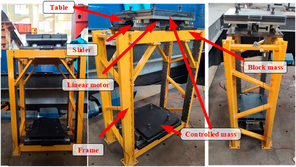
Figure 1. Configuration of the boundary-coordinating device (BCD).
The BCD can be used for RTHS, specifically in this study, for the shaking-table substructure test (STST), where the lower part of a structure is tested on the shaking table as the PS, while the rest is numerically simulated as the NS. The BCD serves to achieve boundary compatibility and equilibrium between the PS and NS. The RTHS using shaking tables includes a PC for solving the NS, the xPC, the dual-channel electromagnetic (DCE) controller for the BCD, the data acquisition (DAQ) system, the BCD, the specimen, the shaking table, and two host PCs, as shown in Figure 2.
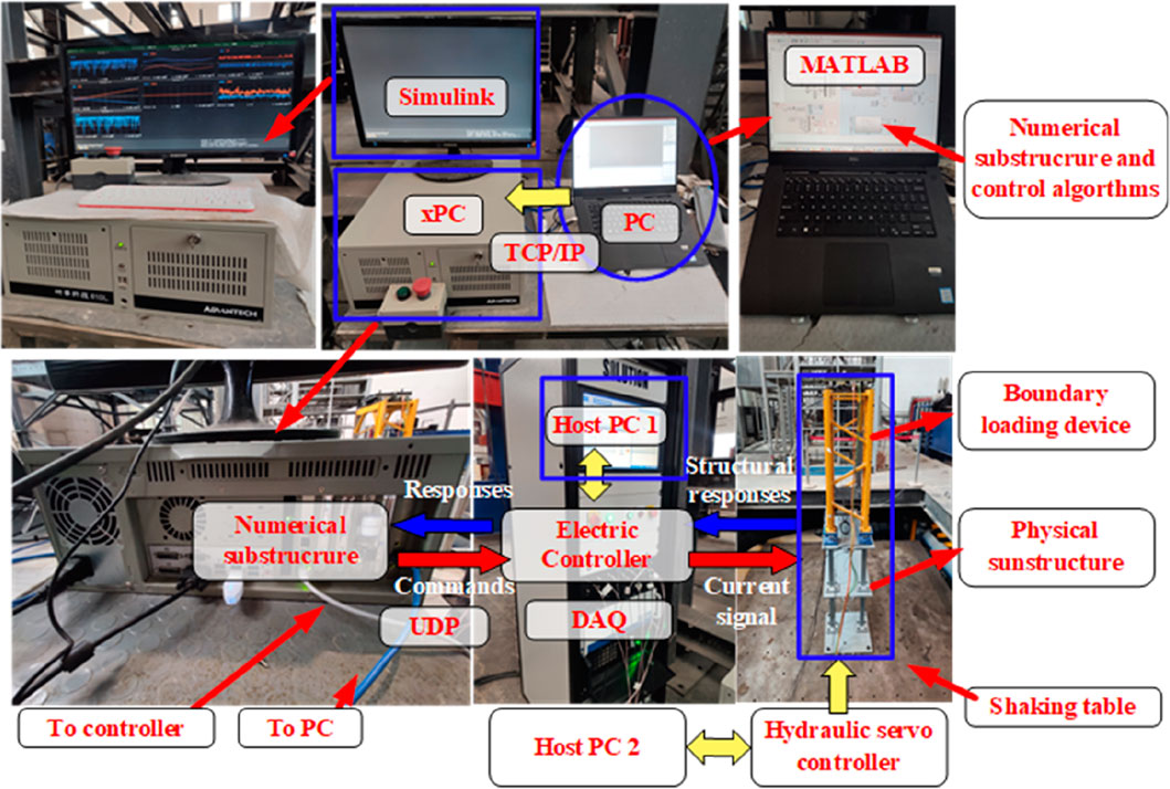
Figure 2. Configuration of real-time hybrid simulation (RTHS) using the BCD.
The PC for the NS first runs MATLAB/Simulink software to build a Simulink model including the NS and comprehensive control strategy for the RTHS. The model is then compiled and distributed to the xPC. The xPC is a high-performance PC, on which the xPC target environment is employed to calculate the control signal for the DCE controller by a 10-Gigabit network card through the UDP. The Ethernet cable is employed to set up a real-time communication between the xPC and the DCE controller at a frequency of 1 kHz, which results in a time delay of approximately 4 ms. The DCE controller is the host PC to control the BCD, which is integrated with several current amplifiers to drive two shakers by using a digital proportional–integral–differential (PID) control scheme. A signal conditioner modularizes the command signals and filters and the measured signals. The DAQ system is integrated in the DCE controller to synchronously collect the response data of equipment and structures. The host PC1 runs the graphical user interface for the DCE controller, which is used to configure the control scheme and store data from the DAQ system and the xPC. The DCE controller is set to run at a frequency of 2 kHz. Each shaker is driven by a linear motor actuator attached with a displacement sensor and an accelerometer. The measured signals are fed back to the DCE controller and further to the xPC for solving the next-step responses. The system is essentially a displacement-based control system.
Another host PC2 runs the graphical user interface for the hydraulic servo controller to control the shaking table to simulate the ground motion as the input to the structure. It employs an offline iteration scheme to improve its acceleration reproduction accuracy. The offline iteration would be completed before the RTHS and is not a part of the real-time loop.
The DCE controller used in this study cannot install high-performance hardware, such as SCRAMNet cards, for real-time data exchange. Instead, a general real-time communication scheme based on the UDP is proposed to solve this problem, as shown in Figure 3. In this scheme, the xPC is equipped with at least two network ports, one used to download the NS model and RTHS control scheme from the PC for compiling the NS model, while the other connects to the DCE controller for high-speed command and response-signal transmission through the UDP. In the RTHS system, the operating frequency of the target xPC is set to 1 kHz due to the computer limitation, while the operating frequency of the DCE controller is fixed at 2 kHz. The UDP is a broadcast protocol that solves the incompatible sampling rates to avoid signal blocking in the RTHS.
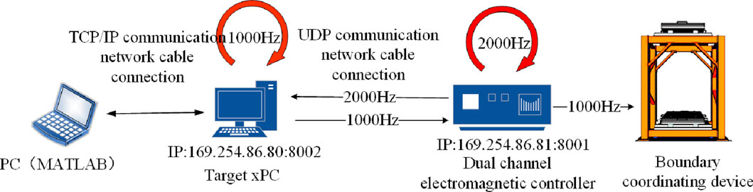
Figure 3. Real-time communication framework for substructures.
The proposed communication scheme primarily consists of a UDP configuration module, UDP-receiving module, and UDP-sending module, as shown in Figure 4. In the UDP configuration module, the getPCIInfo (tg,“installed”) command is executed to obtain the PCI bus and slot number of the target xPC for configuring the UDP receiving and sending modules, as shown in Figure 4A. Then, the UDP-receiving module is built with the IP address and the port of the target xPC, as shown in Figure 4B. It receives the feedback signal from the DCE controller and unpacks the data through the byte unpack procedure. If the signal timing is correct, the desired signal is obtained. Otherwise, it will wait until the correct signal is collected. In this module, a “For” iteration is used to improve the efficiency of receiving signal processing to achieve the signal rate compatibility. The iteration would be triggered five times for each step of the analysis. A sequence number is included in the data flow. Only when the sequence number of the message received by the UDP-receiving module is larger than the sequence number of the previous message is the received signal value deemed effective and then updated to ensure the normal signal timing. The process of the UDP signal-sending module is the opposite of that of the UDP signal-receiving module, as shown in Figure 4C, which sends the target commands to the DCE controller.
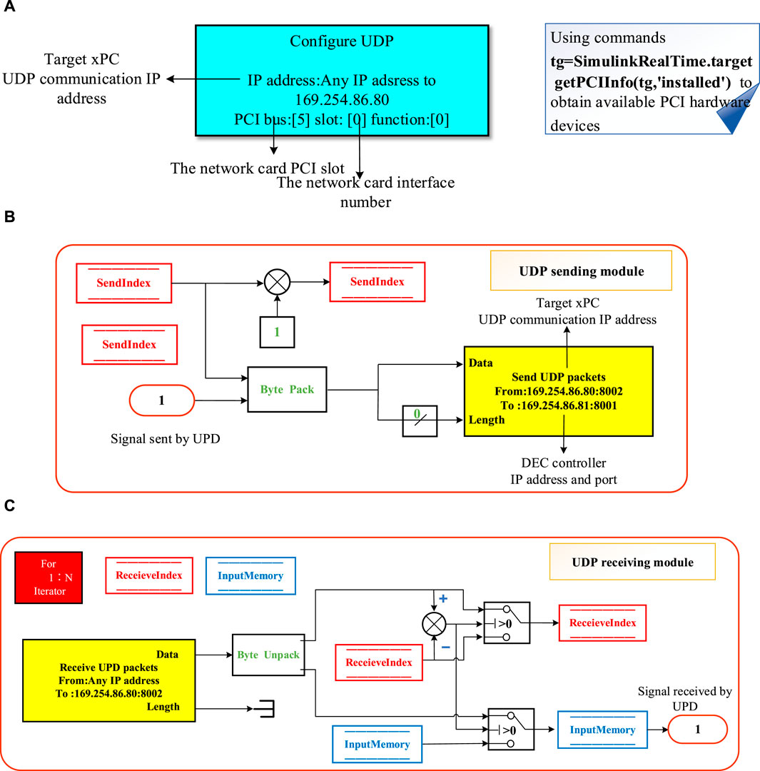
Figure 4. Real-time communication strategy. (A) UDP communication configuration. (B) UDP-receiving module. (C) UDP-sending module.
The simplified dynamic model, as shown in Figure 5, was developed to formulate the dynamic characteristics of the BCD, which will be used to develop the force command to the displacement command for the shakers. The two controlled masses driven by two shakers are represented as
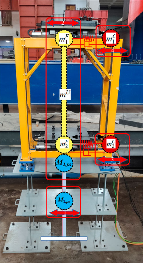
Figure 5. Simplified dynamic model.
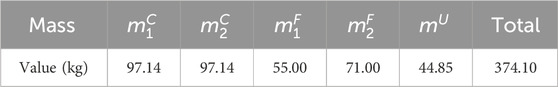
Table 1. Mass distribution of the simplified model.
With the command signal, the electromagnetic motor can drive the attached mass blocks. Furthermore, the reaction force required to balance the inertial force can be determined by the dynamics of the shakers formulated in the state space form, as shown in Eq. 1:
where,
It should be noted that if there exists rotation at the boundary interface where the BCD is attached, the rigid-body motion introduced by the rotation is to be considered in the dynamic formation of shakers.
The whole experimental system includes two control sub-systems, namely, the shaking table sub-system and BCD sub-system, as shown in Figure 6. The shaking table sub-system is a six-DOF shaking table that is employed to input seismic excitations. Its controller uses an offline iteration control method to improve the reproduction accuracy of acceleration. The shaking table has a size of 3.5 m × 3.5 m and a payload of 5 tons, which is sufficient for the experimental substructure with a mass of less than 0.5 ton. As a result, the mutual interaction between the shaking table sub-system and BCD sub-system is not obvious so that two sub-systems are independently considered.
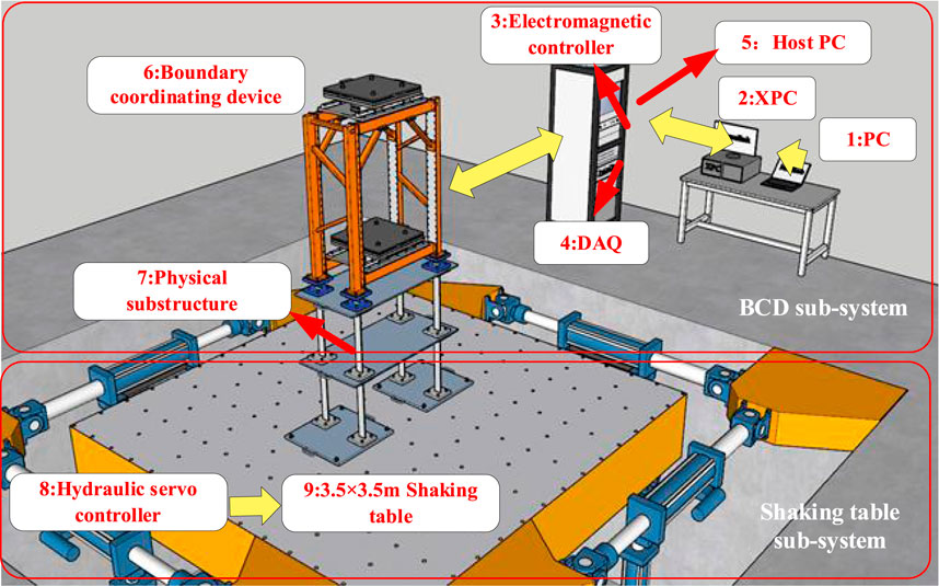
Figure 6. Hardware in the experimental system.
The electromagnetic shaker used in this study has no satisfactory working frequency beyond 20 Hz because it drives a large mass block. To improve its dynamic performance, Enhanced Three Variable Control (ETVC) has been developed (Tian et al., 2022b). ETVC is a modified version of the state variable control enhanced with additional predictive variables introduced to overcome the adverse effect of time delay. Details can be found elsewhere.
Each shaker in the BCD is equipped with an independent ETVC controller, whose feedback generator synthesizes feedback signals based on the relative displacement, absolute acceleration, and boundary acceleration of the physical substructure, as shown in Figure 7. Although each shaker uses the same type of linear motor, the parameters of the ETVC controller are different due to the installation location on the BCD. An interaction exists between the two exciters through the combination structure of the physical substructure and BCD (PS-BCD combination), which makes it difficult and complex to obtain the optimum parameters considering the coupling effect by theoretical analysis. The parameters of two ETVC controllers were determined by reproducing two uncorrelated white noises to have a good frequency response.
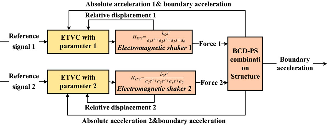
Figure 7. Performance improvement strategy for coupled loading devices.
The control scheme for the BCD sub-system is shown in Figure 8. The boundary acceleration response is measured and sent to the NS to calculate the reaction force and bending moment as the commands to the PS. The force commands are then converted to the relative accelerations and then integrated to the relative displacements as the reference commands for shakers. However, an electromagnetic shaking table with a basic PID control is incompetent due to its slow dynamic responses and large time delay. Therefore, the proposed ETVC and ATS compensator (Chae et al., 2013) are employed to make up for those weaknesses. In addition, a band-stop filter is introduced to decrease the influence introduced by the dynamics of PS-BCD combination, and a linear interpolation compensator is used to compensate the time lag of the band-stop filter.
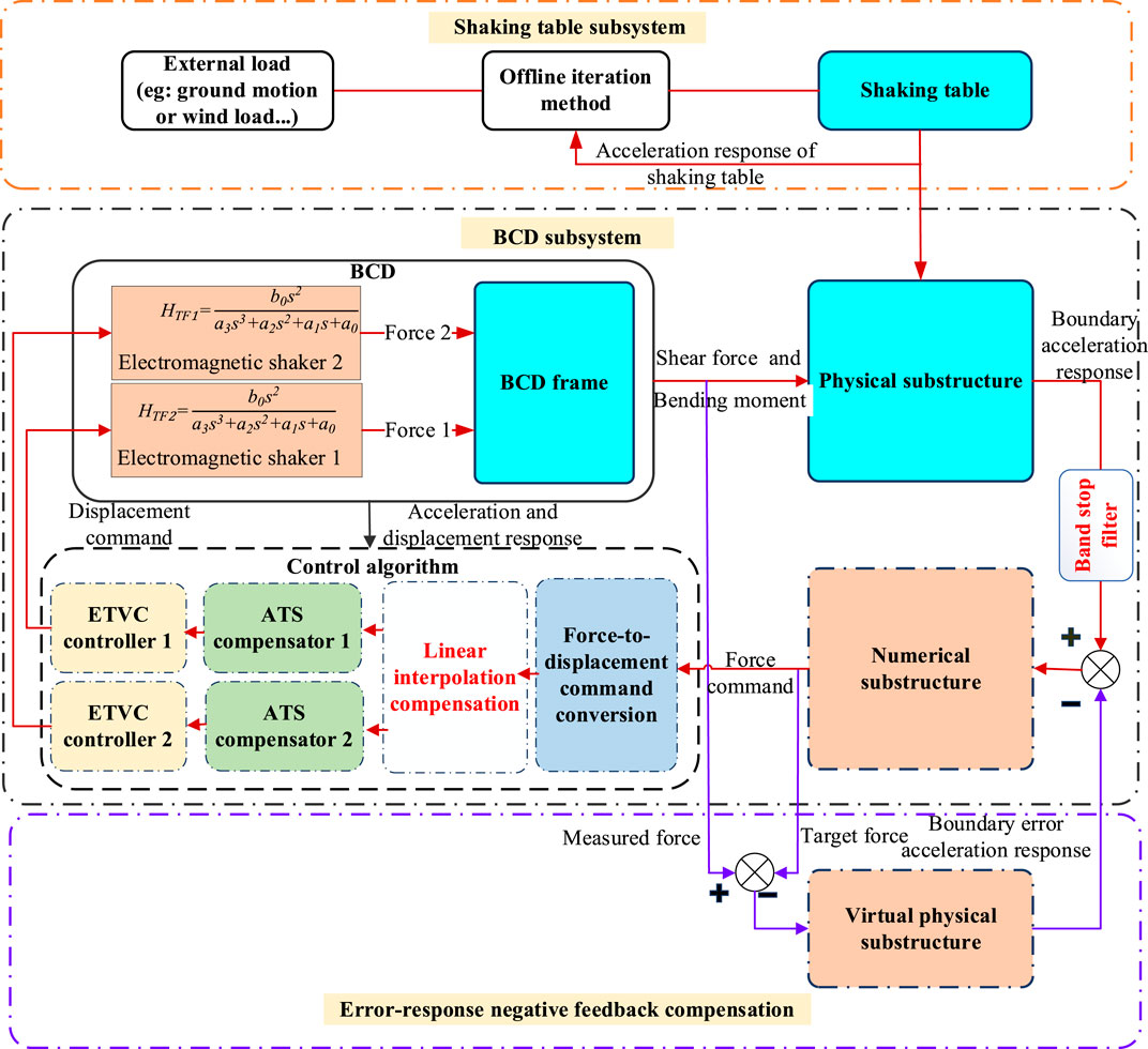
Figure 8. Block diagram of RTHS using error-response negative-feedback compensation.
In this study, the PS is excited by the shaking table from the bottom with a ground motion. The measured responses are fed back to the NS as the input at the interface between the PS and NS for the time history analysis. The reaction force obtained from the NS is then sent to the BCD mounted on the top of the PS. The reliable realization of the boundary force loading is the key to achieve the accurate reproduction of seismic responses of the entire structure. However, the dynamic characteristics and control–structure interactions of the loading devices make it difficult to perfectly impose those forces on the PS. Furthermore, the error will be accumulated continually and rapidly during the RTHS loop, which would cause the entire system to lose stability, particularly for light-damping structures. To this end, a compensation method is developed by using the error-introduced response to negatively correct the input to the NS. In this way, the boundary is maintained in perfect equilibrium and compatibility. Details can be found in the paper by Tian et al. (2022b).
As for the shaking table sub-system, an offline iteration method is implemented to improve the acceleration reproduction of ground motion, which consists of two stages: system identification and iterative process (Tian et al., 2021). The transfer function matrix of the shaking table is identified by white noise, and its inverse is then calculated. The target signal and the response are compared, and the difference is translated into an increment in the drive signal. The new drive signal is then updated to drive the shaking table. This iteration will proceed until the termination criterion was triggered.
The two bottom stories of a four-story shear-type steel frame are selected as the PS, as shown in Figure 9. Each floor is modeled by a 14-mm-thick steel plate with a size of 1,200 ×600 mm. The mass is approximately 84 kg. Each plate is supported by four steel columns. The height of each column is 540 mm, and the cross section is rectangular with a size of 60 ×8 mm. The weak direction of the columns is along the loading direction.
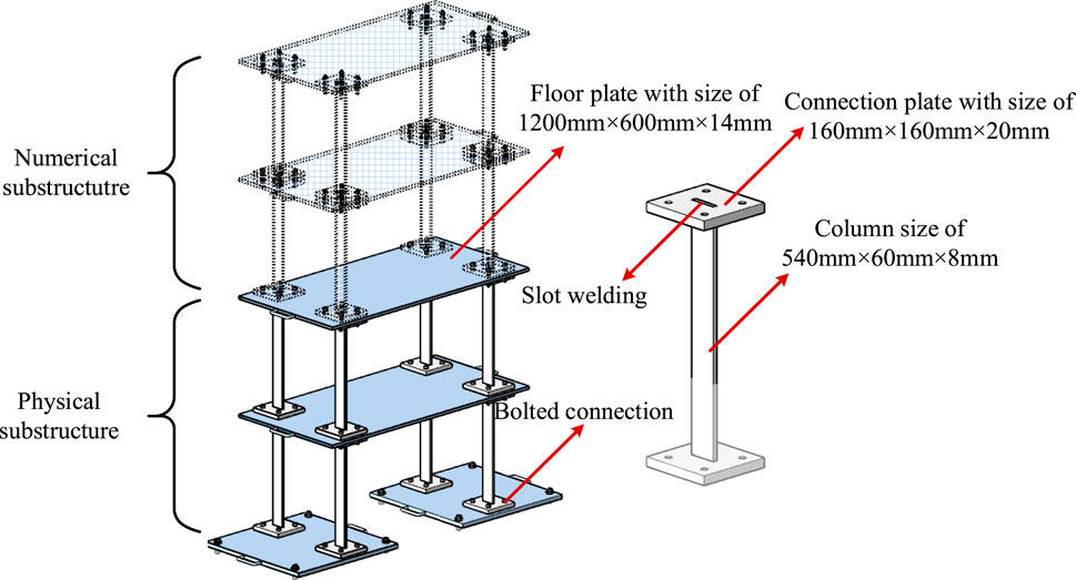
Figure 9. Design of the physical substructure.
A free-vibration test was conducted as the pre-test to obtain the dynamic characteristics of the PS. Each story of the specimen was attached with one displacement transducer and one uniaxial accelerometer for measuring displacement and acceleration responses, respectively, as shown in Figure 10. In the RTHS, the displacement transducers were removed. Four three-directional load cells were installed on top of the specimen and connected to the BCD to measure the boundary force and moment. The boundary shear force is the sum of the measured shear force, while the bending moment is estimated by multiplying the axial forces on both sides of their arms. Another two uniaxial accelerometers were attached to two controlled masses for ETVC. One uniaxial accelerometer was attached to the shaking table for measuring the ground motion. The relative displacements of the controlled masses to BCD are measured using optical grating rulers.
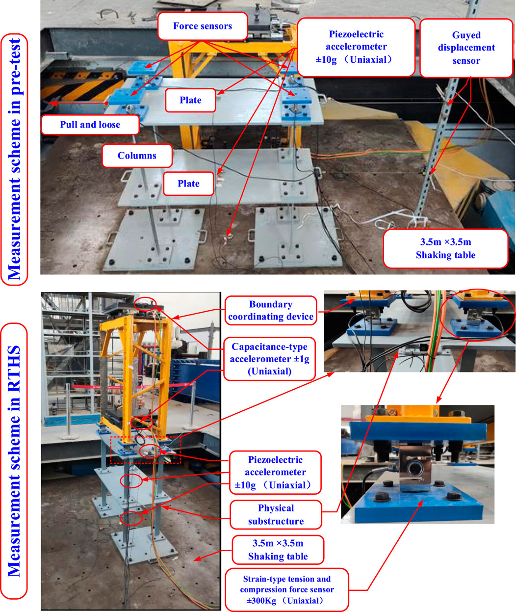
Figure 10. Measurement scheme of the specimen.
Frequency analysis based on the free-vibration test yielded the first and second frequencies as 4.952 Hz and 13.997 Hz, respectively, as shown in Figure 11. From the amplitude decay of the displacement response, the damping ratio corresponding to the first vibration mode was approximately 0.143%, which was adopted for all vibration modes hereafter. These identified values were used to calibrate the virtual PS model for the error compensator. The mass, stiffness, and damping matrices are given as follows:
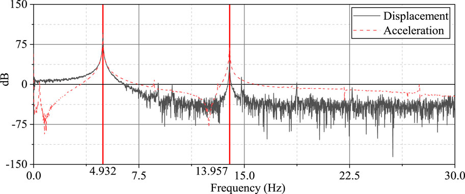
Figure 11. Frequency analysis based on the free-vibration test.
The NS is the top two stories of the four-story steel frame. The structural information is given as follows. These values are intentionally designed according to the vibration frequencies, which are located within the working frequency range of the BCD, as follows:
The whole structure is obtained by assembling the PS and NS. The natural frequencies of the entire structural model and each substructure are given in Table 2.
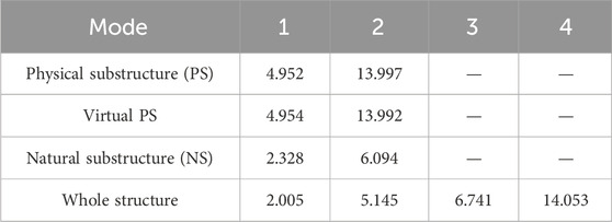
Table 2. Natural frequencies (unit: Hz).
Three ground acceleration records are used for RTHS, namely, the N-S component of the ground motion recorded at El Centro in 1940, the fault–normal component of the motion recorded during Chi-Chi earthquake in 1999, and the N-S component of the motion recorded at the Wolong station in the 2008 Wenchuan earthquake. The time history of each motion is shown in Figure 12, together with their acceleration response spectra. The amplitude of each motion is scaled to 0.1 g.
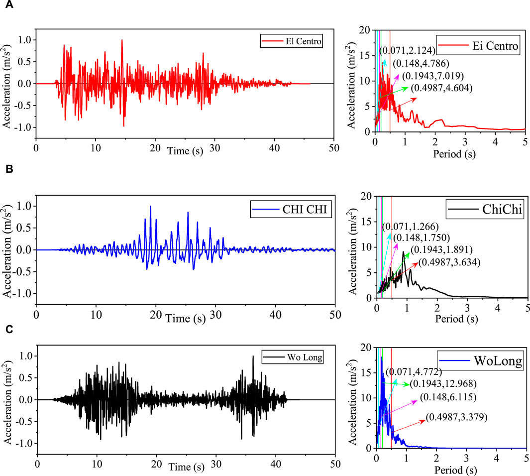
Figure 12. Ground motions used for RTHS (peak ground acceleration [PGA] scaled to 0.1 g). (A) El Centro ground motion. (B) Chi-Chi ground motion. (C) Wolong ground motion.
Three indicators are used to quantitatively evaluate the RTHS performance in the time domain, namely, time delay, tracking error, and peak tracking error, as defined by Condori Uribe et al. (2023). Estimation of time delay in the controlled response is based on the quantification of the similarity between the target and measured signals by calculating the cross-correlation coefficient. The tracking error is obtained by the normalized root mean square (NRMS) of the error between the target command and measured response signals. The peak tracking error is calculated as the maximum relative error between the target command and measured response signals.
Each indicator is calculated for the shaker responses, the boundary forces and boundary acceleration responses to assess the tracking control performance, the boundary loading performance, and the overall global RTHS performance, respectively, as summarized in Table 3.
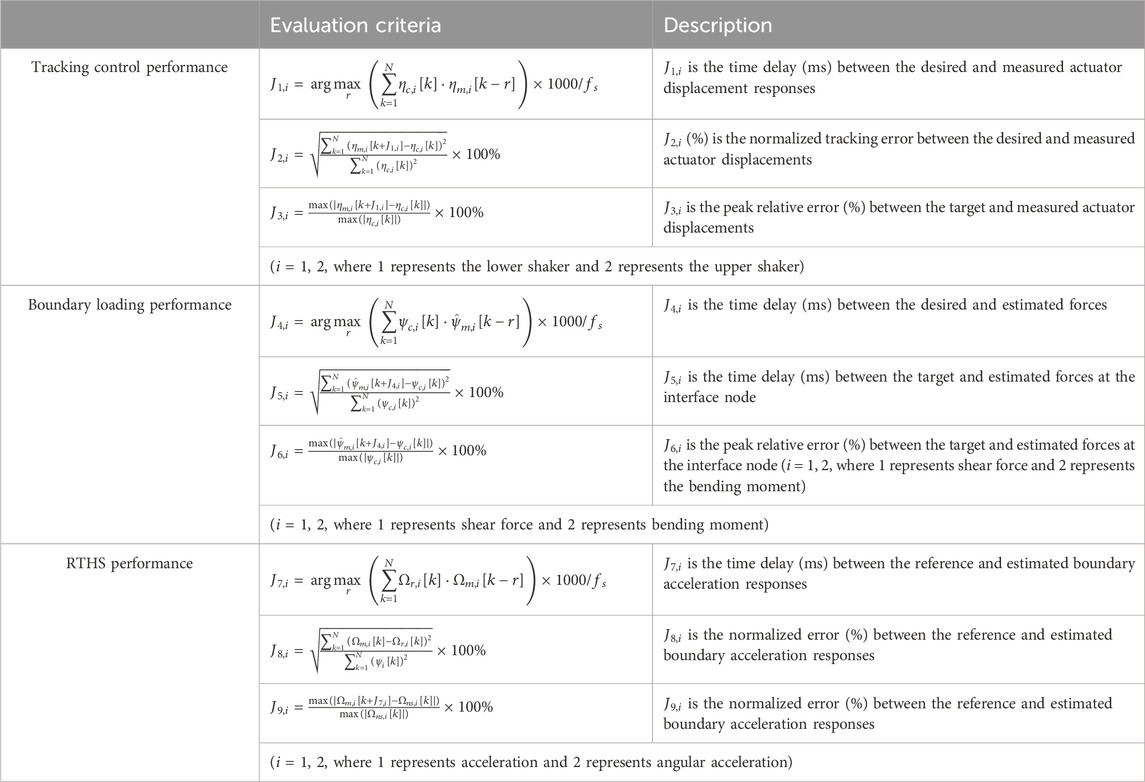
Table 3. Assessment of control performance in the ma-RTHS benchmark problem.
The dynamics of two unidirectional shakers used in the BCD are improved by using an ETVC control scheme and ATS compensator. To verify the effectiveness of the proposed method, a white noise signal with a frequency range of 0.01–20 Hz was generated to identify the performance of two shakers with the PID controller, ETVC controller, and ETVC controller with the ATS compensator. The time domain and frequency domain responses are shown in Figures 16A–C for the three control methods, respectively. The first three criteria were calculated to evaluate the tracking control performance of the controller, as summarized in part I of Table 4.
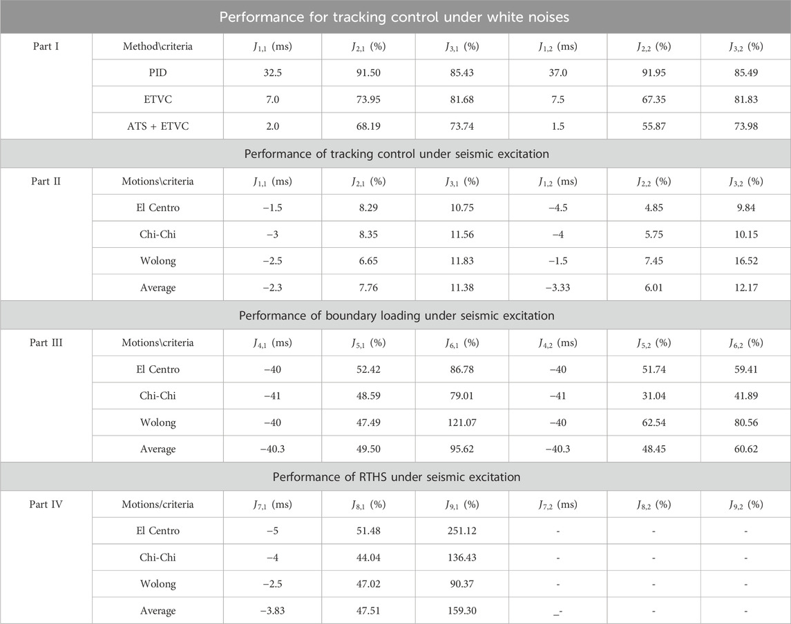
Table 4. Control performance in the ma-RTHS benchmark.
The performance of the two shakers with the PID controller is poor, with a delay larger than 30 ms and an RMSE larger than 90%. The RMSE rapidly increases with frequency because the PID-controlled shakers exhibited significant attenuation when the loading frequency was larger than 2.5 Hz, which does not meet the requirements of RTHS. As a result, ETVC was introduced to the outer loop of each shaker to improve its performance. The parameters of two ETVC controllers were adjusted for a good frequency response, and the final resulting gains of the three generators in ETVC are given in Table A in Supplementary Material. Figures 13A–C shows that ETVC can effectively improve the displacement reproduction in a frequency range of 0.05–20 Hz, and its RMSE in the frequency domain was significantly improved compared with the PID controller, from nearly 200% to 50%. In the time domain, the delay was also effectively reduced from more than 30 ms to approximately 7 ms. Furthermore, the RMSEs under the ETVC were 73.95% and 67.35% for the lower and upper shakers, respectively (PID controller, 91.50% and 91.95%, respectively). However, the ETVC algorithm has limited improvement on the peak tracking error criterion, J3, which was only reduced by about 4%, because the lower shaker has an over-adjusted gain within 5–7.5 Hz to obtain a larger frequency range, while the upper shaker has an obvious attenuation of approximately 12.5 Hz due to the interaction with the steel frame.
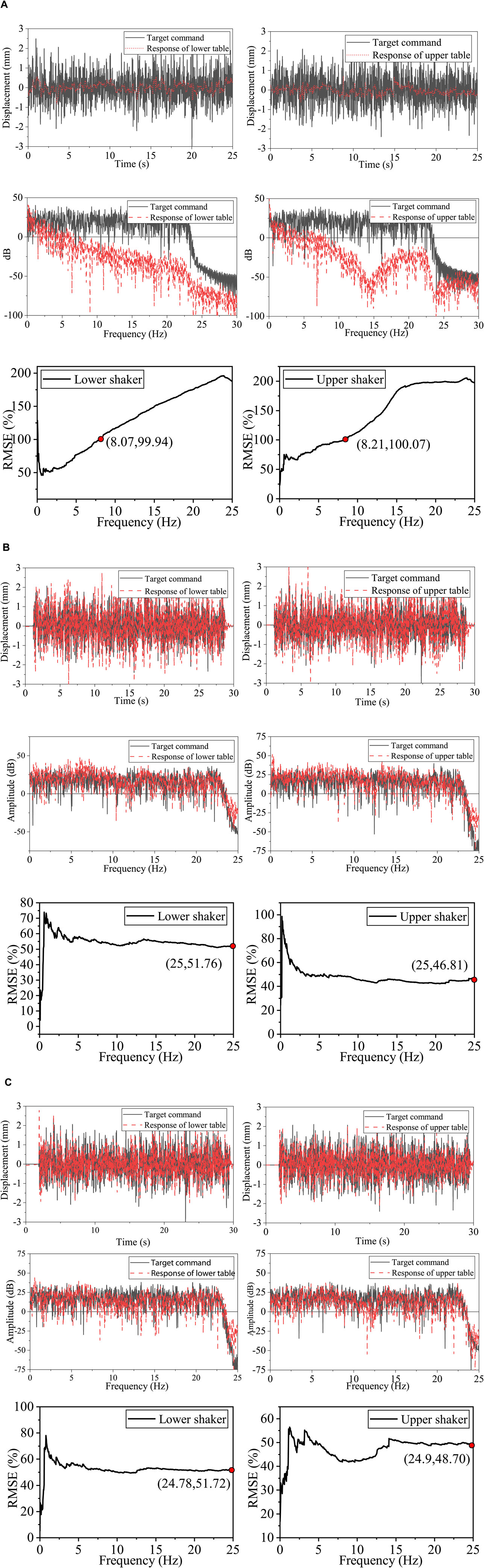
Figure 13. Experimental validation for enhanced three-variable control (ETVC) and adaptive time series (ATS) by white noises. (A) Control performance of the two shakers with a proportional–integral–differential (PID) controller. (B) Control performance of the two shakers with an ETVC controller. (C) Control performance of the two shakers with the ETVC with an ATS controller.
To reduce time delay, ATS was combined with ETVC. A better performance can be observed. The time delays were reduced to 2 ms. However, the RMSEs were not changed significantly.
A total of three rounds of RTHS were successively conducted to investigate tracking control performance using three different ground motions with the same peak ground acceleration (PGA) of 0.1 g. The tracking control performance under the El Centro ground motion is shown in Figure 14, while the corresponding results of Chi-Chi ground motion and Wolong ground motion are presented Figures A, B in Supplementary Material, respectively. Good tracking performances were observed on both lower and upper shakers with averaged RMSEs of 7.76% and 6.01%, respectively, as given in part II of Table 4. The time delay was completely compensated and even overcompensated by approximately 2–3 ms. It was noted that the proposed UDP communication strategy can realize packet loss-free communication, but there is a closed-loop delay of 3 ms between the controller and the xPC target. The lead delay was caused by the UDP communication strategy, which causes the feedback signal of the ATS compensator to be delayed by 2–3 ms in the RTHS loop, resulting in an overcompensated event. However, the lead delay will help offset some of the delay of the band-stop filter being used, so it is not to be compensated.
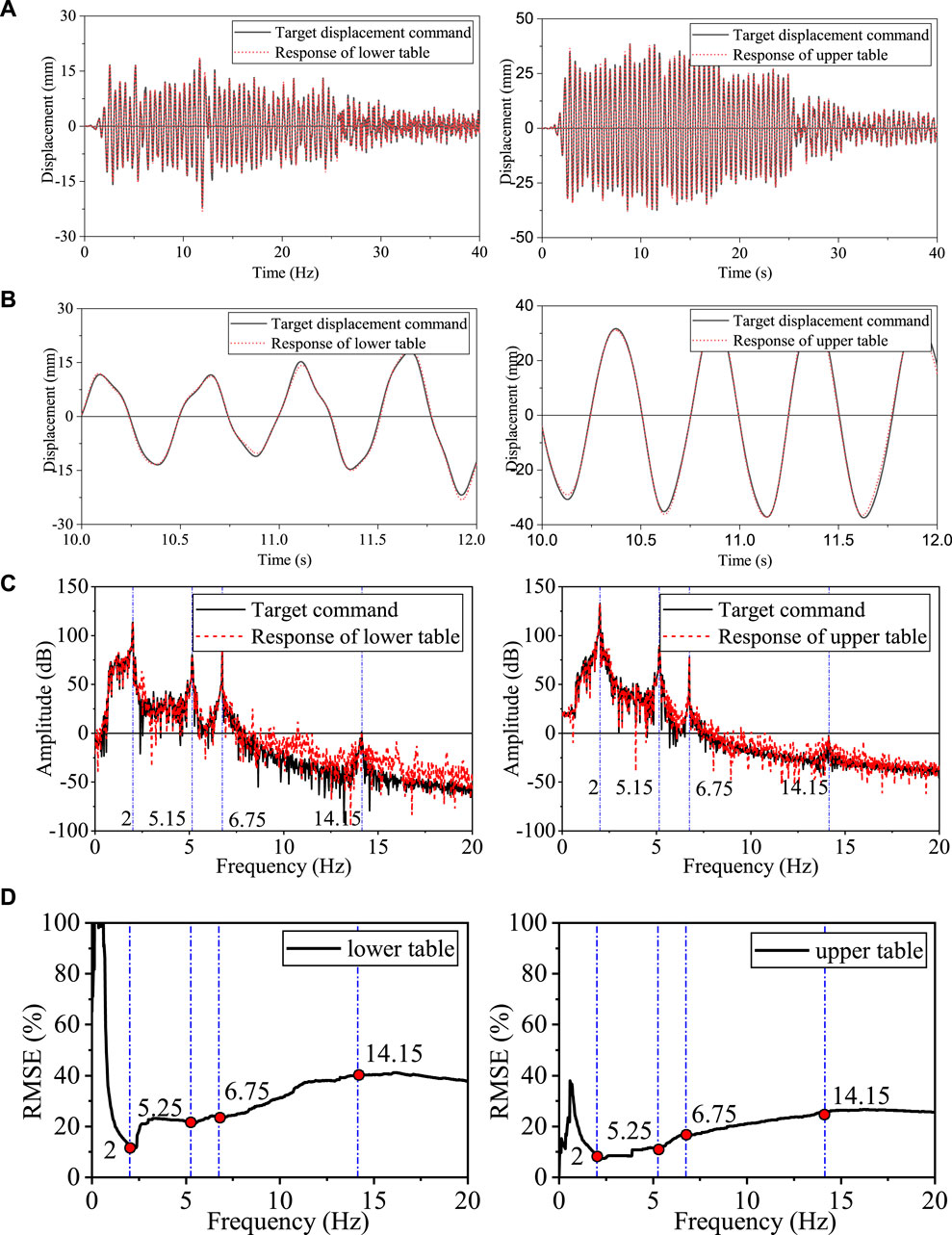
Figure 14. Response of the two shakers in RTHS under El Centro ground motion. (A) Relative displacement responses of the two shakers in RTHS. (B) Close view of relative displacement responses. (C) Frequency analysis of relative displacement responses. (D) Relative displacement responses of the two shakers in RTHS in the frequency domain.
The two shakers had similar tracking performance, as shown in part II of Table 4. The upper shaker performed slightly better than the lower shaker in terms of history tracking, i.e., J2, but slightly worse in tracking the peak response, i.e., J3. Further analysis for both displacements in the frequency domain is given in Figure 14. It can be observed again that both shakers well-tracked the responses throughout the first four natural frequencies. As the frequency range increases, the RMSE in the frequency domain changed slowly at a low value. It proved that ETVC can effectively improve the high-frequency reproduction performance of the two shakers. It should be noted that the displacement command was converted from the force command. A low-pass filter was used to avoid a large shifting in the displacement command, which resulted in a larger RMSE in the extremely low-frequency domain.
RTHTs in this study implemented dynamic forces as the boundary conditions between the NS and PS. Therefore, the evaluation criteria for boundary loading performance, i.e.,
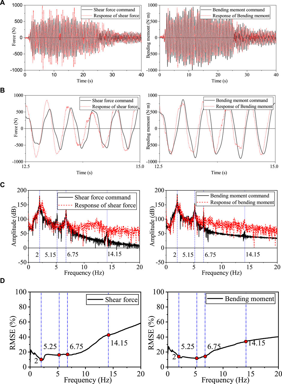
Figure 15. Force implementation of the BCD in RTHS under El Centro ground motion. (A) Boundary force responses of the BCD in the time domain. (B) Close view of boundary force responses. (C) Boundary force responses in RTHS in the frequency domain. (D) RMSE of the boundary force response in the frequency domain.
Further analysis in the frequency domain is shown in Figure 15C. It can be observed that good force tracking has been achieved throughout the first three natural frequencies. The major difference between the command and response was concentrated in the high-frequency range larger than 6.75 Hz, where the force response contains more high-frequency components than the force command. The high-frequency components might be generated by slight time-varying phase differences between the two shakers, which makes it difficult for the two shakers to be accurately controlled in the high-frequency domain. The numerical simulation for RTHS using the BCD verified this reason (Tian et al., 2022a; Tian et al., 2022b). In addition, the force implementation was inevitably affected by the dynamic nature of the PS-BCD combination. It is worth noting that the first two frequencies of the PS-BCD combination are 2.875 Hz and 12.725 Hz. At the two frequencies, the force implementation became worse, and the corresponding RMSE curve in the frequency domain increased rapidly, as shown in Figure 15D.
Corresponding to the boundary force conditions, the boundary acceleration is fed back to the numerical substructure to form an RTHS closed loop. As a result, the boundary acceleration in RTHS is chosen to evaluate the performance of RTHS by comparing with the overall simulation for RTHS. In practice, a virtual PS is analyzed simultaneously with the NS on the xPC target to obtain boundary acceleration. The boundary acceleration calculated by this virtual RTHS is sent to the DCE controller for recording and comparing with the measured boundary acceleration. The evaluation criteria for RTHS performance, i.e.,
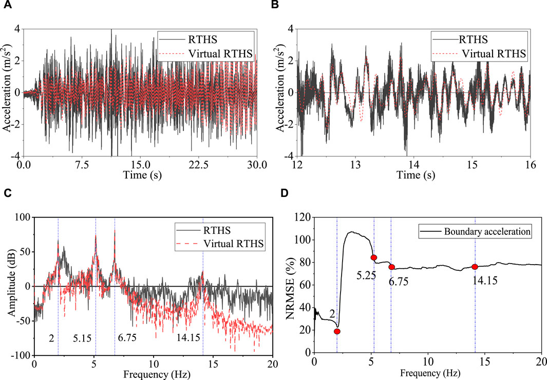
Figure 16. Comparison of boundary acceleration responses between RTHS and virtual RTHS under El Centro ground motion. (A) Time history response. (B) Close view. (C) Frequency response. (D) RMSE in the frequency domain.
This study evaluated a multi-dimensional boundary loading strategy by implementing RTHS using the BCD, which can simultaneously apply shear forces and bending moments at the PS boundary through a parallel configuration of dual shaking tables. A comprehensive control scheme was proposed to solve the control difficulties introduced by the communication strategy, loading capacity, and interaction of multiple loading devices. Three performance indicators were employed to quantify the quality of the RTHS. Although the performance of the shakers was limited, the boundary forces were consistently reproduced. Some conclusions are drawn as follows.
(1) The BCD consists of two electromagnetic shakers in parallel configuration to realize a shear–moment boundary condition. This configuration could be easily constructed in a modern engineering laboratory. By transforming the boundary forces into displacement control signals, the force implementation in RTHS was successfully realized with an acceptable accuracy.
(2) The ETVC strategy is based on the state variable control but enhanced with additional absolute acceleration feedback and predictive variables. It is able to advance the dynamic response of the loading system and overcome the adverse effect of time delay. The test results show that the top working frequency of both shakers was increased from 2.5 Hz to 20 Hz, and the time delay was reduced from 30 ms to 7 ms.
(3) Although both the upper and lower shakers have good tracking performance, with an average RMSE of 7.76% and 6.01%, respectively, the corresponding boundary loading performance is not so good with an RMSE of shear force and bending moment of 49.50% and 48.45%, respectively. A major reason is the coupling effects between the shakers in ma-RTHS. Therefore, improving the tracking performance of individual shakers may not necessarily result in an overall enhancement of ma-RTHS performance. It is necessary to develop advanced force implementation technologies with higher precision and better robustness for ma-RTHS.
The original contributions presented in the study are included in the article/Supplementary Material; further inquiries can be directed to the corresponding author.
YT: writing–original draft, project administration, methodology, funding acquisition, and conceptualization. QL: writing–review and editing, validation, supervision, and methodology. CB: writing–review and editing, methodology, investigation, and formal analysis. FF: writing–review and editing, visualization, validation, methodology, investigation, formal analysis, and data curation. TW: writing–review and editing, supervision, project administration, and funding acquisition.
The author(s) declare that no financial support was received for the research, authorship, and/or publication of this article. The research was financially funded by the China Postdoctoral Science Foundation (2023M742001), the Scientific Research Fund of the Institute of Engineering Mechanics, the China Earthquake Administration (2023D05), and the National Science Fund for Distinguished Young Scholars (52125806). The opinions, findings, conclusions, or recommendations expressed in this paper are solely those of the authors and do not necessarily reflect the views of the sponsors.
The authors declare that the research was conducted in the absence of any commercial or financial relationships that could be construed as a potential conflict of interest.
All claims expressed in this article are solely those of the authors and do not necessarily represent those of their affiliated organizations, or those of the publisher, the editors, and the reviewers. Any product that may be evaluated in this article, or claim that may be made by its manufacturer, is not guaranteed or endorsed by the publisher.
The Supplementary Material for this article can be found online at: https://www.frontiersin.org/articles/10.3389/fbuil.2024.1424108/full#supplementary-material
Ahmadizadeh, M., Mosqueda, G., and Reinhorn, A. M. (2008). Compensation of actuator delay and dynamics for real-time hybrid structural simulation. Earthq. Eng. Struct. Dyn. 37 (1), 21–42. doi:10.1002/eqe.743
Chae, Y., Kazemibidokhti, K., and Ricles, J. M. (2013). Adaptive time series compensator for delay compensation of servo-hydraulic actuator systems for real-time hybrid simulation. Earthq. Eng. Struct. Dyn. 42 (11), 1697–1715. doi:10.1002/eqe.2294
Chae, Y., Lee, J., Park, M., and Kim, C. (2018). Real-time hybrid simulation for an RC bridge pier subjected to both horizontal and vertical ground motions. Earthq. Eng. Struct. Dyn. 47 (7), 1673–1679. doi:10.1002/eqe.3042
Chae, Y., Rabiee, R., Dursun, A., and Kim, C. Y. (2017). Real-time force control for servo-hydraulic actuator systems using adaptive time series compensator and compliance springs. Earthq. Eng. Struct. Dyn. 47 (4), 854–871. doi:10.1002/eqe.2994
Chen, C., and Ricles, J. M. (2010a). Improving the inverse compensation method for real-time hybrid simulation through a dual compensation scheme. Earthq. Eng. Struct. Dyn. 38 (10), 1237–1255. doi:10.1002/eqe.904
Chen, C., and Ricles, J. M. (2010b). Tracking error-based servo hydraulic actuator adaptive compensation for real-time hybrid simulation. J. Struct. Eng. ASCE 136 (4), 432–440. doi:10.1061/(ASCE)ST.1943-541X.0000124
Condori Uribe, J., Salmeron, M., Patino, E., Montoya, H., Dyke, S. J., Silva, C., et al. (2023). Experimental benchmark control problem for multi-axial real-time hybrid simulation. Front. Built Environ. 9, 1270996. doi:10.3389/fbuil.2023.1270996
Conrad, F., and Jensen, C. J. D. (1987). Design of hydraulic force control systems with state estimate feedback. IFAC Proc. Vol. 20, 307–312. doi:10.1016/s1474-6670(17)55388-4
Darby, A. P., Williams, M. S., and Blakeborough, A. (2002). Stability and delay compensation for real-time substructure testing. J. Eng. Mech. ASCE 128 (12), 1276–1284. doi:10.1061/(ASCE)0733-9399(2002)128:12(1276)
Dimig, J., Shield, C., French, C., Bailey, F., and Clark, A. (1999). Effective force testing: a method of seismic simulation for structural testing. J. Struct. Eng. ASCE 125 (9), 1028–1037. doi:10.1061/(ASCE)0733-9445(1999)125:9(1028)
Friedman, A., Dyke, S. J., Phillips, B., Ahn, R., Dong, B., Chae, Y., et al. (2015). Large-scale real-time hybrid simulation for evaluation of advanced damping system performance. J. Struct. Eng. 141 (6), 04014150. doi:10.1061/(asce)st.1943-541x.0001093
Gao, X., Castaneda, N., and Dyke, S. J. (2014). Experimental validation of a generalized procedure for MDOF real-time hybrid simulation. J. Eng. Mech. 140 (4), 04013006. doi:10.1061/(asce)em.1943-7889.0000696
Horiuchi, T., Inoue, M., Konno, T., and Namita, Y. (1999). Real-time hybrid experimental system with actuator delay compensation and its application to a piping system with energy absorber. Earthq. Eng. Struct. Dyn. 28 (10), 1121–1141. doi:10.1002/(SICI)1096-9845(199910)28:10<1121::AID-EQE858>3.0
Nachtigal, C. L., and Martin, M. D. (1990). Instrumentation and control: fundamentals and applications. Hoboken, NJ: John Wiley and Sons, Inc.
Najafi, A., Fermandois, G. A., Dyke, S. J., and Spencer, B. F. (2023). Hybrid simulation with multiple actuators: a state-of-the-art review. Eng. Struct. 276, 115284. doi:10.1016/j.engstruct.2022.115284
Nakata, N., Spencer, B. F., and Elnashai, A. S. (2010). Sensitivity-based external calibration of multiaxial loading system. J. Eng. Mech. 136 (2), 189–198. doi:10.1061/(asce)0733-9399(2010)136:2(189)
Nakata, N., Spencer, B. F., and Elnashai, A. S. (2007). Multi-dimensional mixed-mode hybrid simulation control and applications. Newmark Structural Engineering Laboratory Report Series 005. Available at: http://hdl.handle.net/2142/3628.
Nakata, N., and Stehman, M. (2012). Substructure shake table test method using a controlled mass: formulation and numerical simulation. Earthq. Eng. Struct. Dyn. 41, 1977–1988. doi:10.1002/eqe.2169
Ou, G., Ozdagli, A. I., Dyke, S. J., and Wu, B. (2015). Robust integrated actuator control: experimental verification and real-time hybrid-simulation implementation. Earthq. Eng. Struct. Dyn. 44 (3), 441–460. doi:10.1002/eqe.2479
Palacio-Betancur, A., and Gutierrez Soto, M. (2019). Adaptive tracking control for real-time hybrid simulation of structures subjected to seismic loading. Mech. Syst. Signal Process. 134, 106345. doi:10.1016/j.ymssp.2019.106345
Palacio-Betancur, A., and Gutierrez Soto, M. (2023). Recent advances in computational methodologies for real-time hybrid simulation of engineering structures. Archives Comput. Methods Eng. 30 (3), 1637–1662. doi:10.1007/s11831-022-09848-y
Phillips, B. M., and Spencer, B. F. (2013). Model-based multiactuator control for real-time hybrid simulation. J. Eng. Mech. 139 (2), 219–228. doi:10.1061/(asce)em.1943-7889.0000493
Shield, C. K., French, C. W., and Timm, J. (2001). Development and implementation of the effective force testing method for seismic simulation of large–scale structures. Philosophical Trans. R. Soc. A Math. Phys. Eng. Sci. 359, 1911–1929. doi:10.1098/rsta.2001.0879
Sivaselvan, M., Reinhorn, A. M., Shao, X. Y., and Weinreber, S. (2008). Dynamic force control with hydraulic actuators using added compliance and displacement compensation. Earthq. Eng. Struct. Dyn. 37, 1785–1800. doi:10.1002/eqe.837
Stefanaki, A., and Sivaselvan, M. V. (2018). A simple strategy for dynamic substructuring: I. concept and development. Earthq. Eng. Struct. Dyn. 47 (9), 1801–1822. doi:10.1002/eqe.3039
Tian, Y., Shao, X., Zhou, H., and Wang, T. (2020). Advances in real-time hybrid testing technology for shaking table substructure testing. Front. Built Environ. 6, 123. doi:10.3389/fbuil.2020.00123
Tian, Y., Wang, T., Shi, Y., Han, Q., and Pan, P. (2021). Offline iterative control method using frequency-splitting to drive double-layer shaking tables. Mech. Syst. Signal. Process. 152, 107443.
Tian, Y., Wang, T., and Zhou, H. (2022b). Reproduction of seismic responses of wind turbine tower by hybrid tests considering shear and bending coupled boundary control. Adv. Struct. Eng. 25 (13), 2675–2690. doi:10.1177/13694332221104277
Tian, Y., Wang, T., Zhou, H., and Du, C. (2022a). Shaking-table substructure test using a MDOF boundary-coordinating device. Earthq. Eng. Struct. Dyn. 51 (15), 3658–3679. doi:10.1002/eqe.3741
Wallace, M. I., Wagg, D. J., and Neild, S. A. (2005). An adaptive polynomial based forward prediction algorithm for multi-actuator real-time dynamic substructuring. Proc. R. Soc. A Math. Phys. Eng. Sci. 461 (2064), 3807–3826. doi:10.1098/rspa.2005.1532
Xu, Y., Zhou, H., Shao, X., and Wang, T. (2019). Performance study of sliding mode controller with improved adaptive polynomial-based forward prediction. Mech. Syst. Signal Process. 133, 106263.
Keywords: shaking-table substructure test, force control, boundary coordinating, enhanced three-variable control method, error-response negative-feedback compensation method
Citation: Tian Y, Li Q, Bu C, Fan F and Wang T (2024) Evaluation of control accuracy for a boundary-coordinating device in a real-time hybrid test. Front. Built Environ. 10:1424108. doi: 10.3389/fbuil.2024.1424108
Received: 27 April 2024; Accepted: 03 June 2024;
Published: 08 July 2024.
Edited by:
Jia Guo, Kyoto University, JapanReviewed by:
Ge Yang, Wuhan University of Technology, ChinaCopyright © 2024 Tian, Li, Bu, Fan and Wang. This is an open-access article distributed under the terms of the Creative Commons Attribution License (CC BY). The use, distribution or reproduction in other forums is permitted, provided the original author(s) and the copyright owner(s) are credited and that the original publication in this journal is cited, in accordance with accepted academic practice. No use, distribution or reproduction is permitted which does not comply with these terms.
*Correspondence: Yingpeng Tian, eWluZ3Blbmd0aWFuQDE2My5jb20=
Disclaimer: All claims expressed in this article are solely those of the authors and do not necessarily represent those of their affiliated organizations, or those of the publisher, the editors and the reviewers. Any product that may be evaluated in this article or claim that may be made by its manufacturer is not guaranteed or endorsed by the publisher.
Research integrity at Frontiers
Learn more about the work of our research integrity team to safeguard the quality of each article we publish.