 Connell S. Miller
 Gregory A. Kopp
94% of researchers rate our articles as excellent or good
Learn more about the work of our research integrity team to safeguard the quality of each article we publish.
Find out more
ORIGINAL RESEARCH article
Front. Built Environ., 07 June 2024
Sec. Wind Engineering and Science
Volume 10 - 2024 | https://doi.org/10.3389/fbuil.2024.1398472
Air-permeable multilayer cladding (vinyl siding, roof pavers, discontinuous metal roofing, solar panels, etc.) are one of the most common types of building components in North America. Their defining aerodynamic feature is that they have an air cavity separating the component from the sheathing, studs, or interior layer. Due to air-permeability, external wind loads can transfer into the air cavity between the layers. Although these cladding systems have similar geometries in many ways, design loads are not generally available for such systems. This study aims to synthesize the available literature on the pressure equalization factor, which is the proportion of external load acting on the cladding and provide a framework for design wind loads on air-permeable multilayer cladding systems. To accomplish this, the many factors that affect the pressure equalization factor, such as the gap-to-cavity-depth ratio, panel size, and exposure are discussed. Then, the pressure equalization factors from multiple studies are combined to examine the effect of effective area on the pressure equalization factor. Finally, recommendations for implementing these guidelines into design standards are provided.
Cladding is a broad term used to describe the outer layer of a building that protects it from the elements. It is present on most buildings and comes in many variations. Air-permeable multilayer cladding is one of the most common types of building materials in North America. It includes such materials as vinyl siding, roof pavers, discontinuous metal roofing, and asphalt shingles. A feature of these cladding systems is that they have an air cavity separating the exterior cladding layer from the interior layer such as air barriers, sheathing, and other materials. The primary use of this air cavity is for installation purposes and drainage of rainwater. There is relatively little design guidance for determining the wind loads on air-permeable multilayer cladding systems. For example, ASCE 7-22 (2022), section C30.1.5 indicates that:
“[…] If the designer desires to determine the pressure differential across a specific cladding element in combination with other elements comprising a specific building envelope assembly, appropriate pressure measurements should be made on the applicable building envelope assembly or reference should be made to recognized literature […]”
In other words, this tells the designer that they need to search for the answer. Some design standards for specific building products provide some guidance for determining the net loads on air-permeable multilayer cladding. An example of this is ASTM D3679-21 (2021), which states in Annex 1 that the net loads on vinyl siding is equal to half of the design external pressure. Another example of this are solar panels in ASCE 7-22 (2022), which provides net loading for solar panels in Section 29.4.4 based on the effective wind area, the height of the solar panel from the roof, and whether the solar panel is on the edge of the array. Although both have similar aerodynamic mechanisms that drive the net loads on the system, the design standards are vastly different in how they calculate the net loads.
The lack of standardized design guidelines for these products is due to the complexity of the interaction of external wind loads with the flows in and through air-permeable multilayer cladding. Because of the air-permeability, external wind loads can transfer into the cavity in between the cladding and the outer layer of sheathing. Although these cladding systems have similar geometries in many ways, design loads are not generally available for such systems. Figure 1 shows an idealized sketch of a typical air-permeable multilayer system, along with definitions and geometric parameters, such as the external pressure (
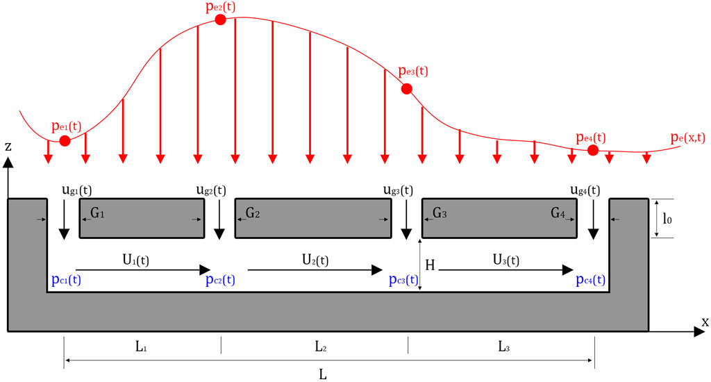
Figure 1. Definition sketch for a typical air-permeable multilayer residential cladding system with four idealized openings, assuming an air-impermeable inner sheathing layer.
The interaction between the external and cavity pressures is called pressure equalization, which is the mechanism whereby the pressures on the external building surfaces are partially transmitted through air-permeable outer layers to interior layers (Kumar, 2000). This is often defined as a pressure equalization factor (
The objective of this paper is to provide a framework for design wind loads for air-permeable multilayer systems, taking into consideration the effective area of the cladding; and to synthesize the currently available literature on pressure equalization factors. To do this, the pressure equalization values from previous studies on different building products are extracted and analyzed. Then, based on these values and the factors that govern them, a design guideline for determining the pressure equalization on typical air-permeable multilayer systems is provided. This paper is mostly concerned with air-permeable multilayer cladding systems that are present on low-rise, North American, residential buildings. While many of these results will hold for other applications, caution should be taken to ensure the results are appropriate. For example, rainscreen walls on high-rise buildings may have different internal geometry (e.g., Kumar, 2000) or some systems such as roof-mounted arrays may experience wind-induced resonance (Estephan et al., 2022).
Killip and Cheetham (1984), Fazio and Kontopidis (1988), Baskaran and Brown (1992), and Xie et al. (1992) were some of the first studies to attempt developing an analytical model for pressure equalization by using the discharge equation of flow through small openings, while assuming the flow was incompressible. Van Schijndel and Schols (1988) and Burgess (1995) took these a step further by incorporating the ideal gas law into these equations.
The models were then further developed by Inculet and Davenport (1994), Choi and Wang (1998) and Kumar and Van Schjindel (1999) by introducing unsteadiness through the Helmholtz resonator model developed by Holmes (1979) and Vickery (1986). Although these models match the experimental data, they could only consider a spatially uniform external pressure with a single opening. The models for cavity pressures were also improved by Amano et al. (1988), Trung et al. (2010), and Lou et al. (2012) by including the discharge model with spatially varying cavity pressures.
Although the discharge equation has been widely used to model flow through an opening by multiple studies (Sharma and Richards, 1997; Oh et al., 2007; Kopp et al., 2008; Ginger et al., 2010), it does not consider the viscous effects in the cavity flow. This is critical because cavities in air-permeable multilayer systems tend to be thin and long, which would amplify the role that viscous effects have. Sun and Bienkiewicz (1993) attempted to incorporate viscous effects into the pressure distributions in the cavity by using Darcy’s Law. However, this model is only for the mean flow (or steady flows with low turbulence).
Kumar et al. (2000) noted that continuous cavities are not always efficient, and that compartmentalization improves pressure equalization. If the cavity is divided into compartments, it could reduce the external pressure gradients and the flow between the adjacent cavities would be minimized. This would improve pressure equalization by reducing the flow in the cavity and, therefore, reduce the overall net load on the cladding. Furthermore, a study from Morrison Hershfield Ltd. (1990) suggested that compartmentalization should be required at the corners of buildings using a vinyl siding clad wood-framed wall. Doing this can reduce the pressure drop across the inner surface as well as the volume of air required for equalization, reducing the response time of cavity pressures.
Figure 2 shows a model for a cavity with one panel and two openings developed by Oh and Kopp (2014). Assuming that the flow through the gap is like an orifice flow, the flow in the cavity is unsteady Couette flow, and the cavity pressures are formed by this series of pressure drops, the formula for flow between two parallel plates as a function of time (
where
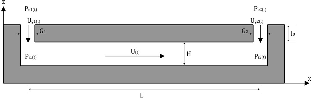
Figure 2. Pressure model of a flow in a double-layer system with two openings.
Solving these equations allows for a calculation of the cavity pressures in a system, which in turn allows for a calculation of the pressure equalization factor. An issue with this method is that it requires a consistent G/H ratio, along with a knowledge of hard-to-measure variables such as the effective length of the fluid passing though the gap and the average velocity of flow in the gap. However, these equations can be simplified to examine the critical geometric parameters that influence pressure equalization.
Assuming negligible friction losses at the openings (i.e.,
Oh and Kopp (2015) determined a parameter that controls the cavity pressure distribution by defining it as the ratio of losses across the air-permeable layer (Eq. 4) over the losses along the cavity (Eq. 5), or:
where
This transition from varying cavity pressures to uniform cavity pressures is what decreases the peak cavity pressure suction, causing the increase in pressure equalization.
Overall, these analytical models demonstrate the critical parameters that control the cavity pressure distribution and, therefore, the pressure equalization of air-permeable multilayer cladding. The geometric parameters are the gap width, the height of the cavity, as well as the length of the panel, which plays a role in ratio of the loss coefficient of the flow through the gaps and cavity.
Model-scale wind tunnel measurements have been a critical tool to developing the knowledge about pressure equalization, notably in the area of loose-laid roof pavers and solar panels. However, cladding with small gap openings (e.g., vinyl siding, shingles, discontinuous metal roofing) cannot be tested at model-scale due to errors created by scaling. Proper scaling is necessary to capture flow behavior over entire structures (Gerhardt and Jansen, 1994; Oh and Kopp, 2014; Kopp, 2023). Applying these length scales, which are typically 1/100 to 1/500, means cavity depths cannot be manufactured accurately (for example, a cavity depth of 1 mm at a 1/100 scale is practically impossible to manufacture). The gaps and openings in the cladding have a similar scaling problem and are not manufacturable. In addition, scaling down cavities behind the cladding can result in Reynolds number effects where cavity air flow is forcibly laminar, which may alter the overall net load on the cladding (Cheng and Melbourne, 1988; Gerhardt and Jansen, 1994).
Gerhardt and Jansen (1994) highlighted these issues by conducting wind tunnel tests on a scaled building with cladding. They showed that the full-scale field measurements did not match the wind tunnel testing and commented it was likely due to sensitivity in gap flow resistance between the scale model and the full-scale measurements. Cheung and Melbourne (1988) examined the size of the gaps of the cladding and cavity volume, and the role they play in the net load on air-permeable multilayer cladding systems. They showed that increasing the size of the gaps in cladding or increasing viscous effects in the cavity can decrease the net pressure. Kala et al. (2008) conducted a similar wind tunnel study on rainscreen walls in order to examine the parameters affecting pressure equalization. Van Bentum et al. (2012) also conducted wind tunnel tests on a 600 mm cube, with cladding of varying depths that were open at the edges only. They showed that the smallest cavity depth resulted in the highest net pressure. However, this is likely inaccurate as mentioned by the authors due to the openings being at corners only, as well as the scaling issues mentioned in the previous paragraph.
One of the first model-scale studies to examine how the pressure equalizes was Kind and Wardlaw (1982) who conducted a study to examine the failure (lifting/overturning) of roof pavers. They showed that the net wind loads on the pavers are much lower than the external pressure on an air-impermeable roof. These lower loads reduced the chance of failure of the pavers. This study was furthered by Kind (1988) to predict the wind speeds that caused failures of the roof pavers. However, Okada and Okabe (1991) showed that cavity depth can decrease the failure load of the pavers if the cavity depth is too large.
(Bienkiewicz and Sun 1992, Bienkiewicz and Sun, 1997) also conducted model-scale wind tunnel tests on a flat roof with pavers, comparing the net pressures on the pavers when there was no cavity, compared to a small cavity. This study showed that increasing the cavity depth resulted in a more uniform cavity pressure distribution, which reduced the pressure equalization and increased the net loads. It also showed that reducing the spacing between the pavers had a similar effect. Bienkiewicz and Endo (2009) also conducted a similar study to try and account for the effect of the gap between pavers on the net load on the pavers. They showed that the overall net loads on the pavers is dependent on the permeability of the outer layers (i.e., permeability increases when the gaps between the pavers is larger).
The previously mentioned paver studies were all conducted at a 1:25 scale, but Mooneghi et al. (2014) conducted a 1:2 scale model of roof pavers using the Wall of Wind facility on a small building. This study tested different ratios of the gaps between the pavers over the depth of the cavity (G/H). The results show that increasing the G/H ratio resulted in lower mean and peak net loads on the pavers, as well as also showing that the cavity pressure is uniform at low G/H ratios.
Pressure equalization is also critical for developing design wind loads for solar panels. As solar panels have become increasingly popular to install on roofs of buildings, there has been a lot of research to determine the wind loading mechanisms on these panels. Ginger et al. (2011) examined the effect that roof slope has on the net loads of solar panels when they are parallel to the roof. The results showed that the cavity depth did not play a role in the net loads on the solar panels. However, the solar panel was assumed to be one large array with no gaps in a large panel. Similar studies were also conducted by Stenabaugh et al. (2010) and Aly and Bitsuamlak (2014), which determined that with no gaps between the panels, the net loads on the panels were like the external loads on a bare roof surface. (Kopp et al., 2012, Kopp 2013) examine array geometry and their effect on the net load of the panels. They showed that the mechanism that governed the net load depended on the tilt angle of the panels. Panels were governed by pressure equalization when they were either parallel to the roof, or with a low tilt. The studies also showed that the spacing of the row and the height above the roof surface had minimal impact for the geometries examined.
Stenabaugh et al. (2015) examined the role that the G/H ratio has on the net loads on solar panels. It was shown that a high G/H ratio lowered the net loading on solar panels, and consequently
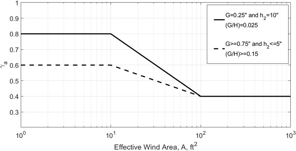
Figure 3. Pressure equalization factor as a function of effective wind area for solar panels (based on Figure 29.4-8 in ASCE 7-22, 2022).
Section 29.4.4 in ASCE 7-22 also gives guidelines on an array edge factor,
The main findings of these model-scale studies are that the geometric ratio of the gap size to the cavity depth (G/H) is an important parameter in determining the pressure equalization on air-permeable multilayer system. In other words, the ratio of the resistance of the orifice flow (i.e., through the gaps in the cladding) to the cavity flow (i.e., between the cladding and the interior layers on the wall or roof surface) has a strong effect on pressure equalization.
Field measurements are not typically used to determine peak net loads on air-permeable multilayer cladding for design. Rather, these studies tend to use differential pressure measurements through cladding to calculate ventilation for moisture and frost accumulation studies (e.g., Uvslokk, 1996; Straube, 1999). These types of studies are not used for design wind loads since they are not concerned with capturing high wind conditions. However, Gerhardt and Jansen (1994) instrumented cladding panels on an office building to compare pressure equalization on regular panels versus panels that had the cavities sealed on the vertical edges. This study showed that the modified panels increased pressure equalization (i.e., reduced wind loads) due to compartmentalization. Geurts and Blackmore (2013) also instrumented a solar panel in the field to provide estimates of the wind loading on these systems.
Recently, full-scale laboratory measurements have been utilized for pressure equalization studies due to the ability to resolve the scaling issues of cladding with small gaps and openings. Gavanski and Kopp (2012) tested vinyl siding in a similar airbox chamber system to the one set out by the ASTM D5206 (2013) standard. It was determined from that study that pressure equalization occurs across the air-permeable wall layers and substantially increases the ultimate capacity of the wall system. More specifically, vinyl siding equalizes almost perfectly and sees little to no net load when a uniform pressure is applied. This study by Gavanski and Kopp (2012) also obtained similar net loads from static, uniform airbox tests conducted by Architectural Testing Inc. (ATI, 2002). However, real buildings have significant pressure gradients over the external surfaces. To deal with this, Miller et al. (2017) developed a multichambered airbox system capable of applying spatially varying pressures across vinyl siding. They demonstrated that the design net loads for PVC siding systems as laid out in ASTM D3679-13 (2013) are unconservative (unsafe) due to the design net loads being based on testing with a uniform pressure across the wall, rather than using a more realistic spatial gradient across the wall. The main limitation of the Miller et al. (2017) method is the lack of clarity of what type of spatial gradients are appropriate for determining design values.
The Insurance Institute for Business and Home Safety (IBHS) Research Center (Cope et al., 2012; Cope et al., 2014; Morrison and Cope, 2015), tested PVC siding in a full-scale wind tunnel and indicated that the obtained net loads are more than double those of ASTM D3679-13 (2013), all else being equal. Moravej et al. (2016) also measured differential pressures across vinyl siding using the Wall of Wind facility at Florida International University. Net pressures were calculated by comparing the peak external pressure along with cavity pressure coefficients, which led to low net pressure coefficients due to the values not being coincident with each other. The instantaneous net loads were also calculated over a tributary area. These values matched closely with the study done by Cope et al. (2012). All of these studies demonstrate that the standard (ASTM D3679-13, 2013) at that time was underestimating design wind loads for PVC siding. Since Morrison and Cope (2015), Moravej et al. (2016), and Miller et al. (2017) have been published, ASTM D3679-13 (2013) has been updated to require a higher net load for PVC siding (ASTM D3679-21, 2021). However, this value is still 46% lower than the peak data obtained from the above studies on the pressure equalization on vinyl siding.
Miller et al. (2020) examined the aerodynamics of air-permeable multilayer cladding through full-scale wind tunnel testing at IBHS. This study showed that the net loads at design-level external wind loads are relatively unaffected by load level and wind direction. Finally, it demonstrated that there is a time lag between the peak external and cavity pressures, caused by the fluid inertia of the system. This inertial term desynchronizes the peak external and cavity pressures, reducing the peak net loads.
Full-scale measurements have also been performed on rainscreen wall systems (Stathopoulos, 1981). Similar testing done by Kumar et al. (2000) has shown that there are discrepancies between the codes for loads on rainscreen walls and the results obtained in these studies.
The literature review demonstrates that the physics that cause pressure equalization in air-permeable multilayer cladding systems are challenging to reconcile for codification purposes. While many studies have been done on pressure equalization, there is no current consensus on what equations or methods should be used to calculate the
Miller et al. (2020) tested two types of discontinuous metal roofing products, which have significantly different cavity geometries. The results from that study show that both products have similar ratios between the net and external wind loads. This suggests that design values have the potential to be relatively simple for typical residential building products, despite the fairly complex aerodynamics. Miller et al. (2020) also showed that this generally holds for systems having small openings into the cavity with relatively large cavity volumes, which leads to relatively uniform pressure along the cavity. The remainder of this section discusses a definition of the pressure equalization factor (
This section gives a brief summary of the definitions used for pressure equalization factors with the intent of providing guidelines for one that can be used to synthesize multiple full-scale studies on air-permeable multilayer cladding. ASCE 7-22 (2022) defines the external pressure coefficients as a peak value across all locations in a zone (
For consistency with current enveloping methods for the external pressure coefficient, it is recommended to envelope the net pressure in a similar fashion to Eq. 8. Keeping the simple definition of pressure equalization factor from earlier - “the proportion of external load acting on the cladding element”, Geurts (2000) proposed such a non-simultaneous pressure equalization coefficient, as the ratio of the largest magnitude value of the peak net pressure at any point in time over the largest magnitude value of the peak external pressure at any point in time, across all wind directions, i.e.,
This method is already currently used in ASCE 7-22 (2022) for determining the pressure equalization in solar panels (Stenabaugh et al., 2015). Enveloping the worst-case value for each effective area is a common method of obtaining design wind loads on components and cladding (Stathopoulos et al., 2000; Morrison and Kopp, 2018). The downside of this approach is that design loads are a step removed from the equations and numerical models used to calculate cavity pressures in air-permeable multilayer systems. For the current study, this definition Eq. 9 of the pressure equalization coefficient is what is used for the analysis. However, it is also useful to define Eq. 10
which is the peak magnitude pressure equalization coefficient for a single cladding element at a location,
Several statistical methods to define the peak pressure coefficient (
The Supplementary Material contains a review of studies that have published values for the
Using data from the Supplementary Material, Figure 4 presents
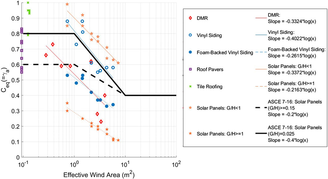
Figure 4.
Although it is clear that the differing geometry between the types of air-permeable multilayer cladding is causing some differences in the data, the figure shows that the
The introduction of this paper explored the idea that the geometry of air-permeable multilayer systems is often hard to define. However, the literature on air-permeable multilayer systems has shown that the G/H ratio is an important geometric ratio for determining the pressure equalization in a system (Oh and Kopp, 2014; Stenabaugh et al., 2015). Stenabaugh et al. (2015) compared the pressure equalization coefficient (
Using the data from Stenabaugh (2015) and Mooneghi et al. (2015), Figure 5 presents a plot of the
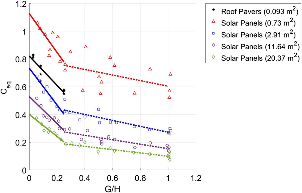
Figure 5.
However, for materials like vinyl siding, foam-backed vinyl siding, discontinuous metal roofing, and potentially other air-permeable multilayer systems, it is extremely difficult, perhaps impossible, to calculate this ratio. Recommendations for determining an effective G/H ratio
Panel size is a critical factor in determining the effect of pressure equalization on air-permeable multilayer cladding systems. This is because, as the panel size increases, the peak external pressure remains the same but the peak cavity pressure suction decreases, which increases
The dataset currently presented in this section is not robust enough to perform an analysis of the panel size vs.
The flow fields in which air-permeable multilayer cladding systems are installed are complex, influenced by both the building and the geometry of the cladding. Flow separation from the building edges creates regions of large suctions on the roof. Downstream the flow reattaches with reduced pressure magnitudes. This pressure gradient around the perimeter of a roof is addressed in building codes by zoning the roof such that corner and edge zones are assigned larger magnitude wind pressure coefficients due to the separated flow (Morrison and Kopp, 2018). If unsealed air-permeable multilayer cladding is installed around the perimeter of the roof in the region of separated flow they could be subject to localized pressure gradients. This yields higher magnitude wind-induced pressures on edge modules of the array; herein referred to as the roof edge effect. These higher pressures on the edges of unsealed air-permeable multilayer cladding have been noted in previous full-scale wind tunnel studies (Smith and Morrison, 2019; Tolera et al., 2022).
As an example, roof-mounted solar modules are typically mounted at some height above the roof surface. This could be considered to be similar to a cavity depth but could potentially be much larger than other system types, depending on the installation methods used. Their protrusion from the (bare) roof surface can cause a secondary region of flow separation along the leading edge of the array. This can lead to a pressure gradient on perimeter modules; herein referred to as the array edge effect. The relative dimensions associated with the array edge effect are not clearly defined but are likely a function of the cavity depth and the module thickness.
Individual modules within the array can be subject to roof edge effects, array edge effects or both. This exposed edge effect is accounted for in ASCE 7-22 (2022), where Figure 29.4-7 gives guidelines on an array edge factor,
Conversely, on certain types of air-permeable multilayer systems such as roof pavers, it is common to install parapets along the edges of the roof. These parapets provide sheltering from the worst turbulent flow at the corners and edges of the roof. Therefore, parapets have a reducing effect on the overall net load considered on a system. Mooneghi et al. (2015) examined the relationship between the parapet height (normalized by the eave height), and the peak
This section (although conservative and simplified) provides design guidelines for calculating the pressure equalization factor (and consequently the net load) of typical air-permeable multilayer systems. These guidelines could then be used to alter equation 29.4-7 in ASCE 7 so that the net pressure can be obtained for any air-permeable multilayer system rather than just solar panels mounted parallel to a roof, i.e.,:
where
where
The effective area factor accounts for the effect that the effective wind area has on the pressure equalization factor. Because of the enveloping method used in this analysis,
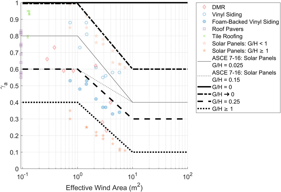
Figure 6. Recommended design guidelines for the pressure equalization of air-permeable multilayer systems, accounting for the effective area and the G/H ratio.
The other two design lines are for systems with a G/H ratio of 0.25, and systems with a G/H ratio of 1 or larger. The four design lines were chosen for those specific G/H ratios in order to be able to linearly interpolate between 0 and 0.25, as well as 0.25 to 1, to coincide with the trendlines detailed in Figure 5. All of the design lines remain constant at an effective wind area equal to or larger than 10 m2. This is because no data are available for air-permeable multilayer systems with an effective wind area that large, except for the current ASCE 7-22 guidelines on solar panels. This could be further refined in the future by obtaining data with larger effective wind areas. Similarly, all design lines remain constant at an effective wind area equal to or smaller than 1 m2. This cut-off has practical value in terms of expressing the maximum
As mentioned earlier, the G/H ratio for air-permeable systems with small gap widths and small cavity depths can be challenging to measure. A proposed guideline to deal with this challenge is to use the data presented in Figure 4 to determine which G/H curve is appropriate for each type of air-permeable multilayer system by using linear interpolation of the design graphs presented in Figure 6. This could be defined as an effective G/H ratio, or
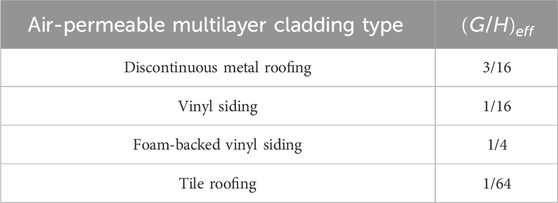
Table 1. Effective G/H ratio for air-permeable multilayer cladding systems.
These
The panel size factor (
Although there have been individual studies done on pressure equalization, there is no current consensus on what methods should be used to calculate the
Pressure equalization studies on air-permeable multilayer systems (discontinuous metal roofing, vinyl siding, roof pavers, tile roofing, and solar panels) were examined in order to develop design guidelines for air-permeable multilayer systems. The
By synthesizing these studies and considering the factors that affect
The original contributions presented in the study are included in the article/Supplementary Material, further inquiries can be directed to the corresponding author.
CM: Conceptualization, Data curation, Formal Analysis, Investigation, Methodology, Software, Validation, Visualization, Writing–original draft. GK: Funding acquisition, Project administration, Resources, Supervision, Writing–review and editing.
The author(s) declare that financial support was received for the research, authorship, and/or publication of this article. This work was funded by the Natural Sciences and Engineering Research Council (NSERC) of Canada through the Collaborative Research and Development Program and the Institute for Catastrophic Loss Reduction.
The authors would like to thank Dr. Murray Morrison and Dr. Randy Van Straaten for their extensive discussions on pressure equalization, which influenced the direction and content of this study.
The authors declare that the research was conducted in the absence of any commercial or financial relationships that could be construed as a potential conflict of interest.
The author(s) declared that they were an editorial board member of Frontiers, at the time of submission. This had no impact on the peer review process and the final decision
All claims expressed in this article are solely those of the authors and do not necessarily represent those of their affiliated organizations, or those of the publisher, the editors and the reviewers. Any product that may be evaluated in this article, or claim that may be made by its manufacturer, is not guaranteed or endorsed by the publisher.
The Supplementary Material for this article can be found online at: https://www.frontiersin.org/articles/10.3389/fbuil.2024.1398472/full#supplementary-material
Aly, A., and Bitsuamlak, G. (2014). Wind-induced pressures on solar panels mounted on residential homes. J. Arch. Eng. 20 (1), 4013003. doi:10.1061/(ASCE)AE.1943-5568.0000132
Amano, T., Fujii, K., and Tazaki, S. (1988). Wind loads on permeable roof-blocks in roof insulation systems. J. Wind Eng. Ind. Aerodyn. 29, 39–48. doi:10.1016/0167-6105(88)90143-2
American Society for Civil Engineering (2022). Asce 7-22: minimum design loads for buildings and other structures. doi:10.1061/9780784415788
Architectural Testing, Inc. (2002). Wind pressure equalization research Project report. Washington, DC: 01 for the Vinyl Siding Institute. No. 01-40776.
ASTM D3679-13 (2013). Standard specification for rigid poly (vinyl chloride) (PVC) siding. West Conshohocken, PA: ASTM International. doi:10.1520/D3679-13
ASTM D3679-21 (2021). Standard specification for rigid poly (vinyl chloride) (PVC) siding. West Conshohocken, PA: ASTM International. doi:10.1520/D3679-21
Baskaran, B., and Brown, W. (1992). Performance of pressure equalized rainscreen walls under cyclic loading. J. Therm. Enve. Build. Sci. 16, 183–193. doi:10.1177/109719639201600209
Bienkiewicz, B., and Endo, M. (2009). “Wind considerations for loose-laid and photovoltaic roofing systems,” in 2009 structures congress -don't mess with structural engineers: expanding our role (Reston, VA: American Society of Civil Engineers), 2578–2587. doi:10.1061/41031(341)282
Bienkiewicz, B., and Sun, Y. (1992). Wind-tunnel study of wind loading on loose-laid roofing systems. J. Wind Eng. Ind. Aerodyn. 41-44, 1817–1828. doi:10.1016/0167-6105(92)90599-6
Bienkiewicz, B., and Sun, Y. (1997). Wind loading and resistance of loose-laid roof paver systems. J. Wind Eng. Ind. Aerodyn. 72, 401–410. doi:10.1016/S0167-6105(97)00235-3
Burgess, J. C. (1995). Air pressure equalization in rainscreened joints by geometric alteration. Build. Env. 30, 13–18. doi:10.1016/0360-1323(93)E0007-Z
Cheung, J. C. K., and Melbourne, W. H. (1988). Wind loading on a porous roof. J. Wind Eng. Ind. Aerodyn. 29, 19–28. doi:10.1016/0167-6105(88)90141-9
Choi, E., and Wang, Z. (1998). Study on pressure-equalization of curtain wall systems. J. Wind Eng. Ind. Aerodyn. 73, 251–266. doi:10.1016/S0167-6105(97)00290-0
Cope, A. D., Crandell, J. H., Johnston, D., Kochkin, V., Liu, Z., Stevig, L., et al. (2012). “Wind loads on components of multi-layer wall systems with air-permeable exterior cladding,” in Proceedings of the ATC-SEI Advances in Hurricane Engineering Conference, Miami, FL, October 24-26, 2012.
Cope, A. D., Crandell, J. H., Liu, Z., and Stevig, L. (2014). Wind loads on fasteners used to attach flexible porous siding on multi-layer wall systems. J. Wind Eng. Ind. Aerodyn. 133, 150–159. doi:10.1016/j.jweia.2014.06.007
Estevan, J., Chowdhury, A. G., and Irwin, P. (2022). A new experimental-numerical approach to estimate peak wind loads on roof-mounted photovoltaic systems by incorporating inflow turbulence and dynamic effects. Eng. Struct. 252, 113739. doi:10.1016/j.engstruct.2021.113739
Fazio, P., and Kontopidis, T. (1988). Cavity pressure in rainscreen walls. Build. Env. 23, 137–143. doi:10.1016/0360-1323(88)90027-3
Gavanski, E., Gurley, K. R., and Kopp, G. A. (2016). Uncertainties in the estimation of local peak pressures on low-rise buildings by using the Gumbel distribution fitting approach. J. Struct. Eng. 142, 11. doi:10.1061/(ASCE)ST.1943-541X.0001556
Gavanski, E., and Kopp, G. A. (2012). Effects of pressure equalization on the performance of residential wall systems under extreme wind loads. J. Struct. Eng. 138, 526–538. doi:10.1061/(ASCE)ST.1943-541X.0000476
Gerhardt, H. J., and Jansen, F. (1994). Wind loads on wind permeable facades. J. Wind Eng. Ind. Aerodyn. 53, 37–48. doi:10.1016/0167-6105(94)90017-5
Geurts, C. (2000). “Wind loads on permeable roof covering products,” in Fourth colloquium on bluff body aerodynamics and applications (Bochum, Germany: Rufr Universitat).
Geurts, C., and Blackmore, P. (2013). Wind loads on stand-off photovoltaic systems on pitched roofs. J. Wind Eng. Ind. Aerodyn. 123, 239–249. doi:10.1016/j.jweia.2013.08.016
Ginger, J., Payne, M., Stark, G., Sumant, B., and Leitch, C. (2011). Investigation on wind loads applied to solar panels mounted on roofs. Townsville, Australia: Cyclone Testing Station.
Ginger, J. D., Holmes, J. D., and Kim, P. Y. (2010). Variation of internal pressure with varying sizes of dominant openings and volumes. J. Struct. Eng. 136 (9), 1319–1326. doi:10.1061/(ASCE)ST.1943-541X.0000225
Holmes, J. D. (1979). “Mean and fluctuating internal pressure induced by wind,” in Proceedings of the fifth international conference on wind engineering. Colorado, United States: (Colorado State University), 435–450. doi:10.1016/B978-1-4832-8367-8.50046-2
Inculet, D. R., and Davenport, A. G. (1994). Pressure-equalized rainscreens: a study in the frequency domain. J. Wind Eng. Ind. Aerodyn. 53, 63–87. doi:10.1016/0167-6105(94)90019-1
ISO 4354 (2009). Wind actions on structures. Geneva, Switzerland: International Organization for Standardization. Available at: www.iso.org.
Kala, S., Stathopoulos, T., and Suresh Kumar, K. (2008). Wind loads on rainscreen walls: boundary layer wind tunnel experiments. J. Wind Eng. Ind. Aerodyn. 96 (6-7), 1058–1073. doi:10.1016/j.jweia.2007.06.028
Killip, I. R., and Cheetham, D. W. (1984). The prevention of rain penetration through external walls and joints by means of pressure equalization. Build. Env. 19, 81–91. doi:10.1016/0360-1323(84)90033-7
Kind, R. (1998). Worst suctions near edges of flat rooftops with parapets. J. Wind Eng. Ind. Aerodyn. 31, 251–264. doi:10.1016/0167-6105(88)90007-4
Kind, R., and Wardlaw, R. (1982). Failure mechanisms of loose-laid roof-insulation systems. J. Wind Eng. Ind. Aerodyn. 9, 325–341. doi:10.1016/0167-6105(82)90022-8
Kopp, G. A. (2013). Wind loads on low profile, tilted, solar arrays placed on large, flat, lowrise building roofs. J. Struct. Eng. 140 (2), 04013057. doi:10.1061/(ASCE)ST.1943-541X.0000825
Kopp, G. A. (2023). Updates to the wind tunnel method for determining design loads in ASCE 49-21. Wind Struct. 37 (2), 163–178. doi:10.12989/was.2023.37.2.163
Kopp, G. A., Farquhar, S., and Morrison, M. J. (2012). Aerodynamic mechanisms for wind loads on tilted, roof-mounted, solar arrays. J. Wind Eng. Ind. Aerodyn. 111, 40–52. doi:10.1016/j.jweia.2012.08.004
Kopp, G. A., Oh, J. H., and Inculet, D. R. (2008). Wind-induced internal pressures in houses. J. Struct. Eng. 134 (7), 1129–1138. doi:10.1061/(ASCE)0733-9445(2008)134:7(1129)
Kumar, K. (2000). Pressure equalization of rainscreen walls: a critical review. Build. Env. 35, 161–179. doi:10.1016/S0360-1323(99)00015-3
Kumar, K., and Van Schijndel, A. (1999). Prediction of pressure equalization performance of rainscreen walls. Wind Struct. 2 (4), 325–345. doi:10.12989/was.1999.2.4.325
Lieblein, J. (1974). Efficient methods of extreme-value methodology. Washington, DC: National Bureau of Standards, 74–602. NBSIR.
Lou, W., Huang, M., Zhang, M., and Lin, N. (2012). Experimental and zonal modeling for wind pressures on double-skin facades of a tall building. Ener Build. 54, 179–191. doi:10.1016/j.enbuild.2012.06.025
Miller, C. S., Kopp, G. A., and Morrison, M. J. (2020). Aerodynamics of air-permeable multilayer roof cladding. J. Wind Eng. Ind. Aerodyn. 207, 104409. doi:10.1016/j.jweia.2020.104409
Miller, C. S., Kopp, G. A., Morrison, M. J., Kemp, G., and Drought, N. (2017). A multichamber, pressure-based test method to determine wind loads on air-permeable, multilayer cladding systems. Front. Built Env. 3, 7. doi:10.3389/fbuil.2017.00007
Mooneghi, M., Irwin, P., and Chowdhury, A. G. (2014). Large-scale testing on wind uplift of roof pavers. J. Wind Eng. Ind. Aerodyn. 128, 22–36. doi:10.1016/j.jweia.2014.03.001
Mooneghi, M., Irwin, P., and Chowdhury, A. G. (2015). Towards guidelines for design of loose-laid roof pavers for wind uplift. Wind Struct. 22 (2), 133–160. doi:10.12989/was.2016.22.2.133
Moravej, M., Zisis, I., Chowdhury, A., Irwin, P., and Hajra, B. (2016). Experimental assessment of wind loads on vinyl wall siding. Front. Built Env. 2, 35. doi:10.3389/fbuil.2016.00035
Morrison, H. L. (1990). A study of the rainscreen concept applied to cladding systems on wood frame walls, Canada Mortgage and Housing Corporation, Technical Series 96-214.
Morrison, M. J., and Cope, A. D. (2015). “Wind performance and evaluation methods of multi-layered wall assemblies,” in Proceeding of ASCE structures congress. Portland, OR. doi:10.1061/9780784479117.237
Morrison, M. J., and Kopp, G. A. (2018). Effects of turbulence intensity and scale on surface pressure fluctuations on the roof of a low-rise building in the atmospheric boundary layer. J. Wind Eng. Ind. Aerodyn. 183, 140–151. doi:10.1016/j.jweia.2018.10.017
Oh, J. H., and Kopp, G. A. (2014). Modelling of spatially and temporally-varying cavity pressures in air permeable, double-layer roof systems. Build. Env. 82, 135–150. doi:10.1016/j.buildenv.2014.08.008
Oh, J. H., and Kopp, G. A. (2015). An experimental study of pressure distributions within an air-permeable, double-layer roof system in regions of separated flow. J. Wind Eng. Ind. Aerodyn. 138, 1–12. doi:10.1016/j.jweia.2014.12.006
Oh, J. H., Kopp, G. A., and Inculet, D. R. (2007). The UWO contribution to the NIST aerodynamic database for wind loads on low buildings: part 3. Internal pressures. J. Wind Eng. Ind. Aerodyn. 95, 755–779. doi:10.1016/j.jweia.2007.01.007
Okada, H., and Okabe, M. (1991). Wind tunnel tests to determine the wind forces on roof blocks for existing buildings. J. Wind Eng. Ind. Aerodyn. 38, 393–403. doi:10.1016/0167-6105(91)90057-4
Sadek, F., and Simiu, E. (2002). Peak non-Gaussian wind effects for database-assisted low-rise building design. J. Eng. Mech. 128 (5), 530–539. doi:10.1061/(ASCE)0733-9399(2002)128:5(530)
Sharma, R. N., and Richards, P. J. (1997). Computational modelling of the transient response of building internal pressure to a sudden opening. J. Wind Eng. Ind. Aerodyn. 72, 149–161. doi:10.1016/S0167-6105(97)00244-4
Smith, D. J., and Morrison, M. J. (2019). “Full-scale wind tunnel testing of North American and Australian roofing tile systems,” in Proceedings of the 15th International Conference on Wind Engineering, Beijing, China, September 1-6, 2019.
Stathopoulos, T. (1981). Discussion of Load distribution and double skin wall. J. Struct. Div. ST10, 2048–2049. doi:10.1061/JSDEAG.0005806
Stathopoulos, T., Wang, K., and Wu, H. (2000). Proposed new Canadian wind provisions for the design of gable roofs. Can. J. Civ. Eng. 27 (5), 1059–1072. doi:10.1139/l00-023
Stenabaugh, S. E. (2015). Design wind loads for solar modules mounted parallel to the roof of a low-rise building. Electronic thesis and dissertation repository, 2817. Available at: https://ir.lib.uwo.ca/etd/2817.
Stenabaugh, S. E., Iida, Y., Kopp, G. A., and Karava, P. (2015). Wind loads on photovoltaic arrays mounted parallel to sloped roofs on low-rise buildings. J. Wind Eng. Ind. Aerodyn. 139, 16–26. doi:10.1016/j.jweia.2015.01.007
Stenabaugh, S. E., and Karava, P. (2010). “Design wind loads for photovoltaic systems on sloped roof of residential buildings,” in Proceeding of ICWE13, Amsterdam, Netherlands, September 15, 2010.
Straube, J. F., and Burnett, E. (1999). Rain control and design strategies. J. Build. Phys. 23 (1), 41–56. doi:10.1106/XVJ7-XNGB-7WDQ-DY0U
Sun, Y., and Bienkiewicz, B. (1993). Numerical simulation of pressure distributions underneath roofing paver systems. J. Wind Eng. Ind. Aerodyn. 46-47, 517–526. doi:10.1016/0167-6105(93)90319-J
Tolera, A. B., Mostafa, K., Chowdhury, A. G., Zisis, I., and Irwin, P. (2022). Study of wind loads on asphalt shingles using full-scale experimentation. J. Wind Eng. Ind. Aerodyn. 225, 105005. doi:10.1016/j.jweia.2022.105005
Trung, V. T., Tamura, Y., and Yoshida, A. (2010). “Numerical computation for lower surfacepressures on a porous sunshade roof cover sheet,” in Proceedings of the 5th International Symposium on Computational Wind Engineering, Chapel Hill, North Carolina, USA, May 23-27, 2010.
Uvslokk, S. (1996). The importance of wind barriers for insulated timber frame constructions. J. Build. Phys. 20 (1), 40–62. doi:10.1177/109719639602000105
Van Bentum, C., Kalkman, I., and Geurts, C. (2012). “Towards a better understanding of pressure equalization,” in The seventh international colloquium on bluff body aerodynamics and applications. Shanghai, China.
Van Schijndel, A., and Schols, S. (1998). Modeling pressure equalization in cavities. J. Wind Eng. Ind. Aerodyn. 74-76, 641–649. doi:10.1016/S0167-6105(98)00058-0
Vickery, B. (1986). Gust factors for internal pressures in low-rise buildings. J. Wind Eng. Ind. Aerodyn. 23 (1), 259–271. doi:10.1016/0167-6105(86)90047-4
Keywords: wind loads, building aerodynamics, pressure equalization, air-permeable, cladding systems, full-scale experiments
Citation: Miller CS and Kopp GA (2024) A framework for design wind loads on air-permeable multilayer cladding systems. Front. Built Environ. 10:1398472. doi: 10.3389/fbuil.2024.1398472
Received: 10 March 2024; Accepted: 16 May 2024;
Published: 07 June 2024.
Edited by:
Seymour M. J. Spence, University of Michigan, United StatesReviewed by:
Mingfeng Huang, Zhejiang University, ChinaCopyright © 2024 Miller and Kopp. This is an open-access article distributed under the terms of the Creative Commons Attribution License (CC BY). The use, distribution or reproduction in other forums is permitted, provided the original author(s) and the copyright owner(s) are credited and that the original publication in this journal is cited, in accordance with accepted academic practice. No use, distribution or reproduction is permitted which does not comply with these terms.
*Correspondence: Connell S. Miller, Y29ubmVsbC5taWxsZXJAdXdvLmNh
Disclaimer: All claims expressed in this article are solely those of the authors and do not necessarily represent those of their affiliated organizations, or those of the publisher, the editors and the reviewers. Any product that may be evaluated in this article or claim that may be made by its manufacturer is not guaranteed or endorsed by the publisher.
Research integrity at Frontiers
Learn more about the work of our research integrity team to safeguard the quality of each article we publish.