 Liming Fan
 Zhilin Li
 Yongjiang Luo
94% of researchers rate our articles as excellent or good
Learn more about the work of our research integrity team to safeguard the quality of each article we publish.
Find out more
ORIGINAL RESEARCH article
Front. Built Environ., 18 June 2024
Sec. Geotechnical Engineering
Volume 10 - 2024 | https://doi.org/10.3389/fbuil.2024.1395464
This article is part of the Research TopicAdvances in Geomechanics Research and Application for Deep Unconventional ReservoirsView all 35 articles
The reverse circulation down-the-hole air hammer drilling (RC-DTH) method is renowned for its efficiency in hard rock formations and exceptional dust control performance. It presents opportunities for cost-saving, efficiency improvement, energy conservation, and environmental protection. Reverse circulation drill bits are critical components of this method. This study focused on the air reverse circulation regime, investigating various geometric parameters of the RC drill bits through computational and experimental methods to enhance its dust control performance. Results indicate that increasing the layers of suction nozzles, enlarging the diameters of the suction and mixing nozzles, and optimizing the input airflow rate can effectively channel airflow toward the central passage of the drill tool. Consequently, this optimization significantly improves the dust control performance of the RC drill bits. Conversely, increases in the flushing nozzle diameter and alterations in the suction nozzle location have detrimental effects on the dust control capability of the RC drill bits. Field tests were conducted at the Yuan Jiacun iron mine, affiliated with Taiyuan Iron and Steel (Group) CO., LTD. The field tests demonstrate that the optimized RC drill bit exhibits excellent dust performance.
Down-the-hole (DTH) air hammer drilling stands out as a premier method for hard rock drilling (Lyons et al., 2009). Its widespread adoption in various industries like mining, oil and gas, geothermal exploitation, and other drilling applications attests to its efficacy (Han et al., 2005; Deng et al., 2024). This technique offers several advantages, such as producing straighter boreholes, penetration without any drilling fluid, and lower bottom-hole pressure. Additionally, it finds utility in underbalanced drilling scenarios and proves beneficial in water-sensitive formations (Zhang et al., 2017). However, the prevalent use of DTH air hammer drilling tools presents a significant challenge in the form of respirable dust emissions (Organiscak and Page, 1995). Of particular concern is silica dust, classified as a carcinogen, with numerous studies underscoring the perils associated with prolonged exposure to it (Tavakol et al., 2016). Researchers have established a link between inhaling silica particles present in mining dust and the subsequent development of various respiratory ailments, including chronic obstructive pulmonary disease (COPD), emphysema, chronic bronchitis, and non-reversible asthma (Li et al., 2016). Overexposure to respirable silica can lead to severe health complications like lung cancer, silicosis, or other silica-related diseases, characterized by the formation of lesions on lung tissue, which impairs oxygen absorption (Cooper et al., 2012). Recognizing the hazards posed by silica dust, regulatory bodies like the Occupational Safety and Health Administration (OSHA) have instituted guidelines to safeguard workers, particularly in concrete-related industries, from silica dust exposure (Mixon and Nain, 2013). These regulations mandate mine owners to implement measures for monitoring silica dust levels, controlling dust dispersion on job sites, and shielding workers from airborne silica exposure. Given the critical imperative to mitigate dust production during drilling operations, proactive measures are paramount to ensure the safety and wellbeing of workers in these environments.
Several studies have investigated methods to reduce dust production during the drilling process using the DTH air hammer drilling method. Cecala et al. (2003) developed an enclosed cab with retrofitted filtration and pressurization systems to protect the drill operators from the drilling dust. However, while this system offers shelter to the workers inside the cab, personnel in the vicinity of the drilling operations and machinery remain exposed to dusty environments. Studies by Li et al. (2016) indicate that controlling drilling by adjusting the penetration and rotational rates can reduce respirable dust. However, sacrificing the penetration rate for dust reduction is not a practical solution. Wet drilling technology is widely regarded as the most effective method for dust control, boasting efficiencies of up to 96% (USBM, 1987). To effectively control dust, the amount of water injected must be adjusted based on the drill type, geology, and the original moisture level of the formation being drilled (Cecala et al., 2012). However, maintaining appropriate water injection levels poses the following challenges: too little water reduces dust control efficiency, while excessive water can lead to operational issues such as drill bit plugging and rotation binding due to agglomeration of drill cuttings (USBM, 1987). Additionally, wet drilling accelerates bit wear and shortens its lifespan by over 50% (Hustrulid, 1982; Page, 1991; Sundae et al., 1995). In dry drilling operations, the dust collection systems installed on the drill deck typically consist of hydro-cyclones with exhaust fans and filters. However, these systems often suffer from poor maintenance, resulting in damaged, non-functional, or missing dust collector filters, leading to dusty exhaust air emissions (Maksimovic and Page, 1985; Zimmer and Lueck, 1986; Zimmer et al., 1987). Other sources of emissions in the collection system can be attributed to damaged or worn enclosure components or operational conditions, hindering the containment and capture of dust.
Since the 1980s, the RC-DTH air hammer drill method has been developed to mitigate drill dust and enhance the penetration rates in fractured formations (Liu and Yin, 2012). The RC-DTH air hammer drill tool typically comprises a dual-passage faucet, dual-wall drill pipes, an RC-DTH air hammer, and an RC drill bit, as illustrated in Figure 1. A notable distinction between traditional rotary drilling and RC-DTH air hammer drilling methods lies in the circulation of discharged drill cuttings. In RC-DTH air hammer drilling, compressed air is injected into the annulus of dual-wall pipes, propelling the RC-DTH air hammer to deliver high-frequency blows to an RC drill bit, thereby forming reverse circulation. The exhaust air carrying drill cuttings returns to the surface through the central passage of dual-wall drill pipes instead of the annulus space between the drill pipes and the borehole wall. This drilling system effectively controls dust without water injection or additional borehole entrance attachments, presenting an environmentally friendly and cost-effective drilling technique. Although extensive studies on the dust control performance of RC drill bits have been documented in the literature, with reported dust control efficiencies of up to 99%, dust emissions may still occur during the initial drilling phase due to lower annular back pressure and inadequate reverse circulation capacity without proper design. Furthermore, air loss in fractured formations can exacerbate the dust control performance of this drilling system. To further enhance the dust control performance of RC drill bits and meet engineering requirements, the effects of the geometric parameters on the performance of a newly developed RC drill bit were investigated, and a field trial was conducted to validate its feasibility.
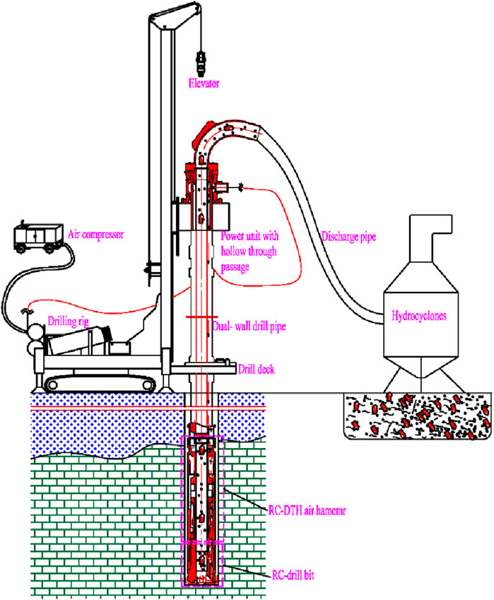
Figure 1. Schematic representation of the hollow-through DTH air hammer drilling system.
Figure 2 depicts the schematic representation of the RC drill bit. Following the operation of the DTH air hammer, compressed air exits through two passages: the suction nozzles positioned on the drill bit body and the flushing nozzles oriented perpendicular to the borehole bottom face. As compressed air flows through the suction nozzles, it forms jets at their outlets, creating a negative pressure zone nearby. The pressure differential between the borehole bottom and this negative pressure zone within the center passage generates a lifting force on the air, carrying drill cuttings. Furthermore, air entering the flushing nozzles serves to cool the bit inserts and direct the drill cuttings into the center passage. This synergistic process facilitates the formation of air reverse circulation without the need for any sealing elements. The dust control capability of the RC drill bit hinges on the mass flow rate of air drawn from the annulus between the drill pipes and the borehole. Greater air suction from the annular space into the center passage correlates with enhanced dust control performance and augmented reverse circulation capacity.
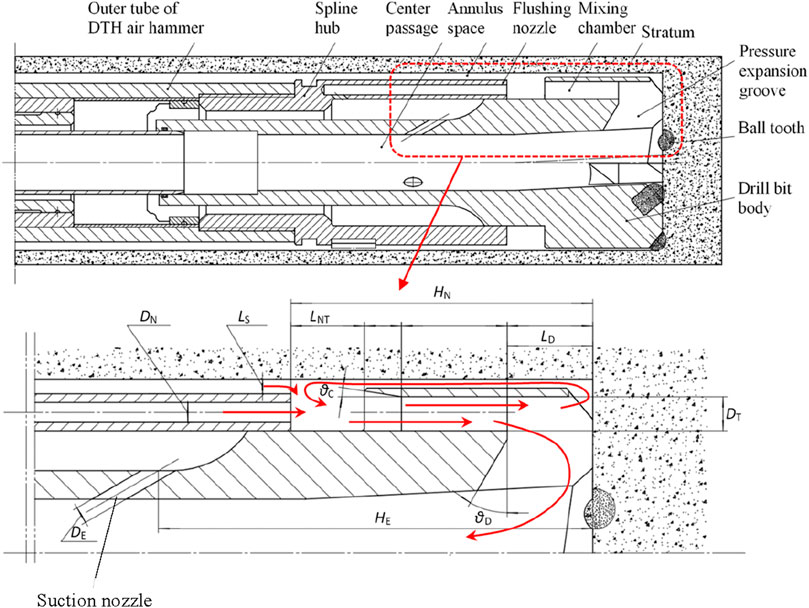
Figure 2. Schematic representation of the RC drill bit.
Orthogonal design was employed to optimize the dust control performance of the RC drill bit. The study investigated the effects of the geometric parameters, including the suction nozzle layer m), diameter (DE), and its location (HE); the flushing nozzle diameter (DN); the mixing nozzle diameter (DT); the size of the annulus between the drill bit and borehole wall (LS); the distance between the flushing nozzle and mixing nozzle (LNT); the throat angle of the mixing nozzle (
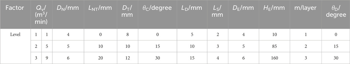
Table 1. Levels for each parameter employed by the numerical simulation.

Table 2. Levels for each parameter employed by the experiments.

Table 3. Orthogonal experimental design L27 (313) and results for the numerical simulation.

Table 4. Orthogonal experimental design L18 (2×37) and results for the experiments.
Computational domains were constructed using SolidWorks software and meshed with HyperMesh software. Figure 3 illustrates a typical computational domain with 2,571,513 grids, which are divided into eight parts. The regular parts were meshed with a structured grid, while the irregular parts utilized a tetrahedral grid. Pyramid grids were employed to ensure connectivity across all parts. The inlet face, situated in the annulus space of dual-wall drill tools, was designated as a mass-flow-inlet boundary, with the input mass flow rate adjusted based on the air compressor parameters. Outlet faces, located in the center passage and the annulus between the drill tool and borehole wall, were defined as pressure-outlet boundaries set to atmospheric pressure. No-slip stationary wall boundary conditions were applied to the remaining boundaries. The 3D continuity, momentum, and energy conservation equations governing compressible flow within the drill bit were solved using Ansys Fluent software. The k-ɛ turbulence model was employed to simulate turbulent flow, with second-order upwind discretization utilized for convective terms, turbulent kinetic energy function, and turbulent dissipation rate function. The coupling between velocity and pressure was managed using the SIMPLE (semi-implicit method for pressure-linked equations) algorithm.
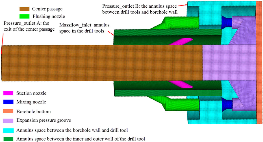
Figure 3. Typical meshed computational domain (the other half was masked).
A series of experiments were undertaken to validate the numerical simulation outcomes utilizing a specially designed experimental setup, as depicted in Figure 4. This apparatus was modularly designed to facilitate parameter adjustments according to the orthogonal design. The drill bit was segmented into four parts: the suction nozzle section, the flushing nozzle section, the mixing nozzle section, and the expansion pressure groove section. To monitor the system parameters, two flowmeters and three pressure gauges were incorporated to measure the volume flow rate and pressure, respectively. The experiments employed a piston air compressor with a nominal volume flow of 6 m³/min and a nominal pressure of 0.8 MPa. In total, 18 experiments were conducted.
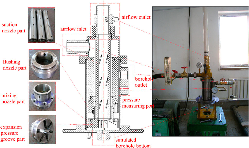
Figure 4. Apparatus for laboratory experiments.
A total of 27 computational models and 18 experiments were conducted based on an orthogonal design. The range analysis results yielded the order of each parameter. Among these parameters, the flushing nozzle diameter (DN) exhibited the most significant effect on the dust control capacity of the drill bit, followed by the input air volume rate (Qv), suction nozzle location (HE), mixing nozzle diameter (DT), distance between the flushing nozzle and mixing nozzle (LNT), suction nozzle layers (m), suction nozzle diameter (DE), the size of the annulus between the drill bit and borehole wall (LS), and the elevation angle of the expansion pressure groove. Differences were observed between the simulation and experimental results for both drill bit structures. These disparities could be attributed to machine errors and leaks in the experimental apparatus, which are unavoidable in laboratory settings. Additionally, despite the use of a surge tank to mitigate fluctuations, the input volume flow rate remained variable during experimentation. Conversely, these factors were disregarded in the simulation process. Figure 5 illustrates the typical flow field in an RC drill bit. Following discharge from the flushing nozzles, compressed air entrains the nearby fluid into the mixing nozzles, effectively directing the drill cuttings toward the central passage with the aid of the lifting force generated by the pressure differential caused by the air jets from the suction nozzles.
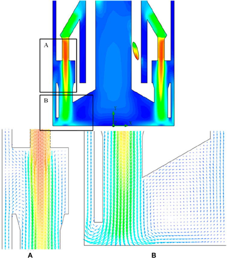
Figure 5. Typical velocity flow field in the drill bit. (A) Enlarged flow field view of annulus space, flushing nozzle section and mixing nozzle section. (B) Enlarged flow field view of annulus space, mixing nozzle section and expansion pressure section.
Figure 6 illustrates the impact of the suction nozzle layers on the dust control capacity of the drill bit. It demonstrates that augmenting the suction nozzle layers can enhance the dust control performance of the RC drill bit. The cross-sectional area of the flow experiences a significant rise with each added suction nozzle layer, consequently amplifying the airflow from the suction nozzles while maintaining a constant input air volume. This augmentation proves advantageous in enlarging the pressure difference within the central passage, thereby bolstering its suction capacity. However, the increased airflow unavoidably leads to a reduction in airflow from the flushing nozzles, thereby diminishing the energy consumption resulting from the airflow collision at the borehole bottom. Within the range of input air volume flow rates from 1 to 9 m3/min, there exists a critical input air volume flow rate. Initially, the sucked air flow rate increases with the rise in the input air volume flow rate. However, after the input air volume flow rate surpasses 3.8 m3/min, there is a notable decline in the sucked air volume flow rate despite further increases in the input air volume flow rate.
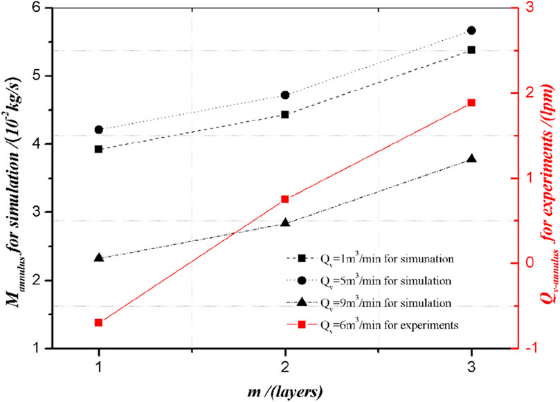
Figure 6. Influence of m on the dust control capacity.
A quadratic relationship is exhibited between the suction nozzle diameter and the suction of air flow rate, as shown in Figure 7. The suction of air flow rate reaches its maximum value when the suction nozzle diameter ranges from 5 to 5.5 mm. As for the effects of the suction nozzle layers, changing the suction nozzle diameter can change the allocation proportion of air flow rate from the suction and flushing nozzles. Enlarging the suction nozzle diameter before its critical value can maintain the air flow jet velocity while increasing the air flow rate, thus causing the improvement in the suction airflow. However, the airflow jet velocity would decrease remarkably when the suction nozzle diameter was greater than the critical value. Therefore, there is an optimal total flow sectional area for the suction nozzles. Both changing the suction nozzle layers and the diameter under the condition of keeping its optimal total flow sectional area can ensure the optimum dust control capacity.
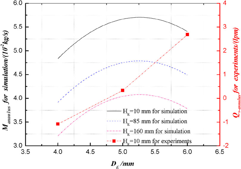
Figure 7. Influence of DE on the dust control capacity.
Figure 8 depicts a negative correlation between the suction nozzle location and the accommodated airflow rate. The positioning of the negative pressure zone generated by the suction nozzle is determined by its placement. As illustrated, a distant suction nozzle location detrimentally affects the dust control capacity of the drill bit because the negative pressure area fails to cover the borehole bottom adequately. Hence, it is preferable to position the suction nozzle in close proximity to the borehole bottom.
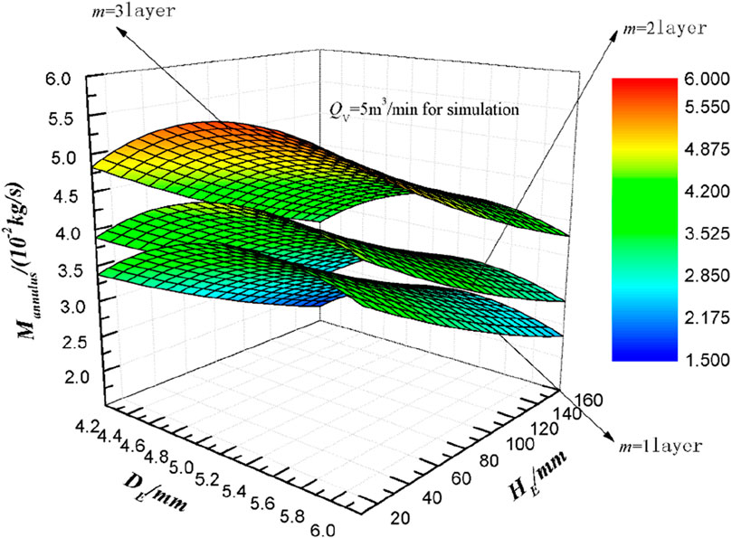
Figure 8. Synthetic influence of DE & HE on the dust control capacity.
The diameter of the flushing nozzle significantly impacts the dust control capacity of the RC drill bit. As depicted in Figure 9, the accommodated airflow rate noticeably decreases with the enlargement of the flushing nozzle diameter, all while maintaining a constant input air volume flow rate. As mentioned earlier, the input airflow can exit the drill tool through two passages: the suction nozzles and the flushing nozzles. When other parameters remain constant, increasing the flushing nozzle diameter indirectly reduces the suction nozzle size. As illustrated in Figure 5, airflow from the flushing nozzles can either enter the annulus between the drill tools and the borehole wall or flow into the center passage. The heightened airflow from the flushing nozzles due to diameter enlargement increases the airflow escaping into the annulus between the drill tools and the borehole wall, consequently resulting in poorer dust control performance.
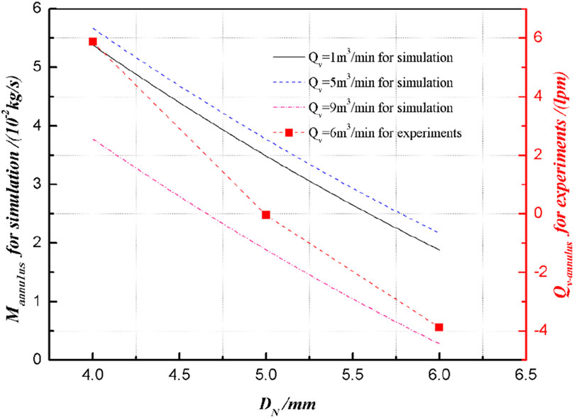
Figure 9. Influence of DN on the dust control capacity.
The input air volume flow rate also significantly influences the dust control capacity of the drill bit when the flushing nozzle diameter is fixed. Initially, the accommodated airflow increases with the rise in the input airflow volume, but it subsequently decreases as the input airflow volume continues to increase. This suggests the presence of a critical input air volume flow rate for the given drill bit parameters.
The distance between the flushing and mixing nozzles must not be too small; a distance of 20 mm appears to be optimal for LNT, as indicated in Figure 10. A smaller distance would constrain its air-suction capability. Maintaining the flushing nozzles with a robust air-suction capacity allows them to capture a portion of the escaping airflow. As previously discussed, when the RC drill bit lacks flushing nozzles, all input airflow can only exit the drill tools via the suction nozzles, indirectly improving the airflow rate from the suction nozzles. However, efficiently carrying out drill cuttings becomes challenging without the assistance of flushing nozzles to clear them away. Additionally, the drill bit’s teeth require cooling during the drilling process, making the flushing nozzles an essential component of the drill bit.
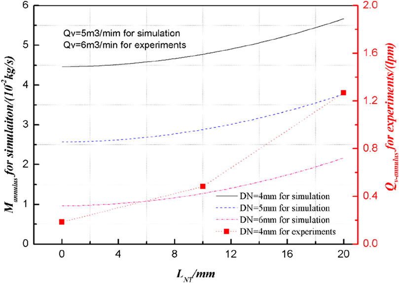
Figure 10. Influence of LNT on the dust control capacity.
Figure 11 illustrates the impact of the mixing nozzle diameter on the dust control performance of the drill bit. It indicates that enlarging the mixing nozzle diameter is advantageous for enhancing its dust control capacity. As the airflow exits the flushing nozzle, it draws air from the annulus region into the mixing nozzle. Mixing nozzles with a larger diameter guarantee adequate energy and mass exchange between the air jet and the drawn airflow. Furthermore, a larger diameter decreases the flow velocity of the mixing flows, consequently reducing the escaped airflow.

Figure 11. Influence of DT & LS on the dust control capacity.
Flow resistance plays a pivotal role in determining the airflow direction, and increasing the flow resistance proves to be an effective method for preventing airflow escape into the annulus between the drill tools and the borehole wall. Consequently, restricting the LS with a drill bit featuring smaller blades can enhance the dust control performance of the RC drill bit, as depicted in Figure 11.
According to the results of the range analysis, LD has little influence on the dust control performance of the RC drill bit, with LD = 15 mm being optimal for the current drill bit structure. Although θD has minimal effect on its dust control performance, there is a discernible trend for θD, demonstrating a parabolic relationship, as shown in Figure 12. A very small θD results in a right-angle turn at the inlet of the mixing nozzle, leading to significant local loss. Conversely, a very large θD induces a sudden turn, creating a whirlpool effect and increasing energy consumption.
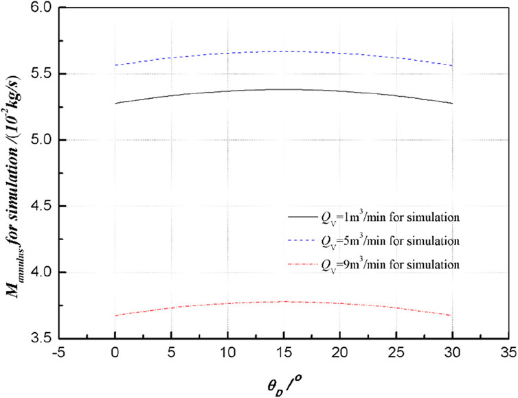
Figure 12. Influence of θD on the dust control capacity.
The RC drill bit (150 mm in diameter) with optimized parameters and its matched DTH air hammer GQ-142 were manufactured. They were employed to detect multilayer cavities with the assistance of a cavity auto-scanning laser system in Yuan Jiacun iron ore, which is affiliated with the Taiyuan Iron and Steel (Group) CO., LTD., and is located in Lanxian county of Shanxi province in the northwest of China. Figure 13 illustrates the schematic representation of this technique. During the drilling process, the system operates normally until the drill bit penetrates the roof of the cavity. At this point, the air hammer and the drill bit descend a segment due to gravity, limited by semi-circle clips, and the RC-DTH air hammer ceases operation immediately due to a valve mechanism failure. In the detection process, the lower drill pipes are secured on the drill deck to prevent the drill tools from falling into the cavity. Initially, the upper drill pipe above the ground is removed; then, the detection system is inserted into the cavity through the center passage of the drilling tool to obtain dimension information of the cavity. Finally, after completing the detection, the detection system is removed, and additional joints are added to continue the drilling process to detect the cavity below the upper one. The through-hole of the drill bit measures 55 mm, allowing the scanning unit with a diameter of 50 mm to cross it. Figure 14 depicts the field test drilling site employing the RC-DTH air hammer drilling method for detecting the goaf cavity. Compared with the conventional DTH air hammer employed nearby the test drilling site, the drill dust emission has been completely controlled. The field test verified that the modified drill bit effectively reduces dust emission.
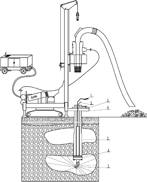
Figure 13. Schematic representation of the scanning process. 1: guide rod; 2: cable; 3: fork; 4: drill deck; 5: RC-DTH air hammer; 6: drill bit; 7: scanning unit.
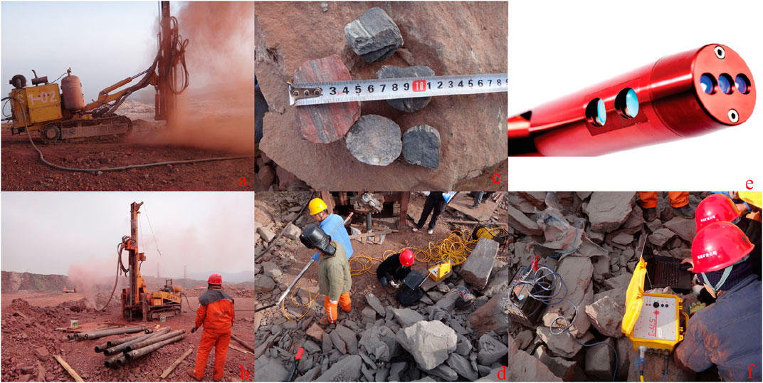
Figure 14. Field test of the RC-DTH air hammer. (A) Dusty drilling site with the conventional DTH air hammer drilling method. (B) Clean drilling site with the RC-DTH air hammer drilling method. (C) Discharged drill cuttings. (D) Preparation to place the scanning unit into the cavity through the center passage of the drill tools. (E) Cavity auto-scanning laser unit. (F) Conducting the cavity scanning process.
The structure parameters of the RC-DTH air hammer drilling method were optimized using an orthogonal design via fluid computational and experimental methods to enhance its dust control performance. Although some disparities exist between the simulation and experimental results, the effective trends for all the parameters align consistently. The findings indicate that increasing the suction nozzle layers, enlarging both the suction and mixing nozzle diameters, and optimizing the input airflow within a certain range are conducive to improving the dust control performance of the RC drill bit. Conversely, enlarging the flushing nozzle diameter and adjusting the suction nozzle location negatively impact the dust control capacity. Based on the optimized parameters, a 150-mm outer diameter RC drill bit was manufactured along with matching drill tools, including the DTH air hammer GQ-142. The field test results demonstrate the excellent dust control performance of the optimized RC drill bit. The DTH air hammer plays a critical role in reverse circulation drilling, and the parameters discussed in this paper can be applied to boreholes of any size. Enhanced dust control capability reduces well leakage.
As wells delve deeper and the initial spud-in drilling diameters increase, conventional drilling methods face challenges in circulating cuttings out of the wellbore, particularly in cases of circulation loss. Although conventional gas drilling can address circulation loss, it often requires substantial quantities of compressed air, numerous air supply units, occupies significant drilling site space, and incurs high costs, especially in large-diameter well drilling. These drawbacks limit the effectiveness of conventional gas drilling. However, dual-wall reverse circulation (RC) gas drilling technology has proven effective in addressing these challenges. This technology has shown no wellbore erosion due to high-speed returned air, minimal damage to low-pressure and permeability reservoirs, suitability for formation water applications, lower air consumption, and reduced drilling costs. It is widely utilized in geological prospecting, foundation engineering, hydrological well drilling, and other fields. Although RC gas drilling technology is relatively new in oil and gas exploration, it offers long-term benefits in cost-saving, efficiency improvement, energy conservation, and environmental protection. It holds promise for successful application in shallow gas, shale gas, coalbed methane (CBM), and other unconventional oil and gas reservoir exploration in the future.
The original contributions presented in the study are included in the article/supplementary material; further inquiries can be directed to the corresponding authors.
LF: investigation, methodology, and writing–original draft. ZL: methodology, project administration, and writing–review and editing. YL: resources, supervision, and writing–review and editing.
The author(s) declare that financial support was received for the research, authorship, and/or publication of this article. This study received financial support from the Scientific Research and Technological Development Project of China Petroleum Group Oilfield Technology Services Co., Ltd., under the title “Development and Application of Supporting Tools for Deep and Ultra-Deep Drilling, Completion, and Testing in Ten Thousand Meters” (No. 2024T-001-002).
The authors extend sincere appreciation for the valuable suggestions provided by the editor and reviewers.
Author LF and ZL were employed by PetroChina.
The remaining author declares that the research was conducted in the absence of any commercial or financial relationships that could be construed as a potential conflict of interest.
The authors declare that this study received funding from China Petroleum Group Oilfield Technology Services Co. Ltd. The funder had the following involvement in the study: data collection and analysis, decision to publish.
All claims expressed in this article are solely those of the authors and do not necessarily represent those of their affiliated organizations, or those of the publisher, the editors, and the reviewers. Any product that may be evaluated in this article, or claim that may be made by its manufacturer, is not guaranteed or endorsed by the publisher.
Cecala, A. B., O’Brien, A. D., Schall, J., Colinet, J. F., Franta, R. J., Schultz, M. J., et al. (2012) Dust control handbook for industrial minerals mining and processing. United States: National Institute for Occupational Safety & Health. Report of Investigations 9689.
Cecala, A. B., Organiscak, J. A., Zimmer, J. A., Heitbrink, W. A., Moyer, E. S., Schmitz, M., et al. (2003). Reducing enclosed cab drill operator’s respirable dust explosure at surface coal operation with a retrofitted filtration and pressurization system. Sme Trans. 314, 31–36.
Cooper, M. R., Susi, P., and Rempel, D. (2012). Case study: evaluation and control of respirable silica exposure during lateral drilling of concrete. J. Occup. Environ. Hyg. 9 (2), D35–D41. doi:10.1080/15459624.2011.640303
Deng, H., Fan, L., and Xu, Q. (2024). Development and prospects of multi-type reverse circulation drilling technology. J. Drill. Prod. Technol. 47 (1), 60–72. doi:10.3969/J.ISSN.1006-768X.2024.01.08
Han, G., Bruno, M., and Dusseault, M. (2005) Dynamically modelling rock failure in percussion drilling. The 40th U.S. Symposium on rock mechanics (USRMS): rock mechanics for energy, mineral and infrastructure. Anchorage, Alaska: Development in the Northern Regions. ARMA/USRMS 05-819.
Li, M., Luo, Y., and Jiang, H. (2016). Effects of proper drilling control to reduce respirable dust during roof bolting operations. Int. J. Coal Sci. Technol. 3 (4), 370–378. doi:10.1007/s40789-016-0154-x
Liu, J., and Yin, K. (2012). Development of SGQ-320 type reverse circulation DTH hammer used in gas drilling. Pet. Drill. Tech. 40 (1), 114–118. doi:10.3969/j.issn.1001-0890.2012.01.023
Lyons, W. C., Guo, B., and Hawley, G. D. (2009) Air and gas drilling manual. Third Edition. USA: Elsevier.
Maksimovic, S. D., and Page, S. J. (1985) Quartz dust sources during overburden drilling at surface coal mines. Information Circular/1985. Pittsburgh, PA (USA): Bureau of Mines. PB-86-169141/XA Pittsburgh Research Center.
Mixon, B., and Nain, J. (2013). Complying with occupational safety and health administration regulations: a guide for compounding pharmacists. Int. J. Pharm. Compd. 17 (3), 182–190.
Organiscak, J. A., and Page, S. J. (1995) Assessment of airborne dust generated from small truck-mounted rock drills. Pittsburgh Pa: U.s.department of the Interior Bureau of Mines Ri. Report of Investigations 9616.
Page, S. J. (1991). Respirable dust control on overburden drills at surface mines. Proc. 1991 Am. Min. Congr. Coal Convention 4, 523–539.
Sundae, L. S. (1995) The reduction of airborne dust generated by roof bolt drill bits through the use of water. United States: United States Department of the Interior. Report of Investigations 9594.
Tavakol, E., Azari, M., Zendehdel, R., Salehpour, S., Khodakrim, S., Nikoo, S., et al. (2016). Risk evaluation of construction workers’ exposure to respirable crystalline silica and respirable dust. J. Saf. Promot Inj. Prev. 3 (4), 263–270.
USBM (1987) Optimizing dust control on surface coal mine drills. United States: By Page SJ. U.S. Department of the Interior. Bureau of Mines Technology News 286.
Zhang, D., Zhu, T., Lv, Y., Hou, J., and He, Y. (2017) Research on fault diagnosis for air drilling based on an improved PSO for optimization of fuzzy neural network. Singapore: Springer Singapore.
Zimmer, R., Lueck, S., and Page, S. (1987). Optimization of overburden drill dust control systems on surface coal mines. Int. J. Surf. Min. Reclam. Environ. 1 (2), 155–157. doi:10.1080/09208118708944113
Keywords: orthogonal design, reverse circulation, DTH air hammer, drill bit, dust control, unconventional oil and gas reservoir
Citation: Fan L, Li Z and Luo Y (2024) Parametrical design and optimization of a reverse circulation drill bit for dust control. Front. Built Environ. 10:1395464. doi: 10.3389/fbuil.2024.1395464
Received: 04 March 2024; Accepted: 30 April 2024;
Published: 18 June 2024.
Edited by:
Peng Tan, CNPC Engineering Technology R & D Company Limited, ChinaReviewed by:
Chen Xiaobin, Central South University, ChinaCopyright © 2024 Fan, Li and Luo. This is an open-access article distributed under the terms of the Creative Commons Attribution License (CC BY). The use, distribution or reproduction in other forums is permitted, provided the original author(s) and the copyright owner(s) are credited and that the original publication in this journal is cited, in accordance with accepted academic practice. No use, distribution or reproduction is permitted which does not comply with these terms.
*Correspondence: Zhilin Li, bGl6bF9jY2RlQGNucGMuY29tLmNu
Disclaimer: All claims expressed in this article are solely those of the authors and do not necessarily represent those of their affiliated organizations, or those of the publisher, the editors and the reviewers. Any product that may be evaluated in this article or claim that may be made by its manufacturer is not guaranteed or endorsed by the publisher.
Research integrity at Frontiers
Learn more about the work of our research integrity team to safeguard the quality of each article we publish.