 Lemin Ma1
 Wei Guo
95% of researchers rate our articles as excellent or good
Learn more about the work of our research integrity team to safeguard the quality of each article we publish.
Find out more
ORIGINAL RESEARCH article
Front. Built Environ. , 19 July 2024
Sec. Geotechnical Engineering
Volume 10 - 2024 | https://doi.org/10.3389/fbuil.2024.1330580
A series of in situ tests were conducted using the low-strain integrity testing method to detect the defects of cast-in-place concrete piles. Numerical studies were conducted to observe the time-domain waveform along cast-in-place concrete piles with diameter expansion, diameter reduction and segregation defects. It is found the time-domain waveforms of the pile with the diameter expansion defects have second wave troughs after the first wavelength while those with diameter reduction and segregation defects have second wave crests. However, it is difficult to use amplitudes to directly determine the length, diameter and segregation degree of the defects. The second wavelengths could be used to identify the lengths of diameter reduction and segregation defects but it is hard to identify those of diameter expansion defects. The locations of diameter reduction and segregation defects could be determined through the time of second wave crests using the linear interpolation method, and those of diameter expansion defects could be determined through the time of second wave trough.
The cast-in-place piles are extensively used as the foundation for high-rise buildings due to their high bearing capacity, wide applicable geological conditions, strong deformation resistance, and low vibration and noise levels during pile installation (Loseva et al., 2022; Prakashvel et al., 2022; Jian et al., 2023). The defects in the pile body, i.e., diameter expansion and reduction, toe debris, mud cake and pile broken, may heavily influence its integrity, and bearing capacity (Poulos, 2005). The in situ non-destructive quality inspection methods are often used to identify the potential defects in the pile body because they cannot be identified visually as superstructures. The commonly used methods include the low-strain sonic integrity testing method (Lozovsky et al., 2020), the cross-hole sonic testing method (Sheinin et al., 2016), and the core drilling method (Morgano, 1996).
The low-strain sonic integrity testing method is one of the most commonly used pile integrity testing methods because it is simple, inexpensive, and fast to perform requiring very little preparation on the pile head (Likins and Rausche, 2000; Massoudi and Teffera, 2004; Ni et al., 2006). The test uses a small hand-held hammer, typically 4 to 5 cm in diameter, to impact the pile head and an accelerometer placed on the pile head to capture the acceleration time history. The captured velocity-time curves are usually interpreted based on the 1D stress wave theory by assuming a uniform load on the pile head (Ni et al., 2008; Wang et al., 2010). The anomalies of the pile body can be located and characterized by the arrival time and waveforms of the reflections (Chai et al., 2011).
The investigation on the feasibility of using sonic integrity testing to detect concrete fractures was started in the 1970s (Steinbach and Vey, 1975). Ni and Huang. (2013) examined the integrity of large-diameter cast-in-place concrete piles using contact surface reflected waves. Kachanov et al. (2017) investigated the limitations of detecting the integrity of concrete piles with near-surface defects by the reflected wave method and used the impact echo method to determine the location of defects in the piles. Genadii and Iurii. (2016) concluded that some serious problems may be raised with the diagnosis of much larger defects because of the concrete heterogeneity, irregularity of concrete physical and mechanical properties, variations of cross-section shape, and soil conditions along the pile length.
The commonly used parameters in characterizing pile defects are the propagation velocity of waves and the reflected wave crests. The interpretation of low-strain sonic integrity testing results based on the 1D stress wave theory may no longer be accurate in complex geological conditions (Chow et al., 2003). This is because the stress wave reflection methods rely on a single waveform is challenging to accurately determine the parameters for different types of piles (Niederleithinger and Taffe, 2006; Ni et al., 2012). The 3D effects in the form of surface waves made the interpretation more complicated which was often analyzed using the 3D finite element method (Lu et al., 2013; Lozovsky et al., 2020). To simulate the low-strain sonic integrity testing method, the pile and soil are simulated using a viscoelastic model (Chow et al., 2003; Chai et al., 2010; Zheng et al., 2016; Zheng et al., 2018; Liu et al., 2020). To reflect the velocity vibration response at the pile head, the elimination of the effect of Rayleigh waves has to be conducted (Seidel and Tan, 2004a; Seidel and Tan, 2004b).
In this paper, a series of in situ tests were conducted using the low-strain integrity testing method to detect the defects of cast-in-place concrete piles. Numerical studies were conducted to observe the time-domain waveform of cast-in-place concrete piles with diameter expansion, diameter reduction and segregation defects. The factors affecting the accuracy to evaluate the pile defects are investigated which could give certain guidelines for the engineers to analyze the waveforms to ensure the safety and reliability of the pile project.
The expansion of the Tianjin Binhai International Airport included the construction of a new runway and terminal at the Binhai New District, Tianjin, China. The terminal was designed to use cast-in-place bored piles and raft foundations to support the building. Each cast-in-place bored pile has an outer diameter of 0.8 m and a depth of nonuniformly distributed ranging from 30 to 40 m over the site. The concrete grade used to concrete the cast-in-place bored pile is C35 with a concrete protective layer of 5 cm. The soil types in the site were generally consistent and roughly divided into four layers. The first layer is a plain fill layer with a thickness of 2 m, a cohesion of 24.5 kPa, and an internal friction angle of 20°. The second layer is a clay layer with a thickness of 4 m, an average moisture content of 41.9%, a cohesion of 14.5 kPa, and an internal friction angle of 23.4°. The third layer is a silty clay layer with a thickness of 30 m, a cohesion of 23.4 kPa, and an internal friction angle of 21°. The fourth layer is a sand layer which is a hard holding layer with a thickness of 14 m, and internal friction angle of 33°. More details of the soil properties on the site are tabulated in Table 1.
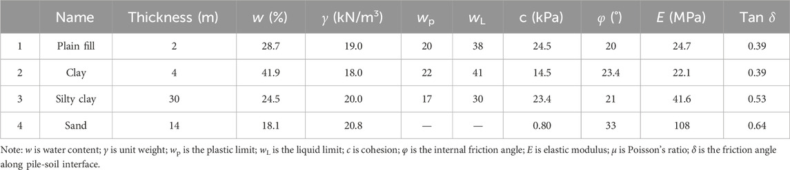
Table 1. Soil properties.
After the installation of the cast-in-place bored piles, the low-strain integrity testing was conducted according to JGJ 106–2014 (2014). The tested five piles are numbered S7, S8, S10, S12, and S15. The main testing equipment includes a foundation pile dynamometer (model FEI-C3), an acceleration sensor, and a hammer with weight of 13 kg. The striking position of the hammer is at the center of the pile. The acceleration sensor receives the signal at a two-thirds radius from the center of the pile.
The time-domain waveform was obtained by integrating the acceleration signal as shown in Figure 1. It can be found that there is no reflected wave crest at the time-domain curves of piles No. S7, S10, S12, and S15. The small wave troughs of the reflected waves at the time of around 10 ms are due to the small expansion of the pile diameters. The reflected wave of S8 pile has a wave crest at the time of 8.6 ms as shown in Figure 1B. This was due to the pile necking defect. According to the two wave crests located at the pile head and pile end, using the linear interpolation method gives the location of the necking defect at 9 m below the ground surface. The pile was excavated and found that the pile necking occurred with a necking diameter of approximately 0.7 m at the pile body ranging from 8 to 10 m from the pile head which proved the accuracy of the low-strain test results. It is also found that the wave velocities of the intact piles range from 3,800 m/s to 3,890 m/s, while that of pile No. S8 is litter lower with its magnitude of 3,750 m/s. More details of the results from the low-strain tests are summarized in Table 2.
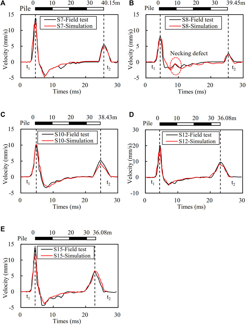
Figure 1. Comparison of the time-domain waveforms from in situ field tests and numerical simulation (A) S7, (B) S8, (C) S10, (D) S12, (E) S15.
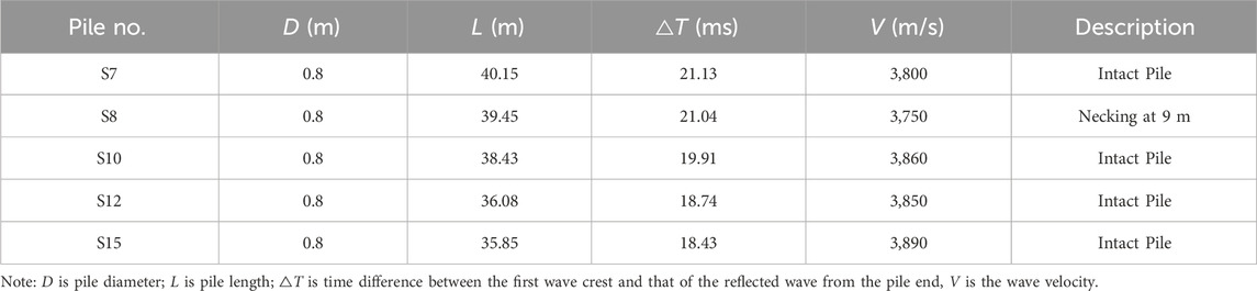
Table 2. The results of the low-strain integrity testing.
Numerical studies were conducted to observe the time-domain waveform in the cast-in-place concrete piles with diameter expansion, diameter reduction and segregation defects. The in situ low-strain integrity tests were simulated to verify the accuracy of the proposed numerical model. The pile and soil are modeled as linear-elastic materials using C3D8 solid elements as shown in Figure 2. The soil is in a cylinder shape with a depth of 60 m and a diameter of 8 m which is 10 times the diameter of the pile. The properties of the soil are the same as those shown in Table 1. The piles were modeled with their diameters of D = 0.8 m and variable lengths as shown in Table 2. The pile number S8 has a necking defect ranging from 8 to 10 m from the pile head with a necking diameter of 0.7 m according to the field observation. The concrete, main bars, spiral bars, and reinforcing bars in cast-in-place bored piles were simulated separately. The Young’s modulus and axial compressive strength of the concrete material are 31.5 GPa and 35 MPa, respectively. The main bars consist of 10 steel bars with a diameter of 20 mm, and strength of HRB400 grade. The spiral bars are 8 mm in diameter and HRB300 in strength grade. The spacing of the spiral bars is 0.1 m within 10 m of the pile depth and 0.2 m below 10 m of the pile depth. The reinforcing bars are selected with a diameter of 18 mm and a strength of HRB400 grade and are installed at an interval of 2 m. The main bars, spiral bars, and reinforcing bars are embedded in concrete during modeling as shown in Figure 2B. More details of cast-in-place concrete pile properties used in the numerical model are summarized in Table 3. The relationship between the friction angle along pile-soil interface δ was proposed by Kulhawy (1984) with their expression of δ = (0.8–1.0)φ for smooth concrete piles where φ is the internal friction angle of soil. In the current study, the skin resistance along the pile-soil interface is Coulomb friction with friction coefficient tan δ = tan φ. The calculated friction coefficient tan δ of each soil layer is shown in Table 1. As the purpose of the current study is to simulate the time-domain waveform in the cast-in-place concrete piles, the average values of tan δ of the four soil layers with its magnitude of 0.45 are used to simulate all the pile-soil interfaces. The reflection-free boundaries are set at the edge and bottom of the soil layer to avoid additional reflected waves.
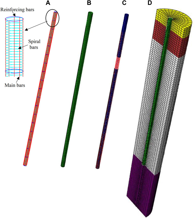
Figure 2. Mesh of the pile and soil models (A) Reinforcing steel cage, (B) intact pile, (C) Defective pile, (D) Pile-soil modeling.
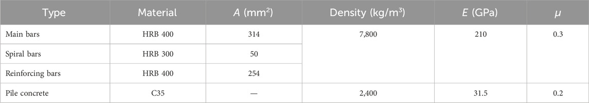
Table 3. Properties of cast-in-place concrete pile used in the numerical model.
The low-strain test is simulated by applying a hammer falling freely from a certain height above the pile head to generate transient loads. The reflected wave is received at a point of 2/3 radius from the pile center. The longitudinal transient excitation force p(t) at the top of the pile is simulated using the following sinusoidal impulse equation (Seidel and Tan, 2004a; Loseva et al., 2022).
where F is the maximum transient excitation force and F = 10 kN, t is the time, ft is the duration of the excitation force with a value of 0.001 s.
The simulated time-domain waveforms are compared with those from the in situ low-strain tests as shown in Figure 1. It can be seen that the time-domain signals obtained from the two methods are in fair agreement which verified the accuracy of the numerical model. For the results of pile No. S8, the time-domain signals obtained from numerical simulation also show an obvious wave crest at the time of 9 ms as shown in Figure 1B.
The parameter studies are conducted to investigate the effects of diameter expansion, diameter reduction, and segregation on the reflected time-domain waveforms. The soil layers and the cast-in-place pile are modeled the same as those discussed in Chapter 3 except the length of the pile is fixed as 36 m. The length, diameter, and location of the pile defects are taken as variables in the parametric studies.
The defect of diameter expansion refers to the phenomenon that some sections of the pile appear significantly larger than the designed pile diameter after pile installation. The main reason for this phenomenon is due to the collapse of the disturbed soil around the predrilled hole which cannot resist the vibration impact in the process of concrete filling. The defect of diameter expansion may induce uneven settlement of the foundation. A series of numerical studies are conducted to investigate the influence of length, diameter, and location of diameter expansion defect on the reflection waveform.
The pile is modeled with an expansion diameter of 1.1 m, an intact diameter D = 0.8 m, and different expansion lengths ranging from 1.2 m (s = 1.5D) to 4.8 m (s = 6D) as shown in Figure 3A. The surface of the diameter expansion defect is located 15 m from the pile head. The waveforms of the cast-in-place piles with different lengths of diameter expansions are shown in Figure 3B. For comparison purposes, a velocity curve of an intact pile is also plotted in the figure. It can be found that obvious reflection signals are generated at the location of the pile defects. The reflected waveforms have second wave troughs at a time of 12.5 ms and wave crests at a time after 14.6 ms. The wavelengths correspond to the ranges of the diameter expansion defects. The more the lengths of the diameter expansion the higher magnitudes of the wavelengths and amplitudes. For example, the time differences of the wavelength are 1.88 ms and 2.59 ms for the cast-in-place bored pile with the lengths of the diameter expansion of 1.2 m and 4.8 m, respectively. It was also found the time to reach the pile ends remained unchanged. However, the more the lengths of the diameter expansion the higher amplitudes of the wave crests at the pile ends. This is because the longer diameter expansion lost more wave energy into the surrounding soil layers.
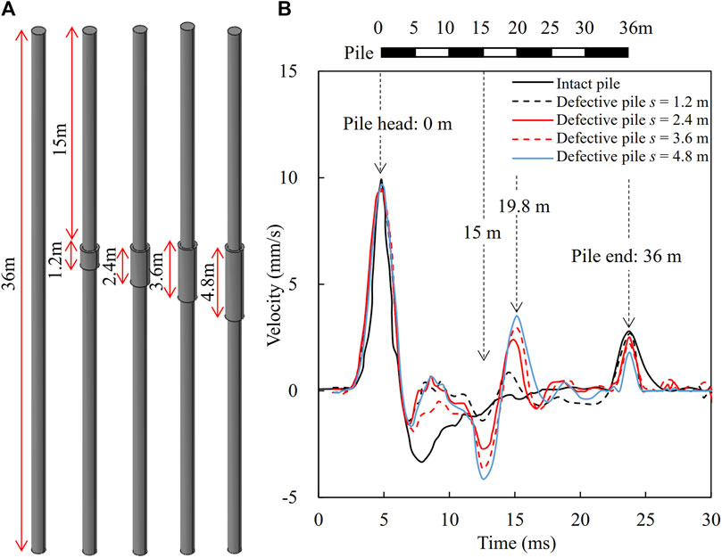
Figure 3. Effect of expansion length on the time-domain waveform (A) pile models, and (B) time-domain waveforms.
To investigate the influence of the expansion diameter on the time-domain waveform, the expansion diameters (d) are taken as variables with their magnitudes ranging from d = 1.0 m to d = 1.3 m as shown in Figure 4A. The cast-in-place piles are modeled with diameter expansion defects located at 15 m from the pile head and an expansion length of 3 m. The waveforms of the cast-in-place piles with different expansion diameters are shown in Figure 4B. It can be found that the reflected time domain waveforms are similar to Figure 3B except for higher amplitudes of the wave crests. The wavelengths are also increased with the increase of expanding diameters. It is also found the time of wave crests at the pile ends delays with the increase of the expanding diameters because more wave energies transfer into surrounding soil layers.
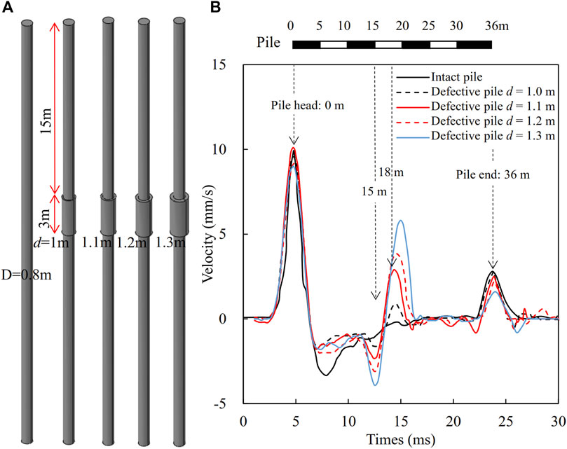
Figure 4. Effect of expanding diameter on time domain signal (A) pile models, and (B) time-domain waveforms.
To investigate the influence of the locations of diameter expansion on the time-domain waveform, the piles are modeled with an expansion length of 3 m, an expansion diameter of d = 1.3 m, and an expansion location from the pile head ranging from h = 5 m to h = 30 m as shown in Figure 5A. The obtained time-domain waveforms along the cast-in-place piles with different expansion locations are shown in Figure 5B. It can be seen that the expansion locations could be identified through the time of the second wave troughs. Furthermore, the deeper the expanding location the lower the amplitudes of the wave troughs of the reflected waves. The location of the diameter expansion in the pile also influences amplitudes of the wave crests at the pile end, but influences a little on its arrival time.
Figure 5. Effect of expanding location on time domain signal (A) pile models, and (B) time-domain waveforms.
The defect of diameter reduction or pile necking refers to the reduction of pile diameter at a certain place after pile installation. The necking may be induced either by the collapsed surrounding soil and misshape of the movable concrete mixture or by the disruption of the concreting operation. Parametric studies are conducted to investigate the influence of the length, diameter and location of the diameter reduction defects of the cast-in-place piles on the time-domain waveforms.
The piles are modeled with diameter reduction defects with a diameter of 0.5 m located at 10 m from the pile head. The lengths of diameter reduction (l) are taken as variables with their magnitudes ranging from 2 m to 5 m as shown in Figure 6A. The time-domain waveforms of the cast-in-place piles with different lengths of the diameter reduction defects are shown in Figure 6B. It can be found that the second wavelength corresponds to the length of diameter reduction. For example, the waveform of the pile with lengths of the diameter reduction defects of 2 m and 5 m have second wavelengths of 1.4 ms and 2.5 ms, respectively. The diameter reduction defects make the time-domain waveform have higher amplitudes of the second wave crests at the time-domain of approximately 10.5 ms.
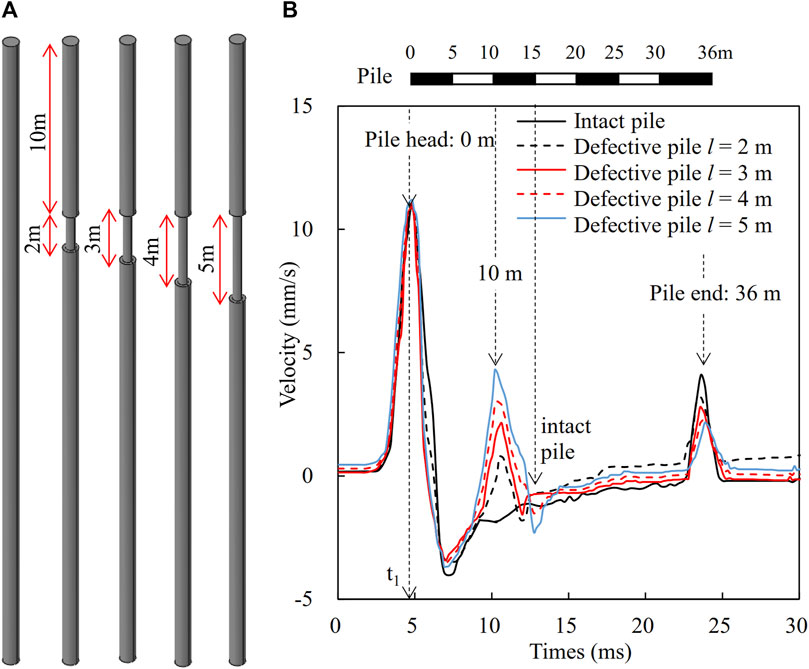
Figure 6. Effect of necking length on time domain signal (A) pile models, and (B) time-domain waveforms.
To investigate the influences of the necking diameter on the time-domain waveform, the piles are modeled with the necking length of 3 m located at 10 m from the pile head and necking diameter (d) ranging from d = 0.6 m to d = 0.3 m as shown in Figure 7A. The time-domain waveforms of the cast-in-place piles with different necking diameters are shown in Figure 7B. Generally, the second wavelengths remain the same as the lengths of diameter reduction remain constant. The amplitudes of the second wave crests increase with the decrease of the necking diameter.
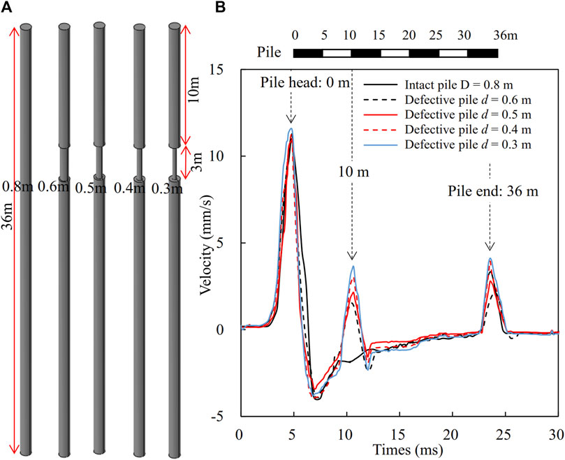
Figure 7. Effect of necking diameter on time domain signal (A) pile models, and (B) time-domain waveforms.
To investigate the influence of the locations of the diameter reduction, the piles are modeled with the necking length of 3 m and necking diameter (d) of d = 0.5 m, and different necking locations ranging from 5 m to 30 m from pile head as shown in Figure 8A. The time-domain waveforms along the cast-in-place piles with different necking locations are shown in Figure 8B. It can be found that the time of the second wave crests could be used to identify the location of the diameter reduction defects. The amplitudes of the second wave crests decrease with the depth of the diameter reduction defects. The time to reach the pile end remained unchanged but the amplitudes of the wave crest gradually decrease.
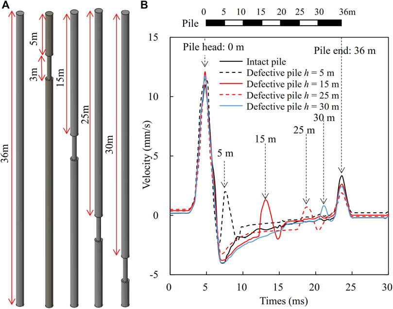
Figure 8. Effect of necking location on time domain signal (A) pile models, and (B) time-domain waveforms.
The segregation defect refers to the defective cast-in-place concrete pile due to the use of substandard pile materials, improper batching ratios, uneven mixing or inadequate vibration, and high sand content in some areas of the pile body. The segregation defect heavily affects the strength and bearing capacity of the cast-in-place concrete pile foundations. The segregation defects are usually simulated by reducing the elastic modulus and density of the intact piles (Loseva et al., 2022). Parametric studies are conducted to investigate the influence of the length, segregation degree, and location of the segregation defects on the time-domain waveforms along the cast-in-place piles.
To investigate the influence of the segregation length on the time-domain waveforms, the piles are modeled with the segregation location of 10 m from the pile head and the segregation length (l) ranging from 2 m to 5 m as shown in Figure 9A. The elastic modulus and density of the segregated section are taken as 0.6 and 0.8 times those of the intact pile, respectively. The time-domain waveforms of the cast-in-place piles with different segregation lengths are shown in Figure 9B. It can be found that the segregation locations could be identified by the time of second wave crests. The second wavelength could reflect the segregation lengths. The amplitudes of the wave crests increase with the increase of the segregation length. This phenomenon is similar to those of piles with diameter reduction defects as shown in Figure 6B.
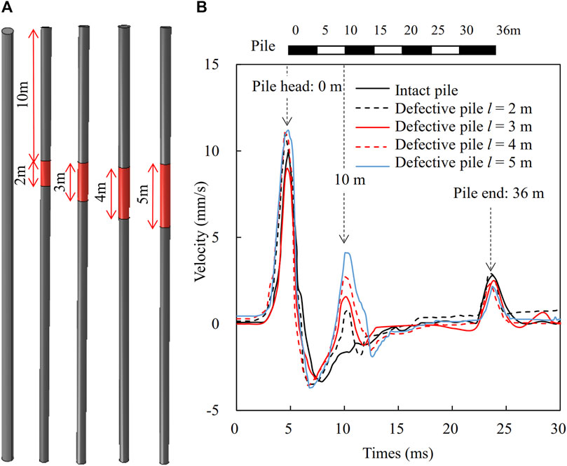
Figure 9. Effect of segregation length on time domain signal (A) pile models, and (B) time-domain waveforms.
To investigate the influence of the segregation degree on the time-domain waveforms, the piles are modeled with a segregation length of 3 m, a location of 10 m from the pile head and different elastic moduli ranging from 0.6E to 0.9E, where E is the elastic modulus of the intact pile, as shown in Figure 10A. The time-domain waveforms along the cast-in-place piles with different degrees of segregation are shown in Figure 10B. It can be found the lower the degree of segregation, the larger the amplitudes of the second wave crests. For example, the amplitudes are 4.54 mm/s and 1.06 mm/s for the defect piles with the elastic modulus of the segregated sections of 0.6E and 0.9E, respectively. It is also found the segregation section induces many wavelengths which are different from those obtained from piles with diameter expansion and diameter reduction defects.
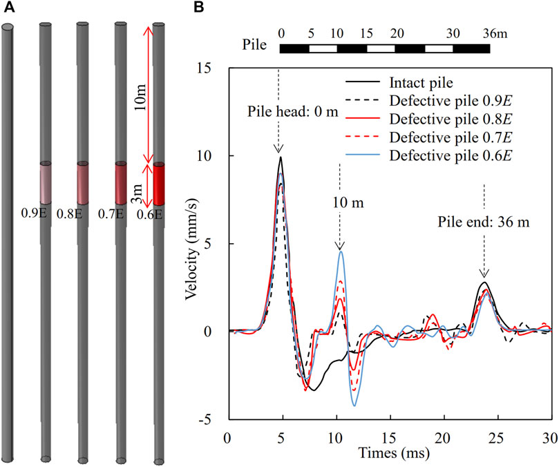
Figure 10. Effect of segregation degree on time domain signal (A) pile models, and (B) time-domain waveforms.
To investigate the influence of the segregation locations on the time-domain waveforms, the piles are modeled with a diameter D = 0.8 m, a segregation length of 3 m, and a segregation location ranging from 5 m to 30 m from pile head as shown in Figure 11A. The elastic modulus and density of the segregated section are taken as 0.6 and 0.8 times those of the intact pile, respectively. The time-domain waveforms along the cast-in-place piles with different segregation locations are shown in Figure 11B. It can be found that the time of the second wave crest could be used to identify the position of the segregation. The second wavelength could be used to identify the lengths of pile segregation defects. The amplitudes of the second wave crests gradually decrease with the increase of the segregation location. However, the lengths of the segregation defects have little influence on the wave crests on pile ends.
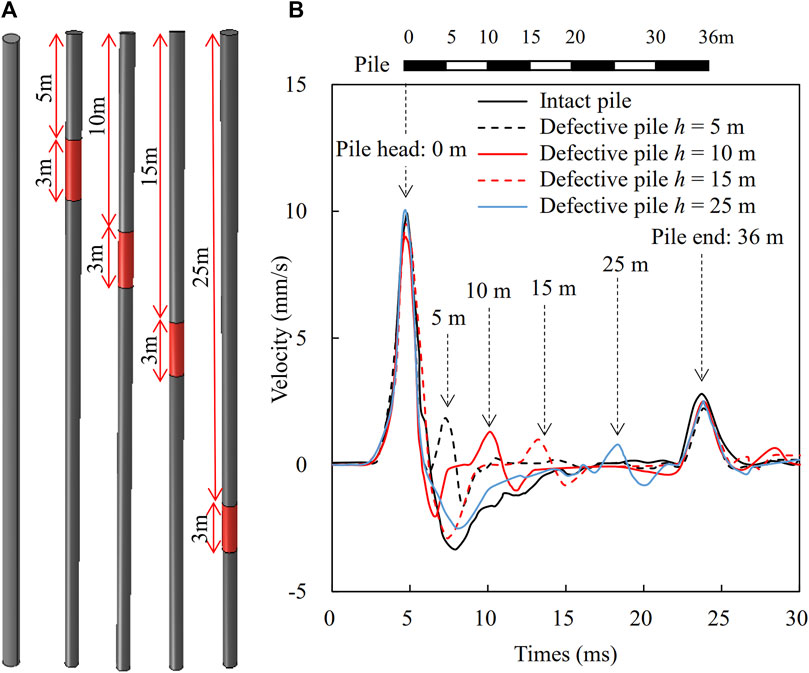
Figure 11. Effect of segregation location on time domain signal (A) pile models, and (B) time-domain waveforms.
In this paper, a series of numerical studies were conducted to observe the time-domain waveform of cast-in-place concrete piles with diameter expansion, diameter reduction, and segregation defects. In-situ tests were conducted using the low-strain integrity testing method to verify the accuracy of the proposed numerical model. The following conclusions can be drawn from this study:
(1) The waveforms of the cast-in-place piles with diameter expansions have a second wave trough than those of intact piles. The expansion locations could be identified through the time of the second wave trough using the linear interpolation method. The more the lengths and diameters of the diameter expansion defects the higher the magnitudes of the wavelengths and amplitudes.
(2) The diameter reduction defects make the time-domain waveform have second wave crests. The second wavelengths could be used to identify the lengths of diameter reduction. The time of the second wave crests could be used to identify the location of the diameter reduction defects.
(3) The segregation section induces many wavelengths which are different from those obtained from piles with diameter expansion and diameter reduction defects. The segregation locations could be identified by the time of second wave crests. The second wavelength could reflect the lengths of segregation defects.
(4) The amplitudes of the second wave trough for piles with diameter expansion defect and wave crests for piles with diameter reduction and segregation defect could be influenced by diameter, length and segregation degree of defects. It is difficult to use amplitudes to directly determine the length, diameter and segregation degree of the defects.
The original contributions presented in the study are included in the article/Supplementary Material, further inquiries can be directed to the corresponding author.
LM: Data curation, Formal Analysis, Writing–original draft. ZD: Conceptualization, Data curation, Writing–original draft. WG: Funding acquisition, Investigation, Methodology, Project administration, Supervision, Writing–review and editing. YR: Conceptualization, Data curation, Formal Analysis, Writing–original draft.
The author(s) declare that no financial support was received for the research, authorship, and/or publication of this article.
Authors LM and ZD were employed by Tianjin Survey Design Institute Group Co., Ltd.
The remaining authors declare that the research was conducted in the absence of any commercial or financial relationships that could be construed as a potential conflict of interest.
The author(s) declared that they were an editorial board member of Frontiers, at the time of submission. This had no impact on the peer review process and the final decision.
All claims expressed in this article are solely those of the authors and do not necessarily represent those of their affiliated organizations, or those of the publisher, the editors and the reviewers. Any product that may be evaluated in this article, or claim that may be made by its manufacturer, is not guaranteed or endorsed by the publisher.
Chai, H. Y., Phoon, K. K., and Zhang, D. J. (2010). Effects of the source on wave propagation in pile integrity testing. J. Geotech. Geoenviron. 136 (9), 1200–1208. doi:10.1061/(asce)gt.1943-5606.0000272
Chai, H. Y., Wei, C. F., Phoon, K. K., and Yang, Y. M. (2011). Some observations on the performance of the signal matching technique in assessment of pile integrity. J. Nondestruct. Eval. 30, 246–258. doi:10.1007/s10921-011-0113-9
Chow, Y. K., Phoon, K. K., Chow, W. F., and Wong, K. Y. (2003). Low strain integrity testing of piles: three-dimensional effects. J. Geotech. Geoenviron. 129 (11), 1057–1062. doi:10.1061/(asce)1090-0241(2003)129:11(1057)
Genadii, F., and Iurii, K. (2016). Experimental diagnostics theoretical diagnostics of defects in ferroconcrete piles based on reflection of longitudinal and transverse waves. Tech. Eng. Meet., 1307–1317. doi:10.1007/978-3-319-59471-2_151
JGJ 106-2014 (2014). Technical code for testing of building foundation piles. Beijing, China: China Architecture and Building Press.
Jian, Z. Y., Wang, Z. P., Feng, K., Zhang, Y., and Gorgin, R. (2023). Low-strain damage imaging detection experiment for model pile integrity based on HHT. Struct. Dura. Health. Monit. 17 (6), 557–569. doi:10.32604/sdhm.2023.042393
Kachanov, V. K., Sokolv, I. V., Fedorenko, S. A., and Lebedev, S. V. (2017). Use of the impact-echo method for analyzing the integrity of driven reinforced concrete piles. Meas. Tech. 60 (4), 386–391. doi:10.1007/s11018-017-1207-2
Kulhawy, F. H. (1984). “Limiting tip and side resistance: fact or fallacy, Analysis and design of pile foundations,” in Proceedings of a symposium in conjunction with the ASCE national convention (San Francisco, USA: ASCE), 80–98.
Likins, G. E., and Rausche, F. (2000). “Recent advances and proper use of PDI low strain pile integrity testing,” in Proc. 6th int. Conf. On the application of stress-wave theory to piles (USA: CRC Press), 211–218.
Liu, X., Hesham, E. N., Wang, K. H., and Wu, W. (2020). Theoretical analysis of three-dimensional effect in pile integrity test. Comput. Geotech. 127, 103765. doi:10.1016/j.compgeo.2020.103765
Loseva, E., Lozovsky, I., and Zhostkov, R. (2022). Identifying small defects in cast-in-place piles using low strain integrity testing. Indian. Geotech. J. 52 (2), 270–279. doi:10.1007/s40098-021-00583-y
Lozovsky, I. N., Zhostkov, R. A., and Churkin, A. A. (2020). Numerical simulation of ultrasonic pile integrity testing. Russ. J. Nondestruct. Test. 56, 1–11. doi:10.1134/s1061830920010064
Lu, Z., Wang, Z. L., and Liu, D. J. (2013). Study on low-strain integrity testing of pipe-pile using the elastodynamic finite integration technique. Int. J. Numer. Anal. Methods Geomech. 37 (5), 536–550. doi:10.1002/nag.2122
Massoudi, N., and Teffera, W. (2004). Non-destructive testing of piles using the low strain integrity method. Proc. 5th Int. Conf. Case Hist. Geotechnical Eng. Mo. Univ. Sci. Technol. Rolla, MO, 13–17.
Morgano, C. M. (1996). “Determining embedment depths of deep foundations using non-destructive methods,” in Proc. 5th int. Conf. On the application of stress-wave theory to piles (Orlando, FL: Univ. of Florida), 734–747.
Ni, S. H., Charng, J. J., and Lo, K. F. (2006). Low-strain integrity testing of drilled piles with high slenderness ratio. Comput. Geotech. 33 (6-7), 283–293. doi:10.1016/j.compgeo.2006.08.001
Ni, S. H., and Huang, Y. H. (2013). Integrity evaluation of PCC piles using the surface reflection method. Exp. Tech. 37, 63–73. doi:10.1111/j.1747-1567.2012.00832.x
Ni, S. H., Isenhower, W. M., and Huang, Y. (2012). Continuous wavelet transform technique for low-strain integrity testing of deep drilled shafts. J. GeoEng. 7 (3), 97–105. doi:10.6310/jog.2012.7(3).3
Ni, S. H., Lo, K. F., Lehmann, L., and Huang, Y. H. (2008). Time-frequency analyses of pile-integrity testing using wavelet transform. Comput. Geotech. 35 (4), 600–607. doi:10.1016/j.compgeo.2007.09.003
Niederleithinger, E., and Taffe, A. (2006). Early stage elastic wave velocity of concrete piles. Cem. Concr. Comp. 28 (4), 317–320. doi:10.1016/j.cemconcomp.2006.02.013
Poulos, H. G. (2005). Pile behavior—consequences of geological and construction imperfections. J. Geotech. Geoenviron. 131 (5), 538–563. doi:10.1061/(asce)1090-0241(2005)131:5(538)
Prakashvel, J., Harishkumaran, S., Vasudevan, P., and Sathishkumar, K. (2022). Application of wave propagation with low strain pile integrity test—a case study. Lect. Notes. Civ. Eng. 188, 381–386. doi:10.1007/978-981-16-5673-6_31
Seidel, J. P., and Tan, S. K. (2004a). “Elimination of the Rayleigh wave effect on low strain integrity test results. Part 1: experimental investigation,” in 7th international conference on the application of stress wave theory to piles (Institution of Engineers Malaysia: Petaling Jeya), 179–185.
Seidel, J. P., and Tan, S. K. (2004b). “Elimination of the Rayleigh wave effect on low strain integrity test results. Part 2: Rayleigh wave elimination technique,” in 7th international conference on the application of stress wave theory to piles (Malaysia: Institution of Engineers Malaysia, Petaling Jeya), 187–192.
Sheinin, V. I., Dzagov, A. M., Kostenko, E. S., Manzhin, A. P., Lokhin, D. I., Maksimovich, I. B., et al. (2016). Determining the strength characteristics of concrete in drilled piles from tests on extracted core specimens. Soil. Mech. Found. Eng. 53 (2), 119–124. doi:10.1007/s11204-016-9374-8
Steinbach, J., and Vey, E. (1975). Caisson evaluation by stress wave: propagation method. J. Geotech. Eng. Div. 101 (4), 361–378. doi:10.1061/ajgeb6.0000161
Wang, K. H., Wu, W. B., Zhang, Z. Q., and Chin, J. L. (2010). Vertical dynamic response of an inhomogeneous viscoelastic pile. Comput. Geotech. 37 (4), 536–544. doi:10.1016/j.compgeo.2010.03.001
Zheng, C. J., Ding, X., Kouretzis, G., Liu, H., and Sun, Y. (2018). Three-dimensional propagation of waves in piles during low-strain integrity tests. Géotechnique 68 (4), 358–363. doi:10.1680/jgeot.16.t.040
Keywords: pile defect, cast-in-place pile, low-strain method, pile integrity, numerical analysis
Citation: Ma L, Duan Z, Guo W and Ren Y (2024) Numerical studies on low-strain integrity testing of cast-in-place pile. Front. Built Environ. 10:1330580. doi: 10.3389/fbuil.2024.1330580
Received: 31 October 2023; Accepted: 04 July 2024;
Published: 19 July 2024.
Edited by:
Yong Tan, Tongji University, ChinaReviewed by:
Xiangfeng Guo, South China University of Technology, ChinaCopyright © 2024 Ma, Duan, Guo and Ren. This is an open-access article distributed under the terms of the Creative Commons Attribution License (CC BY). The use, distribution or reproduction in other forums is permitted, provided the original author(s) and the copyright owner(s) are credited and that the original publication in this journal is cited, in accordance with accepted academic practice. No use, distribution or reproduction is permitted which does not comply with these terms.
*Correspondence: Wei Guo, Z3Vvd0B0anUuZWR1LmNu
Disclaimer: All claims expressed in this article are solely those of the authors and do not necessarily represent those of their affiliated organizations, or those of the publisher, the editors and the reviewers. Any product that may be evaluated in this article or claim that may be made by its manufacturer is not guaranteed or endorsed by the publisher.
Research integrity at Frontiers
Learn more about the work of our research integrity team to safeguard the quality of each article we publish.