 Samuel A. Prieto
 Xinghui Xu
 Borja García de Soto
- S.M.A.R.T. Construction Research Group, Division of Engineering, New York University Abu Dhabi (NYUAD), Abu Dhabi, United Arab Emirates
Introduction: The use of robots can boost productivity and reduce costs in construction projects. However, choosing the right robotic platform for the right application can be challenging, costly, and time-consuming. This paper presents a guide for researchers and construction practitioners interested in using robotic systems.
Methods: A methodology covering the different aspects to be considered when it comes to a robotic platform, such as the framework (both hardware and software), the environment the robot is going to be operating, the level of supervision (i.e., autonomy) the robot requires, different hardware required on board (i.e., sensors and computers), and the control strategies and systems and communication network, is presented. The methodology is implemented with a practical application where a semi-autonomous robotic system is designed and developed with the simple goal of data collection on construction sites, making sure that all the steps covered in the methodology are addressed.
Results: The results show that the methodology is applicable to a wide range of solutions, with a focus on the development of the platform itself and not the final application.
Discussion: This guide is meant to assist in developing a flexible open platform that can be customized to the specific requirements needed.
1 Introduction
In recent years, the integration of robotics has emerged as a transformative force across various industries, offering unprecedented opportunities for automation and enhanced efficiency. This paradigm shift is often referred to as Industry 4.0 (Javaid et al., 2021). Construction 4.0 embodies a set of principles that align with the broader Industry 4.0 framework. These principles include interoperability, information transparency, decentralized decision-making, and integrating cyber-physical systems (Pärn et al., 2020). Positioned as a key component of Construction 4.0, robotics is the linchpin connecting physical construction processes with digital technologies. However, the built environment poses unique challenges, such as the dynamic and unpredictable nature of construction sites, coupled with the diversity of tasks involved, which necessitate a specialized approach when incorporating robotic technologies compared to other industries. This integration fosters a more intelligent and responsive construction ecosystem to address the industry’s challenges, such as labor shortages, safety concerns, and the need for sustainable practices.
The construction industry has evolved to adapt to new processes and methodologies. With the development of robotic technologies, more robotic applications for construction activities have been brought into the stage. Bock and Linner (Bock et al., 2016) summarized single-task construction robots, from academic and commercial perspectives, that could efficiently conduct repetitive tasks, assist human workers with extra work, or even replace workers in dangerous situations. Most of the current applications are stationary and focus on the mechanical programming of the manipulators’ trajectory, which allows construction robots to be used for tasks such as bricklaying (Gambao et al., 2000), concrete placement (Reichenbach and Kromoser, 2021), or earth moving (Bock et al., 2016). Gradually, due to the complexity and unstructured environments of construction sites, new functionalities such as perception algorithms (Premebida et al., 2018), pose and state estimation algorithms (Doumbia and Cheng, 2020), and onboard autonomy (motion/path planning (Xu et al., 2022), target/waypoint selection (Moreno et al., 2020), etc.) have been applied to allow robotic systems in more complicated situations. With mobility added, construction robots are capable of more vigorous construction activities such as progress monitoring (Lee et al., 2018), mapping and reconstruction of specific areas (Shang and Shen, 2018), and the inspection and maintenance of buildings (García and García, 2019). For example, mobile robots for data collection and site management are trending research areas due to the boost of computer vision technologies; advanced algorithms such as simultaneous localization and mapping (SLAM) allow them to sense the evolving sites with accurate and real-time data transferring (Kim et al., 2018a). This leaves more room for developing mobile robotic systems suitable for construction sites. However, the development of such a platform with functionalities for construction activities is challenging because of the requirement for expertise in robotics (Davila Delgado et al., 2019). Current robot applications on the market are not sufficient to address the challenges on the construction site. Construction practitioners are required to combine knowledge of structure and algorithms for robotic platforms with practical use cases in the real construction environment. Thus, it is hard for civil engineers to design their own robots from scratch to fulfill their requirements for specific designs. Although much research has been done on specific applications, to the authors’ knowledge, no studies provide a process for developing a robotic platform for construction projects. When considering the integration of robots into construction sites to enhance efficiency, there is plenty of room for researchers to answer the open research questions, such as finding the optimal process for developing the system from the ground up, selecting suitable platforms equipped with compatible automation solutions to support construction activities effectively, and providing a reliable procedure to build, test and deploy such system.
To address these research questions, the objective of this paper is to present a guide for construction practitioners without particular expertise in robotics to allow them to follow simple steps to develop their robotic systems to suit their specific applications. It aims to help civil engineers interested in implementing their own platforms by explaining how to integrate different robotic components into a user-defined platform with the flexibility to address the challenges in construction activities. The ultimate goal of this guide is to help construction practitioners who might not be experts in the robotics field to choose all the features and characteristics their platform should present (i.e., equipped sensors, means of locomotion, framework and operating system, main algorithms to consider). As an example of this decision process in action, we introduce a programmable robotic platform into a generic framework, which introduces the methodology to design and implement an autonomous robotic platform that integrates both hardware and software, the operation environment, automatic control, and the communication network for such systems. This construction robotic design decision process could be a valuable resource for anyone wanting to integrate a similar flexible system (i.e., not dependent on proprietary/closed products) in construction projects and get information about the software and hardware requirements, challenges to be aware of, and benefits of such systems. To test the validity of the proposed framework, the methodology created in this study has been applied to develop a practical case of a robotic platform for data collection in construction sites, which is meant to showcase only the applicability of the developed methodology and not the novelty of the methods applied in the case study. With the same logic, the proposed methodology can be utilized on other mobile applications on the construction site for other usages, with different open/closed products embedded with different sensors and algorithms. The decision-making process presented in this paper is a high-level overview of construction robotics design; each process presented here is unique and would need to be specifically tailored for each application.
The remaining of this article is organized as follows. Section 2 provides a literature review regarding the use of robotic and semi-autonomous systems with an emphasis on construction applications. This section will summarize the state-of-the-art application of construction robots, identify challenges in building such platforms, and point out possible solutions. Based on that, Section 3 presents the methodology (i.e., all the necessary steps) followed to develop a robotic system in a theoretical way. To verify the validity of the proposed method, Section 4 illustrates the different steps from the methodology applied to a case study, using data collection as the sample application. In that section, the software and hardware requirements for the selected platform are presented, and the outcome and testing of the developed platform are shown. To summarize the tested results, Section 5 identifies the limitations of the proposed methodology. Finally, Section 6 summarizes the main points and provides directions for further development.
2 Literature review
2.1 Robotic applications in the construction industry
Construction 4.0, as an extension of the fourth industrial revolution, recognizes the potential of automation to revolutionize the industry. By integrating advanced technologies such as robotics, autonomous vehicles, and intelligent machinery, Construction 4.0 seeks to mitigate labor constraints, enhance precision in construction processes, and optimize resource utilization. Automation not only accelerates project timelines but also significantly improves safety conditions by automating hazardous or repetitive tasks. With the development of new technologies to make the best use of the robotic system for the benefit of humankind, most of the research nowadays is conducted in the categories shown in Table 1.
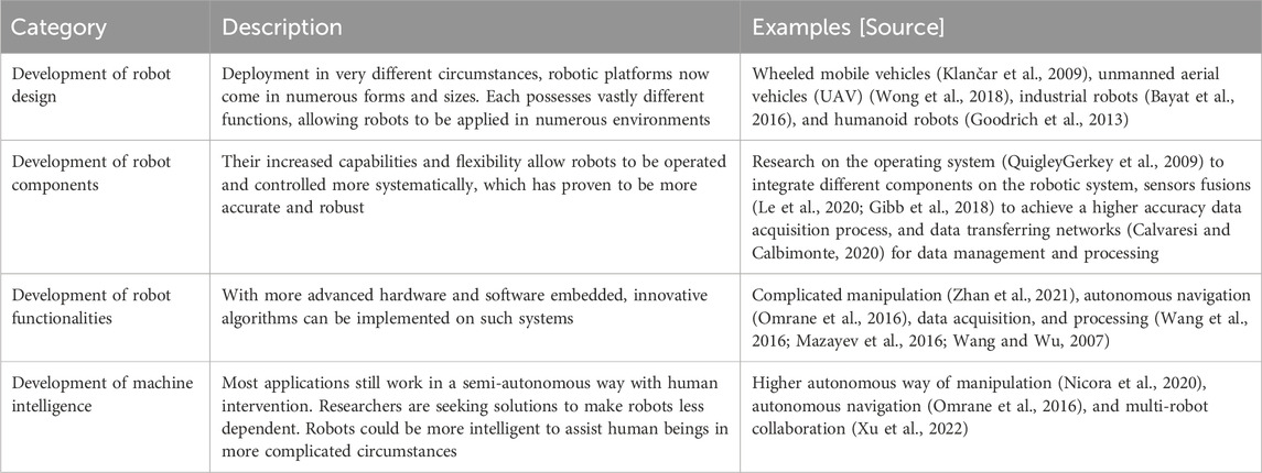
TABLE 1. Summary of different categories of research areas and development of robotic systems in the construction industry.
Construction robots are a subset of industrial robots used for building and infrastructure construction (Elattar, 2008) designed for single-task operations, typically in a dynamic but still controlled environment (Feng et al., 2015). Automating construction would be helpful, particularly in settings where human presence is dangerous or problematic. Repetitive and labor-intense tasks, such as bricklaying, painting, loading, and bulldozing, are good candidates for automation. Using robots can assist in making construction sites less labor-intensive and creating safer work environments.
Table 2 summarizes some typical uses of robots in the construction industry. Although much research has been conducted to supplement these categories of construction robotic platforms, few have utilized these findings to systematically develop the integration of hardware and software, the operation environment, automatic control, and communication network for such systems to advance the functionalities of existing construction robotic applications. Thus, the usage of robotic applications in the construction industry is not as extensive as in comparison with any other field. Several challenges contribute to the limited adoption of robots in construction, including the variability of construction tasks and projects, resistance to change within the industry, insufficient training and knowledge, high initial costs, and the lack of a standardized framework. To address some of these challenges, a fundamental solution involves creating a guide tailored for non-robotic experts in the construction sector. This guide aims to facilitate the seamless integration of robotic and automation technologies into construction-related tasks, ultimately boosting their widespread use. By providing specific usage cases and considering the diverse perspectives of stakeholders, this guide equips individuals interested in adopting robots with a generic yet comprehensive procedure. Such an approach allows them to build their applications effectively and leverage the advantages offered by robotic systems in diverse construction scenarios. There is plenty of room for researchers to investigate how to integrate these subareas into a higher-level application to see how they perform in the real world to facilitate non-robotic experts in the construction sector (e.g., project managers or contractors) interested in the implementation of a solution for their various needs that could benefit from automation (i.e., robotic implementation).
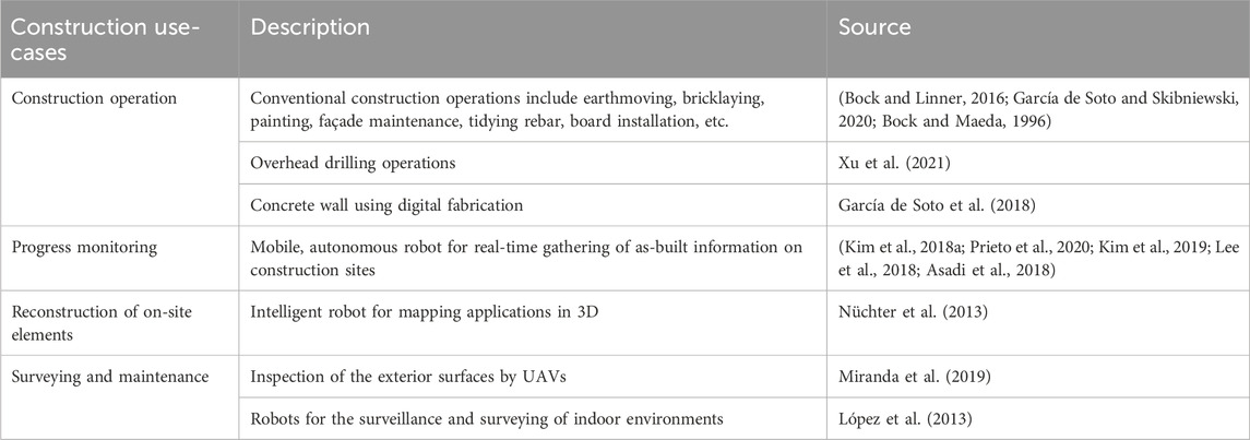
TABLE 2. Summary of robots used for different construction applications.
2.2 Robotic morphology in the construction industry
To better help the researchers focus on developing integrated robotic systems within the construction environment, robots can be classified according to how automated platforms are developed and operated in the construction domain. Those categories are summarized below.
2.2.1 Single-task construction robots (STCRs)
The use of single-task robots aims at simplifying the complicated construction process. They were designed preliminarily for one specified construction process, such as painting, material delivery, and bricklaying (Gharbia et al., 2020). STCRs are mainly designed to substitute or supplement human physical activities with repetitive activities, which do not require extra effort to control the robots for desired motions and trajectories during the operation. They can finish the tasks automatically with many iterations. However, they are preprogrammed and more suitable for a static working environment with all variables set up. They can only handle the problem that has been pre-defined in their working schemes. In most cases, because of the preprogrammed settings and the working space requirement, the environment needs to be consistent to allow duplication of the same trajectory in a pre-defined working space. Also, considering the safety of workers, these systems cannot work simultaneously with the workers on the site. Besides, setting up such systems is also time-consuming, significantly reducing the productivity gains from automation (Bock and Linner, 2016). In general, for better usage in the construction industry, construction robots need to be more flexible with easier usage and higher dynamical sensing capabilities.
2.2.2 Teleoperated systems in construction
Teleoperated systems have been introduced to the construction domain to allow flexibility in handling different situations for construction tasks. These systems make it easier for the workers to control the robots. In telerobotics, the machine does not operate autonomously but is under the control of a human operator. The operator does data sensing, interpretation, and cognitive activities such as task planning (La et al., 2014). Telerobotics could significantly reduce the uncertainties in designing and preprogramming. These telerobotic systems make it more reliable for the robots to work in a dynamic and constantly evolving environment such as a construction site. Moreover, they significantly reduce testing time when the application needs to be changed to something different. However, the drawback is also apparent: these systems are semi-autonomous and require high expertise for robotic knowledge, which could not easily be implemented on the actual site. The effective utilization of construction robots demands a workforce equipped with specialized knowledge in robotics, automation, and technology integration. Skilled workers not only enhance the overall productivity and performance of robotic applications but also contribute to the safe and optimal use of these technologies on construction sites. In light of this, investing in training programs and fostering a culture of continuous learning becomes crucial. However, the investment in training is high-cost and time-consuming. In a well-established industry such as construction, stakeholders are also skeptical about the productivity gained through the automation process, so there is a need for robotic systems to be more robust so they can be fully utilized and add value to construction sites (Javaid et al., 2021).
2.2.3 Programmable construction machines
Programmable automation allows machine configurations and operation sequences to change based on signals sent from electronic controls (Ding et al., 2018). With a programmable automation system, machine operations and sequences can be preprogrammed into different functionalities. Besides, programmable construction machines can use an electronic representation of a portion of the construction site where their work will be conducted to control all or part of the machine’s operation (Saidi et al., 2016). The final goal of this kind of system is to allow the operators to vary the task to be accomplished within certain constraints by choosing from a preprogrammed menu of functions or by teaching the machine a new function. This introduces a critical shift along two distinct dimensions. Firstly, they alleviate the demand for significant physical effort traditionally required in various tasks. Secondly, they target a reduction in human cognitive effort, streamlining processes and allowing human workers to focus on higher-order decision-making rather than routine, repetitive tasks. Explicitly addressing these dimensions becomes paramount in assessing the impact and effectiveness of programmable robots in both enhancing efficiency and optimizing the allocation of human skills within the given context. For example, Ding et al. (Nvidia, 2022) introduced a programmable hydraulic controller for a robotic excavator to adapt to dynamic changes during excavation. Prieto et al. (2020) proposed an integrated programmable robotic platform to extract building elements from IFC to generate a progress report in changing environments. Programmable machines are a further development of those two categories mentioned above to achieve a higher autonomous level of control, which is easier to use on the job site and more suitable to address the challenges in adoption. The final goal of these systems is to build up a collection of robotic construction activities, a standardized database or reference that could be adopted into many construction tasks in different projects. However, a systematic framework needs to be developed to guide the integration of different robotic activities and functionalities to build up a programmable machine. This is a challenge for construction practitioners without particular expertise in robotics to set up sensors, autonomous control schemes, and communication networks for different robotic components. To the best of the authors’ knowledge, there is no general framework to guide construction practitioners to build up their own programmable machines from scratch. Thus, a guide is needed to boost the wide usage of the integrated robotic system on the construction site.
2.3 Challenges for robot design in the construction industry
2.3.1 Sensing capabilities for construction environments
Automated and robotized manufacturing facilities are typically structured environments since the machines and evolving products either stay in their pre-defined locations or move on predesigned and typically fixed paths (Milberg and Tommelein, 2003). However, construction robots have more complicated situations than the robotic systems used in factories/manufacturing. Construction sites in the construction industry can typically be considered unstructured since they constantly evolve, dramatically changing shape and form in response to construction tasks. Building components are moved around without fixed paths or laydown/staging areas. Various physical connections are established through improvisation in response to in situ conditions, making tight tolerances hard to maintain and enforce (M et al., 2005). This means that pre-defined actions may not be suitable for all circumstances as construction sites and workspaces constantly change. Therefore, robots need to perceive the environment and understand how to react to changes (Feng et al., 2015). For example, Mantha and García de Soto (Mantha et al., 2019; Mantha and García de Soto, 2022) utilized fiducial markers to allow the accurate positioning of robots. Wang et al. (2020) used digital twins to update the construction environment and guided robots to execute tasks as human-instructed in the virtual environment. Prieto et al. (2021) proposed an autonomous robot equipped with different sensors to collect data to automatically assess the state of construction. Ko et al. (2022) integrated V-SLAM with an RGBD camera on an autonomous Unmanned Aerial Vehicle (UAV) platform for concrete crack detection on construction sites. They are embedded with new technologies, and a more advanced construction robot platform could address the dynamic changes, allowing other robotic activities to be integrated to achieve a higher autonomous level.
2.3.2 Control and locomotion of mobility
In manufacturing, factory robotics typically involves robotic platforms that are generally stationary. Precision is achieved by controlling the pose of the moving (and evolving) product, and the robots are programmed to manipulate the products through fixed trajectories. Thus, from a mobility and cognitive perspective, a factory robot has little responsibility and autonomy (Feng et al., 2015). However, this spatial relationship is reversed in construction. A construction robot must travel to its next workstation, perceive its environment, account for tight tolerances, and perform manipulation activities. This places significant mobility and cognitive burden on a robot intended for construction tasks, even if the job itself is repetitive. The mobility control of construction robots is also a trending topic in recent research. For example, Lee et al. (1997) proposed a fuzzy logic controller that allows robots to navigate massive construction sites based on feedback from real-time sensors; Xu et al. (2022) suggested using reinforcement learning to teach the robots to learn from their past failure and experience to learn the skills to locate themselves. Researchers have put much effort into enhancing the performance of the mobility of the robots, and advanced strategies such as enhanced sensing capabilities, localization, and mapping algorithms are the priority to address the problem. However, only a few investigate how these algorithms can benefit the whole construction process in a broader view. For example, Chen et al. (2020) analyzed the robotic mobility and manipulation performance when working with workers in an intelligent warehouse system to order and place bricks. Xu et al. (2021) analyzed the performance of a drilling robot and identified some challenges to productivity gains because of the complicated setup procedure and time-consuming localization process using a total station. However, they did not devise a solution to enhance the whole process. Almost none analyze the mobility performance and benefits from a systemic view. Instead, they only evaluate the accuracy and performance of the mobility strategies. There is plenty of room for researchers to optimize mobility strategies more autonomously and systematically.
2.3.3 Autonomy: higher-autonomous intelligent systems
An autonomous construction robot is expected to accomplish its task(s) within a defined scope, with minimal or no human intervention (Saidi et al., 2016). However, in most of the literature mentioned above, most of the applications work with semi-autonomous configurations, which require the efforts of human beings to assess and inspect. For example, Elfes et al. (1998) investigated a semi-autonomous airship for environmental monitoring with humans giving orders on actions to take in navigation; Sutter et al. (2018) proposed a semi-autonomous bridge inspection system that needs humans to inspect and modify the position for scan taken, the semi-autonomous manner separate the localization and data acquisition process, which added an extra burden to system management and data transfer. Previous research also shows that few of them investigate how to automate the process of defined construction tasks with added extra functions. For example, Mantha and García de Soto (2019) proposed a system using fiducial markers to localize the robotic system and do the path planning according to the data collected. The proposed system is in a semi-autonomous setting, which uses static markers with human instructions, which adds much complexity when using such a robotic system. In a higher-level autonomous setting, the construction robot is expected to adapt to its sensed environment, formulate plans for executing its task, and re-plan as necessary. The intelligent construction robot should also determine when its tasking is not executable and request assistance (Eiben et al., 2021). All these processes need an integrated control system and communication networks to execute different services or actions when given a specific scenario. Previous research has never found a way to solve this problem. This paper proposes a general framework to handle and standardize the process (see Section 3). The application is tested using an integrated autonomous platform for data collection (see Section 4).
2.4 Existing construction robotic platforms
Given the wide range and availability of robotic platforms, a distinction needs to be made between the framework they are based on. In the following subsections, the terms “closed” and “open-source” platforms are used to refer to platforms that keep the development of the algorithms private and to those that make all the development available, respectively.
2.4.1 Existing “closed” platforms
Construction robots are generally creating interest in the academic and industrial domains. Gradually, more and more robotic applications have been brought into the construction industry to assist construction activities. Many researchers have tried to adopt robotic systems mostly based on robotic platforms that are commercially available in the market. However, most commercial products are “closed” products, meaning that the company behind the product’s manufacturing might not be willing to fully disclose the working principles of the control behind their platform or even allow the end user to modify it to suit their application better. A software development kit (SDK) is sometimes provided, although it often does not provide access to all the platform’s capabilities. For example, Brosque and Fischer (2022) proposed a reference framework to evaluate the performance of multiple commercial products on the construction site and assess their safety, productivity, and quality performance. Xu et al. (2021) used a case study to evaluate the performance of the drilling robot “Jaibot” to drill holes for the installation hangers on the MEP systems according to the BIM models and suggested possible enhancements to the platform. Wetzel et al. (2022) used Boston Dynamics’ four-legged robot “Spot” to test the quality and efficiency of LiDAR Scanning on Active Construction Sites. Tribelhorn and Dodds (2007) evaluated the opportunities and limitations of an “iRobot” platform for construction research and tasks.
These cases show that the adoption of robots on construction sites is increasing, but it remains low compared to other fields. The current robots used in construction are limited to one specific task on a small scale. On top of that, the functionalities provided heavily rely on the stock features and characteristics of the commercial products. Most currently developed platforms are of general usage in multiple fields, with only some specifically designed for a construction task. Such as the Tybot for tying rebars (García de Soto and Skibniewski, 2020) or the Canvas platform aimed at drywall finishes for wall painting (Cronin et al., 2019). Using a general usage system would need further development or modification to make it suitable for a construction site, which results in tedious work for researchers and contractors to investigate.
Previous research highly depends on the commercially developed robotic platform, which is limited by the manufacturer’s options and equipment. They are looking into adopting the existing platforms into construction projects instead of finding a way to systematically connect different construction functionalities into a more generic robotic platform. Commercially available platforms come hassle-free and ready to be used with minor tweaking, but they often do not suit 100% of the client’s needs.
2.4.2 Existing “open-source” platforms
In contrast, open-source platforms are more customizable to the required needs and applications. With the possibility of access to open-source platforms, researchers have plenty of room to focus on developing the robotic platform themselves (Adán et al., 2019). For example, some researchers have started to integrate new navigation algorithms to advance autonomous control in dynamic evolving environments (Kim et al., 2018a; Labbé and Michaud, 2014; Kohlbrecher et al., 2011), or using the reprogrammed platform with new sensing modules to extract information for 3D mapping and reconstruction of the construction site (Kim et al., 2018b; Kurazume et al., 2017; Prieto et al., 2017), or investigating the communication working schemes between different components embedded on top of the robotic platforms (Mayoral et al., 2017). Still, someone getting started in robotics could easily get lost with the number of variables to be considered. There are limited studies that introduce in a detailed way the steps to develop an open system customized for a particular application. With researchers still focusing on the robotic platforms available in the market, the lack of resources for construction experts to develop robots has limited the widespread integration of construction robotic applications. No previous literature in the construction domain provides a systematic approach to developing such platforms. Thus, a guide for construction practitioners without expertise in robotics would greatly benefit the development and integration of robotics in the construction field.
A comparison is summarized in Table 3 to help understand the different characteristics between the “closed” and “open-source” platforms.
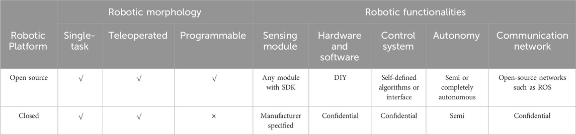
TABLE 3. Comparison of “open-source” and “closed” construction robotic platforms.
2.5 Comparison with the state-of-the-art works
As stated in the previous literature, to build a construction robot, all the aspects need to be considered, including the robotic platform to be built on, the hardware and software integration, the autonomy the robot requires, different sensing modules on board (i.e., sensors and computers), the control strategies and systems, and communication network. However, to the author’s knowledge, previous studies on construction robots mainly focused on one or two specific aspects instead of giving a general integration of all the elements required to build the system. Table 4 gathers information from state-of-the-art studies on construction robots, summarizing if the elements discussed above are present in their research work. This paper aims to integrate all elements to design a construction robot from scratch, which provides easy-to-follow steps, allowing construction practitioners who do not have a robotic background to be able to design their own robot based on the application requirements.
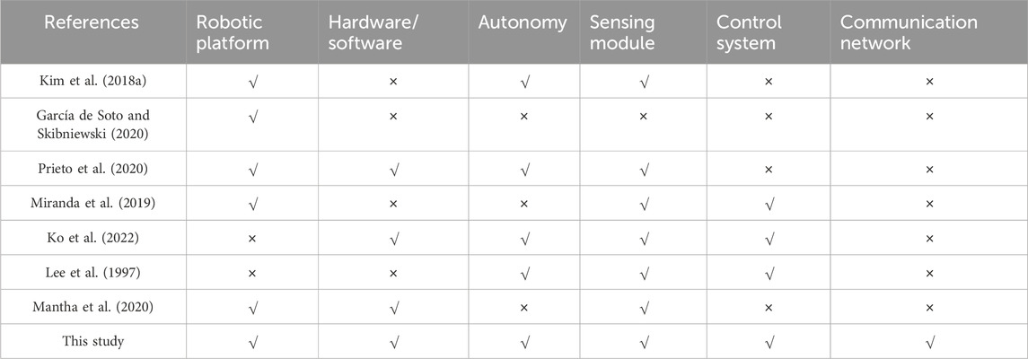
TABLE 4. Summary of the state-of-the-art applications in construction robots.
3 Methodology
Robotic platforms come in different forms and are embedded with various functionalities to achieve different goals. This section provides a systematic methodology to cover all the possible choices and assist construction professionals interested in determining which robotic platform might be useful in their projects. Our methodology aligns with the principles of Design Science Research (DSR) (Hevner et al., 2004), following an iterative process of design, development, and evaluation to address the identified challenges. The main steps of the methodology are summarized in Figure 1. The principal component is the actual design of the robotic platform, which consists of an iterative process ensuring that all the robot components are chosen considering their specific purpose. Each step is explained in detail in this section.
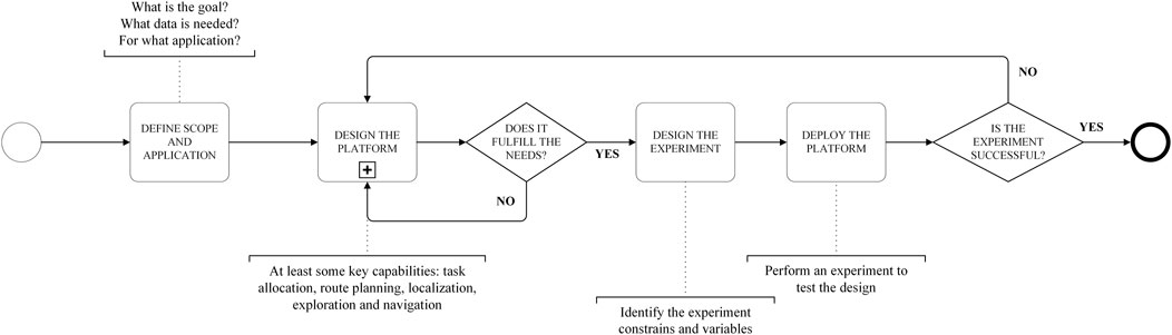
FIGURE 1. Overall process of the proposed methodology.
3.1 Define the scope and application
The first step is to define the scope and the goals/application of the robotic platform. Questions such as what is the robot intended to do? Or what tasks will be performed by the system? Should be addressed in this step. This will be a determinant factor for the other choices regarding the actual design.
The definition and thinking process of the application itself follows its own process, but that is beyond the scope of this study, focusing solely on the design process of the robotic platform. Therefore, it is assumed that the application and scope of the robotic platform are clear and well-defined at this point. For example, in the case of an application focused on masonry work, the goal of the robot should be clearly defined and not too broad, like laying bricks with a set of pre-defined parameters (i.e., length, width, height, and position of the wall to be built).
3.2 Design the platform
Despite the specifics of the individual applications defined in the previous step, a robotic platform with minimum autonomy must fulfill a set of key capabilities that will be common in every case (Mantha et al., 2020). First, to achieve the desired application, the platform needs to allocate tasks, e.g., breaking down the main goal into smaller tasks that need to be processed in a given order. For example, the robot needs to be able to locate itself within the work environment, knowing at every moment the relationship between the local coordinate system of the platform and the global coordinate system of the scenario. This can be achieved by different means, such as passive localization (Nahangi et al., 2018; Park and Hashimoto, 2009) (i.e., markers, April tags, RFID), or active localization (Fox et al., 1998) (i.e., visual odometry, particle filters). Following localization, both navigation and route planning are required as well. If the robot is to perform an autonomous, unsupervised movement, it must be equipped with the necessary sensors and algorithms. To ensure that all the different aspects are being considered, a more detailed breakdown of this step is shown in Figure 2. The following subsections provide a detailed explanation of each step.
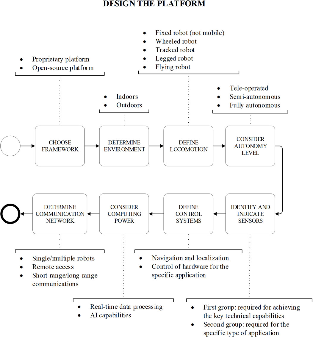
FIGURE 2. Detailed process followed for designing the platform.
3.2.1 Choose framework
In some cases, if the application does not require unusual or very customized requirements, the options available from robotic service retailers (e.g., Boston Dynamics, iRobot, Universal Robots) could suffice the needs of the user. However, for the most part, proprietary platforms ready to be deployed are often limited to the capabilities provided by the developer/manufacturer, with little room for expansion or customization. Some advantages of said platforms are that they do not require an operator with robotics knowledge or special skills to set up and deploy the platform for the desired application.
On the other hand, going for an open-source platform or even developing one from scratch offers way more customization and freedom regarding hardware components and overall control. For a platform to be fully open-source, not only the Operating System (OS) of the devices controlling the platform needs to be open-source, but also the middleware running on that OS. The OS manages the interaction between the different hardware components through device drivers. The middleware, however, is a framework that facilitates implementing a complex distributed application involving many interacting components and logic. The most popular middleware used in robotics is the Robot Operating System (ROS) (Bock and Linner, 2016). ROS is an open-source middleware system dedicated to robots, with the first version (ROS1) widely spread throughout the research community, providing multiple tools for researchers to control every aspect of a robotic platform. The next and improved version, ROS2, is building upon the feedback from the community and improving on its predecessor’s faults, such as the cybersecurity component. Other alternatives are rising in popularity, such as the NVIDIA Isaac Middleware (Nvidia, 2022), Robot Construction Kit (Rock) (Rock-robotics, 2022), Urbi (Softbank Robotics Europe, 2022), and Orca (Orca-robotics, 2022; Feng et al., 2015), to name a few. Arduino platforms are also popular within the hobbyist community, given how widespread they are and the flexibility they offer. Although they could be used for specific and simple tasks, such as IoT and communicating different sensors throughout the construction site, they do not scale properly with bigger and more complex systems. Based on the authors’ experience, ROS is the most commonly used in the research community and the industry and, therefore, the one used in this study.
Proprietary commercial and open-source platforms have advantages and disadvantages, and a detailed comparison is beyond the scope of this study. However, the three main differentiating factors are the cost, customization capacity, and skills required for deployment. In general, the proprietary commercially available platform is costlier and less customizable but easier to deploy and has the added benefit of technical support availability. For this study, customization and flexibility are preferred, so only an open-source platform is considered.
3.2.2 Determine environment
An important aspect to consider is whether the application to be performed by the platform happens indoors or outdoors. This will not significantly affect the software part of the robot but will most likely affect any choice regarding the hardware of the robot.
The most significant consideration is to be able to deal with the weather conditions in the case of an outdoor scenario. Climate can present itself in extreme and challenging conditions in specific parts of the world, such as very high or very low temperatures, high humidity and rain, often unsuitable for most hardware components. There are some specific ratings, such as Ingress Protection (IP) ratings for outdoor devices to get a minimum waterproof enclosure, such as IP65, IP66, and IP67, that need to be considered, providing certifications that the device to be included in the robotic platform is both dustproof and waterproof.
The type of scenario can also affect how the robotic platform interacts with the environment, not only in how it traverses the scenario but also in how it collects data from it. Certain outdoor scenarios require different characteristics for the locomotion aspect, and some specific sensors, such as 3D scanners, are often not suitable for large open outdoor scenarios, not only for their range limitations but also for their poor performance with open skies or direct sunlight exposure (Tredinnick et al., 2019). In the example of a robot aimed to perform masonry work, both outdoor and indoor environments should be taken into consideration. In addition, debris on the floor should be expected, as well as the presence of heavy dust conditions.
3.2.3 Define the locomotion system
Once the environment has been defined, the locomotion of the robot can be determined. Depending on the morphology of the robot by the way it moves (or its lack of movement) through the scenario, robotic systems can be categorized into fixed robots (non-mobile platforms), wheeled robots, tracked robots, legged robots, and flying robots (Quintana et al., 2021; Quintana et al., 2021).
Fixed robots are not that common in the construction industry, except for applications where pre-fabricated structures are being used (i.e., gantry systems and fixed robots for 3D concrete printing applications).
Flying robots are often limited to outdoor scenarios, with specific cases able to fully perform in indoor applications (Grzonka et al., 2009; Sato et al., 2016). They are often best performing when height is the controlling factor, such as when inspecting building facades or where a top-down aerial view is needed. The control and localization of the flying robot often rely on external elements, such as the availability of GPS.
Wheeled robots, on the other hand, are the most common in indoor scenarios. It does not mean they are not suitable for outdoor environments, but they are more reliable and less challenging for indoor environments. They are often easy to control and offer reliable and high-precision maneuverability. A distinction can be made for holonomic platforms equipped with mecanum or omnidirectional wheels. These allow the robotic platform to perform movements in the X and Y-axes (i.e., lateral movements). They are exclusively limited to environments with relatively flat surfaces where the grip between the floor and the wheel is high enough for the holonomic action to take effect. These configurations often perform poorly in environments with a high presence of loose gravel or sand.
Tracked robots are better for more challenging environments that cannot ensure a flat surface or enough friction with the wheels (Ducros et al., 2017; Lever et al., 2006). Tracks offer a more reliable movement for scenarios rich in obstacles and different elevations, allowing the robotic platform to surpass small obstacles or uneven terrain. However, they do not provide as much precision and maneuverability as wheels.
Finally, legged robots are a good compromise if the robot is to perform both indoors and outdoors. Legged locomotion offers the best solution for dealing with obstacles of all kinds, even going up and down stairs. This, however, can be a more expensive choice, not to mention the hardest to control due to the natural complexity of the different gaits available for a legged robot (Erden and Leblebicioǧlu, 2008; Plagemann et al., 2008). With the proper control, they can be as precise (or even more) as a holonomic wheeled platform. However, when speed is a requirement, a legged robot might not be able to achieve high speeds reliably and efficiently compared to a wheeled or tracked robot. In the case of a masonry robot, a compromise between precision and reliability to navigate in rough terrain needs to be achieved. Tracks are good in terms of achieving linear movement accuracy, which would be the main movement needed for a brick-laying robot, and they would be ideal to surpass any debris present in the working area.
3.2.4 Consider the autonomy level
The level of autonomy of the robotic platform will greatly impact the choice of the sensors and the computing power and communication devices on board the robot. Three main categories can be differentiated in this aspect: completely manual (teleoperated), semi-autonomous, and completely autonomous robots (Mantha et al., 2020).
Teleoperated robots are the simplest ones regarding control and the least demanding regarding sensing capabilities. A distinction must be made between teleoperation with the direct sight of the robot and remote teleoperation without the direct sight of the robot (Chen et al., 2007; Lin and Kuo, 1997). The latter needs enough sensing capabilities to provide feedback to the user controlling the platform, whereas the first does not need sensors at all. Despite being simple in sensory load and control algorithms, they require a skilled operator to control them. They are mostly used in monitoring and rescue missions in hazardous environments where the presence of human beings is not an option.
Semi-autonomous robotic platforms are the most commonly used ones. They do offer some autonomous capabilities that may vary depending on the application, but they do rely on human interaction for some other tasks, such as charging, objective identification, or adjusting multiple parameters throughout the application. Some of the most common tasks performed autonomously are movements and anything that involves trajectory planning, repetitive actions, or task allocation (Van Henten et al., 2002; Peungsungwal et al., 2001).
Completely autonomous robots can perform the entire process without human intervention. Ideally, the robot gets an initial environment setup once, and there is no longer a need to interact with the platform again. Completely autonomous robots need a higher payload of sensors and require a greater complexity when designing the control system since they have to be reliable even when facing dynamic environments. In the case of a brick-laying robot, some manual process would be needed in order to keep the robotic platform supplied with materials (i.e., bricks). The brick-laying process could be designed to be made completely autonomous.
3.2.5 Identify and choose sensors on board
In general, sensors are needed to collect the necessary data from the surroundings and for the robot to react to the environment. For the sensory load of the robotic platform, two main groups of sensors can be differentiated. The first group consists of all the necessary sensors to fulfill the minimum key capabilities previously indicated, i.e., mapping, localization, and navigation tasks. These are referred to as basic sensors. Sensors within this group can be of different types, but they all have in common the ultimate goal of providing feedback from the environment to either the robot or the user behind its control. Some of the most typical sensors for this purpose are wheel encoders (to provide odometry), inertial measurement units (IMU), a global positioning system (GPS), light detection and ranging (LiDAR), ultrasonic ranging devices, or cameras. The second group comprises specific sensors for the application (i.e., task-specific sensors). These could be any type of sensor and should be chosen based on the specific application. For example, if the objective of the robotic is to monitor the comfort level of a building (Quintana et al., 2021), it would have to be equipped with CO2, humidity, and temperature sensors, to mention a few. In some cases, the line between the first and second groups can be fuzzy since sensors from the first group could also be used as task-specific sensors. However, the distinction is made based on their usage for the minimum key capabilities (i.e., mapping, localization, and navigation tasks). If a sensor is specifically used to fulfill these capabilities, then it belongs to the first group, even though the data coming from the sensor could also be used for task-specific applications.
In general, the more sensors there are, the better equipped the platform will be. However, three main limiting factors determine the number of sensors a platform can carry. These factors are the platform payload, the computing power needed to handle all the incoming data, and the cost of the devices. For example, if the platform does not have a big payload capacity, specific sensors, such as long-range 3D scanners, can be too heavy to be combined with other sensors. Taking into consideration these three factors, for more complicated tasks, it is advisable to split the sensory load amongst multiple robotic agents (Prieto et al., 2021). In the particular case of a brick-laying robot, sensors regarding autonomous close-range movement would be needed (i.e., LiDAR and short-range ultrasonic ranging devices). A way to detect the 3D space in front of the robot to keep track of the building wall would be needed (i.e., LiDAR or depth camera). In addition, a robotic arm and a specifically designed gripper would be needed to handle the bricks and lay them properly.
3.2.6 Define control systems
Having defined the tasks needed to fulfill the application requirements, the level of autonomy the robotic platform needs to have, the sensors on board the platform to fulfill all the required capabilities, and the proper control system to handle everything needs to be implemented.
As mentioned in Section 3.2.1, choosing the right middleware is a key step to fully control the robotic platform. Most middleware options come with predesigned and ready-to-use solutions that can take care of most of the basic capabilities a robot must be able to perform, such as odometry computations, localization and mapping (e.g., SLAM), or autonomous navigation. For the specifics of the application, most of the commercially available sensors come prepared with a Software Development Kit (SDK) that allows the user to write specific code to control the sensor. In most cases, a driver can be written for the interaction of the proper middleware with the sensor, allowing the robot platform to fully control all the devices on board.
3.2.7 Consider computing power
The computing hardware and software components play a central role in implementing the logic and ensuring the proper behavior of autonomous robots. In terms of size and complexity, hardware components can range from small microcontroller units (MCUs) to full-featured computers. MCUs have limited computing capacity but are equipped with several interfaces to connect sensors, actuators, and external peripherals. They are, thus, used for low-level interfacing with such devices. Embedded computers are more powerful. They typically run OSs, such as Linux, but they have limited support for direct interfacing with sensors and actuators. Common architectures in complex applications include several MCUs and computers.
The amount of computing power to be added to the robotic platform will be determined by different factors, such as the amount of data coming from the different sensors on board or how much data processing will happen in real-time on the platform. Given the rapid growth of Artificial Intelligence (AI) and Machine Learning (ML) algorithms in data processing, it is safe to assume that any platform requiring real-time data processing will need a fair amount of computing power to run these algorithms. Therefore, the addition of Graphical Processing Units (GPUs) that are better suited for this type of processing also needs to be considered. A brick-laying robot, for example, would not prioritize high-speed real-time computing, and therefore, GPUs would not be necessary.
3.2.8 Determine the communication network
There are a few elements that the communication network needs to fulfill, such as providing reliable and stable communication between the user and the robot or between the robot and any other agent it needs to interact with (e.g., a data server or another robot). The characteristics of this basic communication network will be determined by some of the aspects mentioned before, such as the level of autonomy the platform needs to have or the environment.
The complexity of the communication network for the robotic platform will increase with the number of agents within the network (Doriya et al., 2015). This is why choosing the number of robots (if a robotic swarm is needed) or elements within the network (e.g., multiple command stations or servers) is crucial to designing a manageable and reliable communication network.
Different communication topologies are suggested for robot communication, such as star, tree, ring, mesh, line, bus, and hybrid topologies (Amiripalli and Bobba, 2019). In addition, there are also different possible models of communication. For example, they can have a master, rotating token, etc. Determining the appropriate communication system depends on mission circumstances and communication hardware and limitations, such as distance of units from each other, communication media and technologies, bandwidth limitations, delay, noise, communication speed, etc.
Another aspect to consider is having the robot confined to a closed, local communication network or having Internet exposure. The former ensures a controlled communication environment, limiting exposure to external risks and maintaining data security. However, it restricts the robot’s access to broader data resources and may limit its functional capabilities, especially in tasks requiring real-time, global data. The latter provides robots an Internet exposure through 5G connectivity. This aligns them more closely with concepts like the Internet of Things (IoT) and the Internet of Everything (IoE). The advantages include real-time data access, remote control capabilities, and integration with a wide array of online services, sensors, and databases. However, this approach raises significant concerns regarding cybersecurity, data privacy, and the need for robust, uninterrupted internet connectivity.
3.3 Test and deploy the platform
Once the platform has been defined based on the design requirements indicated in Section 3.2, it is necessary to test that the result can fulfill all the specifications laid out in the initial stage. This process is carried out at the end of the design process, so there is an opportunity to test the full system every time something new gets implemented. During this iterative process, based on the test results, if the platform is successful and performs as intended, then it can be deployed. If the test is not successful, the process loops back to the beginning of the design process to modify whatever is necessary before another test.
Once the design is completed and the test has been successful, the platform can be deployed for its intended application, ensuring that enough user training is provided to the people who would be in contact with the platform, both in terms of use and safety.
4 Implementation: development of a semiautonomous data collection system
To illustrate the use of the methodology presented in Section 3, this section compiles the required steps to develop a platform for automating the collection of data (e.g., taking scans including point cloud data, RBG, and thermal images) on construction sites based on open-source platforms and flexible systems (i.e., not dependent on proprietary/closed products). The reason for choosing this particular application is because data collection robots have been applied to different construction activities such as progress monitoring, construction operating, surveying, reconstruction of on-site elements, and maintenance of buildings. However, there is a gap in integrating these two processes to advance the functionality of such systems. Besides, the development of data acquisition hardware, such as cameras, IMU, Lidar, and Lasers, provides researchers with higher dimensional data streaming in the data acquisition and inspection process, which requires extra expertise to process and manage data in different formats (Milberg and Tommelein, 2003). Relevant research on on-site construction data collection platforms. A summary is provided in Appendix A.
4.1 Define the scope and application
The particular application is data collection in construction sites. General tasks such as data collection for progress monitoring purposes are an ideal application for autonomous robots since, for the most part, they do not require very structured or extremely dynamic task requirements. In this case, the developed platform will have to autonomously traverse a construction environment during all the different stages of the construction process, from the early stages of the construction to operations and maintenance. While navigating the construction site, the robot will have to be able to collect different types of data from the environment, mainly 3D geometric data, (color) pictures, and infrared information. The application requires the platform to be completely autonomous during operation, with only minimum interaction from the human operator while setting the task. Based on this, the platform needs to have the following characteristics:
• Good mobility in small indoor spaces.
• Limited interaction from a human operator.
• The ability to add sensors and peripherals to collect data from the site (i.e., have enough payload).
• The ability to customize software and algorithms in control of the robot’s behavior.
• Have sufficient battery life to perform the application.
• Comply with any required safety requirements.
4.2 Design the platform
There are multiple commercially available robotic platforms (FARO, 2022; Leica, 2022); however, for purposes of this study, customization and flexibility are preferred, so only an open-source platform is considered, and discussion of off-the-shelf robotic platforms is not part of the scope.
4.2.1 Choose the proper framework
An integrated framework is needed to set up communication between different modules of the robotic platform and the information flow between them. Since the level of customization and control needed for the specific application is relatively high, an open architecture ROS-based platform has been chosen. The basic hardware corresponds to a SUMMIT-XL robotic platform from Robotnik (2022). Different sensors and customizations (Figure 3), discussed in detail next, have been added to the basic platform, making it suitable to address the above characteristics.
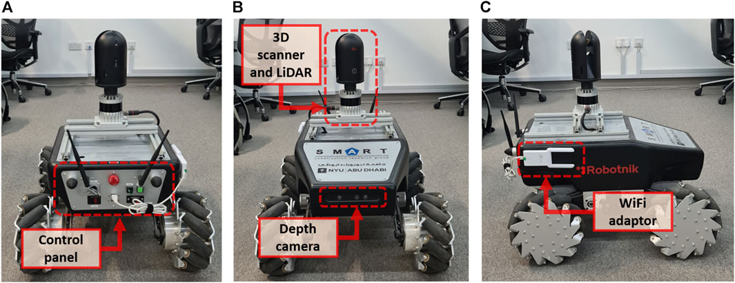
FIGURE 3. Main components of the robotic platform. (A) Rear view showing the control panel, (B) front view of the robot with the depth camera, 3D scanner, and LiDAR, and (C) side view (right) showing the Wi-Fi adaptor.
4.2.2 Determine environment
The robotic platform will mostly collect data in indoor environments for the specific required application. In general, most of the inspections during the construction stage (except for the very early ones) will happen indoors. It is expected that some of the key aspects of the environment where the robotic platform will perform most of the time are a high presence of walls and narrow passages, flat floors with a minimum amount of debris or small clutter, and well-illuminated areas. The environment can differ depending on the stage of the lifecycle of the building, such as an ongoing construction site or during operation (e.g., Figure 4). Different stages will present different challenges, such as the presence of obstacles (static or moving) that might affect mobility.
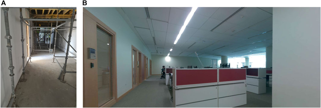
FIGURE 4. Example views of places where the platform is expected to be used during the different construction stages. General view of (A) ongoing construction site and (B) occupied office building.
4.2.3 Define the locomotion system
In general, construction environments contain narrow passages, so it is expected that the platform will require high precision in its movements. Legged platforms are a good option but have limitations related to maintenance and are generally more expensive than wheeled ones. A holonomic platform would allow the robotic system to maneuver amongst the narrow passages and avoid any clutter or obstacles that might be present. Using this locomotion, the robot can move in both directions of the planar space (Figure 5), presenting a wider range of movements in relatively small spaces without having to perform complicated maneuvers. This particular feature becomes very useful when traversing narrow door frames and avoiding clutter on the construction site. However, this approach might be challenging in spaces where a lot of clutter or obstructions are expected or in floors with poor traction (such as places with sand or gravel flooring conditions).
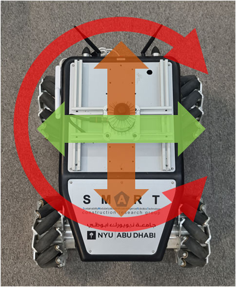
FIGURE 5. Diagram of the movement axis for a holonomic platform (X-axis: orange arrow, Y-axis: green arrow, yaw movement: red arrow).
4.2.4 Consider the autonomy level
In general, a high level of autonomy is required. That means that not only can the platform navigate from one point to another in an autonomous manner, but ideally, the entire data collection process is autonomous, too. Only the bare minimum interaction from the human operator at the beginning of the process (e.g., providing enough data (i.e., the BIM model) to the robotic platform to perform the assessment) is the input required. For simplicity, it is expected that the platform will not be controlled remotely from outside the construction site; instead, all the interactions with the platform will be within the site. Another important aspect to consider when defining the autonomy level is the battery life of the robotic platform. The autonomous process might get interrupted if the battery life is not long enough for the platform to perform one full operation. The SUMMIT-XL platform has a standard battery life of 4–5 h, which should be sufficient to perform standard data collection in a construction environment.
4.2.5 Identify and indicate sensors on board
The desired level of autonomy will be fundamental for the selection of the 1) type of sensors for mobility or basic sensors (i.e., those used for navigation/localization/positioning, etc.) and 2) data collection or task-specific sensors (e.g., thermal camera, scanner, etc.).
4.2.5.1 Basic sensors
The first group comprises sensors responsible for localization and autonomous navigation. Construction sites are characterized by being unstructured and dynamic. This creates extraordinary challenges for robots to localize and navigate in such environments, which is why specialized sensors must be added to solve this challenge. Since the robot will be working in a dynamic and cluttered environment, it must be able to avoid dynamic and static obstacles while executing a given task.
The most common way to solve both localization and navigation is by Simultaneous Localization and Mapping Algorithms (SLAM). There are many implementations of 2D and 3D SLAM with different sensor configurations. Most hardware configurations employ a dedicated sensor for 2D SLAM and other sensors to gather 3D data. The SUMMIT-XL platform comes with a 2D Hokuyo LiDAR, limited to dynamic and complex environments. To improve that, the 2D LiDAR was replaced by a 3D Ouster OS1 LiDAR (Figure 6). That LiDAR has a minimum range of 0.8 m and a maximum range of 120 m, a vertical field of view (FOV) of 33.2° and a 360° horizontal FOV, with a maximum of 5.2 million points per second and a precision of up to ±0.7 cm. The LiDAR is used to give the robotic platform a detailed enough awareness of the surroundings, which can be used for both localization and navigation purposes, as well as dynamic obstacle avoidance (Figure 7). On top of this, the localization of the robot is improved by fusing the LiDAR data with the odometry from the wheels’ encoders and the Pixhawk Inertial Measurement Unit (IMU) installed in the robot.
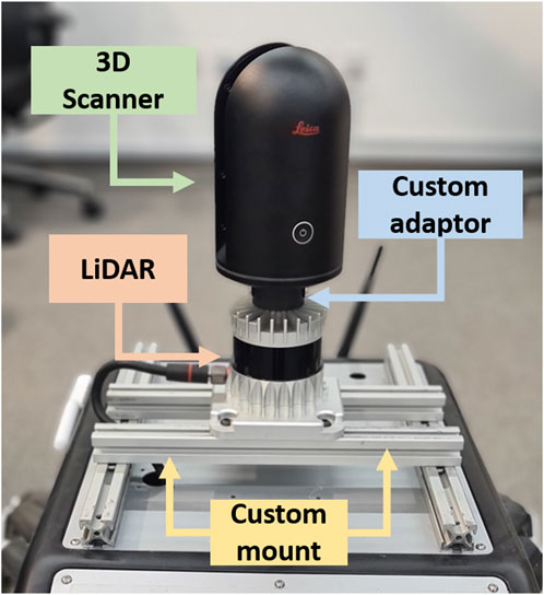
FIGURE 6. Sensory load on board the robot, used for data collection and navigation.
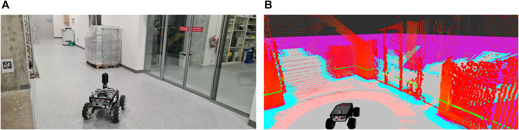
FIGURE 7. (A) View of the robot in the scenario. (B) Real-time visualization of the sensors’ data in Rviz.
4.2.5.2 Task-specific sensors
For the second group of sensors, the application requires geometric 3D data, color, and infrared information. For this particular purpose, the Leica BLK360 3D scanner (Figure 6) was chosen. The 3D scanner can collect data with a high FOV (360° × 300°) and a much higher 3D point accuracy (8 mm @ 20 m). The maximum range of the BLK360 is 60 m, which is enough for the application requirements. It runs on batteries and weighs just 1 kg, which makes it ideal to be mounted on top of mobile robots. The scanner not only gathers 3D points but is also equipped with three 5 MP cameras to generate an HDR full-dome RGB image and a thermal infrared FLIR camera to provide thermal information. The data collected from the BLK360 is also complemented with an RGB-D camera installed in the front of the robot that can be used when single pictures need to be taken for monitoring purposes. The depth camera is an Orbbec Astra with a maximum range of 8 m, a FOV of 60°H x 49.5°V x 73°D, and an RGB and depth resolution of 640 × 480.
A special mount was designed to adapt the BLK360 on top of the OS1 LiDAR to use the full 360° of the LiDAR (Figure 8). A series of iterations and rapid prototyping was needed before the final piece was mechanized in aluminum so as not to interfere with the cooling process of the OS1 LiDAR. The first prototype fixed the BLK360 behind the LiDAR, occluding the rear part of the robot. The final piece allows for the BLK360 to be mounted without occluding any of the available FOV of the OS1 LiDAR, taking advantage of the low weight of the 3D scanner. A custom modular rail system was also designed to mount the sensory system onboard the mobile robot.
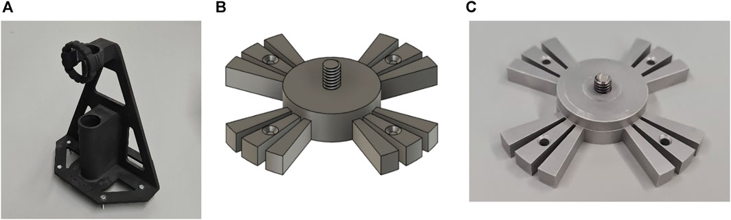
FIGURE 8. (A) First prototype designed for the BLK360 mount. (B) 3D CAD model of the final design. (C) Final piece mechanized in aluminum.
In order to automate the data collection, a specific and customized ROS node was created to control the BLK360 3D scanner using the API provided by the vendor; this makes the 3D scanner control accessible through the platform and puts all the devices inside the platform inside the same framework (ROS), making it very convenient for the platform to autonomously control all the sensors on board.
4.2.6 Define control systems
As previously indicated, the control algorithms/drivers can be classified into the same two categories (i.e., basic and task-specific sensors).
The developed platform in this study needs to perform SLAM to obtain a map of the environment and localize itself within the created map for further autonomous navigation. ROS already provides developed solutions for all these applications, requiring minimum configuration to adapt the algorithm to the particular hardware of the robotic platform. Thanks to how ROS is structured and configured (i.e., nodes and topics), the developed solutions are designed to work with the topics containing a certain type of information (i.e., point cloud topics, laser scan topics, odometry topics). As long as the data is properly formatted in a ROS message structure, the source of said data is of no relevance to the ROS node running the application. For example, there are multiple solutions for the SLAM problem, such as Gmapping (Grisetti et al., 2007), Google Cartographer (Hess et al., 2016), or HectorSlam (Kohlbrecher et al., 2011). Gmapping has been chosen in this study due to its robustness, good performance, and minimal adjustments required for working results out of the box (i.e., the only necessary changes to make are those specific to the robot, such as the name of the topic publishing the scan information and the names of the different transformation systems). Gmapping generates an obstacle map of the environment that will be used for the robotic platform to autonomously navigate the scenario. To further increase the accuracy of the localization, an Adaptive Monte Carlo Localization (AMCL) approach was chosen (Fox et al., 1999). Algorithms based on particle filters, such as AMCL, have been used for many years and have been proven reliable in providing accurate position estimates right out of the box. The position estimate provided by the AMCL is further fused with the odometry coming from the wheels’ encoders and the data from the IMU to have an even more accurate position estimation. The navigation is solved using a global planner and a local planner. The global planner is in charge of computing an obstacle-free path from point A to point B. The mission of the local planner is to compute the necessary velocity commands to ensure the robotic platform follows the path generated by the global planner and deals with dynamic obstacles that might not be present in the global path. For this particular application, two well-known algorithms available in the ROS default navigation stack have been used for their reliability and performance. The Navfn algorithm serves as the global planner, using a Dijkstra approach (Dijkstra, 1959) to compute the path to follow. A Time-Elastic-Band approach (TEB) (Rösmann et al., 2012) was chosen as the local planner because of its performance with holonomic systems like the one developed in this study. Both algorithms are good to work right out of the box with the minimum changes mentioned before (i.e., topics and transformation systems’ names), although the TEB local planner can be further tuned to suit the specific environment where the robot is going to perform for an even increased performance and efficiency in the navigation. For this particular application, the navigation system was completely unaware of the quality of the data being collected by the 3D scanner. If one of the requirements of the system is to minimize the travel time of the robot, further optimization and tuning need to be done in the navigation system, so that it tries to maximize the amount of information collected on each scan location. Some of the main specific parameters used for this robotic platform are summarized in Table 5.
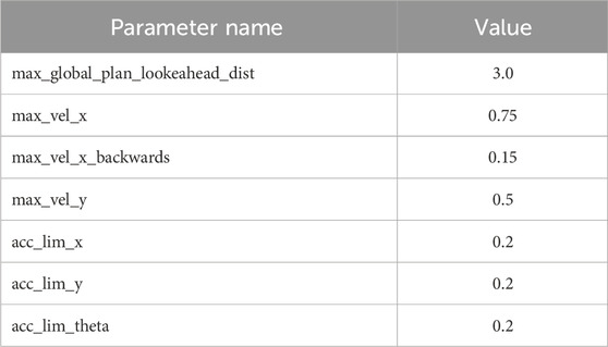
TABLE 5. Some of the specific parameters used for the TEB local planner with the implemented robotic platform.
For the task-specific sensors, two main ROS nodes are being used. The first one controls the Ouster OS1 LiDAR. The ROS node used here is provided by Ouster and consists of a driver that allows the ROS system to interact with the data flow from the LiDAR. The node publishes all the available information (i.e., the actual point cloud, reflectance information, 2D panoramic maps) in the form of different topics that can be used by the other nodes responsible for the SLAM and the navigation. The published information, in the form of a 3D point cloud, is further processed to condense all the information into a single 2D slice at the height of the LiDAR that can be used with the AMCL localization algorithm. This has been done with the help of the “pointcloud_to_laserscan” ROS node (wiki.ros.org, 2022a).
The BLK360 3D scanner is also controlled by a ROS node. For this particular case, an SDK has been provided by Leica, but a ROS wrapper (i.e., a node created to interface non-ROS code with the rest of the system) had to be developed to integrate the scanner with the ROS system. The developed ROS node needs to be able to interact with the BLK360 and fulfill at least the following characteristics:
• Perform a measurement (3D scan, RGB, and thermal data) with the ability to choose the concerned parameters (i.e., choose what data needs to be collected and its resolution).
• Download the measurement to the robot computer.
• Perform the necessary data processing (i.e., colorizing the 3D point cloud with the RGB images).
• Data management operations (i.e., download, manage, delete, list, and rename data inside the BLK360).
• Device management operations (i.e., get device and battery status).
The node has been developed in C++, following the latest ROS coding conventions (wiki.ros.org, 2022b), and it can integrate the BLK360 with the ROS system, providing all the previously stated functionalities in the form of ROS services. These developed ROS services can be called by any other ROS node, allowing the robotic platform full control over the 3D scanner. The overall structure of the node can be seen in Figure 9.
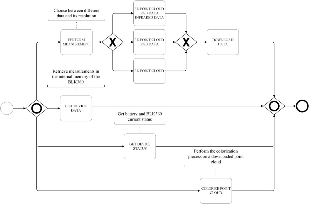
FIGURE 9. Overall structure of the developed ROS node to act as a wrapper with the BLK360 SDK.
Finally, another ROS node was developed to integrate everything. In other words, this node is responsible for allocating all the different tasks within the data collection process. It allows the user to interact with the created map to indicate the different positions where the robot needs to stop and collect data and creates a state machine to control the robotic platform at all times. The state machine is responsible for systematically sending the robot to the different goals, making sure the robot has successfully reached the goal and is in a stop position, and commanding the BLK360 scanner to perform a measurement. The robot returns to an initial resting position when all the goals have been visited.
In addition to the previous ROS nodes, there are other multiple nodes in charge of all the different behaviors and control of the different components on board the robot. A simplified version of the ROS network with the main nodes discussed here is shown in Figure 10. Figure 10 shows the main nodes responsible for the data collection process (grey ovals) and their respective data published in different topics (orange rectangles).
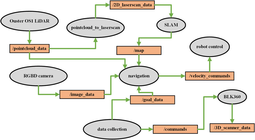
FIGURE 10. Simplified diagram of the ROS network.
4.2.7 Computing power
The robot has an internal computer controlling all the sensors on board and the main algorithms for navigation and data collection. The computer is an embedded PC with an Intel i3 8th Gen processor, 8 GB of RAM, and 250 GB of SSD storage. Since the purpose of the platform, for now, is data collection, there is not going to be heavy real-time data processing. The processing of the collected data would happen ad hoc on an external device. With that in mind, the equipped computer has plenty of power to run the ROS architecture in control of the robot navigation and data collection. The computer is remotely accessed to give commands and retrieve the collected data.
4.2.8 Communication network
The robotic platform has its own closed (i.e., without Internet access) Wi-Fi network for all internal components’ communication and remote control. A good understanding of the internal communication structure among the different components is needed. In this case, the integration of the different components and communications links within the robotic platform is divided into five levels to better illustrate how all the components are connected with each other (Figure 11). These five levels represent different aspects of the communication network, starting from the hardware and physical connections (Level 0) to a more abstract level, such as data visualization (Level 4). These layers have been established for pure visualization and explanation purposes. In reality, the barriers between the different layers are fuzzy, and everything belongs to the same network.
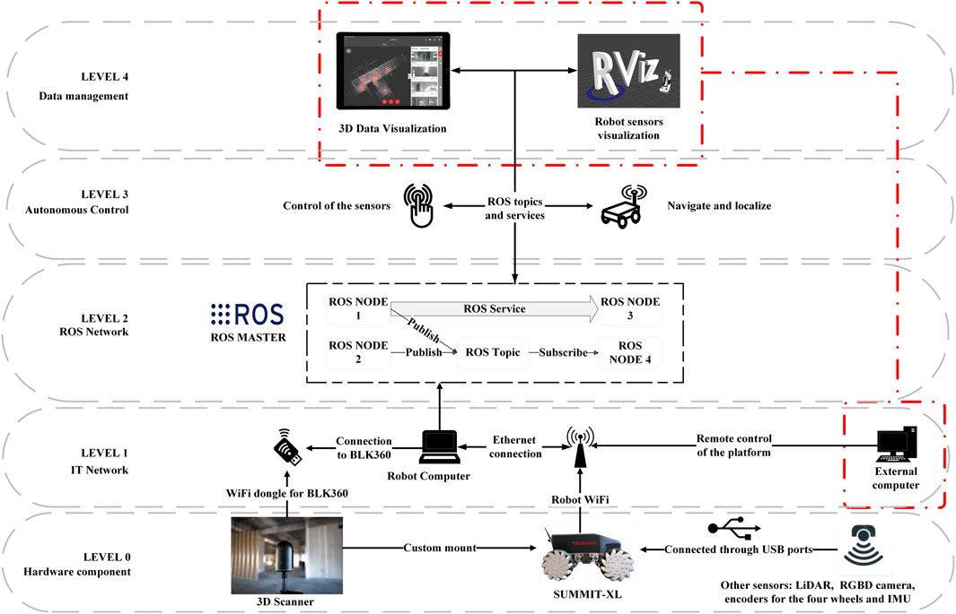
FIGURE 11. Structure of the different external and internal communication strategies of the robotic platform.
Level 0 comprises the hardware components of the robot, both for acquiring data and interacting with the environment (i.e., sensors and actuators). Within this level, devices such as the 3D scanner and all the sensors embedded in the robot (i.e., LiDAR, RGBD camera, encoders, and IMU) can be found. Most of the sensors on board the robot are connected through USB. The robotic platform itself is also part of this level, housing all the components and providing locomotion.
Level 1 corresponds to the IT network of the system. The robotic platform is equipped with a router that creates a network (both wired and wireless) to communicate all the different components with each other. The embedded computer is connected via ethernet to the internal router to make everything accessible within the network created by the platform. One of the downsides of the BLK360 is that it only offers wireless communication to interact with the device. Since the embedded computer of the robot does nothave a wireless adaptor, a Wi-Fi dongle was needed to communicate the computer with the 3D scanner. To provide a Human-Machine Interaction (HMI) interface to control the system and visualize the data, an external computer can be connected to the network.
Level 2 contains the Robot Operating System (ROS) network. The key component within the ROS network is the presence of a master node. For other nodes to exchange information and communicate with each other, a master needs to supervise all the information exchange. In this case, the internal robot computer runs the master node, and any external computer can connect to the ROS network to interact with it. This interaction works both ways, allowing the robotic platform to listen to any command from the external computer and the external computer to visualize any data coming from the robotic platform. Inside the ROS network, besides the master node, multiple other nodes are in charge of all the different sensors and robot capabilities, as seen in the previous sections. All these nodes exchange information with each other in the form of messages that use topics as transport. The nodes can also request actions amongst each other by means of services.
Level 3 involves the semi-autonomous control of the robot. Within this level, the different ROS nodes responsible for task allocation and autonomous applications request information from the nodes controlling the sensors and send commands to the nodes controlling the actuators (i.e., wheels).
Level 4 is the data management layer. A graphical user interface (GUI) can be used to interact with and visualize the collected data. The default GUI used in ROS is RViz. It runs on the external computer to visualize any real-time information from the robotic platform, to not overload the processing being performed in the embedded robot computer.
4.3 Deployment and testing
Since the developed platform is intended to work on every stage of a building’s lifecycle, it has first been tested in a finished and in-operation building, simulating a maintenance operation. Data collection during the maintenance stage could be useful for monitoring the building over time and if a refurbishment operation is planned and there is no updated BIM model. The chosen site test is an office space in one of the buildings for a university campus. Since the BIM model of the building is not available, the robotic platform was used to generate a 2D map of the floor (Figure 12) that was used for the autonomous navigation of the robot.
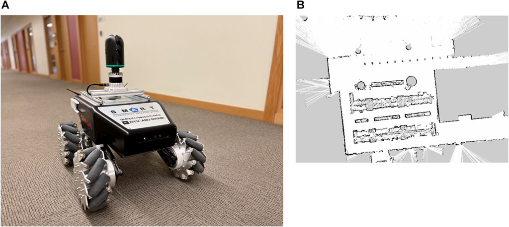
FIGURE 12. (A) View of the robotic platform performing an autonomous mission of collecting data (using the 3D scanner) in an office space. (B) Image of the obstacle map generated by the robot during SLAM while autonomously collecting data.
The robotic platform autonomously navigated through multiple positions scattered around the entire floor (Figure 13) to completely digitize and collect not only 3D geometric information but also RGB images used to colorize the resultant point cloud.
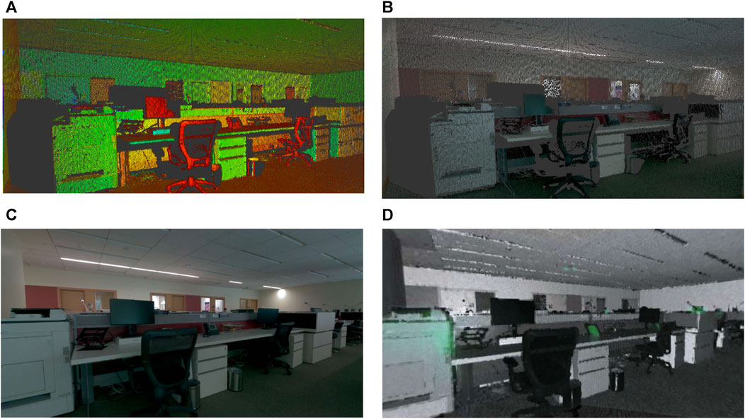
FIGURE 13. (A) 3D geometry from the point cloud with reflectance information, (B) 3D colored point cloud collected during the data collection inspection, (C) panorama RGB image, and (D) thermal data collected.
The entire process for the inspection took approximately 30 min and successfully digitized the entire office space (approx. 500 m2) with minimal human intervention: just one individual to indicate the waypoints and monitor the robot. The resultant floor point cloud (Figure 14) has more than 50 million points and could be used to autonomously generate an as-is model of the current state of the building, which could be useful for maintenance purposes or future refurbishment operations. To further assess the quality of the collected data, a quantitative analysis regarding the density of the point cloud, percentage of noise collected by the scanner, and point cloud coverage has been added to the paper. As can be seen from the results in Table 6, the difference between the point count before and after noise removal is minimal, meaning that the original point cloud did not account for much noise overall. A point cloud’s volume is measured based on the volumetric space enclosed within a set of neighboring points. By using a 0.077 m search radius, the results obtained for the density are summarized as the mean and standard deviation resulting from the volumetric space analysis. Finally, the per-cell population ratio represents the average distribution of points in equal-sized cells with a magnitude of 0.05 m.
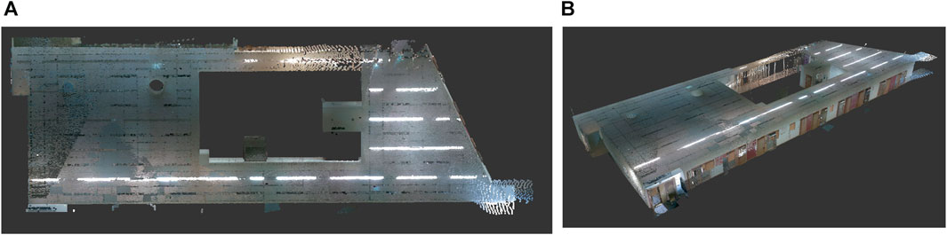
FIGURE 14. (A) Top-down view (i.e., floor layout). and (B) perspective view of the 3D colored point cloud collected in the office space.
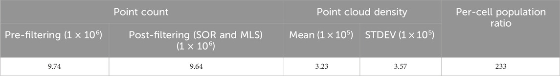
TABLE 6. Quantitative analysis regarding the quality of the collected point cloud.
5 Limitations
This study is based on an open-source framework. Although it shows many benefits, such as easy implementation and flexibility in integrating customized functionalities, it only considers a limited comparison with existing commercial applications (e.g., the Spot). Benchmarking is needed to explore these open platforms with close commercial products on their pros/cons, cost, time, and data quality to evaluate the proposed system’s performance. With regards to the case study, the focus is on the development of the robotic system and the integration of the required sensors/peripherals and not providing an exhaustive analysis of the data collected. The part related to the collection of data is limited to showcasing the type of data obtained with the laser scanner in a semi-autonomous manner, and only basic information about the characteristics and quality of the data has been provided.
For the operating system inside the proposed method, although the ROS framework allows researchers to collaborate and build upon the work of others instead of having to develop everything from scratch, it also means that integrating all the different components requires expert personnel to have everything working together. The tested data collection process is autonomous based on a ROS node developed from the commercial laser scanner’s SDK, as shown in the implementation section. However, the detailed explanations of developing such functionalities and using the data are beyond the scope of this study. Future studies will detail how to automate and integrate the data collection process with other robotic functionalities and show how to automatically process and post-process the data to benefit construction activities.
The cybersecurity aspects have not been considered in this study. Most open-source solutions, such as ROS1, focus on a rapid development strategy, leaving behind important aspects such as robustness and safety while facing data breach attacks (Sonkor et al., 2022).
6 Conclusion and outlook
This study presents a methodology to guide the development of robotic platforms and promote the use of such platforms in the construction industry by researchers or practitioners interested in automation and robotics in construction applications. Whereas the implemented and discussed methodologies are not novel, to the authors’ knowledge, there is no study dealing with the development of the entire platform and the integration of all the different available technologies that construction practitioners can use. This could be a valuable resource for anyone wanting to incorporate a similar flexible system that is not dependent on proprietary/closed products in construction projects, as well as providing extensive information about the software and hardware requirements required to develop a robotic platform, challenges to be aware of, and benefits of doing so. Given how challenging the construction industry is, all the different variables have been taken into account. For this reason, the developed framework (in its entirety or some specific parts) could also be generalized to other industries and fields.
Following the proposed methodology, a robotic platform has been developed to collect data from indoor environments in a semi-autonomous way to validate the proposed methodology. The platform is equipped with the necessary sensors and capabilities to fulfill the requested application, and since it is based on an open framework, it is possible to keep adapting and evolving the platform based on future requirements for different applications. Main elements related to the control system, in particular, the development of the ROS nodes, should help researchers and practitioners demystify such open-source middleware systems. The developed platform was used to collect data from an office space.
Future work will be focused on addressing one of the biggest limitations of the developed platform, which is the low-security ROS1 offers against anyone attempting to hack into it or steal any of the information collected by the system. An immediate upgrade to the system would be to migrate from ROS1 to ROS2, which already offers a more secure environment regarding confidentiality, integrity, and accessibility of the operations and data collected. A more in-depth comparison between ROS1 and ROS2 will be done in the future to study the viability of the upgrade based on the time and costs required to do so. Alternatives to a ROS-based system are also being tested, such as NVIDIA Isaac Sim, which could provide an alternative for an industry scenario. Further experimentation by applying this methodology to more complex scenarios will be addressed in the future as well, making sure that the method is scalable to bigger scenarios with more complex tasks to be performed.
Since reliable and robust systems often rely on expensive equipment, such as 3D LiDARs, it would greatly contribute to the robotics’ adoption to further research equally accurate techniques based on more affordable and accessible hardware, such as depth cameras. In addition, further research needs to be done to deal with the full integration of such robotic systems in heavily standardized environments such as the construction field, ensuring the safety and reliability of all the integrated systems, as well as the ethical implications that integrating such systems could bring to the table. To solve this, the establishment of proper international standardization rules that specifically address robotic systems needs to be implemented.
Data availability statement
The original contributions presented in the study are included in the article, further inquiries can be directed to the corresponding author.
Author contributions
SP: Conceptualization, Data curation, Formal Analysis, Investigation, Methodology, Validation, Writing–original draft, Writing–review and editing. XX: Data curation, Formal Analysis, Investigation, Methodology, Validation, Writing–original draft, Writing–review and editing. BG: Conceptualization, Data curation, Formal Analysis, Investigation, Supervision, Validation, Writing–original draft, Writing–review and editing.
Funding
The author(s) declare that no financial support was received for the research, authorship, and/or publication of this article.
Acknowledgments
This work has benefited from the collaboration with the NYUAD Center for Sand Hazards and Opportunities for Resilience, Energy, and Sustainability (SHORES), and with the NYUAD Center for Interacting Urban Networks (CITIES), funded by Tamkeen under the NYUAD Research Institute Award CG001. Thanks to Dr. Oraib Al Ketan and his team from the Advanced Manufacturing Core Technology Platforms at NYUAD, Nikolaos Giakoumidis from the Kinesis CTP lab, and Nas Gopee for their support during the rapid prototyping of the customized parts used for the robotic platform.
Conflict of interest
The authors declare that the research was conducted in the absence of any commercial or financial relationships that could be construed as a potential conflict of interest.
The author(s) declared that they were an editorial board member of Frontiers, at the time of submission. This had no impact on the peer review process and the final decision.
Publisher’s note
All claims expressed in this article are solely those of the authors and do not necessarily represent those of their affiliated organizations, or those of the publisher, the editors and the reviewers. Any product that may be evaluated in this article, or claim that may be made by its manufacturer, is not guaranteed or endorsed by the publisher.
Supplementary material
The Supplementary Material for this article can be found online at: https://www.frontiersin.org/articles/10.3389/fbuil.2024.1307728/full#supplementary-material
References
Adán, A., Quintana, B., and Prieto, S. A. (2019). Autonomous mobile scanning systems for the digitization of buildings: a review. Remote Sens. (Basel) 11, 306–313. doi:10.3390/rs11030306
Amiripalli, S. S., and Bobba, V. (2019). An optimal TGO topology method for a scalable and survivable network in IOT communication technology. Wirel. Personal Commun. Int. J. 107 (2), 1019–1040. doi:10.1007/S11277-019-06315-Z
Asadi, K., Kalkunte Suresh, A., Ender, A., Gotad, S., Maniyar, S., Anand, S., et al. (2020). An integrated UGV-UAV system for construction site data collection. Autom. Constr. 112, 103068. doi:10.1016/j.autcon.2019.103068
Asadi, K., Ramshankar, H., Pullagurla, H., Bhandare, A., Shanbhag, S., Mehta, P., et al. (2018). Vision-based integrated mobile robotic system for real-time applications in construction. Autom. Constr. 96, 470–482. doi:10.1016/J.AUTCON.2018.10.009
Bayat, B., Bermejo-Alonso, J., Carbonera, J., Facchinetti, T., Fiorini, S., Goncalves, P., et al. (2016). Requirements for building an ontology for autonomous robots. Ind. Robot. 43 (5), 469–480. doi:10.1108/IR-02-2016-0059
Bock, T. (1996). “Robotic assembly system for computer integrated construction,” in Proceedings of the 13th international symposium on automation and robotics in construction. Editor M. K Maeda (Tokyo, Japan: IAARC), 169–178. doi:10.22260/ISARC1996/0022
Bock, T., and Linner, T. (2016). “Single-task construction robots by category,” in Construction robots (Cambridge: Cambridge University Press), 14–290. doi:10.1017/CBO9781139872041.002
Bock, T., and Linner, T. (2016). Construction robots: elementary technologies and single-task construction robots, vol. 3. Cambridge: Cambridge University Press. doi:10.1017/CBO9781139872041
Brosque, C., and Fischer, M. (2022). A robot evaluation framework comparing on-site robots with traditional construction methods. Constr. Robot. 6, 187–206. doi:10.1007/s41693-022-00073-4
Calvaresi, D., and Calbimonte, J. P. (2020). Real-time compliant stream processing agents for physical rehabilitation. Sensors Switz. 20 (3), 746. doi:10.3390/s20030746
Chen, J. Y. C., Haas, E. C., and Barnes, M. J. (2007). Human performance issues and user interface design for teleoperated robots. IEEE Trans. Syst. Man Cybern. Part C 37 (6), 1231–1245. doi:10.1109/TSMCC.2007.905819
Chen, Y., Yang, C., Song, B., Gonzalez, N., Gu, Y., and Hu, B. (2020). Effects of autonomous mobile robots on human mental workload and system productivity in smart warehouses: a preliminary study. Proc. Hum. Factors Ergonomics Soc. Annu. Meet. 64 (1), 1691–1695. doi:10.1177/1071181320641410
Cronin, C., Conway, A., and Walsh, J. (2019). “State-of-the-Art review of autonomous intelligent vehicles (AIV) technologies for the automotive and manufacturing industry,” in 2019 30th Irish Signals and Systems Conference (ISSC), Maynooth, Ireland, 17-18 June 2019, 1–6.
Davila Delgado, J. M., Oyedele, L., Ajayi, A., Akanbi, L., Akinade, O., Bilal, M., et al. (2019). Robotics and automated systems in construction: understanding industry-specific challenges for adoption. J. Build. Eng. 26, 100868. doi:10.1016/j.jobe.2019.100868
Dijkstra, E. W. (1959). A note on two problems in connexion with graphs. Numer. Math. (Heidelb) 1 (1), 269–271. doi:10.1007/BF01386390
Ding, R., Zhang, J., Xu, B., and Cheng, M. (2018). Programmable hydraulic control technique in construction machinery: status, challenges and countermeasures. Autom. Constr. 95, 172–192. doi:10.1016/j.autcon.2018.08.001
Doriya, R., Mishra, S., and Gupta, S. (2015). “A brief survey and analysis of multi-robot communication and coordination,” in International Conference on Computing, Communication and Automation, Greater Noida, India, 15-16 May 2015, 1014–1021. doi:10.1109/CCAA.2015.7148524
Doumbia, M., and Cheng, X. (2020). State estimation and localization based on sensor fusion for autonomous robots in indoor environment. Computers 9 (4), 84. doi:10.3390/computers9040084
Ducros, C., Hauser, G., Mahjoubi, N., Girones, P., Boisset, L., Sorin, A., et al. (2017). RICA: a tracked robot for sampling and radiological characterization in the nuclear field. J. Field Robot. 34 (3), 583–599. doi:10.1002/ROB.21650
Eiben, A. E., Hart, E., Timmis, J., Tyrrell, A. M., and Winfield, A. F. (2021). “Towards autonomous robot evolution,” in Software engineering for robotics. Editors A Cavalcanti, B Dongol, R Hierons, J Timmis, and J Woodcock (Cham: Springer International Publishing), 29–51. doi:10.1007/978-3-030-66494-7_2
Elattar, S. M. S. (2008). Automation and robotics in construction: opportunities and challenges. Emir. J. Eng. Res. 13 (2), 21–26.
Elfes, A., Bueno, S. S., Bergerman, M., and Ramos, J. G. (1998). “A semi-autonomous robotic airship for environmental monitoring missions,” in Proceedings. 1998 IEEE International Conference on Robotics and Automation (Cat. No.98CH36146), Leuven, Belgium, 20-20 May 1998, 3449–3455. doi:10.1109/ROBOT.1998.680971
Erden, M. S., and Leblebicioǧlu, K. (2008). Free gait generation with reinforcement learning for a six-legged robot. Rob. Auton. Syst. 56 (3), 199–212. doi:10.1016/J.ROBOT.2007.08.001
FARO (2022). FARO trek. Available at: https://www.faro.com/en/Products/Hardware/Trek-3D-Laser-Scanning-Integration (Accessed November 07, 2022).
Feng, C., Xiao, Y., Willette, A., McGee, W., and Kamat, V. R. (2015). Vision guided autonomous robotic assembly and as-built scanning on unstructured construction sites. Autom. Constr. 59, 128–138. doi:10.1016/J.AUTCON.2015.06.002
Fox, D., Burgard, W., Dellaert, F., and Thrun, S. (1999). “Monte Carlo localization: efficient position estimation for mobile robots,” in Proceedings of the National Conference on Artificial Intelligence, 343–349.
Fox, D., Burgard, W., and Thrun, S. (1998). Active Markov localization for mobile robots. Rob. Auton. Syst. 25 (3–4), 195–207. doi:10.1016/S0921-8890(98)00049-9
Gambao, E., Balaguer, C., and Gebhart, F. (2000). Robot assembly system for computer-integrated construction. Autom. Constr. 9 (5–6), 479–487. doi:10.1016/S0926-5805(00)00059-5
García, S. G., and García, M. G. (2019). Industry 4.0 implications in production and maintenance management: an overview. Procedia Manuf. 41, 415–422. doi:10.1016/j.promfg.2019.09.027
García de Soto, B., Agustí-Juan, I., Hunhevicz, J., Joss, S., Graser, K., Habert, G., et al. (2018). Productivity of digital fabrication in construction: cost and time analysis of a robotically built wall. Autom. Constr. 92, 297–311. doi:10.1016/j.autcon.2018.04.004
García de Soto, B., and Skibniewski, M. (2020). “Future of robotics and automation in construction,” in Construction 4.0 (London: Taylor and Francis Group), 289–306. doi:10.1201/9780429398100-15
Gharbia, M., Chang-Richards, A., Lu, Y., Zhong, R. Y., and Li, H. (2020). Robotic technologies for on-site building construction: a systematic review. J. Build. Eng. 32, 101584. doi:10.1016/J.JOBE.2020.101584
Gibb, S., La, H. M., Le, T., Nguyen, L., Schmid, R., and Pham, H. (2018). Nondestructive evaluation sensor fusion with autonomous robotic system for civil infrastructure inspection. J. Field Robot. 35 (6), 988–1004. doi:10.1002/rob.21791
Goodrich, M., Crandall, J., and Barakova, E. (2013). Teleoperation and beyond for assistive humanoid robots. Rev. Hum. Factors Ergonomics 9, 175–226. doi:10.1177/1557234X13502463
Grisetti, G., Stachniss, C., and Burgard, W. (2007). Improved techniques for grid mapping with rao-blackwellized particle filters. Robotics, IEEE Trans.23, 34–46. doi:10.1109/TRO.2006.889486
Grzonka, S., Grisetti, G., and Burgard, W. (2009). “Towards a navigation system for autonomous indoor flying,” in 2009 IEEE International Conference on Robotics and Automation, Kobe, Japan, 12-17 May 2009, 2878–2883. doi:10.1109/robot.2009.5152446
Hess, W., Kohler, D., Rapp, H., and Andor, D. (2016). “Real-time loop closure in 2D LIDAR SLAM,” in 2016 IEEE International Conference on Robotics and Automation (ICRA), Stockholm, Sweden, 16-21 May 2016, 1271–1278. doi:10.1109/ICRA.2016.7487258
Hevner, A. R., March, S. T., Park, J., and Ram, S. (2004). Design science in information systems research. Available at: https://www.jstor.org/stable/25148625.
Javaid, M., Haleem, A., Singh, R. P., and Suman, R. (2021). Substantial capabilities of robotics in enhancing industry 4.0 implementation. Cogn. Robot. 1, 58–75. doi:10.1016/j.cogr.2021.06.001
Kim, P., Chen, J., and Cho, Y. K. (2018b). SLAM-driven robotic mapping and registration of 3D point clouds. Autom. Constr. 89, 38–48. doi:10.1016/j.autcon.2018.01.009
Kim, P., Chen, J., Kim, J., and Cho, Y. K. (2018a). “SLAM-driven intelligent autonomous mobile robot navigation for construction applications,” in Advanced computing strategies for engineering. Editors I. F. C Smith, and B Domer (Cham: Springer International Publishing), 254–269. doi:10.1007/978-3-319-91635-4_14
Kim, P., Park, J., Cho, Y. K., and Kang, J. (2019). UAV-assisted autonomous mobile robot navigation for as-is 3D data collection and registration in cluttered environments. Autom. Constr. 106, 102918. doi:10.1016/J.AUTCON.2019.102918
Klančar, G., Matko, D., and Blažič, S. (2009). Wheeled mobile robots control in a linear platoon. J. Intell. Robot. Syst. 54 (5), 709–731. doi:10.1007/s10846-008-9285-7
Ko, P., Prieto, S. A., and García de Soto, B. (2022). Developing a free and open-source automated building exterior crack inspection software for construction and facility managers. Available at: https://arxiv.org/abs/2206.09742.
Kohlbrecher, S., von Stryk, O., Meyer, J., and Klingauf, U. (2011). “A flexible and scalable SLAM system with full 3D motion estimation,” in 2011 IEEE International Symposium on Safety, Security, and Rescue Robotics, Kyoto, Japan, 01-05 November 2011, 155–160.
Kurazume, R., Oshima, S., Nagakura, S., Jeong, Y., and Iwashita, Y. (2017). Automatic large-scale three dimensional modeling using cooperative multiple robots. Comput. Vis. Image Underst. 157, 25–42. doi:10.1016/j.cviu.2016.05.008
La, H., Gucunski, N., Kee, S.-H., Yi, J., Senlet, T., and Nguyen, L. (2014). “Autonomous robotic system for bridge deck data collection and analysis,” in IEEE International Conference on Intelligent Robots and Systems, Chicago, IL, 14-18 September 2014, 1950–1955. doi:10.1109/IROS.2014.6942821
Labbé, M., and Michaud, F. (2014). “Online global loop closure detection for large-scale multi-session graph-based SLAM,” in IEEE International Conference on Intelligent Robots and Systems, Chicago, IL, USA, 14-18 September 2014, 2661–2666. doi:10.1109/IROS.2014.6942926
Le, D. V.-K., Chen, Z., and Rajkumar, R. (2020). Multi-sensors in-line inspection robot for pipe flaws detection. IET Sci. Meas. Technol. 14 (1), 71–82. doi:10.1049/iet-smt.2019.0171
Lee, J. H., Park, J., and Jang, B. (2018). “Design of robot based work progress monitoring system for the building construction site,” in 2018 International Conference on Information and Communication Technology Convergence (ICTC), Jeju, Korea (South), 17-19 October 2018, 1420–1422. doi:10.1109/ICTC.2018.8539444
Lee, S., Adams, T. M., and Ryoo, B. Y. (1997). A fuzzy navigation system for mobile construction robots. Autom. Constr. 6 (2), 97–107. doi:10.1016/S0926-5805(96)00185-9
Leica (2022). Leica BLK ARC. Available at: https://leica-geosystems.com/en-us/products/laser-scanners/autonomous-reality-capture/blk-arc (Accessed November 07, 2022).
Lever, J. H., Denton, D., Phetteplace, G. E., Wood, S. D., and Shoop, S. A. (2006). Mobility of a lightweight tracked robot over deep snow. J. Terramech 4 (43), 527–551. doi:10.1016/J.JTERRA.2005.09.002
Lin, Q., and Kuo, C. (1997). Virtual tele-operation of underwater robots. Proc. IEEE Int. Conf. Robot. Autom. 2, 1022–1027. doi:10.1109/robot.1997.614269
López, J., Pérez, D., Paz, E., and Santana, A. (2013). WatchBot: a building maintenance and surveillance system based on autonomous robots. Rob. Auton. Syst. 61 (12), 1559–1571. doi:10.1016/J.ROBOT.2013.06.012
Mantha, B., and García de Soto, B. (2019). “Designing a reliable fiducial marker network for autonomous indoor robot navigation,” in Proceedings of the 36th international symposium on automation and robotics in construction (ISARC). Editor M Al-Hussein (Banff, Canada: IAARC), 74–81. doi:10.22260/ISARC2019/0011
Mantha, B. R. K., and García de Soto, B. (2019). Task allocation and route planning for robotic service networks with multiple depots in indoor environments. Comput. Civ. Eng. 2019, 233–240. doi:10.1061/9780784482438.030
Mantha, B. R. K., and García de Soto, B. (2022). Investigating the fiducial marker network characteristics for autonomous mobile indoor robot navigation using ROS and gazebo. J. Constr. Eng. Manag. 148 (10), 4022115. doi:10.1061/(ASCE)CO.1943-7862.0002378
Mantha, B. R. K., García de Soto, B., Menassa, C. C., and Kamat, V. R. (2020). “Robots in indoor and outdoor environments,” in Construction 4.0 (London: Taylor and Francis Group), 307–325. doi:10.1201/9780429398100-16
Mayoral, V., Hernández, A., Kojcev, R., Muguruza, I., Zamalloa, I., Bilbao, A., et al. (2017). “The shift in the robotics paradigm — the Hardware Robot Operating System (H-ROS); an infrastructure to create interoperable robot components,” in 2017 NASA/ESA Conference on Adaptive Hardware and Systems (AHS), Pasadena, CA, USA, 24-27 July 2017, 229–236. doi:10.1109/AHS.2017.8046383
Mazayev, A., Correia, N., and Schutz, G. (2016). Data gathering in wireless sensor networks using unmanned aerial vehicles. Int. J. Wirel. Inf. Netw. 23, 297–309. doi:10.1007/s10776-016-0319-y
Milberg, C., and Tommelein, I. (2003). Role of tolerances and process capability data in product and process design integration. Constr. Res. Congr. 2003. doi:10.1061/40671(2003)93
Milberg, C., and Tommelein, I. (2005). Application of tolerance mapping in AEC systems. Constr. Res. Congr. 2005. doi:10.1061/40754(183)113
Miranda, J., Larnier, S., Herbulot, A., and Devy, M. (2019). UAV-Based inspection of airplane exterior screws with computer vision. Proc. 14th Int. Jt. Conf. Comput. Vis. Imaging Comput. Graph. Theory Appl. 4, 421–427. doi:10.5220/0007571304210427
Moreno, F.-A., Monroy, J., Ruiz-Sarmiento, J.-R., Galindo, C., and Gonzalez-Jimenez, J. (2020). Automatic waypoint generation to improve robot navigation through narrow spaces. Sensors 20 (1), 240. doi:10.3390/s20010240
Nahangi, M., Heins, A., McCabe, B., and Schoellig, A. (2018). “Automated localization of UAVs in GPS-denied indoor construction environments using fiducial markers,” in 2018 Proceedings of the 35th ISARC, Berlin, Germany. doi:10.22260/isarc2018/0012
Nicora, M. L., Ambrosetti, R., Wiens, G. J., and Fassi, I. (2020). Human–robot collaboration in smart manufacturing: robot reactive behavior intelligence. J. Manuf. Sci. Eng. 143 (3). doi:10.1115/1.4048950
Nüchter, A., Elseberg, J., and Borrmann, D. (2013). Irma3D — an intelligent robot for mapping applications. IFAC Proc. Vol. 46 (29), 119–124. doi:10.3182/20131111-3-KR-2043.00011
Nvidia (2022). NVIDIA isaac middleware. Available at: https://developer.nvidia.com/isaac-sdk (Accessed November 07, 2022).
Omrane, H., Masmoudi, M. S., and Masmoudi, M. (2016). Fuzzy logic based control for autonomous mobile robot navigation. Comput. Intell. Neurosci. 2016, 1–10. doi:10.1155/2016/9548482
Orca-robotics (2022). Orca. Available at: https://orca-robotics.sourceforge.net/ (Accessed November 07, 2022).
Park, S., and Hashimoto, S. (2009). “Indoor localization for autonomous mobile robot based on passive RFID,” in 2008 IEEE International Conference on Robotics and Biomimetics, Bangkok, Thailand, 22-25 February 2009, 1856–1861. doi:10.1109/ROBIO.2009.4913284
Pärn, E. A., and García de Soto, B. (2020). “Cyber threats and actors confronting the Construction 4.0,” in Construction 4.0: an innovation platform for the built environment. Editors A Sawhney, M Riley, and J Irizarry. 1st ed (London, UK: Routledge), 441–459. doi:10.1201/9780429398100-22
Peungsungwal, S., Pungsiri, B., Chamnongthai, K., and Okuda, M. (2001). Autonomous robot for a power transmission line inspection. Undefined 3, 121–124. doi:10.1109/ISCAS.2001.921261
Plagemann, C., Mischke, S., Prentice, S., Kersting, K., Roy, N., and Burgard, W. (2008). “Learning predictive terrain models for legged robot locomotion,” in 2008 IEEE/RSJ International Conference on Intelligent Robots and Systems, Nice, France, 22-26 September 2008, 3545–3552. doi:10.1109/IROS.2008.4651026
Premebida, C., Ambrus, R., and Marton, Z.-C. (2018). “Intelligent robotic perception systems,” in Applications of mobile robots. Editor E. G Hurtado (Rijeka: IntechOpen). doi:10.5772/intechopen.79742
Prieto, S., García de Soto, B., and Adan, A. (2020). “A methodology to monitor construction progress using autonomous robots,” in Proceedings of the 37th ISARC, Kitakyushu, Japan, Oct. 2020, 1515–1522. doi:10.22260/ISARC2020/0210
Prieto, S. A., Giakoumidis, N., and García de Soto, B. (2021). AutoCIS: an automated construction inspection system for quality inspection of buildings. Available at: https://www.scopus.com/inward/record.uri?eid=2-s2.0-85127551759&partnerID=40&md5=97898c34fab6d357321e53e1376ddf87.
Prieto, S. A., Quintana, B., Adán, A., and Vázquez, A. S. (2017). As-is building-structure reconstruction from a probabilistic next best scan approach. Rob. Auton. Syst. 94, 186–207. doi:10.1016/j.robot.2017.04.016
QuigleyGerkey, M. B., Conley, K., Faust, J., Foote, T., Leibs, J., Berger, E., et al. (2009). ROS: an open-source robot operating system. ICRA Workshop Open Source Softw. 3.
Quintana, B., Vikhorev, K., and Adán, A. (2021). Workplace occupant comfort monitoring with a multi-sensory and portable autonomous robot. Build. Environ. 205, 108194. doi:10.1016/J.BUILDENV.2021.108194
Reichenbach, S., and Kromoser, B. (2021). State of practice of automation in precast concrete production. J. Build. Eng. 43, 102527. doi:10.1016/J.JOBE.2021.102527
Robotnik (2022). SUMMIT-XL robotic platform from Robotnik Automation. Available at: https://robotnik.eu/ (Accessed November 07, 2022).
Rock-robotics (2022). Robot construction kit (rock). Available at: https://www.rock-robotics.org/ (Accessed November 07, 2022).
Rösmann, C., Feiten, W., Wösch, T., Hoffmann, F., and Bertram, T. (2012). “Trajectory modification considering dynamic constraints of autonomous robots,” in ROBOTIK 2012; 7th German Conference on Robotics, Munich, Germany, 21-22 May 2012.
Saidi, K. S., Bock, T., and Georgoulas, C. (2016). “Robotics in construction,” in Springer handbook of robotics. Editors B Siciliano, and O Khatib (Cham: Springer International Publishing), 1493–1520. doi:10.1007/978-3-319-32552-1_57
Sato, F., Motomura, Y., Premachandra, C., and Kato, K. (2016). “Absolute positioning control of indoor flying robot using ultrasonic waves and verification system,” in 2016 16th International Conference on Control, Automation and Systems (ICCAS), Gyeongju, Korea (South), 16-19 October 2016, 1600–1605. doi:10.1109/ICCAS.2016.7832516
Shang, Z., and Shen, Z. (2018). Real-time 3D reconstruction on construction site using visual SLAM and UAV. Constr. Res. Congr. 2018, 305–315. doi:10.1061/9780784481264.030
Softbank Robotics Europe (2022). Urbi. Available at: https://github.com/urbiforge/urbi (Accessed November 07, 2022).
Sonkor, M., Xu, X., Prieto, S., and García de Soto, B. (2022). “Vulnerability assessment of construction equipment: an example for an autonomous site monitoring system,” in Proceedings of the 39th ISARC, Bogotá, Colombia, Nov. 2022, 283–290. doi:10.22260/ISARC2022/0040
Sutter, B., Lelevé, A., Pham, M. T., Gouin, O., Jupille, N., Kuhn, M., et al. (2018). A semi-autonomous mobile robot for bridge inspection. Autom. Constr. 91, 111–119. doi:10.1016/j.autcon.2018.02.013
Tredinnick, R., Smith, S., and Ponto, K. (2019). A cost-benefit analysis of 3D scanning technology for crime scene investigation. Forensic Sci. Int. Rep. 1, 100025. doi:10.1016/J.FSIR.2019.100025
Tribelhorn, B., and Dodds, Z. (2007). “Evaluating the Roomba: a low-cost, ubiquitous platform for robotics research and education,” in Proceedings 2007 IEEE International Conference on Robotics and Automation, Rome, Italy, 10-14 April 2007, 1393–1399. doi:10.1109/ROBOT.2007.363179
Van Henten, E. J., Hemming, J., van Tuijl, B., Kornet, J., Meuleman, J., Bontsema, J., et al. (2002). An autonomous robot for harvesting cucumbers in greenhouses. Aut. Robots 13 (3), 241–258. doi:10.1023/A:1020568125418
Wang, R., Veloso, M., and Seshan, S. (2016). “Active sensing data collection with autonomous mobile robots,” in 2016 IEEE International Conference on Robotics and Automation (ICRA), Stockholm, Sweden, 16-21 May 2016, 2583–2588. doi:10.1109/ICRA.2016.7487415
Wang, X., Liang, C.-J., Menassa, C., and Kamat, V. (2020). “Real-time process-level digital twin for collaborative human-robot construction work,” in Proceedings of the 37th ISARC, Kitakyushu, Japan, Oct. 2020, 1528–1535. doi:10.22260/ISARC2020/0212
Wang, Y., and Wu, C.-H. (2007). “Robot-Assisted sensor network deployment and data collection,” in 2007 International Symposium on Computational Intelligence in Robotics and Automation, Jacksonville, FL, USA, 20-23 June 2007, 467–472. doi:10.1109/CIRA.2007.382919
Wetzel, E. M., Liu, J., Leathem, T., and Sattineni, A. (2022). “The use of Boston dynamics SPOT in support of LiDAR scanning on active construction sites,” in ISARC proceedings of the international symposium on automation and robotics in construction (Waterloo: IAARC Publications), 86–92. doi:10.22260/ISARC2022/0014
wiki.ros.org (2022a). pointcloud_to_laserscan ROS node. Available at: https://github.com/ros-perception/pointcloud_to_laserscan (Accessed November 07, 2022).
wiki.ros.org (2022b). ROS coding conventions. Available at: http://wiki.ros.org/DevelopersGuide (Accessed November 08, 2022).
Wong, C., Yang, E., Yan, X.-T., and Gu, D. (2018). Autonomous robots for harsh environments: a holistic overview of current solutions and ongoing challenges. Syst. Sci. Control Eng. 6 (1), 213–219. doi:10.1080/21642583.2018.1477634
Xu, X., and García de Soto, B. (2022). “Reinforcement learning with construction robots: a review of research areas, challenges and opportunities,” in Proceedings of the 39th international symposium on automation and robotics in construction. Editors T Linner, B de Soto, R Hu, I Brilakis, T Bock, W Panet al. (Waterloo: IAARC), 375–382. doi:10.22260/ISARC2022/0052
Xu, X., Holgate, T., Coban, P., and García de Soto, B. (2021). “Implementation of a robotic system for overhead drilling operations: a case study of the jaibot in the uae,” in Proceedings of the 38th ISARC, Dubai, UAE, Nov. 2021, 661–668. doi:10.22260/ISARC2021/0089
Zhan, A., Zhao, P., Pinto, L., Abbeel, P., and Laskin, M. (2021). A framework for efficient robotic manipulation. Deep RL Workshop NeurIPS 2021, Available at: https://doi.org/10.48550/arXiv.2012.07975.
Appendix A
Table A1 summarizes the primary usage, platform characteristics, hardware and software settings, data format and transferring, and level of autonomy for robotic systems used in data collection. However, there is no general method or framework to connect the robotic navigation process with the data acquisition process.
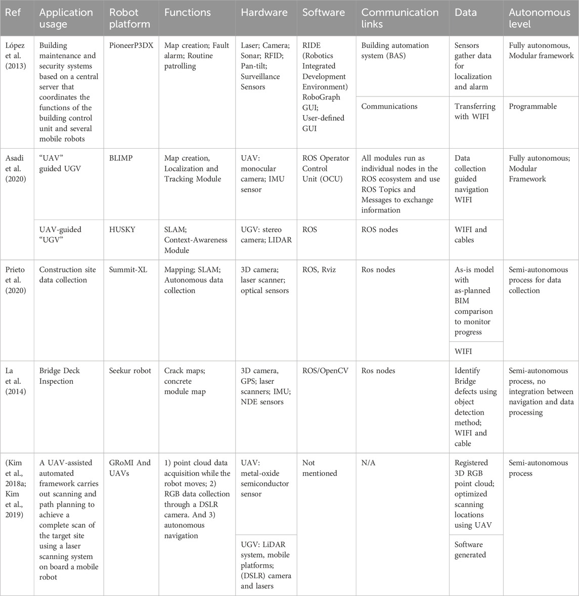
TABLE A1. Overview of construction data collection platforms.
Keywords: semi-autonomous robotic platform, Construction 4.0, robot integration, programmable systems, automation in construction
Citation: Prieto SA, Xu X and García de Soto B (2024) A guide for construction practitioners to integrate robotic systems in their construction applications. Front. Built Environ. 10:1307728. doi: 10.3389/fbuil.2024.1307728
Received: 05 October 2023; Accepted: 23 January 2024;
Published: 08 February 2024.
Edited by:
Shabtai Isaac, Ben-Gurion University of the Negev, IsraelReviewed by:
Venkata Santosh Kumar Delhi, Indian Institute of Technology Bombay, IndiaNatalia E. Lozano-Ramírez, Pontifical Javeriana University, Colombia
Copyright © 2024 Prieto, Xu and García de Soto. This is an open-access article distributed under the terms of the Creative Commons Attribution License (CC BY). The use, distribution or reproduction in other forums is permitted, provided the original author(s) and the copyright owner(s) are credited and that the original publication in this journal is cited, in accordance with accepted academic practice. No use, distribution or reproduction is permitted which does not comply with these terms.
*Correspondence: Samuel A. Prieto, c2FtdWVsLnByaWV0b0BueXUuZWR1