 Pablo Agüero-Barrantes
 Alexandra Hain
- 1Connecticut Transportation Institute, University of Connecticut, Storrs, CT, United States
- 2Department of Civil and Environmental Engineering, University of Connecticut, Storrs, CT, United States
To address the shortcomings of traditional prestressed concrete girders, a new hybrid beam element, the Hybrid Deck Bulb Tee (HDBT) is proposed. The HDBT utilizes staged fabrication. First, the bottom flange is cast with Ultra-high Performance Concrete (UHPC) and prestressed prior to casting the web and top flange with High-Performance Concrete (HPC). The purpose of this study is to analytically evaluate the structural performance of HDBT beams for bridge structures. Multiple HDBT bridges were designed following the state-of-the-art criteria in regard to UHPC bridge design. The performance was evaluated using the following criteria: 1) the deflections under live load and dead load, 2) design checks for temporary stresses before losses, 3) stresses at serviceability limit states after losses, and 4) demand-to-capacity ratios under the American Association of State Highway and Transportation Officials (AASHTO) Strength I load combination. To obtain more refined results for the serviceability limit state, the bridges were modeled using a commercial finite element software. The model captured the time dependent material properties such as strength gain, creep, and shrinkage, as well as the stages of fabrication. The analysis demonstrates that the innovative design and fabrication processes of HDBTs are capable of resolving the current limitations of prestressed concrete elements.
1 Introduction
The American Society of Civil Engineers’ 2021 Report Card for America’s Infrastructure (ASCE, 2021) assigned bridges in the nation a grade of C. The development of innovative solutions in terms of materials, designs, and construction practices are needed to improve the condition and future performance of the bridge inventory in the US. Prestressed concrete beams are one of the most common superstructure materials, making up over 40% of bridges with a span length over 10 m (30 ft) (USDOT, 2023). Despite this prevalence, over the last five decades there have been few advancements in the state-of-the-art for design and construction of prestressed concrete structures. The Decked Bulb Tee (DBT) beam, an option for prestressed concrete superstructures for bridges, has been used since the 1980 s with minimal changes in materials or fabrication (Grace et al., 2015). New trends in concrete structural design includes the use of more durable materials, like Ultra-high Performance Concrete (UHPC) (Binard, 2017; El-Helou and Graybeal, 2019), and new design approaches in order to improve the durability and resilience of new structures, for example, life cycle analysis, robustness analysis, among others (Siqi et al., 2021; Miceli and Castaldo, 2023).
There are four significant issues with the fabrication processes of traditional prestressed concrete girder superstructures. First, the durability of existing prestressed concrete structures when exposed to corrosive environments is well below desired levels as evidenced by the severe level of corrosion observed on in-service bridges (Harrt, et al., 2004; Xue et al., 2020). This poor performance is due to the penetration of moisture and corrosive chemicals into conventional concrete (Nogueira and Leonel, 2013; Okumus et al., 2021). Second, the current fabrication methods for prestressed concrete components generate tension at the endzone as an unintended secondary effect (Ross et al., 2015). These secondary tensile stresses may lead to cracking of the concrete and a reduction in the service life of these components (Torres et al., 2020). Third, the current design method is constrained by the maximum allowable tension in the top fiber of the top flange near both ends (PCI, 2014). In the fabrication of prestressed concrete components, for example, the DBT, the bottom flange benefits from compression by prestressing the bottom flange. Since the point of application of the total prestressing force is eccentric to the center of gravity of the DBT cross section, tension will be developed at the top fiber of the top flange. This tension is a limiting factor on the maximum prestress that can be applied, which may negatively affect the efficiency of the design. Fourth, naturally occurring variations in the camber of prestressed concrete components require significant corrective measures in the field (PCI, 2014). When the prestressing force is applied to concrete beams using traditional fabrication methods, upward deflection, i.e., camber, occurs. This camber can vary significantly from girder to girder even when the fabrication method is similar (Barker and Puckett, 2021). These corrective measures can add cost and time to projects.
While the fabrication and design of concrete elements has remained relatively unchanged, advances in cementitious materials in recent decades have provided opportunities for optimizing both beam design and fabrication procedures, while resolving the current limitations of prestressed concrete bridge beams. One of the most impactful advances in cementitious materials has been the development and expanded use of UHPC. UHPC has many advantages compared to conventional or High-Performance Concrete (HPC) including increased tensile strength, compressive strength over 150 MPa, (21.7 ksi), permeability resistance, and durability (Graybeal, 2011; 2014). The advantages of UHPC for prestressed beams are particularly attractive. For example, the high compressive strength of UHPC enables using smaller bottom flanges, as less material is needed to resist the prestress forces. In addition, UHPC has higher durability than conventional concrete in terms of freeze–thaw degradation resistance, scaling deterioration, chloride penetration, and abrasion resistance (Graybeal and Tanesi, 2007). It also has a low permeability and water absorption capacity which makes the material attractive for use in harsh environments (Abbas et al., 2016). Finally, the high tensile strength and ductility of UHPC reduces the likelihood of cracking the bottom flange, which prevents corrosion of the strands.
Due to the many benefits of UHPC, multiple institutions, including The Federal Highway Administration and the Precast/Prestressed Concrete Institute (PCI), are currently investigating the application of concrete bridge girders made entirely of UHPC (Binard, 2017; El-Helou and Graybeal, 2019). However, full UHPC girders constructed with traditional fabrication steps do not address some issues of prestressed beams, such as unpredictable camber and tension in the top flange. Issues with the uncertainty of camber are noted by Sim et al. (2020) when discussing the design of precast, prestressed UHPC members. They recommended employing unbonded post-tensioned monostrands at the top of the precast concrete girder to enable field adjustments for desired camber (Sim et al., 2020). While this approach is feasible, it adds time and complexity to fabrication and requires difficult geometry control measures during installation, making this unattractive for accelerated construction projects. Currently, the usage of UHPC has been limited due to its significantly higher cost compared to HPC and the lack of formal design guidelines (El-Helou and Graybeal, 2022a). It is anticipated that the increase in cost may limit the adoption of these beams in the near future (Binard, 2017; Graybeal, 2019; Graybeal and El-Helou, 2019).
Another research gap is that the ongoing research on full UHPC prestressed girders or prefabricated superstructures is primarily focused on long-span bridges with noted span lengths of 76.2 m (250 ft) (Sim et al., 2020) or 91.4 m (300 ft) (El-Helou and Graybeal, 2019). While UHPC girders are a promising option for long-span applications, over 95% of girder bridges in the US have spans under 45.7 m (150 ft) (USDOT, 2023). For these bridges, it is important to consider that a superstructure replacement may be an economical alternative to total replacement. In this span range, there are over 40,000 girder bridges with a superstructure rating of 5.0 or below (USDOT, 2023). This means that the superstructure is either considered structurally deficient (4.0 or below) or in fair condition (rating of 5.0). Over 39% of these bridges have substructures that are rated as satisfactory or higher (6.0 or above), which suggests they may be promising candidates for a superstructure replacement in the future. Superstructures using prestressed HPC girders cannot compete with superstructures using steel girders in terms of vertical clearance and dead load. This makes it challenging to replace a steel girder superstructure with prestressed concrete girders, which limits the available options for bridge owners.
To address the shortcomings in the fabrication of traditional prestressed beams and provide a competitive concrete alternative to steel girders in terms of weight and depth, a new hybrid beam element, the Hybrid Deck Bulb Tee (HDBT) was developed. The HDBT utilizes staged fabrication in which the bottom flange is cast with UHPC and prestressed prior to casting the web and top flange with HPC. The HDBT benefits from an optimized design including: 1) using UHPC in critical regions and a common high-performance material for the web and flange to reduce costs, 2) staging the fabrication to control camber and prevent differential camber between units, which eliminates the need for corrective measures in the field, and 3) prestressing only the bottom flange, which avoids the development of tension in the top flange and prevents cracking in the end zone.
To the authors’ knowledge, the research presented in this paper has no precedent publications. Previous research on hybrid approaches using UHPC and normal concrete can be found in Ronanki et al. (2019) and Torres et al. (2020), both in regards of the use of UHPC at the end of girders. Ronanki et al. (2019) presented experimental and analytical results on a long-span hybrid girder concept using UHPC in critical regions along with normal weight concrete. The FEA results show that the proposed element can eliminate the end zone cracking in prestressed girders. Torres et al. (2020) presented a hybrid element composed of conventional self-consolidating concrete between UHPC ends. Both conventional and hybrid Florida-shaped beams were tested to compare the performance under load. Analytical simulations showed that crack widths in conventional beams can be at least 3.75 times greater than the hybrid counterpart. In addition, Hakeem et al. (2022) reported on the experimental testing of rectangular hybrid beams using UHPC as tension reinforcement as an alternative to traditional tension reinforcement. The testing showed that the hybrid-non reinforced element has more moment capacity than conventional non-reinforced members and less moment capacity than normal concrete steel reinforced members.
This paper will summarize the fabrication procedure, describe the preliminary design and critical design checks, and detail a modeling methodology in CSiBridge (CSI, 2019). Additionally, analytical results will be presented to evaluate the structural performance of the proposed HDBT elements. The results showed the HDBT is structurally viable and successful in reducing dead load compared to conventional prestressed concrete designs. It is anticipated that this work will promote future research on hybrid bridge girder elements that may be used to address the current structural deficiencies facing the US bridge network.
2 Methods and materials
2.1 Fabrication of the HDBT element
The first stage of construction consists of forming, casting, and curing the UHPC bottom flange. In this stage, the form is assembled, and the steel reinforcement and strands are placed (Figure 1A). Tension is applied to the strands (Figure 1B) and the UHPC is cast and allowed to cure (Figure 1C). The top surface of the UHPC is roughened to provide a better interface at the joint between the UHPC and HPC in the web. In the second stage, the prestressing strands are released when the UHPC reaches the desired compressive strength, inducing compression in the stand-alone bottom flange. The prestressing does not result in any camber of the bottom flange as the layout of the strands is such that the resultant prestressing force has negligible eccentricity relative to the centroid of the bottom flange.
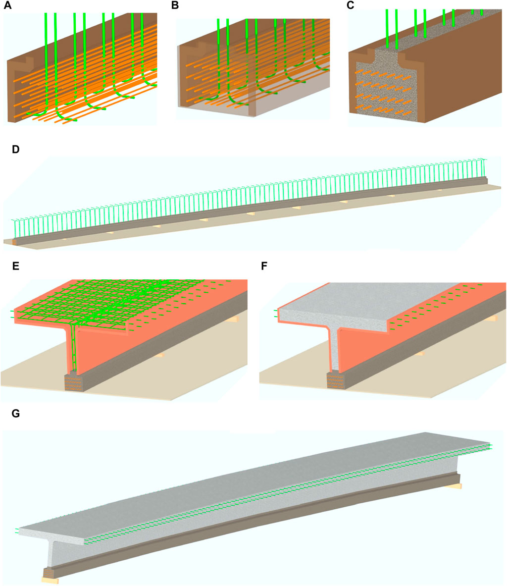
Figure 1. Fabrication stages of the HDBT, (A) placing reinforcement and strands in form, (B) applying tension to strands, and (C) casting and curing UHCP bottom flange, (D) the UHPC bottom flange is shored to set the desired camber, (E) forms are assembled and reinforcement is placed, (F) the web and top flange are cast with HPC, and (G) forms are removed and element is moved to storage.
Thus, to ensure a positive camber, the bottom flange is shored and set to the desired level in Stage 3 (Figure 1D) or the camber can be built into the form. Lateral support may be required to avoid any deflection of the bottom flange as a slender compression element. The fourth stage involves casting the remainder of the element using HPC while the bottom flange is supported. The form is assembled, and the reinforcement is placed (Figure 1E). Once setup is complete, the web and top flange are cast as a single concrete pour (Figure 1F). When the HPC reaches a defined strength, the beam is removed from the forms and stored (Figure 1G).
2.2 Parametric analysis
The following sections summarize the HDBT design considerations.
2.2.1 Bridge geometry and loads
The analyzed bridges serve multiple traffic lines. Four simply supported HDBT girders were spaced at 1.8, 2.5, 3.0, and 3.6 m (6, 8, 10, and 12 ft). It is necessary to note that a 3.6 m-wide (12-ft) member may require a special transportation permit in the US (PCI, 2014). The overhang for exterior beams is 1.07 m (42 in.) Bridge spans reach from 18.3 m to 36.6 m (60–120 ft), which is the typical limit without special transportation requirements in the US (PCI, 2014). The design live load is HL-93 (AASHTO, 2020). A future wearing surface of 75-mm (3-in) thickness bituminous overlay is considered. The long-term wear of the deck is 13 mm (0.5 in). The barrier weighs 7.3 kN/m (0.50 kips/ft) and half of this load is assigned to the exterior girder and the other half to the interior beam. Figure 2 shows a schematic of the HDBT cross section and Table 1 presents the cross-section dimensions for the analyzed spans.
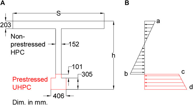
Figure 2. Schematic of HDBT crossing section showing (A) dimensions, and (B) stress distribution for service loads.

Table 1. Cross section dimensions.
These dimensions and loads are included in the PCI Bridge Design Manual (PCI, 2014) due to the quantity of available preliminary designs, based on American Association of State Highway and Transportation Officials Load and Resistance Factor Design (AASHTO LRFD) Specification 2010 (AASHTO, 2010). The comparison with the PCI manual is not included in this research, but the reader should be aware that direct comparison by just material cost is not tantamount. Life Cycle Cost Analysis is recommended for this purpose.
2.2.2 Materials
The material properties of the UHPC in this study were not associated with a specific mix design or proprietary mix. The specified UHPC compressive strength (
2.2.3 Design and limit state criteria
The strand group was modeled with a single tendon element with equivalent area located at the center of gravity of the strand pattern. In the distribution factor calculation, the girders are considered sufficiently connected to act as a unit to apply AASHTO LRFD 4.6.2.2.2. Regarding the serviceability load check, the properties of the transformed section are calculated based on the classical linear theory. The elastic modulus was calculated with equation AASHTO LRFD C5.4.2.4-1, which is recommended for UHPC in El-Helou et al. (2022b). As noted by Ammari and Ahlborn (2023) a good estimation of the modulus of elasticity is instrumental in estimating the total prestress losses. The prestress loss due to elastic shortening of the UHPC bottom flange was calculated according to AASHTO LRFD 5.9.3.2.3 as recommended by Mohebbi and Graybeal (2022). The estimate of time-dependent losses was calculated according to the UHPC proposal of Mohebbi and Graybeal (2022) instead of AASHTO LRFD 5.9.3.4, which underestimates the values of time dependent losses for UHPC. The relative humidity for losses calculations is 70% (H).
Serviceability limit states were checked based on AASHTO LRFD for HPC. Critical to the HDBT design is the tension stress in the HPC-UHPC interface, labelled as point b in Figure 2. The resultant tension stress in the HPC web was compared with the design flexural cracking stress (AASHTO LRFD 5.9.5.4.4c), which is the modulus of rupture (AASHTO LRFD 5.4.2.6) reduced with a 0.85 reduction factor. Regarding UHPC, the compression stress limits included in AASHTO LRFD for conventional concrete can be used for UHPC according to El-Helou and Graybeal (2022a). The effective cracking stress was assumed as 6.7 MPa (1 ksi). The tensile stress limit is taken as a fraction of the stress limit as proposed in El-Helou and Graybeal proposal (2022a), with a reduction factor of 0.85.
Strength checks regarding moment capacity (AASHTO LRFD 5.6.3.2), shear capacity (AASHTO LRFD 5.7.3.3) and interface horizontal shear (AASHTO LRFD 5.7.3.3) were calculated using the HPC design parameters. Regarding the sustained tensile capacity of UHPC participating in the flexural moment capacity, the authors assume that the UHPC bottom flange cannot resist tension stress after the HPC top flange reaches the design compressive strain as described in El-Helou and Graybeal (2022a). In relation to the interface horizontal shear, the authors assume that the HPC properties control the design based on the experimental observations on the failure of hybrid beams fabricated with non-reinforced normal concrete and non-reinforced UHPC, non-reinforced in both cases (Hakeem et al., 2022). Additionally, the experimental study by Semendary and Svecova (2020) concludes that the AASHTO LRFD design parameters are conservative and can be used in the design of UHPC connections.
Deflection control was calculated based on ASSHTO LRFD 3.6.1.3.2 and AASHTO LRFD 2.5.2.6.2. The contribution of the parapets to the stiffness of the superstructure is not considered in the preliminary design. While the criterion for deflection is optional, the authors include deflection in the analysis for reference purposes.
2.2.4 Iterative design criteria
The HDBT design starts with the dimensions and the minimum specified values for concrete materials. The initial number of 0.6-in strands is two. The code iterates the design limit states in the following order: serviceability-temporary stress before losses for the bottom flange; serviceability limit state for the HDBT full section; ultimate strength limit state for bending moment, shear, and horizontal shear for the UHPC-HPC interface. Live load deflection is included in the checks. Every noncompliance leads to increase the HPC strength, the UHPC strength, or the strand number as required. The process is terminated when the design is compliant, or the maximum number of iterations is reached.
2.3 Refined analytical model
To extend the Live Load distribution factor design approach, a refined analysis is presented as an additional tool. Three single span bridges with 24.4 m, 30.5 m, and 36.6 m (80 ft, 100 ft, and 120 ft) were modeled, with HDBT56, HDBT63, and HDBT72 sections, respectively. In all three cases, a 2.4 m (8-ft) girder spacing was used. UHPC’s
The commercial software CSiBridge (CSI, 2019) was used for the analysis of a simple span bridge with a HDBT superstructure. As other software may be used, the general modelling procedure will be outlined, but specific features of CSiBridge will not be discussed. The analysis included all phases of the staged fabrication to capture stress accumulation and strain compatibility between stages. The model captures composite action under permanent loads acting on the long-term composite section, the wearing surface load, and HL-93 vehicular live load as defined by AASHTO LRFD (AASHTO, 2018). The authors note that any numerical model is always affected by epistemic uncertainties (Miceli and Castaldo, 2023). Epistemic uncertainty analysis (Gino et al., 2021) is not part of this work but is anticipated in future research.
2.3.1 Finite element model assembly
The UHPC bottom flange was modeled with frame elements and included the prestressing strand group that was modeled with a single tendon element with an equivalent area located at the center of gravity of the strand pattern. The HPC web and top flange were modeled with shell elements. In determining the optimal mesh size for the structural model, a critical balance was sought between computational efficiency and the fidelity of the simulation results. An iterative approach was utilized, starting with a coarse mesh, and progressively refining it until the results exhibited minimal variation with further mesh refinement. Element thicknesses were set at 152 mm (6 in) for the web and 203 mm (8 in) for the deck. The mesh size varied between 0.38 and 0.56 m (15 and 22 in). The support conditions were defined as a pin-roller condition. The wearing surface and parapets are defined as area loads and line loads, respectively. The contribution of the parapets to the stiffness of the superstructure was not considered in the model. The reinforcement steel in the web and the deck was not explicitly modeled, i.e., confinement effects are not accounted for in this model. A view of the overall model is shown in Figure 3.
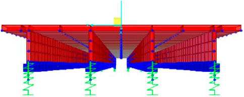
Figure 3. 3-D view of model from analysis showing a single span four-beam bridge with HDBT elements.
2.3.2 Time dependent properties of the materials
The creep and shrinkage coefficients for UHPC were obtained from the Swiss standard, based on the approach used by Jain and Sritharan (2019) for the design of long-span UHPC double tees for building structures. The compressive strength and stiffness were modified based on the strength gain equation presented by Russell and Graybeal (2013). In addition to the time-dependent properties, nonlinear material data was used in section designer to calculate the moment capacity of the section. The nonlinear material data is based on El-Helou and Graybeal including compressive and tensile parameters (2019).
For the HPC, the creep, shrinkage, and compressive strength and stiffness parameters were calculated according to CEB/FIP-90 (CEB, 1990). The nonlinear material data used in the section designer to calculate the moment capacity of the section was from Jiratatprasot (2002). Non-linear and time-dependent properties for both the UHPC and HPC were considered in the serviceability limit state for stress, deformation, and displacement calculations. Staged construction analysis was performed as described in the next section. Including non-linear and time dependent properties in the analytical model was critical to capture the effects of staged fabrication sequencing on the overall strength of the section as well as stress accumulation and strain compatibility between stages.
2.3.3 Sequencing of staged fabrication
Multi-step load cases with time-dependent material properties were used to define the different stages of the fabrication process. The fabrication process and corresponding modeling steps are shown in Figure 4. This modeling process begins with adding the UHPC bottom flange, which represented casting the UHPC. In the model, prestress was added once the UHPC reached a strength of 100 MPa (14 ksi). After prestress is applied, losses in the UHPC accumulate. The model accounts for 3 days before the HPC is cast to allow for prestress losses in the bottom flange to accrue. The time between prestressing and casting the HPC can be easily modified based on the anticipated casting schedule. After the HPC is cast and reaches 50 MPa (7 ksi), the complete self-weight of the beam is added. This corresponds to when the beam can be lifted off the shoring and moved around the site. When the HPC reaches 70 MPa (10 ksi), the load patterns for the barrier and wearing surface are added. Different staged fabrication cases were defined for the Strength I and serviceability limit states. These incorporate the relevant dead load factors for dead load of structural components and non-structural attachments (DC), and dead load of wearing surfaces and utilities (DW) defined in AASHTO LRFD Tables 3.4.1-1 and 3.4.1-2 (AASHTO, 2020). At the end of each staged fabrication case, the live load is applied to the structure using a moving load case. The corresponding live load factors for each case from AASHTO LRFD Tables 3.4.1-1 and 3.4.1-4 (AASHTO, 2020) are incorporated in the design load combinations.
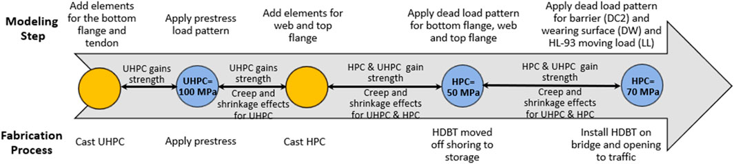
Figure 4. Schematic showing the fabrication steps and corresponding modeling steps in the analysis.
3 Results
3.1 Sectional analysis results
Figures 5–7 show the sensitivity analysis for HDBT72, HDBT63, and HDBT54 sections respectively. The analysis includes span length, girder spacing, UHPC strength, HPC strength and number of strands. Spans less than 25.9 m (85 ft) do not require UHPC strengths above the minimum specified 124 MPa (18 ksi). On the other hand, HPC elements require
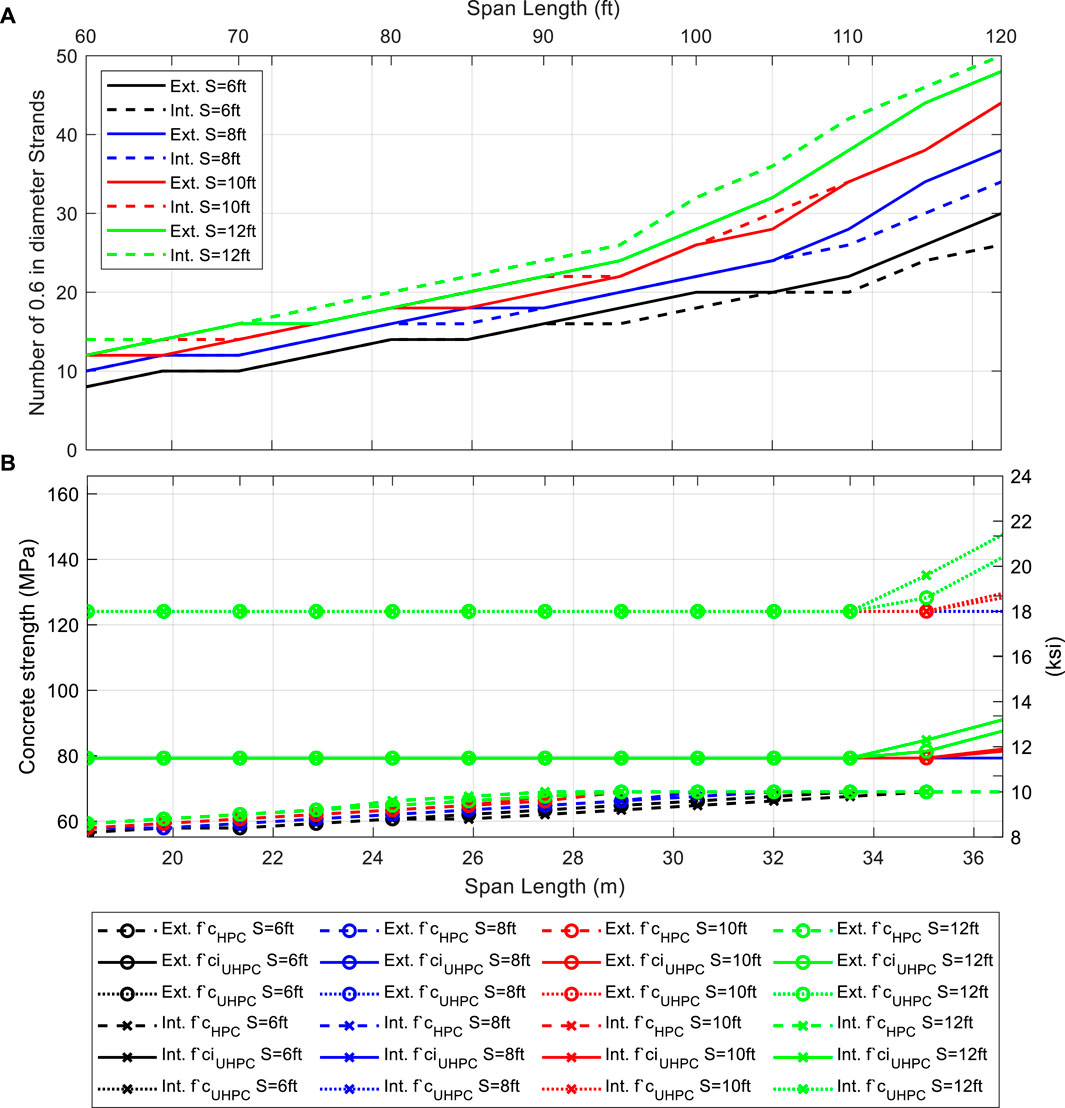
Figure 5. HDBT72 sensitivity analysis as a function of bridge span, girder spacing, and girder location (external or internal); (A) number of required 0.6-in stands; (B) required HPC’s compressive strength, required UHPC’s compressive strength at strain release, and required UHPC’s compressive strength.
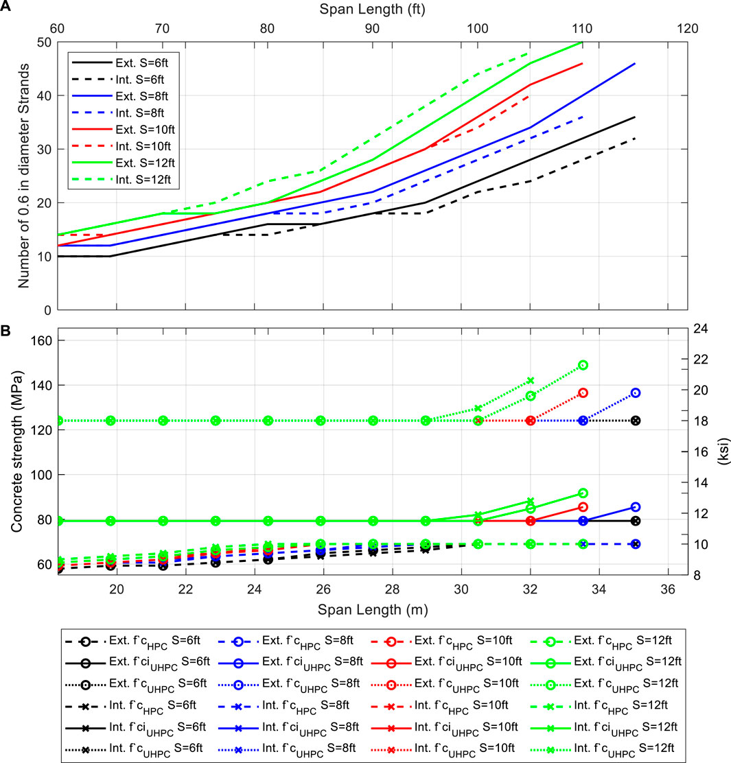
Figure 6. HDBT63 sensitivity analysis as a function of bridge span, girder spacing, and girder location (external or internal); (A) number of required 0.6-in stands; (B) required HPC’s compressive strength, required UHPC’s compressive strength at strain release, and required UHPC’s compressive strength.
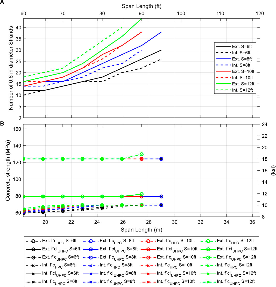
Figure 7. HDBT54 sensitivity analysis as a function of bridge span, girder spacing, and girder location (external or internal); (A) number of required 0.6-in stands; (B) required HPC’s compressive strength, required UHPC’s compressive strength at strain release, and required UHPC’s compressive strength.
The design standards require UHPC strength values up to 149 MPa (21.6 ksi) for spans greater than 33.5 m (110 ft), 28.9 m (95 ft), and 25.9 m (85 ft) for HDBT72, HDBT63, and HDBT54, respectively. Strand requirements vary from 24 to 50 for HDBT72, 22 to 50 for HDBT63 and 22 to 44 for HDBT54.
In general, increasing the maximum HPC strength limit, defined as 10 ksi (70 MPa) in Figures 5–7 results, does not improve the strand number results significantly, i.e., more than two strand reduction. AASHTO LRFD includes conventional concrete design specifications for compressive strengths up to 103 MPa (15 ksi). Even though the strand number is seldom affected, rising HPC
Increasing UHPC strength reduces the strand requirement. For example, Figure 8 shows the strand number reduction using
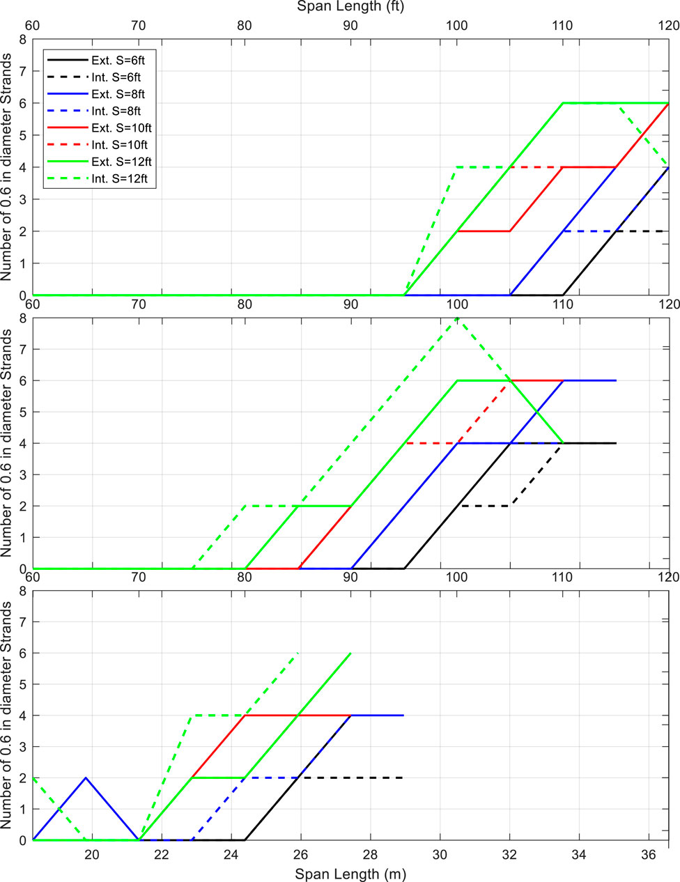
Figure 8. Strand number reduction using
The HDBT design is ruled by the serviceability limit state. Figure 2 shows the HDBT stress distribution for the serviceability limit state. The section experiences compressive stress at the non-prestressed HPC deck and at the prestressed UHPC bottom flange. The non-prestressed HPC web experiences a combination of compressive and tensile stress, below the neutral axis. The maximum tensile stress at service in the HPC web occurs in point b in Figure 2. In all cases the tensile stress values are above the limit for cracking. This cracking can be controlled adding reinforcement as described in AASTHO LRFD 5.6.7. The previously mentioned FE analysis allows for additional study of the web region. The results will be presented in the next section.
3.2 FEM results
Given that the preliminary design is satisfactory in terms of ultimate limit state for flexure and shear, live load deflection control, and serviceability limit state for compressive stress at transfer, the FEM analysis results are focused on the serviceability load combination stress. In the preliminary design, the stress from the serviceability limit state exceeded the capacity of the section, thus requiring further analysis.
Figure 9 shows the results of the HPC web tensile stress from the Finite Element Analysis considering the stiffness off all bridge girders distributing the vehicular load. The reduction in the stress value is 21%, 24%, and 26% for 24.4 m, 20.5 m, and 36.6 m (80 ft, 100 ft, and 120 ft) cases respectively. Although differences exceeding 20% often raise concerns about the validity of a modeling approach, it is essential to acknowledge that the sectional analyses noted may overlook certain complexities. Upon conducting basic model verifications that disregarded staged construction effects, our team gained assurance in the model’s ability to accurately represent the behavior of the HDBT. However, the nuanced behavior stemming from staged construction can only be captured in the analytical evolution. This includes how time dependent properties impact stress transfer, which, in turn, enables a more precise prediction of deformations and stresses under service load conditions.
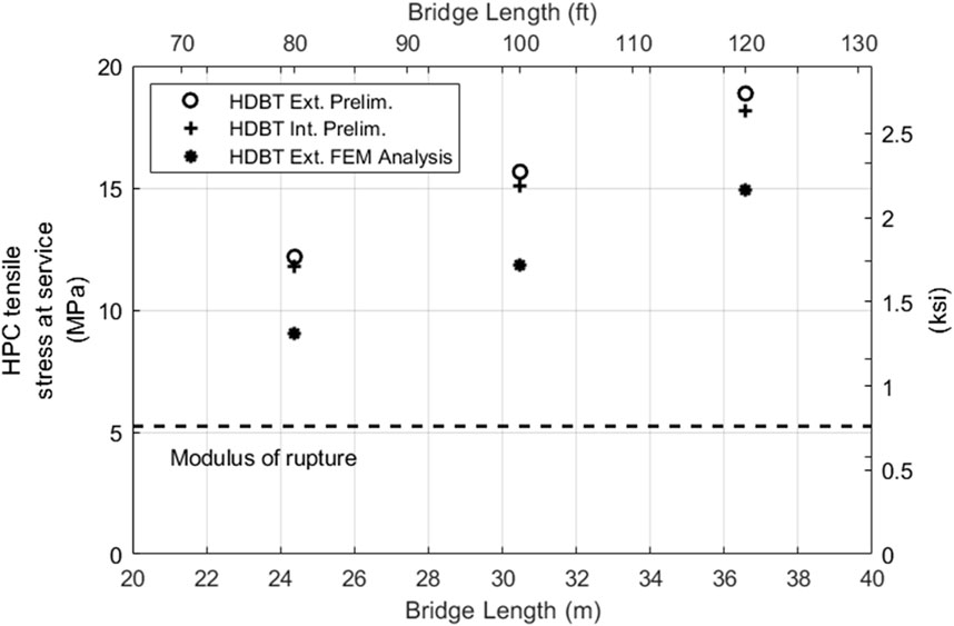
Figure 9. HPC tensile stress at service for preliminary design and FEM analysis.
Figure 10 shows the side view of the 36.6-m (120-ft) long HDBT beam and the theoretical location of cracking limits (i.e., where the tensile stress equals the tensile serviceability limit for HPC) for the following load cases: self-weight, dead load, staged construction, FEM analysis Service I, and preliminary design Service I combinations. Below the limit, cracking is expected for the corresponding load case. As mentioned earlier these results provide the information for the areas where distributed reinforcement based on AASTHO LRFD 5.6.7 should be placed for cracking control, if required. In the presented analysis case, where the flexure moment is resisted by the pretension reinforcement, horizontal reinforcement for cracking control with a spacing of 800, 1,000 and 1,300 mm (31, 40, and 52 in) should be provided. This spacing requirement can be easily fulfilled providing horizontal reinforcement to the HPC web. The previous calculation was made considering a layer of horizontal reinforcement located 50 mm (2 in) above the UHPC/UPC interface and an exposure factor of 0.75.
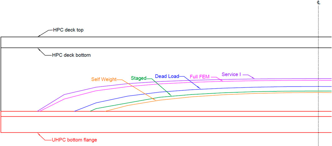
Figure 10. Schematic showing the side view of one-half of the 36.6 m-long (120 ft) HDBT72 beam with the line-limit which cracking is expected below the limit for different load cases: preliminary design Service I load combination (Service I), full Finite Element Analysis (FEM), FEM staged construction analysis (Staged), dead load, and self-weight. Vertical to horizontal scale 2:1.
4 Discussion of results
In this research, multiple design parameters have been varied, encompassing span length, girder spacing, the compressive strength of UHPC and HPC strength, and the quantity of prestressing strands. The findings show that increasing HPC strength leads to increasing the capacity of the web, which can limit the required shear reinforcement and crack control reinforcement, streamlining the design requirements. Furthermore, the influence of the UHPC bottom flange strength on strand quantity is significant. A higher UHPC strength facilitates a reduction in the number of prestressing strands necessary to achieve the desired structural performance as demonstrated in Figure 8. Table 2 summarizes the results discussed previously, where four scenarios are included. The first includes the span ranges where the HDBT can be designed using minimum values of HPC strength. The second scenario considers higher strengths of HPC. As discussed previously the HPC specified strength does not severely impact the serviceability and ultimate limit states. For all analysed span lengths, increasing HPC compressive strength can reduce the required strands by a maximum of two strands. The third and fourth scenarios account for higher UHPC strength, where the number of strands can be reduced in longer spans. Strand reduction was split in up to two and four to eight strand reduction. The first scenario would be ideal for shorter span bridges and the fourth one is suitable for longer span bridges.
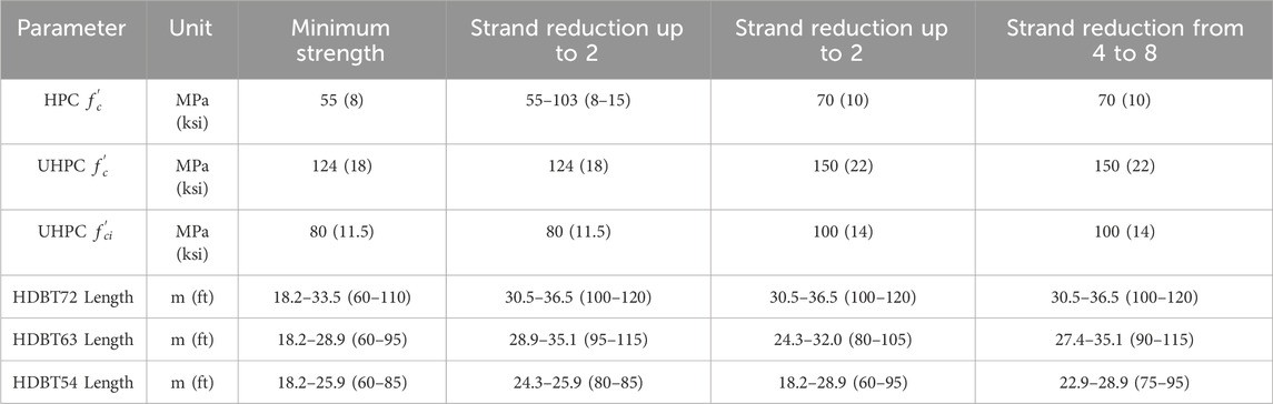
Table 2. Span range scenario summary.
The results for the spans included in this study demonstrated that the system can be designed to meet the required performance criteria. The results show that there are multiple ways of improving the Ultimate and Serviceability capacities by increasing the height of the section, adding strands, modifying the dimensions of the cross section, and setting performance criteria for the materials to obtain desired results. This may include selecting a specific UHPC material for the bottom flange to achieve certain strengths or creep and shrinkage characteristics. Another option is using light weight HPC for web and deck, reducing the self-weight of the beam. The staged fabrication also allows for the specialized design of elements for specific site considerations. As the web and top flange are not prestressed, the forms can be modified for different geometries, such as casting elements for skewed bridges or using a variable web height to provide a sag condition at the top of the element while maintaining a positive camber.
As noted above, the design of HDBT elements can be easily optimized for site-specific needs. The unique fabrication sequencing and use of UHPC and HPC allows the HDBT element to compete with steel girders in terms of total depth and weight where traditional prestressed beams could not. The flexibility of the design along with the inherent benefits of using high-performance materials makes the HDBT a promising option for both superstructure replacement projects and new construction.
FEM allows for more refined analysis when required, The effectiveness of the FE model to capture the structural behavior was proven as a tool to perform a best estimation of the web-cracking. In regards of potential web cracking, owners can specify a level of acceptance for web cracking which is reflected in the exposure factor of AASTHO LRFD 5.6.7.
5 Conclusion
This research was conducted to show the structural viability of the proposed HDBT system. The preliminary design was performed using sectional analysis based on strain compatibility and force equilibrium. The design parameters were based on state-of-the-art research results. The study includes a method for analyzing a simple-span bridge with HDBT elements using CSiBridge or a similar modeling software. The approach considers all phases of the stage fabrication to capture stress accumulation and strain compatibility between stages. The major findings include:
• In the HDBT analysis, the camber was controlled, and no tension was developed in the top flange from prestressing the stand-alone bottom flange. This demonstrates that the innovative design and fabrication process of HDBTs can resolve the current limitations of prestressed concrete elements.
• The cross sections analyzed passed the design checks required for prestressed concrete girders. In the web where there is tensile stress in the HPC, the issue can be addressed with distributed passive steel for crack control. In special cases, the surface of the web can be weather treated if the bridge’s owner requires. This shows the HDBT is a feasible alternative to currently available steel and prestressed concrete girders.
• The modeling approach can be easily modified to study different cross sections, material-specific performance, permitted loadings, and effect of loading components at different times.
Future research should focus on two primary objectives. Firstly, a Life Cycle Cost Analysis (LCCA) to assess the cost-effectiveness of the Hybrid Bridge Deck Technology (HBDT) in comparison to conventional bridge designs. Secondly, laboratory tests on an HBDT sample are crucial to corroborate the findings of this study. Building on this, it is essential to refine a Finite Element Model (FEM) of the HBDT incorporating epistemic uncertainty analysis as suggested by Gino et al. (2021), ensuring the model’s accuracy and reliability.
Data availability statement
The raw data supporting the conclusion of this article will be made available by the authors, without undue reservation.
Author contributions
PA-B: Formal Analysis, Investigation, Methodology, Software, Visualization, Writing–original draft. AH: Conceptualization, Funding acquisition, Methodology, Project administration, Supervision, Visualization, Writing–review and editing.
Funding
The author(s) declare that financial support was received for the research, authorship, and/or publication of this article. This analysis was funded through a research project titled “Proof of Concept Evaluation of Hybrid Deck Bulb Tee (HDBT).” Funding was provided by Advanced Bridge Construction Technologies.
Acknowledgments
The guidance of Dr. Arash E. Zaghi and Mathew Royce during the project is noted. PA-B acknowledges the support provided by the University of Costa Rica and LanammeUCR for supporting his doctoral studies.
Conflict of interest
The authors declare that the research was conducted in the absence of any commercial or financial relationships that could be construed as a potential conflict of interest.
Publisher’s note
All claims expressed in this article are solely those of the authors and do not necessarily represent those of their affiliated organizations, or those of the publisher, the editors and the reviewers. Any product that may be evaluated in this article, or claim that may be made by its manufacturer, is not guaranteed or endorsed by the publisher.
References
AASHTO (2010). AASHTO LRFD bridge design specifications. Washington D.C.: American Association of State Highway and Transportation Officials. ISBN: 978-1-56051-451-0.
AASHTO (2018). The manual for bridge evaluation. Washington D.C.: American Association of State Highway and Transportation Officials. ISBN: 978-1-56051-683-5.
AASHTO (2020). AASHTO LRFD bridge design specifications. Washington D.C.: American Association of State Highway and Transportation Officials. ISBN: 978-1-56051-738-2.
Abbas, S., Nehdi, M. L., and Saleem, M. A. (2016). Ultra-high performance concrete: mechanical performance, durability, sustainability, and implementation challenges. Int. J. Concr. Struct. Mater. 10 (3), 271–295. doi:10.1007/s40069-016-0157-4
Ammari, M., and Ahlborn, T. M. (2023). Overview of the prestress losses and long-term deflection response of ultra-high performance concrete members. Int. Interact. Symposium Ultra-High Perform. Concr. 3 (1), 128. doi:10.21838/uhpc.16731
ASCE (2021). A comprehensive assessment of America’s infrastructure: 2021 repost card for America’s infrastructure. Available at: www.infrastructurereportcard.org.
Barker, R. M., and Puckett, J. A. (2021). Design of Highway bridges: an LRFD approach. New Jersey: John Wiley and Sons, Inc., ISBN: 978-1-119-64631-0.
Binard, J. (2017). UHPC: a game-changing material for PCI bridge producers. PCI J. 62 (2), 34–46. doi:10.15554/pcij62.2-01
CEB (1990). CEB-FIP model code 1990. Bull. D’Information No. 213/214. Com. Euro-International Du. Beton. ISBN: 978-0-7277-1696-5. doi:10.1680/ceb-fipmc1990.35430.fm
CSI (2019). CSiBridge v22 [Computer software]. Available at: https://www.csiamerica.com/.
El-Helou, R. G., and Graybeal, B. A. (2019). “The ultra girder: a design concept for a 300-foot single span prestressed ultra-high performance concrete bridge girder,” in Proc. 2nd International Interactive Symposium on Ultra-High Performance Concrete., Ames, IA, June, 2019. doi:10.21838/uhpc.9707
El-Helou, R. G., and Graybeal, B. A. (2022a). Flexural behavior and design of ultrahigh-performance concrete beams. J. Struct. Eng. 148 (4), 04022013. doi:10.1061/(ASCE)ST.1943-541X.0003246
El-Helou, R. G., Haber, Z. B., and Graybeal, B. A. (2022b). Mechanical behavior and design properties of ultra-high performance concrete. ACI Mater. J. 119 (1). doi:10.14359/51734194
Gino, D., Castaldo, P., Giordano, L., and Mancini, G. (2021). Model uncertainty in non-linear numerical analyses of slender reinforced concrete members. Struct. Concr. 22 (2), 845–870. doi:10.1002/suco.202000600
Grace, N. F., Bebawy, M., and Kasabasic, M. (2015). “Evaluation and analysis of decked bulb T beam bridges,” in Transportation pooled fund program, federal project number: tpf-5(254) (Southfield, MI, USA: Lawrence Technological University. Dept. of Civil Engineering).
Graybeal, B. A. (2011). “Ultra-High performance concrete”. FHWA publication No.: fhwa-HRT-11-038. Washington, DC: Federal Highway Administration.
Graybeal, B. A. (2014). “Design and construction of field-cast UHPC connections”. FHWA publication No.: FHWA-HRT-14-084. United states department of transportation. Washington, DC: Federal Highway Administration.
Graybeal, B. A. (2019). “Advancing ultra-high performance concrete in the bridge sector,” in 2019 International Accelerated Bridge Construction Conference: Including Automation, Service Life and Ultra High Performance Concrete (UHPC), Miami, Florida, December, 2019. Accelerated Bridge Construction University Transportation Center, Civil and Environmental Engineering Department at Florida International University.
Graybeal, B. A., and El-Helou, R. G. (2019). Development of an AASHTO guide specification for UHPC. Int. Interact. Symposium Ultra-High Perform. Concr. 2 (1). doi:10.21838/uhpc.9708
Graybeal, B. A., and Tanesi, J. (2007). Durability of an ultrahigh-performance concrete. J. Mater. Civ. Eng. 19 (10), 848–854. doi:10.1061/(ASCE)0899-1561(2007)19:10(848)
Hakeem, I. Y., Rahman, M. K., and Althoey, F. (2022). Experimental investigation of hybrid beams utilizing ultra-high performance concrete (UHPC) as tension reinforcement. Materials 15, 5619. doi:10.3390/ma15165619
Harrt, W. H., Powers, R. G., Leroux, V., and Lysogorski, D. K. (2004). A critical literature review of high-performance corrosion reinforcements in concrete bridge applications. Final Report FHWA-HRT-04-093. Washington, DC: Office of Infrastructure Research and Development Federal Highway Administration. Available at: https://rosap.ntl.bts.gov/view/dot/39307.
Jain, S., and Sritharan, S. (2019). “Long span UHPC double tees for building structures–A design process,” in Proc. International interactive symposium on ultra-high performance concrete (Ames, Iowa, United States: Iowa State University Digital Press). doi:10.21838/uhpc.9660
Jiratatprasot, P. (2002). Mechanical properties and stress-strain behavior of high performance concrete under uniaxial compression. Available at: https://digitalcommons.njit.edu/theses/674.
Miceli, E., and Castaldo, P. (2023). Robustness improvements for 2D reinforced concrete moment resisting frames: parametric study by means of NLFE analyses. Struct. Concr. 2023, 9–31. doi:10.1002/suco.202300443
Mohebbi, A., and Graybeal, B. (2022). Prestress loss model for ultra-high performance concrete. Eng. Struct. 252 (2022), 113645. doi:10.1016/j.engstruct.2021.113645
Nogueira, C. G., and Leonel, E. D. (2013). Probabilistic models applied to safety assessment of reinforced concrete structures subjected to chloride ingress. Eng. Fail. Anal. 31 (2013), 76–89. doi:10.1016/j.engfailanal.2013.01.023
Okumus, P., Oliva, M. G., and Becker, S. (2021). Nonlinear finite element modeling of cracking at ends of pretensioned bridge girders. Eng. Struct. 40 (2012), 267–275. doi:10.1016/j.engstruct.2012.02.033
Ronanki, V. S., Aaleti, S., and Binard, J. P. (2019). Long-span hybrid precast concrete bridge girder using ultra-high-performance concrete and normal weight concrete. PCI J. 64 (6). doi:10.15554/pcij64.6-02
Ross, B. E., Hamilton, H. R., and Consolazio, G. R. (2015). Experimental study of end region detailing and shear behavior of concrete I-girders. J. Bridge Eng. 20. doi:10.1061/(ASCE)BE.1943-5592.0000676
Russell, H. G., and Graybeal, B. A. (2013). Ultra-high performance concrete: a state-of-the-art report for the bridge community. Washington, DC: United States Department of Transportation, Federal Highway Administration. Office of Infrastructure. Publication No. FHWA-HRT-13060.
Semendary, A. A., and Svecova, D. (2020). Interfacial parameters for bridge connections at high-strength concrete–ultrahigh-performance concrete interface. J. Mater. Civ. Eng. 32 (4), 04020060. doi:10.1061/(ASCE)MT.1943-5533.0003107
Semendary, A. A., and Svecova, D. (2021). Bond characterization and interfacial coefficients at precast UHPC and cast-in-place UHPC interface. J. Mater. Civ. Eng. 33 (7), 04021143. doi:10.1061/(ASCE)MT.1943-5533.0003755
Sim, C., Tadros, M., Gee, D., and Asaad, M. (2020). Flexural design of precast, prestressed ultra-high-performance concrete members. PCI J. 65 (6), 35–61. doi:10.15554/pcij65.6-02
Siqi, W., Liye, Z., Han, S., and Junsheng, D. (2021). Time-dependent robustness-based condition assessment of RC bridges subjected to corrosion. Structures 34, 4500–4510. doi:10.1016/j.istruc.2021.10.061
Torres, E., Hamilton, H. R., and Consolazio, G. R. (2020). Hybrid prestressed concrete bridge girders using ultra-high performance concrete. FDOT Contract No. BDV31-977-101. Gainesville, FL, United States: University of Florida UF Project No P0086443 and P0086444 Sponsor: Florida Department of Transportation FDOT.
USDOT (2023). “LTBP InfoBridge - data”. United states department of transportation. Available at: https://infobridge.fhwa.dot.gov/Data.
Keywords: ultra-high-performance concrete, bridge rehabilitation, composite elements, precast beam, superstructure replacement, Decked Bulb Tee, finite element analysis
Citation: Agüero-Barrantes P and Hain A (2024) Numerical evaluation of Hybrid Deck Bulb Tee (HDBT) as a solution to improve durability of single-span bridges. Front. Built Environ. 10:1280978. doi: 10.3389/fbuil.2024.1280978
Received: 21 August 2023; Accepted: 08 April 2024;
Published: 01 May 2024.
Edited by:
Franck Schoefs, Université de Nantes, FranceReviewed by:
Jun He, Changsha University of Science and Technology, ChinaPaolo Castaldo, Polytechnic University of Turin, Italy
Bernt Johan Leira, NTNU Technology Transfer, Norway
Copyright © 2024 Agüero-Barrantes and Hain. This is an open-access article distributed under the terms of the Creative Commons Attribution License (CC BY). The use, distribution or reproduction in other forums is permitted, provided the original author(s) and the copyright owner(s) are credited and that the original publication in this journal is cited, in accordance with accepted academic practice. No use, distribution or reproduction is permitted which does not comply with these terms.
*Correspondence: Alexandra Hain, YWxleGFuZHJhLmhhaW5AdWNvbm4uZWR1