 Matteo Marra
 Michele Palermo
 Stefano Silvestri
- Department of Civil, Chemical, Environmental, and Materials Engineering - DICAM, University of Bologna, Bologna, Italy
This paper introduces an updated formulation of a five-step procedure dealing with the design of fluid viscous dampers for the seismic retrofitting of existing frame buildings. The original design procedure is known as the “direct five-step procedure,” and is articulated into 5 consecutive steps guiding the designer from the identification of the expected seismic performances, to the sizing of the added viscous dampers up to the final verification of the seismic behavior through non-linear dynamic time history analyses. The procedure leads to the full definition of the mechanical characteristics of the commercial non-linear viscous dampers and allows to estimate the maximum dissipative forces acting in the dampers and the internal forces in the frame members. The objective of the design procedure, when applied to a new building, is to size the dampers in order to keep the structural elements within the linear elastic range considering a “rare” earthquake design level. However, when dealing with an existing building, especially if originally designed considering vertical loads only, the insertion of viscous dampers could be not sufficient to keep the structural elements in the elastic range. Thus, it might be necessary to accept local plastic excursion of the structural elements, by taking into account the ductility capacity (albeit probably limited) of the structural members (hysteretic dissipation associated with damage in beams and columns). This latter aspect is explicitly considered in the updated formulation of the “direct five-step procedure” presented here through the introduction of an overall response reduction factor accounting for both the ductility capacity of the structural members and the viscous damping provided by the added dampers. The design procedure is then applied to a 11-storey frame structure case study, which is representative of reinforced concrete buildings designed for vertical loads only. Three different retrofitting design strategies are considered, based on different exploitation of viscous energy dissipation provided by the dampers and hysteretic energy dissipation due to the excursion of the structural members into the inelastic regime.
1 Introduction
Energy dissipation represents a consolidated concept for the mitigation of the seismic effects in building structures (Constantinou et al., 1993; Foti et al., 1998; Christopoulos and Filiatrault, 2006; Liang et al., 2011; Foti, 2014a; Foti, 2014b). Among all possible types of seismic dissipators, fluid viscous dampers have widely proven to be effective in seismic protection of frame structures. However, their application is still limited. This is also due lack of specific code prescriptions and simple design procedures. For instance, the Italian building code (NTC, 2018) does not provide explicit indications for the design of buildings equipped with viscous dampers, while specific design procedures and indications are given for seismic isolation devices.
The applicative guidelines of the Italian building code (hereafter referred to as Circular (C.S.LL.PP. Consiglio Superiore dei Lavori Pubblici, 2019)) distinguish between velocity-dependent dissipation devices and displacement-dependent devices, underlining their common goal of reducing deformations to contain damage and avoid collapse of the structure, and highlighting the importance of a seismic vulnerability analysis for an existing building to be strengthened. Nevertheless, the Circular does not suggest neither pre-dimensioning/design formulas for the different types of dampers, nor practical indications regarding how the ductile capacities of the existing structure could be taken into account.
In the last decades several design procedures for frame buildings equipped with viscous dampers were proposed in the literature (Constantinou et al., 1993; Green, 1987; Constantinou and Symans, 1992; Takewaki, 1997; Pekcan et al., 1999; Shea, 1999; Shukla and Datta, 1999; Takewaki, 2000; Garcia, 2001; Ramirez, 2001; Rami et al., 2002; Singh and Moreschi, 2002; Manual, 2003; Ramirez et al., 2003; Whi et al., 2003; Kasai and Kibayashi, 2004; Levy and Lavan, 2006; Takewaki, 2011; Weng et al., 2012; Landi et al., 2014), including the “five-step procedure” (Trombetti and Silvestri, 2004; Trombetti and Silvestri, 2006; Silvestri et al., 2010; Palermo et al., 2013a; Palermo et al., 2013b; Palermo et al., 2015; Trombetti et al., 2015; Palermo et al., 2017a) and the “direct five-step procedure” (Palermo et al., 2016; Palermo et al., 2017b; Palermo et al., 2018) developed by some of the authors. This latter design procedure consists of 5 consecutive steps and is based on the identification of a target seismic performance to be achieved, such as a target damping ratio. The preliminary design of the dampers and the assessment of the seismic performances of the frame structure is fully developed with analytical formulas, while the final verification of the seismic behavior need to be conducted through non-linear dynamic time-history analyses. The procedure aims at defining the main mechanical characteristics of the commercial fluid viscous dampers which are typically governed by a non-linear force-velocity relationship (
In the case of new frame buildings, the main design principle is to keep the structural elements within the linear elastic range for a “rare” earthquake design level. Nevertheless, in the case of existing frame buildings designed for vertical loads only, the introduction of a damper system could be not sufficient to keep the structural elements in the elastic range. Therefore, it might be necessary to accept local plastic excursion of the structural elements, by taking into account the limited ductility capacity of the structural members and the associated hysteretic dissipation resulting from structural damage. The paper proposes a new formulation of the “direct five-step procedure” specifically targeted to existing buildings which accounts for the ductility capacity of the structural members. This new formulation is introduced in Section 2 and then applied in Sections 3 and 4 to a 11-storey Reinforced Concrete (RC) case study building.
The rationale behind the method is general and independent from the specific code while its implementation for practical design requires the reference to a specific building code. Therefore, the current manuscript has been written with reference to the Italian code (NTC, 2018).
2 The “direct five-step procedure” tailored for existing buildings
2.1 Overview of the “direct five-step procedure”
The original “direct five-step procedure” for the design of frame structures equipped with fluid-viscous dampers was proposed by some of the authors (Palermo et al., 2018). The procedure applies to yielding frame structures with a generic along-the-height distribution of inter-storey viscous dampers. It is aimed at guiding the designer through the sizing and verification of both viscous dampers and structural elements.
The design procedure is based on 5 consecutive steps. In STEP 1 the expected seismic performance objectives are identified leading to the evaluation of the total response reduction factor accounting for both the ductility demand and the viscous damping provided by the added dampers, as detailed in Section 2.2. Then, in STEP 2, the linear damping coefficients of the added viscous dampers are computed in order to reduce the structural response according to the selected target damping ratio. Analytical formulas are employed in STEP 3 to estimate the design values of the peak velocities and dissipation forces in the dissipative devices, while an energy criterion is used in STEP 4 to identify the equivalent non-linear damping coefficient of the actual manufactured viscous dampers. Finally, in STEP 5, the internal forces in the structural elements can be estimated through the envelope of two Equivalent Static Analyses (ESA). Non-linear dynamic time history analyses are then carried out to conduct the final verifications.
In particular, for the specific case of inter-storey placement of viscous dampers of equal size, the following direct formulas can be used to estimate both the required damping coefficient and the minimum axial stiffness (fluid + support component) of the commercial non-linear dampers:
For existing buildings, the insertion of dampers reduces the deformations and internal forces in the structural elements, and, in the case of structural response beyond the elastic limit, the ductility demand. In the latter case, the available ductility capacity (although probably limited) can be properly considered in the design phase, especially when dealing with old existing buildings designed for vertical loads only (often characterized by reduced seismic capacities). Therefore, in these cases, it might be necessary to partially account for a portion of the available ductility, when designing the added fluid viscous dampers.
In this regard, it is worth pointing out that, in order to consider the coupling of the hysteretic damping provided by the structural elements with the viscous damping provided by the dampers, non-linear dynamic analyses have to be carried out as also recommended by technical codes, such as the Italian code (NTC, 2018). In fact, when dealing with the conventional design based on the response spectrum method, the reduction factor
In light of this premise, in the next section, a specific focus will be given on STEP 1 of the “direct five-step procedure” with the aim of providing a novel formulation able to combine these two sources of energy dissipation. The reader interested in a more complete understanding of the other steps of the procedure may refer to (Silvestri et al., 2010; Palermo et al., 2017b; Palermo et al., 2018).
2.2 STEP 1: new formulation for existing buildings
In STEP 1, the overall seismic performances are identified and, consequently, the total target reduction factor
Both C and D can be evaluated either considering the global seismic response of the entire structure in terms of base shear (
In this work, the focus will be on the global seismic response. For this aim, the capacity C may be evaluated from the results of a non-linear static (e.g., pushover) analysis. In this case, the actual capacity curve can be transformed into an equivalent bilinear curve according to well-known methods (as the N2 method reported in the EC8 (Eurocode 8, 2005) or the equal energy criterion reported in the Italian building code (NTC, 2018)).
For illustrative purposes, Figure 1A provides a qualitative representation of the equivalent bilinear capacity curve of the whole building in terms of
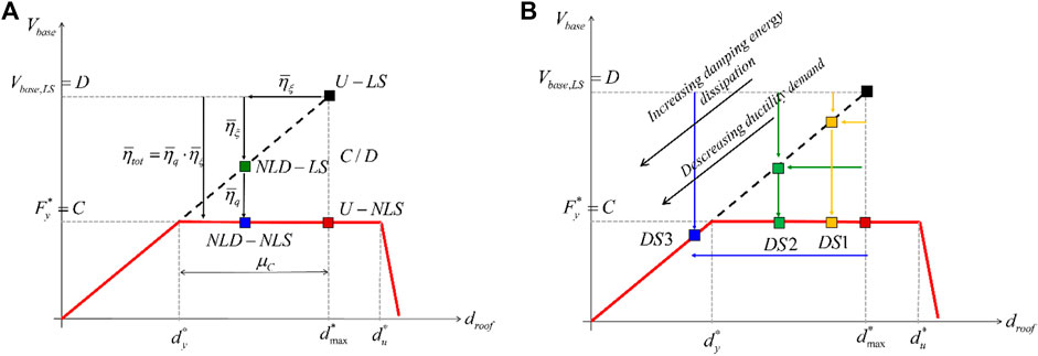
FIGURE 1. (A) Illustration of the target performance point, identified by the blue square (NLD). NL, non-linear response of the existing structure as it is. NLD, non-linear response of the existing structure with dampers. L, response of the equivalent linear structure. LD, response of the equivalent linear structure response with dampers. (B) Illustration of the design strategies, based on different distributions of the reduction factor of the seismic response between viscous dissipation and hysteretic dissipation.
The ductility capacity (
Once the total target reduction factor
If a behaviour factor
The target damping ratio
leading to:
It should be remarked that, since the ductility resources of the existing structure are limited to
If, instead, a target viscous damping ratio (
In the latter case, the designer should check that the obtained ductility demand is smaller than the ductility capacity, i.e.,
For illustrative purposes, three different design strategies (DS) are represented in Figure 1B, based on three different combinations of hysteretic and viscous dissipation. DS1 is mostly based on hysteretic dissipation, with a reduced amount of viscous damping provided by the added dampers. DS2 is mostly based on viscous damping (e.g., equivalent damping ratio larger than the one related to DS1), with a limited use of hysteretic dissipation, thus limiting structural damages. DS3 is uniquely based on viscous damping (e.g., equivalent damping ratio larger than the one related to DS2), thus completely avoiding structural damages.
3 The case study building
3.1 Building description and Finite Element analysis
The case study here considered is a 11-storey reinforced concrete building located in Bologna (Italy) and designed in the 1970s. The building has a rectangular shape in plan (Figure 2A) with dimensions equal to 44 m (along the longitudinal direction X) and 9.60 m (along the transversal direction Y). It has a total height of 33 m, while the inter-storey height is equal to 3 m. The RC beams have the height contained within the floor thickness, while the columns have different rectangular cross-sections varying both in plan and elevation. The floors are oriented along the longitudinal (X) direction and are assumed to be rigid in their plane, due to the presence of a 5 cm thick concrete slab. Each floor has a total thickness of 25 cm. Class C25/30 concrete and B450C steel are considered. The reinforcement bars are evaluated according to the “simulated design approach” starting from the original design drawings and considering the design rules and code requirements at the time of the design. More in detail, the longitudinal reinforcement bars in the columns were designed to have a cross sectional area larger than 0.5% of the gross area of the concrete section and globally higher than 1%. The longitudinal reinforcement bars in the beams were designed to have a cross a sectional area larger than 0.15% of the gross area of the concrete section, both in the tension side and in the compressed side.
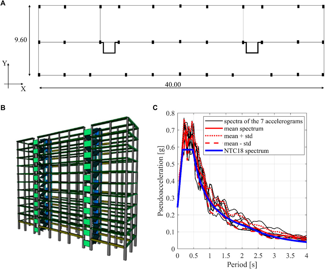
FIGURE 2. (A) Structural building plan. (B) SAP 2000 3D FE model. (C) Pseudoacceleration spectra of the 7 artificial earthquakes compared with the elastic design spectrum of the Italian code (NTC, 2018).
The Finite Element (FE) analyses are carried out using the commercial software SAP2000 NL (Comput. Struct. Inc, 2007). Both linear and non-linear FE models are considered. The non-linear behaviour of the structural elements (i.e., beams and columns) is modeled with flexural plastic hinges placed at both ends of each beam and column. The bending moment–curvature diagram of each plastic hinge has been evaluated on the basis of the actual reinforcement bars and of the axial force corresponding to dead and live loads at their characteristic values, without load partial safety factors (i.e., rare combination at the Serviceability Limit State); isotropic hysteresis type has been assumed. Shear failure has not been considered. The assumption is reasonable in case the shear strength of all the structural elements would be adequately increased by means of localized structural reinforcement interventions (e.g., bands with fiber-reinforced polymeric materials) aimed at: 1) guaranteeing a shear strength higher than the shear force corresponding to the formation of bending plastic hinges (bending capacity suitably increased with overstrength factors), according to the capacity design; 2) increasing the ductility capacity of the cross-section. The viscous dampers, sized to achieve the desired seismic performances, as detailed in Section 4, are modeled using NL-link elements. Both linear (with linear damping coefficient
In detail, a total number of 14 different FE models have been developed, including:
• Two undamped (U) models. They are representative of the as-built building without added dampers, namely, an undamped linear model (U-LS) and an undamped non-linear model (U-NLS).
• Six damped (D) models with linear structural elements (LS) and linear or non-linear dampers (LD or NLD). They are representative of the retrofitted building according to the DS1, DS2 and DS3 design strategies.
• Six damped (D) models with non-linear structural elements (NLS) and linear or non-linear dampers (LD or NLD). They are representative of the retrofitted building according to the three different design strategies (DS1, DS2 and DS3) fully detailed in Section 3.3.
The nomenclature adopted to identify the different FE models of the case study building is summarized in Table 1.
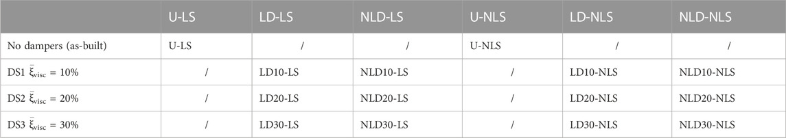
TABLE 1. The nomenclature adopted for all the developed FE models-.
The SAP2000 undamped FE model is represented in Figure 2B.
The linear and non-linear FE models, as listed in Table 1, are used to carry out the FE analyses necessary to verify the seismic performances. Equivalent static analyses and non-linear static analyses are carried out on the U-LS and U-NLS models to evaluate the seismic vulnerability of the as-built building and to compute the C/D ratio.
The linear and non-linear dynamic time-history analyses are conducted on both the undamped models and the damped models. The seismic input consists of a set of 7 artificial accelerograms generated with the software SIMQKE (Vanmarcke et al., 1990), using as Intensity Measure the Peak Ground Acceleration (PGA) and in order to be compatible with the design elastic spectrum associated to the “rare” earthquake design level, according to the Italian code (NTC, 2018). However, within the proposed procedure various and/or vector-valued Intensity Measures (Palermo et al., 2014; Castaldo and Miceli, 2023) and different spectral shapes can be adopted to select natural or artificial ground motions. Figure 2C shows the pseudoacceleration response spectra of the 7 artificial seismic records.
The fundamental periods of vibration are determined through a modal analysis conducted on the U-LS model of the structure. The first mode of vibration has a translational mode shape along the X direction and a period of vibration equal to 1.58 s. The second mode of vibration has a translational mode shape along the Y direction and a period of vibration equal to 2.29 s.
3.2 The seismic vulnerability analysis
The assessment of the seismic vulnerability of the as-built structure has been conducted by performing two sets of non-linear static (e.g., pushover) analyses with the floor horizontal forces applied along the X and Y directions. Two along-the-height distributions of lateral floor forces are considered: 1) uniform and 2) proportional to the fundamental modal shape.
Figure 3A shows the pushover curves (continuous line) along the X and Y direction, for both uniform and first-mode proportional lateral loads distribution, in terms of
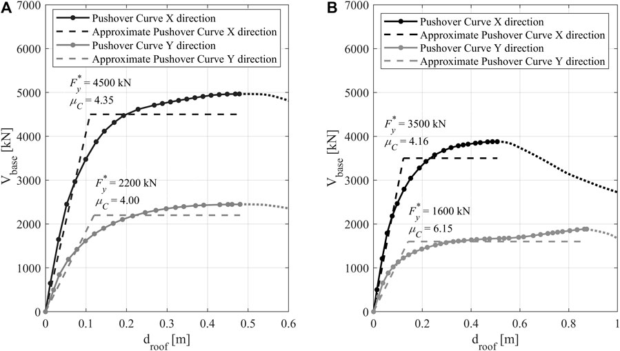
FIGURE 3. Pushover curves as obtained with: (A) uniform distribution of lateral floor forces; (B) lateral forces proportional to the first mode shape.
The base shear demand is evaluated through two equivalent static analyses developed along the X and Y directions. The horizontal floor loads are estimated from the elastic design spectrum ordinate at the fundamental periods (
3.3 Design strategies for the seismic retrofitting
The “direct five-step procedure” adapted to existing buildings, as discussed in Section 2, has been implemented to design the system of added viscous dampers. The damping system configuration is characterized, as shown in Figure 4A, by 16 devices at each storey, 8 of them working along the X direction, while the remaining 8 working along the Y direction.
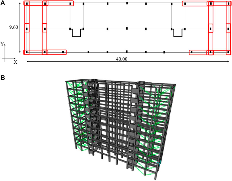
FIGURE 4. (A) Plan view with identification of the spans where the dampers are located. (B) SAP 2000 3D FE model of the building with the added viscous dampers.
The design of the damping system is performed assuming a total target reduction factor (STEP 1) equal to
In each DS, a precise value for the equivalent viscous damping ratio (
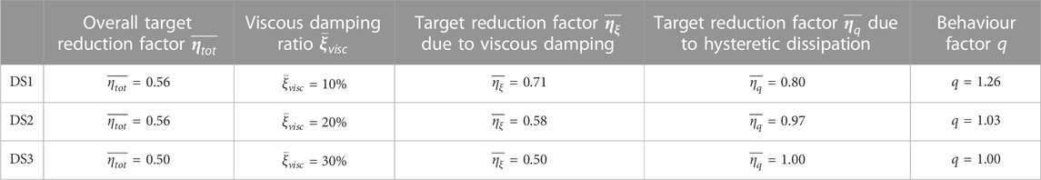
TABLE 2. Summary of the target performances for the three design strategies.
As already mentioned in Section 2.2, the target reduction factors are evaluated with reference to the global response of the structure (pushover curve). However, in the design phase, also the local response of the structural elements should be checked and the required specific local strengthening interventions must be designed.
4 The verification of the actual seismic performances
The verification of the actual seismic performances of the case study building is carried out through linear and non-linear dynamic time-history analyses, considering the FE models listed in Table 1 and represented in Figure 4B (corresponding to the three design strategies) and the set of the seven artificial seismic records, as described in Section 3.2.
Figure 5 graphically summarizes the main results of the dynamic analyses in terms of
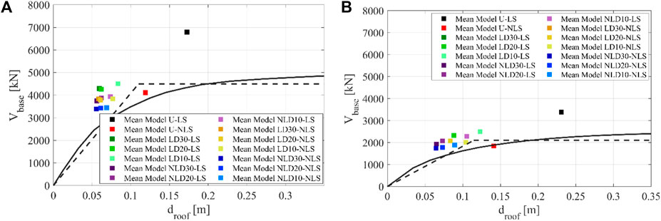
FIGURE 5. (A) Mean structural response along the X direction due to 7 artificial seismic events. (B) Mean structural response along the Y direction due to 7 artificial seismic events.
The obtained results can be quantitatively interpreted by introducing several response reduction factors related to the base shear,
• The inelastic response due to hysteretic dissipation for the undamped structure. It is quantified by comparing the responses of the U-LS and U-NLS models:
• The viscous energy dissipation due to the dampers. It is quantified by comparing the responses of the U-LS and NLD-LS models:
• The effectiveness of the equivalent energy criterion adopted to dimension the non-linear dampers. It is quantified by comparing the responses of the LD-LS and NLD-LS models:
• The inelastic response due to hysteretic dissipation for the damped structure. It is quantified by comparing the responses of the NLD-LS and NLD-NLS models:
• The theoretical total reduction due to the hysteretic and viscous dissipation. It is quantified by comparing the responses of the U-LS and NLD-NLS models:
• The actual total reduction due to the hysteretic and viscous dissipation. It is quantified by comparing the responses of the U-NLS and NLD-NLS models:
Table 3 summarizes the definitions of the response reduction factors and their reference/check values.
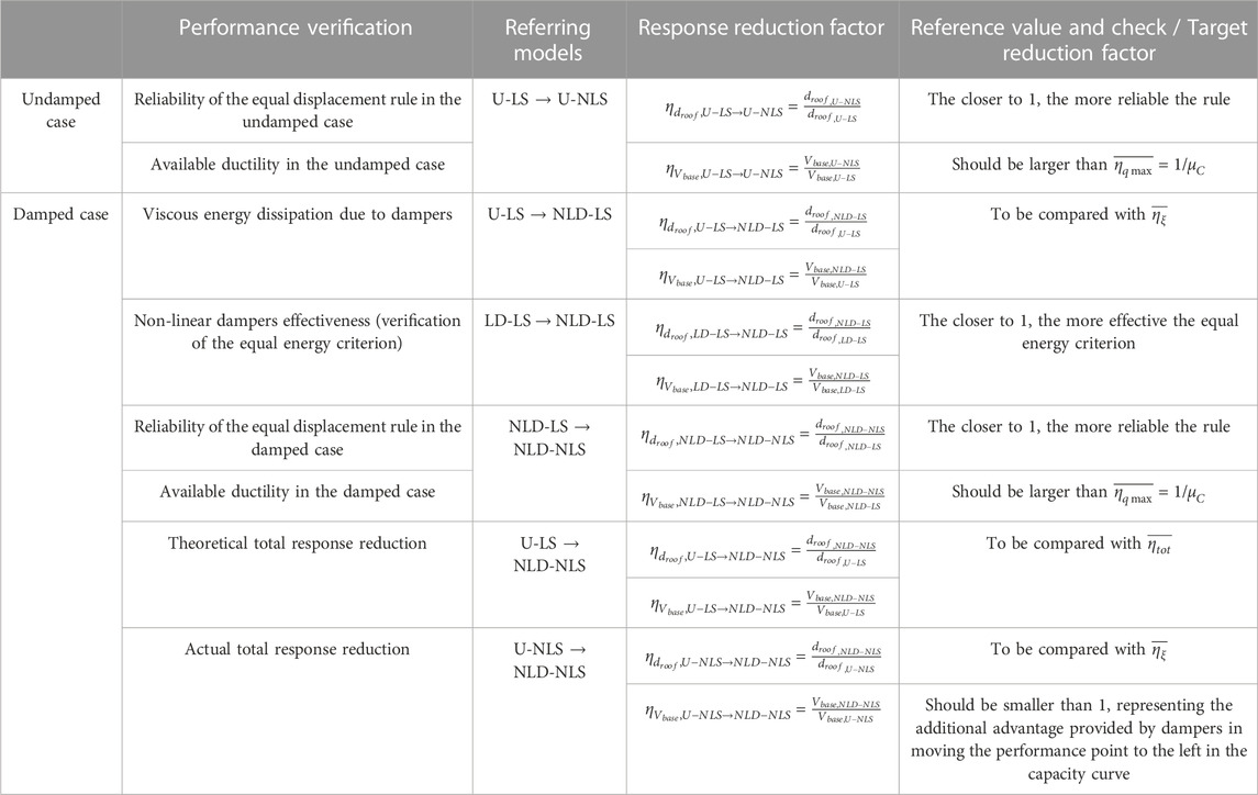
TABLE 3. Summary of the definitions of the response reduction factors and their reference/check values.
For the sake of clearness, Figure 6 provides a graphical representation of the above introduced response reduction factors limited to the DS2. Similar graphs were obtained for the other two design strategies. However, for the sake of conciseness, they are not reported in the paper. The graphical representation of Figure 6 allows us to better appreciate the relationship between the effects of the added dampers and the non-linear structural behaviour on the global structural response and the reduction factors.
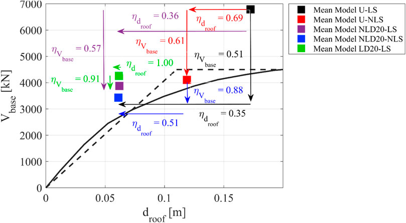
FIGURE 6. Structural response from dynamic time-history analysis of DS2 models with graphical identification of the response reduction factors through arrows.
The values of the response reduction factors obtained for the three considered DS are summarized in Table 4 and compared with the corresponding target values.
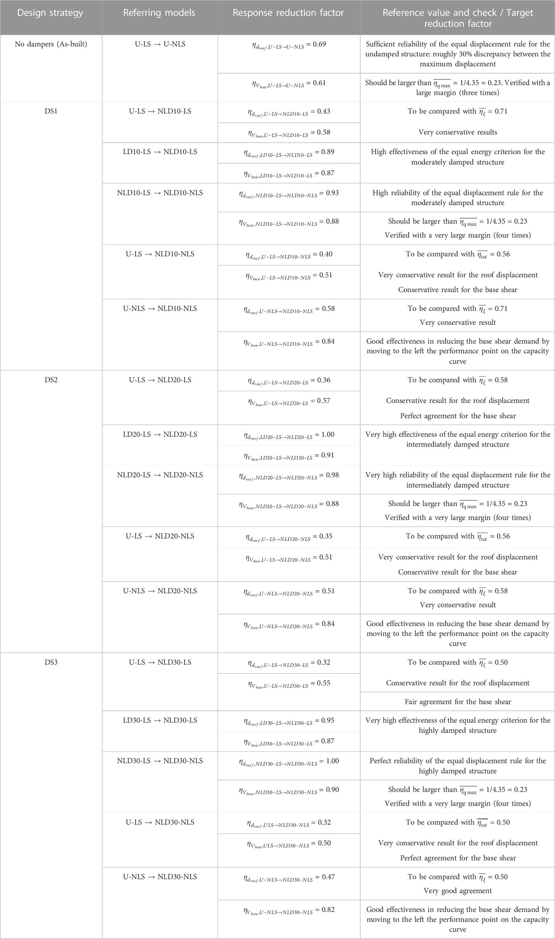
TABLE 4. Values of the response reduction factors obtained for the three design strategies.
The following observations can be made when comparing the performances of undamped linear and non-linear models:
• The actual base shear reduction factor (
• The obtained value of the roof displacement reduction factor (
The following observations can be made when comparing the performances of the models corresponding to the three different design strategies:
• Overall, the three design strategies lead to a very high energy dissipation capacity (comparison between
• Overall, for the three design strategies the damped models with non-linear dampers exhibit a higher effectiveness with respect to the corresponding damped models with linear dampers (both
• Overall, the three design strategies lead to theoretical global performances (comparison between
• Overall, the three design strategies lead to actual global performances in terms of displacement response (comparison between
It should be noted that the obtained numerical results are always affected by model (epistemic) uncertainties that lead to unavoidable discrepancies between the theoretical predictions, either analytical or numerical, and the actual response of the structure (especially in the case of non-linear models (Castaldo et al., 2020)) which hence should be considered in design applications.
5 Conclusion
The paper presented a new formulation of the “direct five-step procedure” for the design of added viscous dampers to be inserted into existing buildings. The main aim of the procedure is to ensure a seismic upgrade through a proper combination of the viscous dissipation provided by the added fluid-viscous dampers together with the hysteretic dissipation associated with the possible excursion of the structural elements into the inelastic regime. The combination of the two sources of energy dissipation leads to the introduction of a total target reduction factor, which can be evaluated as the product of the damping reduction factor (associated with the equivalent viscous damping ratio provided by the added dampers) and the hysteretic reduction factor (corresponding to the inverse of the assumed behavior factor). Clearly, the behavior factor should be selected in order to be compatible with the ductility capacity of the building (i.e.,
The procedure was then applied to an existing reinforced concrete case study building located in Bologna (Italy), by comparing three design strategies based on a different combination of the two sources of energy dissipation. The first strategy is based on a reduced amount of viscous damping with the structure expected to exceed the elastic limit. The second strategy is based on a moderate amount of viscous damping with the structure expected to behave around the yielding point. Finally, the third strategy is based on a high amount of viscous damping which should lead to a full elastic structural response. The seismic performances of the building with the three different damping systems were finally verified through dynamic non-linear time history analyses.
The obtained results indicate that the procedure is capable to achieve the desired target performances in terms of base shear and roof displacement reduction. In fact, for the three analyzed cases, the predictions in terms of base shear and roof displacement were almost in line or conservative with respect to the expectations (i.e., the obtained reduction factors resulted to be smaller than the corresponding target values). This is a desirable property of a design method which is targeted for the preliminary design phase.
In general, higher viscous energy dissipation is observed in the three design strategies leading to higher reductions of the roof displacements with respect to the target ones. This result was already noticed in previous works related to the application of the five-step procedure to new buildings and is mainly attributed to the higher effectiveness of the non-linear dampers with respect to the equivalent linear ones.
The obtained results allow us to state that the method is enough accurate for preliminary design purposes and it is quite effective for a quick comparison between different design strategies. On the other hand, the final design and verifications should, in any case, be conducted by means of dynamic non-linear time history analysis.
Data availability statement
The raw data supporting the conclusion of this article will be made available by the authors, without undue reservation.
Author contributions
MM: Writing–original draft, Data curation, Investigation, Software, Visualization. MP: Conceptualization, Methodology, Supervision, Writing–review and editing, Validation. SS: Conceptualization, Methodology, Supervision, Writing–review and editing, Funding acquisition, Validation.
Funding
Financial support of Department of Civil Protection (DPC-RELUIS 2019–2021 Grant and DPC-RELUIS 2022–2024 Grant, research line WP15: “Contributi normativi relativi a Isolamento e Dissipazione”) is gratefully acknowledged.
Acknowledgments
The former master students Luca D’Alonzo and Camilla Rita Valente are thanked.
Conflict of interest
The authors declare that the research was conducted in the absence of any commercial or financial relationships that could be construed as a potential conflict of interest.
The reviewer DF declared a past co-authorship with the authors MP, SS to the handling editor.
The authors SS and MP declared that they were editorial board members of Frontiers, at the time of submission. This had no impact on the peer review process and the final decision.
Publisher’s note
All claims expressed in this article are solely those of the authors and do not necessarily represent those of their affiliated organizations, or those of the publisher, the editors and the reviewers. Any product that may be evaluated in this article, or claim that may be made by its manufacturer, is not guaranteed or endorsed by the publisher.
References
Bommer, J. J., Elnashai, A. S., and Weir, A. G. (2000). Compatible acceleration and displacement spectra for seismic design codes, Proceedings of the 12th world conference on earthquake engineering, Auckland, New Zealand, January, 2000.
Castaldo, P., Gino, D., Bertagnoli, G., and Mancini, G. (2020). Resistance model uncertainty in non-linear finite element analyses of cyclically loaded reinforced concrete systems. Eng. Struct. 211, 110496. doi:10.1016/j.engstruct.2020.110496
Castaldo, P., and Miceli, E. (2023). Optimal single concave sliding device properties for isolated multi-span continuous deck bridges depending on the ground motion characteristics. Soil Dyn. Earthq. Eng. 173, 108128. doi:10.1016/j.soildyn.2023.108128
Christopoulos, C., and Filiatrault, A. (2006). Principles of passive supplemental damping and seismic. Pavia, Italy: IUSS Press.
Comput. Struct. Inc, (2007). SAP2000, “Integrated software for structural analysis & design. Berkeley, CA, USA: Comput. Struct. Inc.
Constantinou, M. C., and Symans, M. D. (1993). Seismic response of structures with supplemental damping. Struct. Des. Tall Build. 2 (2), 77–92. doi:10.1002/tal.4320020202
Constantinou, M. C., and Symans, M. D. (1992). Experimental and analytical investigation of seismic response of structures with supplemental fluid viscous dampers. New York, NY, USA: National Center for earthquake engineering research Buffalo.
C.S.LL.PP. Consiglio Superiore dei Lavori Pubblici (2019). Circolare n. 7 del 21/01/2019: Istruzioni per l’applicazione dell’«Aggiornamento delle “Norme tecniche per le costruzioni”» di cui al decreto ministeriale 17 gennaio 2018. GU n.35 del 11-2-2019 - Supplemento. Ordinario n. 5. Rome, Italy: Ufficio Pubblicazione Leggi e Decreti - Via Arenula.
Eurocode 8 (2005). Eurocode 8: design of structures for earthquake resistance-part 1: general rules, seismic actions and rules for buildings. Brussels, Belgium: Brussels Eur. Comm. Stand.
Foti, D. (2014a). Response of frames seismically protected with passive systems in near-field areas. Int. J. Struct. Eng. 5 (4), 326–345. doi:10.1504/ijstructe.2014.065916
Foti, D., Bozzo, L., and Lopez-Almansa, F. (1998). Numerical efficiency assessment of energy dissipators for seismic protection of buildings. Earthq. Eng. Struct. Dyn. 27 (6), 543–556. doi:10.1002/(sici)1096-9845(199806)27:6<543::aid-eqe733>3.0.co;2-9
Foti, D. (2014b). On the seismic response of protected and unprotected middle-rise steel frames in far-field and near-field areas. Shock Vib. 2014, 1–11. doi:10.1155/2014/393870
Garcia, D. L. (2001). A simple method for the design of optimal damper configurations in MDOF structures. Earthq. spectra 17 (3), 387–398. doi:10.1193/1.1586180
Green, N. B. (1987). Earthquake resitant building design and construction. Amsterdam, Netherlands: Elsevier.
Kasai, K., and Kibayashi, M. (2004). JSSI manual for building passive control technology. PART-1 Man. contents design/analysis methods.
Landi, L., Pollioa, B., and Diotallevi, P. P. (2014). Effectiveness of different standard and advanced pushover procedures for regular and irregular RC frames. Struct. Eng. Mech. An Int. J. 51 (3), 433–446. doi:10.12989/sem.2014.51.3.433
Levy, R., and Lavan, O. (2006). Fully stressed design of passive controllers in framed structures for seismic loadings. Struct. Multidiscip. Optim. 32, 485–498. doi:10.1007/s00158-005-0558-5
Liang, Z., Lee, G. C., Dargush, G. F., and Song, J. (2011). Structural damping: applications in seismic response modification, 3. CRC Press.
Manual, J. (2003). Design and construction manual for passively controlled buildings. Japan: Japan Soc. Seism. Isol. JSSI.
NTC, (2018). Decreto Ministeriale del 17/01/2018: norme Tecniche per le Costruzioni. Roma, Italy: Ministero delle Infrastrutture.
Palermo, M., Muscio, S., Silvestri, S., Landi, L., and Trombetti, T. (2013a). On the dimensioning of viscous dampers for the mitigation of the earthquake-induced effects in moment-resisting frame structures. Bull. Earthq. Eng. 11, 2429–2446. doi:10.1007/s10518-013-9474-z
Palermo, M., Silvestri, S., Gasparini, G., and Trombetti, T. (2014). A statistical study on the peak ground parameters and amplification factors for an updated design displacement spectrum and a criterion for the selection of recorded ground motions. Eng. Struct. 76, 163–176. doi:10.1016/j.engstruct.2014.06.045
Palermo, M., Silvestri, S., Gasparini, G., and Trombetti, T. (2015). Seismic modal contribution factors. Bull. Earthq. Eng. 13, 2867–2891. doi:10.1007/s10518-015-9757-7
Palermo, M., Silvestri, S., Gasparini, G., and Trombetti, T. (2017b). Un metodo semplificato per il dimensionamento e l’analisi di strutture equipaggiate con smorzatori viscosi A simplified method for dimensioning and analyzing equipped structures with viscous dampers. Progett. sismica 8 (3), 9–24. doi:10.7414/PS.8.3.9-24
Palermo, M., Silvestri, S., Landi, L., Gasparini, G., and Trombetti, T. (2018). A ‘direct five-step procedure’ for the preliminary seismic design of buildings with added viscous dampers. Eng. Struct. 173, 933–950. doi:10.1016/j.engstruct.2018.06.103
Palermo, M., Silvestri, S., Landi, L., Gasparini, G., and Trombetti, T. (2016). Peak velocities estimation for a direct five-step design procedure of inter-storey viscous dampers. Bull. Earthq. Eng. 14, 599–619. doi:10.1007/s10518-015-9829-8
Palermo, M., Silvestri, S., Trombetti, T., and Landi, L. (2013b). Force reduction factor for building structures equipped with added viscous dampers. Bull. Earthq. Eng. 11, 1661–1681. doi:10.1007/s10518-013-9458-z
Palermo, M., Silvestri, S., and Trombetti, T. (2017a). On the peak inter-storey drift and peak inter-storey velocity profiles for frame structures. Soil Dyn. Earthq. Eng. 94, 18–34. doi:10.1016/j.soildyn.2016.12.009
Pekcan, G., Mander, J. B., and Chen, S. S. (1999). Fundamental considerations for the design of non-linear viscous dampers. Earthq. Eng. Struct. Dyn. 28 (11), 1405–1425. doi:10.1002/(sici)1096-9845(199911)28:11<1405::aid-eqe875>3.0.co;2-a
Ramirez, O. M., Constantinou, M. C., Whittaker, A. S., Kircher, C. A., and Chrysostomou, C. Z. (2002). Elastic and inelastic seismic response of buildings with damping systems. Earthq. Spectra 18 (3), 531–547. doi:10.1193/1.1509762
Ramirez, O. M., Constantinou, M. C., Whittaker, A. S., Kircher, C. A., Johnson, M. W., and Chrysostomou, C. Z. (2003). Validation of the 2000 NEHRP provisions’ equivalent lateral force and modal analysis procedures for buildings with damping systems. Earthq. Spectra 19 (4), 981–999. doi:10.1193/1.1622392
Ramirez, O. M. (2001). Development and evaluation of simplified procedures for the analysis and design of buildings with passive energy dissipation systems. New York, NY, USA: State University of New York at Buffalo.
Shea, G. H. (1999). Recommended lateral force requirements and commentary. California, CA, USA: Structural Engineers Association of California.
Shukla, A. K., and Datta, T. K. (1999). Optimal use of viscoelastic dampers in building frames for seismic force. J. Struct. Eng. 125 (4), 401–409. doi:10.1061/(asce)0733-9445(1999)125:4(401)
Silvestri, S., Gasparini, G., and Trombetti, T. (2010). A five-step procedure for the dimensioning of viscous dampers to be inserted in building structures. J. Earthq. Eng. 14 (3), 417–447. doi:10.1080/13632460903093891
Singh, M. P., and Moreschi, L. M. (2002). Optimal placement of dampers for passive response control. Earthq. Eng. Struct. Dyn. 31 (4), 955–976. doi:10.1002/eqe.132
Takewaki, I. (2011). Building control with passive dampers: optimal performance-based design for earthquakes. Hoboken, New Jersey, United States: John Wiley & Sons.
Takewaki, I. (2000). Optimal damper placement for critical excitation. Probabilistic Eng. Mech. 15 (4), 317–325. doi:10.1016/s0266-8920(99)00033-8
Takewaki, I. (1997). Optimal damper placement for minimum transfer functions. Earthq. Eng. Struct. Dyn. 26 (11), 1113–1124. doi:10.1002/(sici)1096-9845(199711)26:11<1113::aid-eqe696>3.0.co;2-x
Trombetti, T., Palermo, M., Dib, A., Gasparini, G., Silvestri, S., and Landi, L. (2015). Application of a direct procedure for the seismic retrofit of a R/C school building equipped with viscous dampers. Front. Built Environ. 1 (14). doi:10.3389/fbuil.2015.00014
Trombetti, T., and Silvestri, S. (2004). Added viscous dampers in shear-type structures: the effectiveness of mass proportional damping. J. Earthq. Eng. 8 (02), 275–313. doi:10.1080/13632460409350490
Trombetti, T., and Silvestri, S. (2006). On the modal damping ratios of shear-type structures equipped with Rayleigh damping systems. J. Sound. Vib. 292 (1–2), 21–58. doi:10.1016/j.jsv.2005.07.023
Vanmarcke, E. H., Cornell, C. A., Gasparini, D. A., and Hou, S. (1990). SIMQKE-I: simulation of earthquake ground motions. Cambridge, MA, USA: Dep. Civ. Eng. Massachusetts Inst. Technol.
Weng, D. G., Zhang, C., Lu, X. L., Zeng, S., and Zhang, S. M. (2012). A simplified design procedure for seismic retrofit of earthquake-damaged RC frames with viscous dampers. Struct. Eng. Mech. An Int’l J. 44 (5), 611–631. doi:10.12989/sem.2012.44.5.611
Whittaker, A. S., Constantinou, M. C., Ramirez, O. M., Johnson, M. W., and Chrysostomou, C. Z. (2003). Equivalent lateral force and modal analysis procedures of the 2000 NEHRP Provisions for buildings with damping systems. Earthq. Spectra 19 (4), 959–980. doi:10.1193/1.1622391
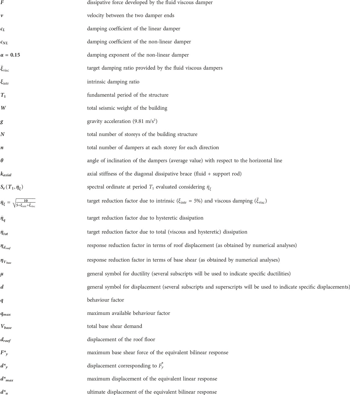
Nomenclature
Keywords: existing buildings, frame structures, fluid viscous dampers, design procedure, ductility capacity, applicative example
Citation: Marra M, Palermo M and Silvestri S (2023) The “direct five-step procedure” for the design of added viscous dampers to be inserted into existing buildings: formulation and case study. Front. Built Environ. 9:1289851. doi: 10.3389/fbuil.2023.1289851
Received: 06 September 2023; Accepted: 11 October 2023;
Published: 23 November 2023.
Edited by:
Antonio Formisano, University of Naples Federico II, ItalyReviewed by:
Mahdi Abdeddaim, University of Biskra, AlgeriaPaolo Castaldo, Polytechnic University of Turin, Italy
Dora Foti, Politecnico di Bari, Italy
Copyright © 2023 Marra, Palermo and Silvestri. This is an open-access article distributed under the terms of the Creative Commons Attribution License (CC BY). The use, distribution or reproduction in other forums is permitted, provided the original author(s) and the copyright owner(s) are credited and that the original publication in this journal is cited, in accordance with accepted academic practice. No use, distribution or reproduction is permitted which does not comply with these terms.
*Correspondence: Matteo Marra, bWF0dGVvLm1hcnJhNkB1bmliby5pdA==