 Yilin Li
 Yuke Peng
94% of researchers rate our articles as excellent or good
Learn more about the work of our research integrity team to safeguard the quality of each article we publish.
Find out more
ORIGINAL RESEARCH article
Front. Built Environ., 20 March 2023
Sec. Sustainable Design and Construction
Volume 9 - 2023 | https://doi.org/10.3389/fbuil.2023.1134590
The use of a phase change material (PCM) blind system has great potential in mitigating overheating issues in double skin facade (DSF) systems while maintaining their optical and thermal benefits. However, there is a lack of research information available regarding the optical properties of such systems. This paper establishes a solar radiation model of PCM blinds for use in a DSF system that integrates the optical path of sunlight. The influences of the solar incidence angle, slat inclination angle, the ratio of slat distance to slat width, and slat surface material on the optical coefficient of the blind system are analyzed. The results indicate slat inclination angle significantly affects diffuse absorptance and diffuse transmittance, while solar incidence angle has little impact. Diffuse absorptance gradually increases with increasing slat inclination angle, reaching a peak at 90°, while diffuse transmittance decreases. The optical coefficient of the blind is closely related to the ratio of slat distance to slat width. The smaller the slat inclination angle, the more noticeable the difference in absorptance or transmittance of direct/diffuse solar radiation. The reflectance of the blind surface material has a significant effect on the optical coefficient. As the reflectance of the slat surface material increases, both direct absorptance and diffuse absorptance of the slat show a decreasing trend. Our results suggest that this method could be used for optical properties measurement in PCM blind system. The results of this study provide effective references for the final selection of PCM and the estimation of component dosage.
Buildings have led to 30%–40% of the final energy consumption around the world (Colgan, 2006). In order to achieve energy conservation while reducing environmental impact, many passive energy consumption optimization strategies have been studied and utilized including double skin façade (DSF) and thermal energy storage (TES) material (Mirkovic and Alawadi, 2017; Sawadogo et al., 2021; Balali et al., 2023). DSF, as a type of building envelopes, are widely applied by architects and engineers due to its aesthetic beauty and thermal performance under different climatic conditions. However, it sometimes suffers from overheating problems during warm seasons especially in summer (Tanimoto and Kimura, 1997; Pasquay, 2004; Saelens et al., 2004).
As a type of TES materials, PCM have been commonly used in buildings. PCMs are the substances that absorb/release massive amount of heat energy during phase change with constant temperature (MOUSAVI BAYGI and SADRAMELI, 2018). Many researchers have applied PCMs as sunshade devices which are integrated with building envelopes due to their high energy storage density, abilities of reducing indoor temperature fluctuations, and potential of improving indoor thermal comfort. For example, Weinlaeder et al. (2011) monitored an indoor sunshade system composed of vertical blind filled with PCM. The results showed that even under long-term strong solar radiation, the internal surface temperature of the blind filled with PCM rarely exceeds the PCM melting temperature of 28°C, while the traditional indoor shading system can often reach a temperature above 40°C. Liu et al. (Liu et al., 2017; Liu et al., 2019) proposed a simplified calculation method considering convective heat transfer in the air layer and radiation heat transfer in the PCM layer. By using this model, they found that with the increase of PCM thickness, the time lag increases, and the inner surface temperature is close to room temperature, that is, the indoor temperature is smooth. In addition, they established a one-dimensional heat transfer model considering solar radiation for a glazing envelope containing translucent PCM, and analyzed the influence of absorptance and reflectance of PCMs on the temperature distribution and heat flow of the envelope. The results showed that the internal radiation transfer of glass envelope had a great impact on its heat transfer process. The increase of absorptance and reflectance of PCM is beneficial to the improvement of internal temperature distribution, heat flow, and optical transmission. Weinlaeder et al. (2011) monitored an interior sun protection system consisting of vertical slats filled with PCM. The result showed that the surface temperature on the interior side of the PCM-filled slats hardly ever exceeded the PCM melting temperature of 28°C even in case of long-term intense solar radiation. Contrast to a reference room with a comparable conventional blind, the sun protection system with PCM therefore considerably improves thermal comfort.
Great efforts have also been put in studying PCM blind integrated in DSF systems. PCM blind, as a type of thermal energy storage device in construction, is applicable in a DSF system to mitigate the problems of overheating in summer. For instance, Li et al. (2019) developed a novel laminated composite PCM blind system with high TES capacity and evaluated it in a typical DSF building. The results showed that the integrated PCM blind system was able to keep the average air temperature in the DSF below 35°C during the monitored period in summer and showed no significant increase as compared with the ambient temperature. They also found that the surface temperature of the inner skin of the DSF was also reduced up to about 2.9°C as compared with the external skin surface temperature thus reducing heat transfer into the building. Elarga et al. (2016) investigated the performance of a system that integrates a photovoltaic (PV) layer and PCM in a DSF. They found that the adoption of a PCM layer in the DSF cavity, in combination with a semi-transparent PV layer, leading to a reduction in the monthly cooling energy demand in the 20%–30% range in temperate continental climate, temperate continental climate, and tropical desert climate. Gracia et al. (2013) tested experimentally the thermal performance of a ventilated DSF with PCM in its air channel, during the heating season in Mediterranean climate.
There are plenty of previous research on the optical performance of DSF with the sunshade blind, however, so far little research information has been found on optical properties of PCM blind in a DSF system. For example, Mitalas. (1962) proposed an algorithm to calculate the absorptance and reflectance of DSF, which can accurately calculate the transmittance, absorptance, and reflectance of the transmission system under different conditions. Pfrommer et al. (1995) developed a thermal simulation model which can simulate blind system accurately at each simulation time-step and simulate blinds approximately using simplified daily effective shading factors for each radiation component. They also established the optical properties of the transmission system containing thin film or thin layer that can be calculated as a function of wavelength and incidence angle, and validated the accuracy of the model with measured data (Pfrommer et al., 1996). The ISO15099 (ISO15099-2003, 1509) issued by the International Standards Organization established the optical model for sunshade blinds by dividing the blinds into five equal pieces. Rubin et al. (2006) raised a model to calculate the optical properties of multilayer transmission system.
Although previous studies have been conducted on DSF integrated blind systems, there are few theoretical and experimental studies on the optical properties of the integrated DSF and PCM blind system. There is still lack of comprehensive understanding on the optical and thermal performance of the PCM blind and its application in DSF systems. To further explore the role and impact of solar radiation on the integrated DSF and PCM blind system, it is of great significance to establish a solar radiation model for the integrated system which considers the optical properties of the PCM blind, validate the accuracy of the model, and carry out both theoretical and experimental research to analyze the influence of different design and operational parameters on the integrated system. The findings of this research will provide a theoretical basis for material screening, PCM preparation, and optimal design of integrated DSF and PCM blind systems in future.
As shown in Figures 1, the optical path of the solar radiation reaching the DSF and penetrating through the system is analyzed. The total solar radiation attenuates through the atmosphere and firstly reaches the external surface of the outer glass skin of the DSF. The direct solar radiation that passes through the outer glass skin can be divided into three parts: transmission, reflection, and absorption. The transmitted solar radiation and a proportion of absorbed solar radiation reaches the surface of the PCM blind or exchange heat with the air in the cavity. The excessive solar radiation is absorbed by the PCM blind during the phase transition process when the cavity temperature reaches the melting point. The absorbed heat will then be released into the cavity air through the process of conduction, convection, and radiation. The remaining solar radiation diffusely reflects or transmits on the PCM blind, and reaches to the inner glass skin. After transmission, reflection, and absorption on the inner glass skin, a small amount of solar radiation eventually enters the room, and becomes a source of natural daylighting and indoor solar heat gain.
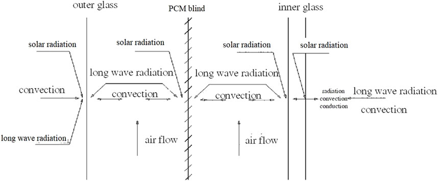
FIGURE 1. Heat transfer process of the integrated PCM blind and DSF system.
When calculating the solar heat gain through the integrated DSF and PCM blind system, it is essential to comprehensively understand the optical behaviors which influenced by the geometric structure and position of the blind. The following assumptions are made for establishing the mathematical model of the PCM blind system.
1) The slats of the PCM blind are evenly distributed both horizontally and vertically, ignoring slight deflection in the length direction of the slats;
2) The theoretical model of the integrated system was simplified as a 2D-model, regardless of the sickness of the slat;
3) Only the downward inclination of the blind was considered;
4) The PCM blind surface is assumed to be a diffuse reflection surface and the blind transmittance is 0
5) Only the secondary reflections between blinds were considered;
6) The solar incidence angle was not considered when calculating the diffuse radiation;
7) The integrated system is adiabat and the influence of the frame of the DSF was neglected.
According to Chinese industrial standard (Code for Thermal), the following six optical parameters shall be determined and calculated to establish the optical model of a solar shading device to evaluate its performance.
1) Direct-to-direct transmittance
2) Direct-to-direct reflectance
3) Direct-to-diffuse transmittance
4) Direct-to-diffuse reflectance
5) Diffuse-to-diffuse transmittance
6) Diffuse-to diffuse reflectance
The direct-to-direct transmittance of the PCM blind can be calculated by Eq. 1 (Ma, 2003):
where
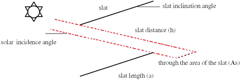
FIGURE 2. Schematic diagram of direct sunlight through PCM blades.
The transparent part of the PCM blind has no reflection. Since the surface is assumed to be a diffuse reflection surface and the blind transmittance is 0, the direct-to-direct reflectance of the blinds is 0. According to the geometric dimensions of the PCM blind and the solar incidence angle, direct solar transmittance can be calculated. In addition, the critical angle of direct solar radiation is only related to the slat geometry. The critical angle
Where h represents the slat distance, a is the slat length,
Since most of the transmitted solar radiation is reflected among the slats of the PCM blind, the secondary reflections among the slats were considered. The slat surface radiance is 0 due to that the slat has a diffuse reflection surface. In order to calculate the direct-to-diffuse solar radiation, the ajacent two slats of the PCM blind can be divided into several regions as shown in Figure 3. For each layer k and spectral interval
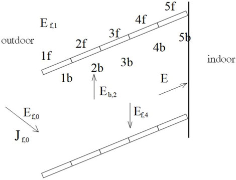
FIGURE 3. Diagram of divided slat regions for PCM blind (Li, 2010).
Where
According to the radiation balance between interfaces, the following relationship exists:
The variables used in the equation are defined as follows:
Based on the above analysis, the radiation model of two adjacent slats was established as shown in Figure 4. Two adjacent slats form a virtual blind cavity, and each of the slat can be divided into four regions (1f, 2f, 1b, 2b) according to their conditions of exposure to direct solar radiation. In Figure 4, the dotted line with an arrow indicates the incidence direction of direct sunlight. When the direct radiation is projected onto the PCM blind, the surface of 1f can receive direct radiation and is called a bright-spot region, while 2f does not receive any direct solar radiation directly and is called a dark-spot region. After numerous times of diffuse reflections among the surfaces of 1b, 2b, 1f, and 2f, part of the diffuse radiation leaves the blind cavity from the left sides of the slat surfaces, forming direct-to-diffuse reflected radiation. The remaining part of the diffuse radiation leaves the blind system from the right sides, forming direct-to-diffuse transmission radiation. If there are only bright-spot regions on the slat, the slat can be divided into two parts: 1f and 1b.
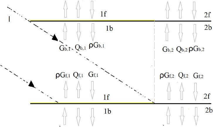
FIGURE 4. Radiation between two adjacent slats.
According to the principle of net radiation, the corresponding radiation balance equations were established for 1f, 2f, 1b, and 2b surfaces respectively:
Where
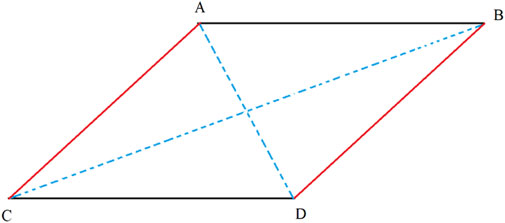
FIGURE 5. Diagram of angle factor between surfaces.
Where
The Eqs 5–8 can be further derived as Eqs 12–15, and then organized into a matrix.
The direct-to-diffuse radiation reflected by the blind
The ratio of the radiant energy directly projected from surface S on the left inlet of the blind to surface 1f to the effective radiant energy of surface 1f is represented by
Then the direct-to-diffuse reflection of the PCM blind is:
Where
Where
Regarding the diffuse-to-diffuse solar radiation model, when the solar incidence angle is greater than 60°, the transmittance decreases sharply, and the absorptance, reflectance, and transmittance of the glass under diffuse radiation are close in value to those for direct radiation with a solar incidence angle of 45°–60° (Code for Thermal). M. Gloria suggest that the optical performance of the glass for direct radiation at a solar incidence angle of 45° is approximated as its optical performance for solar diffuse radiation (Gloria Gomes et al., 2012). Some scholars believe that the absorption, reflection, and transmittance properties of the glass medium layer for diffuse solar radiation are independent of the solar incidence angle. As an approximation for the optical properties of PCM blind with diffuse-to-diffuse, the optical properties of PCM blind with direct radiation at a solar incidence angle of approximately 60° are used (Li, 2010).
The PCM blind in a DSF System features a complex structure, where the diffuse optical parameters of the single-layer glass are used repeatedly in the calculation process, ultimately influencing the diffuse-to-diffuse optical properties of the DSF system. The incidence beam of diffuse radiation shines on the glass surface from all directions, and the physical properties of the material, as well as the manufacturing process, may differ for different glass materials and thicknesses, making it impossible to generalize the optical properties of DSF. As such, the optical properties of DSF must be analyzed based on specific circumstances.
In this study, the diffuse-to-diffuse radiation transmittance of the blind is defined as
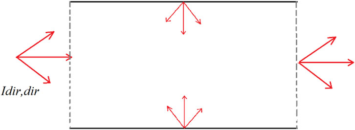
FIGURE 6. Schematic diagram of diffuse-to-diffuse radiation.
Due to assumptions that the slats are ideal diffusers, the method for calculating optical properties of blind with the direct-to-diffuse radiation is consistent with the model for calculating optical properties of blind with the direct-to-diffuse radiation. The equations for calculating the diffuse-to-diffuse radiation is as follow:
For the sake of convenience in calculation,
Then the diffuse-to-diffuse reflectance of the PCM blind is:
The diffuse-to-diffuse transmittance of the PCM blind is:
The validation of the model was conducted by comparing with experimental data obtained by Duffie and Beckman. (1991). The experimental platform was composed of 6 mm thick single-layer glass and an external aluminum blind system. The slat was installed horizontally with adjustable angle, and surface reflectance of 0.40. The width of each slat is 0.08 m and the gap between each two slats is 0.068 m. Two solar irradiance sensors were installed in front of and behind the blind system respectively to measure the solar radiation data. The data logger recorded data at a time step of 10 min.
Figure 7 shows the comparison between the theoretical and measured transmittance of the slat at 10:00 and 14:00 for different slat angles. As the slat inclination angle increases from small to large, the changing trend of the theoretical and measured values of transmittance are consistent at different times. At 10:00, the average error is 0.09, and the maximum error occurs when the slat inclination angle is 15° and 30°, with a value of 0.14. At 14:00, the average error is 0.04, and the maximum error occurs when the slat inclination angle is 60°, with a value of 0.11.
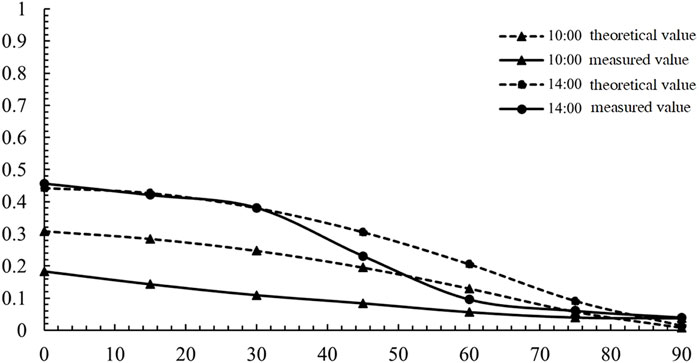
FIGURE 7. Comparison of theoretical and measured transmittance values of blind with different slat inclination angles.
The comparison between the theoretical total transmittance and the measured transmittance of the slats at different times when the slat inclination angle is 30° and 45° is shown in Figure 8. At a slat inclination angle of 30°, the average error is 0.084. The maximum error occurs at 12:00, with an error value of 0.15. At a slat inclination angle of 45°, the average error is 0.075, and the maximum error occurs at 8:00, with an error value of 0.14.
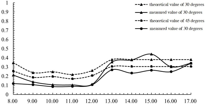
FIGURE 8. Comparison of theoretical and measured transmittance values of blinds at different times.
As shown in Table 1, the comparison of experimental data and theoretical results were also statistically analyzed by using the normal test function in SPSS software. A Student t-test was applied and the results reveal that the p-values of the samples are all greater than 0.05, which indicates that no significant difference can be found between the theoretical and the measured values.
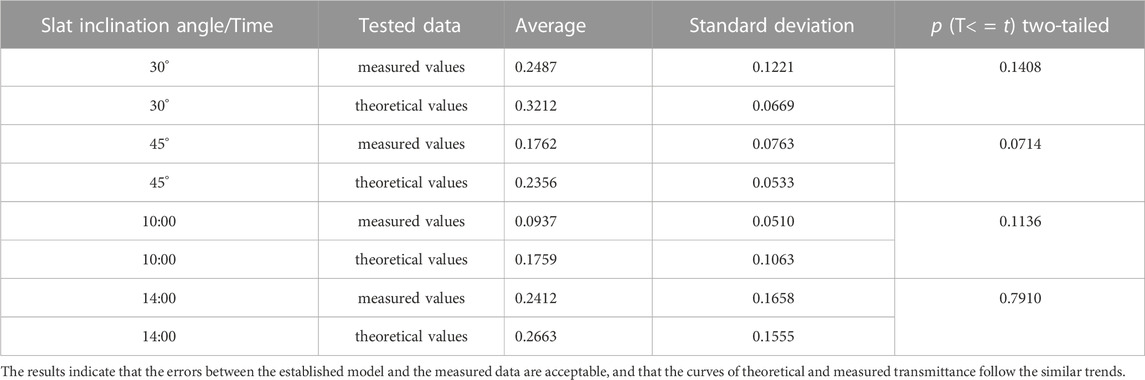
TABLE 1. Test results of significant difference between theoretical results and measured data.
Figure 9 comparatively studies the solar radiation absorptance and transmittance of the slat at different solar incidence angles (10°, 15°, 30°, 45°, 60°, and 90°), and explores the influence of the slat angle on the optical performance of the blind system. The calculation process assumes a ratio of slat distance (sd) to slat width (sw) of 1:1, an aluminum alloy slat, a surface reflectance of 0.40, and an absorptance of 0.60 for the surface material.
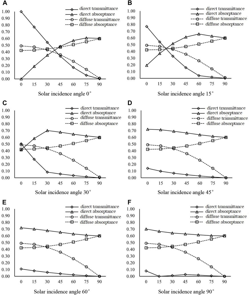
FIGURE 9. Effect of different slat inclination angles on the optical performance of PCM blind. (A) Solar incidence angle 0° (B) Solar incidence angle 15° (C) Solar incidence angle 30° (D) Solar incidence angle 45° (E) Solar incidence angle 60° (F) Solar incidence angle 90°.
As presented in Table 2 the diffuse absorptance and diffuse transmittance are independent of the solar incidence angle, and only dependent on the slat inclination angle. The diffuse absorptance increases gradually with the angle, reaching its peak when the slat inclination angle is 90°, while the diffuse transmittance decreases gradually with the angle.
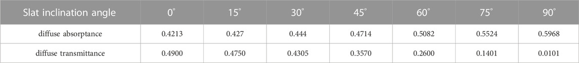
TABLE 2. Summary of diffuse absorptance and diffuse transmittance, for different slat inclination angles.
As shown in Figure 9A and Table 3, when the solar incidence angle is 0°, the direct transmittance gradually decreases with an increase in the slat inclination angle, and the direct absorptance firstly rises, reaching a peak when the slat inclination angle is within 60°–75°, and then slowly reduces. This phenomenon can be explained by the solar radiation model presented in Section 2. On one hand, as the slat inclination angle increases, a portion of direct sunlight is projected onto the slat and enters the room through several rounds of diffuse reflection, while the rest enters through the gaps between the adjacent slats. When the slat inclination angle reaches a critical angle, the direct solar transmittance decreases to 0. As direct sunlight diffuses through the blind, a portion of it deviates away from the blind’s left side, resulting in lower direct transmittance. On the other hand, as the slat inclination angle increases, the slat surface will continue to be radiated by direct sunlight. According to Eqs 9, 19, the angle coefficient will increase, resulting in an increase in direct reflectance. Since the gap is relatively large, the proportion of direct reflection in total direct sunlight is less than direct transmission. As the slat inclination angle increases, the gap decreases, and after reaching a critical point, the proportion of direct reflection exceeds that of direct transmission. As a result, the direct absorptance first increases and then decreases.
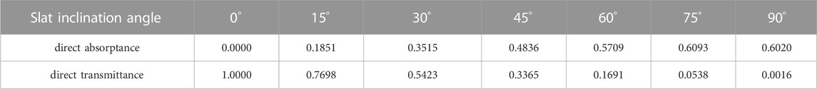
TABLE 3. Summary of direct absorptance and direct transmittance, for different slat inclination angles.
In Table 4, the values of direct transmittance and direct absorptance at different solar incidence angles are summarized when the slat inclination angle is 45°. It can be observed that direct absorptance and direct transmittance are closely related to the solar incidence angle. When the solar incidence angle is less than 45°, the direct absorptance gradually increases to a peak value as the slat inclination angle increases, then gradually decreases and approaches a stable value. The main reason for the decrease in direct absorptance with increasing solar incidence angle is that at angles less than 45°, major proportion of direct sunlight passes through the PCM blind and is transmitted directly. However, as the solar incidence angle increases, the amount of direct transmission decreases while the proportion of direct-to-diffuse radiation increases. This shift results in an increase in direct absorptance until the direct radiation on the slat surface is completely blocked, causing the solar radiation to shift from partial direct-to-diffuse radiation to total direct-to-diffuse radiation. As a result, increasing the solar incidence angle leads to a slight decrease in direct absorptance. When the solar incidence angle is greater than 45°, the direct absorptance gradually decreases with increasing solar incidence angle, eventually approaching the absorptance of the material itself.
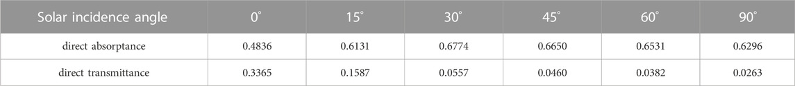
TABLE 4. Summary of direct absorptance and direct transmittance, for different solar incidence angles.
Figure 10 compares and analyzes the effects of different ratios of slat distance to slat width on the solar radiation absorptance and transmittance of PCM blinds at the same solar incidence angle and different slat inclination angles. For calculation, the solar incidence angle is 45°, the slat inclination angles are 0°, 30°, 45°, and 90°, respectively, and the ratio of slat distance to slat width is 0.5, 0.7, 0.9, 1.0, 1.2, and 1.5, respectively. The slats are made of aluminum alloy with a surface reflectance coefficient of 0.40 and an absorptance of 0.60. The influence of slat thickness on the optical coefficient of the blind is not taken into account.
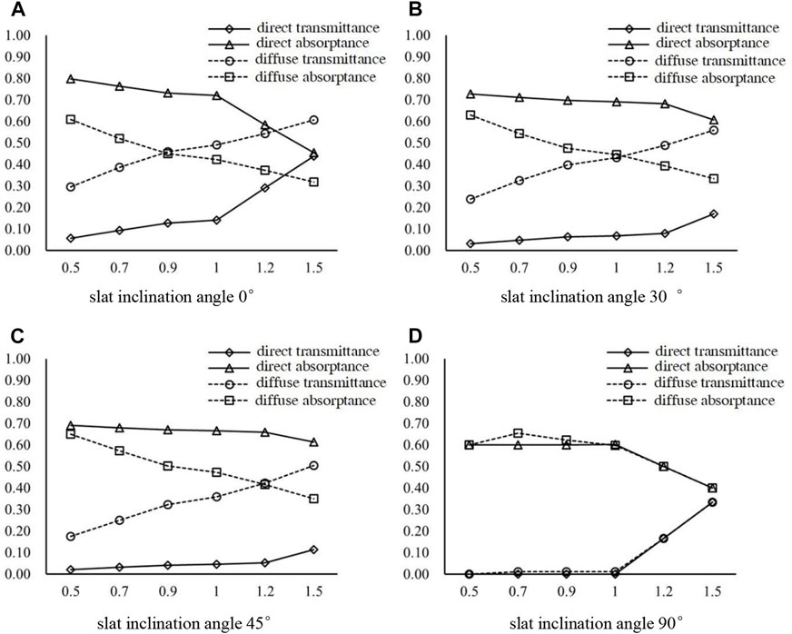
FIGURE 10. Effect of different ratios of slat distance to slat width on the optical performance of PCM blind. (A) slat inclination angle 0° (B) slat inclination angle 30° (C) slat inclination angle 45° (D) slat inclination angle 90°.
It can also be observed from Figure 10A and Table 5 that the optical coefficient of the PCM blind is dependent on both the slat inclination angle and the ratio of slat distance to slat width.
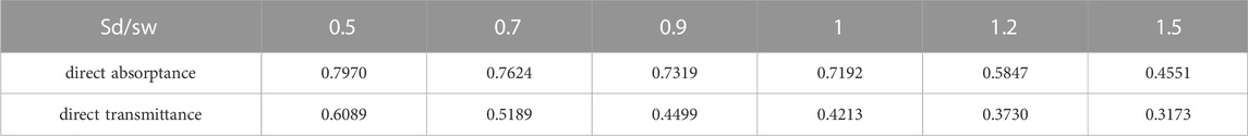
TABLE 5. Summary of direct absorptance and direct transmittance, for different ratios of slat distance to slat width.
With an increase in the slat distance to slat width ratio, the direct radiation absorptance first slowly decreases, and then drops sharply when it reaches a critical point (i.e., when the ratio of slat distance to slat width is 1.0). The main reason for this is that when the slat distance increases or the slat width decreases, the total area of the blind slat becomes smaller, resulting in more direct light passing through the blind system.
When the slat inclination angle is 90°, the coefficients of direct and diffuse radiation overlap to some extent. When the ratio of slat distance to slat width is less than 1.0, the absorptance of diffuse and direct radiation remains at around 0.60. With an increase in the slat distance, the absorptance of direct or diffuse radiation decreases linearly. This is mainly because when the slat distance increases, the total area of the blind decreases linearly, allowing more solar radiation to pass through the blind directly.
Additionally, when the total slat area of the blind system is fixed, a wide and sparse blind system provides better outdoor visual comfort for indoor occupants, but reduces privacy. A narrow and dense blind system, on the other hand, improves privacy but reduces outdoor visual comfort for indoor occupants. After a comprehensive consideration, it is recommended to select the blind with a slat distance (sd) to slat width (sw) ratio of 1:1 as the geometric design size of the phase change blind.
Blinds are typically made from materials such as wood, plastic, and metal, with most using aluminum alloy slats. The surface roughness of the slats varies depending on the manufacturing process, and different coating colors can result in different reflectances. For the calculations in this section, it is assumed that the slat has equal optical coefficients in all directions, a transmittance of 0, and the ratio of slat distance (sd) to slat width is 1:1. The solar incidence wall has an inclination angle of 45° with the horizontal surface, and the slat inclination angles of the blind are set to 0°, 15°, 30°, 45°, 60°, and 90°, respectively.
As shown in Figure 11A; Table 6, the direct and diffuse absorptance of the blind decreases gradually as the reflectance of the slat surface material increases. To adhere to the Law of Energy Conservation, the sum of absorptance, reflectance, and transmittance of an object must always be 1. Since the slat is assumed to be opaque, its transmittance is considered to be 0. As the reflectance of the slat surface material increases, the absorptance of the slat surface material itself reduces, leading to a decrease in both direct absorptance and diffuse absorptance of the blind.
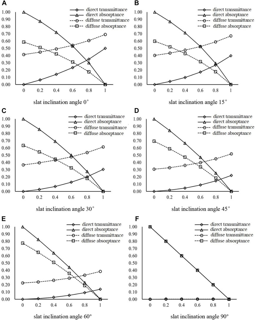
FIGURE 11. Effect of different slat materials on the optical performance of PCM blind. (A) slat inclination angle 0° (B) slat inclination angle 15° (C) slat inclination angle 30° (D) slat inclination angle 45° (E) slat inclination angle 60° (F) slat inclination angle 90°.
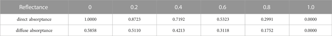
TABLE 6. Summary of direct absorptance and diffuse absorptance, for different reflectance of slat surface.
When the slat inclination angle is 45° and the reflectance of the slat is 0, meaning the slat is a blackbody, the direct radiation passing through the blind gap is nearly 0, with a direct absorptance of 1.0000 and a diffuse absorptance of 0.5858. This is mainly because the diffuse radiation is independent of the angle of solar incidence. For the diffuse-to-diffuse performance, when the slat’s reflectance is 0, a significant portion of the ground diffused radiation can directly pass through the blind gap, keeping the ground diffuse-to-diffuse transmittance at a high value. Similarly, as the surface reflectance of the blind increases, the reflectance of the blind system decreases.
At different slat inclination angles, the optical coefficients of direct radiation and diffuse radiation gradually converge as presented in Figure 11F and Table 7.
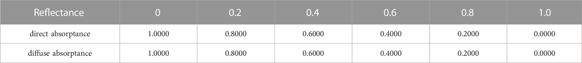
TABLE 7. Summary of direct absorptance and direct transmittance, for different reflectance of slat surface.
The direct absorptance and diffuse absorptance coincide completely. When the ratio of slat distance to slat width is 1:1 and the slat inclination angle is 90°, the blind is equivalent to a flat plate, and the comprehensive optical coefficient of the PCM blind is consistent with the optical coefficient of the slat surface, which confirms our understanding. Based on the information in Figure 11, the direct absorptance is always greater than the diffuse absorptance regardless of the ratio of slat distance to slat width, and the direct transmittance is smaller than the diffuse transmittance.
The above results indicate that at the same solar incidence angle, the direct transmittance gradually decreases with the increase of the slat inclination angle, while the direct absorptance first increases and then decreases, and the diffuse absorptance gradually increases. The direct absorptance decreases slowly at first with the increase of the ratio of slat distance to slat width, and then drops sharply when it reaches a critical point (ratio of slat distance to slat width is 1.0). Regardless of the ratio of slat distance to slat width, the direct absorptance is always greater than the diffuse absorptance, while the direct transmittance is less than the diffuse transmittance. The direct absorptance and diffuse absorptance of the blinds decrease as the reflectance of the blinds’ surface material increases. These findings provide a reference for selecting phase change materials and estimating component consumption.
A solar radiation model for a PCM blind in a DSF system was established by analyzing the optical path of sunlight through the blind. The impact of solar incidence angle, slat inclination angle, the ratio of slat distance to slat width, and slat surface material on the optical coefficients of the blind system was analyzed. The following conclusions were drawn.
1) Slat inclination angle significantly affects diffuse absorptance and diffuse transmittance, while solar incidence angle has little impact. Diffuse absorptance gradually increases with increasing slat inclination angle, reaching a peak at 90°, while diffuse transmittance decreases.
2) Direct absorptance and direct transmittance are closely related to solar incidence angle with the same angle of slat inclination. Direct transmittance decreases with increasing slat inclination angle. Direct absorptance first increases, peaking at 60°–75°, and then slowly decreases.
3) Assuming that the slat inclination angle is constant, the direct absorptance and direct transmittance show significant variations as the solar incidence angle increases. The direct transmittance consistently decreases with increasing solar incidence angle. When the solar incidence angle is less than 45°, the direct absorptance gradually increases before slowly decreasing to a stable value. When the solar incidence angle is greater than 45°, the direct absorptance initially decreases and approaches the absorptance of the material itself with increasing solar incidence angle.
4) The optical coefficient of the PCM blind is related to the angle of the blind and the ratio of slat distance to slat width. The smaller the slat inclination angle, the more noticeable the difference in absorptance or transmittance of direct/diffuse solar radiation. As the ratio of slat distance to slat width increases, the direct absorptance decreases.
5) The direct absorptance and diffuse absorptance of the blind decreases with increasing reflectance of the blind surface material. Regardless of changes in the ratio of slat distance to slat width, direct absorptance is always greater than diffuse absorptance, while direct transmittance is less than diffuse transmittance.
The original contributions presented in the study are included in the article/supplementary material, further inquiries can be directed to the corresponding author.
YL: Supervision, conceptualization and writing. YP: Writing and theoretical calculation .HJ: Theoretical model development and model validation .SF: Writing and editing.
Sponsored by Shanghai Sailing Program 20YF1432000 and National Natural Science Foundation of China 52008245.
The authors declare that the research was conducted in the absence of any commercial or financial relationships that could be construed as a potential conflict of interest.
All claims expressed in this article are solely those of the authors and do not necessarily represent those of their affiliated organizations, or those of the publisher, the editors and the reviewers. Any product that may be evaluated in this article, or claim that may be made by its manufacturer, is not guaranteed or endorsed by the publisher.
Balali, A., Yunusa-Kaltungo, A., and Edwards, R. (2023). A systematic review of passive energy consumption optimisation strategy selection for buildings through multiple criteria decision-making techniques. Renew. Sustain. Energy Rev. 171, 113013. doi:10.1016/j.rser.2022.113013
Code for Thermal, Calculation specification for thermal performance of windows, doors and glass curtain-walls. Tamil Nadu, India: China Architecture & Building Press.
Colgan, J. D. (2006). IEA. Energy Efficiency: Buildings. Available at: https://www.iea.org/reports/energy-efficiency-2022.
de Gracia, A., Navarro, L., Castell, A., Ruiz-Pardo, Á., Alvárez, S., and Cabeza, L. F. (2013). Experimental study of a ventilated facade with PCM during winter period. Energy Build. 583, 324–332. doi:10.1016/j.enbuild.2012.10.026
Duffie, J. A., and Beckman, W. A. (1991). Solar Engineering of Thermal Processes. 2nd. New York, NY, USA: John Wiley and Sons.
Elarga, H., Goia, F., Zarrella, A., Dal Monte, A., and Benini, E. (2016). Thermal and electrical performance of an integrated PV-PCM system in double skin façades: A numerical study. Sol. Energy 136, 112–124. doi:10.1016/j.solener.2016.06.074
Gloria Gomes, M., Rodrigues, A. M., and Bogas, J. A. (2012). Numerical and experimental study of the optical properties of Venetian blinds. Build. Phys. 36 (1), 7–34. doi:10.1177/1744259112444022
Li, Y., Darkwa, J., Kokogiannakis, G., and Su, W. (2019). Phase change material blind system for double skin faade integration: System development and thermal performance evaluation. Appl. Energy 252. doi:10.1016/j.apenergy.2019.113376
Liu, C., Zhang, G., Arıcı, M., Bian, J., and Li, D. (2019). Thermal performance of non-ventilated multilayer glazing facades filled with phase change material. Sol. Energy 177, 464–470. doi:10.1016/j.solener.2018.11.044
Liu, C., Li, D., Shi, W., Yuan, L., and Liu, Y. (2017). Analysis of optical and thermal properties of semi-transparent PCM-glazed unit. Acta Energiae Solaris Sinica 38 (2), 416–422. doi:10.19912/j.0254-0096.2017.02.018
Ma, J. (2003). Analysis of Light Transmittance of Sunshade Structure Outside Windows in Guangzhou Area. Guangzhou, China: South China University of Technology.
Mirkovic, M., and Alawadi, K. (2017). The effect of urban density on energy consumption and solar gains: The study of abu dhabi's neighborhood. Energy Procedia 143, 19–21. doi:10.1016/j.egypro.2017.12.684
Mitalas, (1962). Absorption and transmission of thermal radiation by single and double windows. http://web.mit.edu/parmstr/Public/NRCan/rp173.pdf Research paper.
Mousavi Baygi, S. R., and Sadrameli, S. M. (2018). Thermal management of photovoltaic solar cells using polyethylene glycol 1000 (PEG1000) as a phase change material. Therm. Sci. Eng. Prog., 5405–5411.
Pasquay, T. (2004). Natural ventilation in high-rise buildings with double facades, saving or waste of energy. Energy Build. 36, 381–389. doi:10.1016/j.enbuild.2004.01.018
Pfrommer, P., Lomas, K. J., and Kupke, C. H. R. (1996). Solar radiation transport through slat-type blinds: A new model and its application for thermal simulation of buildings. Sol. Energy 57 (2), 77–91. doi:10.1016/s0038-092x(96)00063-1
Pfrommer, P., Lomas, K. J., Seale, C., and Kupke, C. (1995). The radiation transfer through coated and tinted glazing. Sol. Energy 54 (5), 287–299. doi:10.1016/0038-092x(94)00132-w
Rubin, M., von Rottkay, K., and Powles, R. (2006). Window optics. Sol. Energy 62, 1–12. doi:10.1016/S0038-092X(98)00010-3
Saelens, D., Roels, S., and Hens, H. (2004). The inlet temperature as a boundary condition for multiple-skin facade modelling. Energy Build. 36, 825–835. doi:10.1016/j.enbuild.2004.01.005
Sawadogo, M., Duquesne, M., Belarbi, R., Hamami, A. E. A., and Godin, A. (2021). Review on the integration of phase change materials in building envelopes for passive latent heat storage. Energies 11, 14. doi:10.3390/app11199305
Tanimoto, J., and Kimura, K. (1997). Simulation study on an air flow window system with an integrated roll screen. Energy Build. 26, 317–325. doi:10.1016/s0378-7788(97)00012-1
Keywords: double skin facade (DSF), phase change material (PCM), optical properties, solar radiation, theoretical study
Citation: Li Y, Peng Y, Jing H and Fu S (2023) Theoretical study on the optical properties of a phase change material blind in a double skin facade system. Front. Built Environ. 9:1134590. doi: 10.3389/fbuil.2023.1134590
Received: 30 December 2022; Accepted: 27 February 2023;
Published: 20 March 2023.
Edited by:
Giridharan Renganathan, University of Kent, United KingdomReviewed by:
Roberto Alonso González-Lezcano, CEU San Pablo University, SpainCopyright © 2023 Li, Peng, Jing and Fu. This is an open-access article distributed under the terms of the Creative Commons Attribution License (CC BY). The use, distribution or reproduction in other forums is permitted, provided the original author(s) and the copyright owner(s) are credited and that the original publication in this journal is cited, in accordance with accepted academic practice. No use, distribution or reproduction is permitted which does not comply with these terms.
*Correspondence: Yilin Li, eWlsaW4ubGlAdXNzdC5lZHUuY24=
Disclaimer: All claims expressed in this article are solely those of the authors and do not necessarily represent those of their affiliated organizations, or those of the publisher, the editors and the reviewers. Any product that may be evaluated in this article or claim that may be made by its manufacturer is not guaranteed or endorsed by the publisher.
Research integrity at Frontiers
Learn more about the work of our research integrity team to safeguard the quality of each article we publish.