 Gloria Terenzi
 Stefano Sorace
 Elena Fuso2
94% of researchers rate our articles as excellent or good
Learn more about the work of our research integrity team to safeguard the quality of each article we publish.
Find out more
ORIGINAL RESEARCH article
Front. Built Environ., 26 January 2023
Sec. Earthquake Engineering
Volume 9 - 2023 | https://doi.org/10.3389/fbuil.2023.1114349
This article is part of the Research TopicEnergy dissipation devices and vibration-control systems for structures and infrastructures to mitigate damages under different hazardsView all 6 articles
Added Damping and Stiffness (ADAS) steel dissipators are among the most classical devices installed in dissipative bracing systems for the advanced seismic retrofit of frame buildings. An energy-based sizing procedure is formulated in this study for this class of dampers, where the total number of constituting plates is directly related, without iterative steps, to the supplementary damping energy required to jointly reduce stress states in structural members and storey drifts. The stiffening effects of the dissipative braces are expressly controlled, so as to compensate for the increase in storey shears induced by their incorporation in the frame skeleton. The sizing procedure is demonstratively applied to the retrofit design of a 6-storey reinforced concrete building, to explicate and discuss the use of its analytical relations and relevant limitations in practice. The evaluation of the seismic performance of the structure in retrofitted conditions allows comparing the response of the dissipative bracing system with the hypotheses formulated at the sizing stage.
Seismic retrofit strategies of frame structures are quickly evolving, and several significant contributions have been recently offered in terms of design approaches and modelling (Marano et al., 2007; Greco and Marano, 2016; Di Trapani et al., 2020; Aloisio et al., 2022), as well as of implementation of innovative protection techniques or upgrade of existing ones (Aloisio et al., 2022; Boggian et al., 2022; Lu and Phillips, 2022; Zhao et al., 2022).
Among the strategies based on the incorporation of supplementary damping devices, those making use of Added Damping and Stiffness (ADAS) steel dissipators have a well-established tradition (Bergman and Goel, 1987; Whittaker et al., 1991; Aiken et al., 1993; Martinez-Romero, 1993; Tsai et al., 1993; Dargush and Soong, 1995), updated to recent developments too (Mazza, 2014; Teruna, 2015; Moghaddasi and Namazi, 2016; Sorace et al., 2016; Mohammadi et al., 2017; Mazza and Imbrogno, 2019; Shojaeifar et al., 2020; Gandelli et al., 2021; Khoshkalam et al., 2022). This is a consequence of the plain working principle of these devices, based on the elastic-plastic behaviour of the constituting plates, as well as of their relatively easy installation. In spite of this, the design of ADAS dampers is not an easy task, as it requires a proper balance between the addition of energy dissipation and horizontal translational stiffness. The former allows remarkably reducing plastic demand on structural members. The latter is always beneficial in terms of lateral displacements but, as long as the dampers respond elastically, can cause a significant increase in base and storey shears, and thus in the stress states of the frame skeleton elements and foundations.
In view of this, an energy-based preliminary sizing criterion of ADAS dampers was proposed by the first two authors of this article (Sorace et al., 2016), aimed at achieving a joint control of stress states and displacements. According to this criterion, typically framed within a performance-based design approach (SEAOC, 1995; Priestley, 1997; Priestley and Calvi, 1997; Fardis. 2007; Priestley et al., 2007), the total number of plates is tentatively fixed by: 1) pre-estimating the energy dissipation capable of providing a target drop of base shear in retrofitted conditions; 2) computing the energy dissipation capacity by assuming a maximum displacement of the dissipators calibrated on a target reduction of storey drifts. By expanding and developing this method, a new sizing procedure is formulated in this article, where the energy dissipation capacity of the dampers is evaluated by expressly compensating the bracing-related increase of base shear, caused by the increase in lateral stiffness of the structure.
The distinguishing features of the procedure, as compared to other existing methods, can be synthesized in the two following points: 1) it provides a quick estimate of the energy demand on the protective system, based on simple analytical relations making use of spectral displacement, velocity, and pseudo-acceleration ordinates; 2) it is intrinsically not iterative, as these relations are linear.
Concerning the application of the procedure, the use of spectral quantities produces the best approximation for structures characterized by first translational modes along the two coordinate axes in plan with associated modal masses constituting a predominant portion of the total seismic masses. This condition is basically met by structures with a rather regular geometry in plan and elevation. However, in order to effectively apply the sizing procedure to irregular structures too, a modulating coefficient of the energy dissipation demand is included to compensate for higher translational modes and/or plan torsion response effects.
The formulation of the sizing criterion is presented in Section 2. A demonstrative application is offered in Section 3, Section 4, concerning the retrofit design of a representative case study, i.e., a 6-storey residential building with reinforced concrete (RC) structure situated in L’Aquila, Abruzzo, Italy. Based on the results of a seismic assessment analysis initially carried out on the building (Section 3), the application of the procedure is explicated and discussed in detail in Section 4.1, Section 4.2. The performance of the structure in retrofitted conditions is finally evaluated (Section 4.3), to compare the response of the designed ADAS-equipped dissipative bracing system with the hypotheses formulated at the sizing stage.
ADAS dissipators consist of an assembly of multiple X-shaped or isosceles triangle-shaped (in which case they are named T-ADAS) steel plates mounted in parallel, which act as short cantilever beams with cross section linearly varying along the span, similarly to the bending moment diagram.
Figure 1 shows the drawing of a T-ADAS damper, the geometry of a constituting plate and the P (t)–d (t) force–displacement hysteretic response cycle of the latter, idealized with a bilinear hardening shape. The mechanical parameters governing the cycle are: Py, Pu = yielding and ultimate force, dy, du = yielding and ultimate displacement, all intended with positive and negative sign, ke, kp = stiffness of the elastic and post-elastic response branch, and γ = kp/ke = strain hardening ratio of the post-elastic branch, normally assumed as equal to 0.03 (Dargush and Soong, 1995).
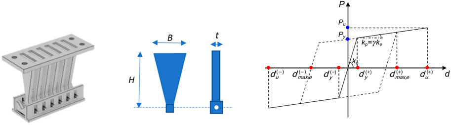
FIGURE 1. Drawing of a T-ADAS damper, and geometry and idealized horizontal force-displacement response cycle of a constituting plate.
Based on the geometric symbols in Figure 1, and named fy the yielding stress of steel, the expressions of the response cycle parameters are as follows:
The preliminary sizing procedure of the dampers proposed in this study is aimed at evaluating the number of plates to be installed in the bracing system, npl, starting from a quick estimation of the energy dissipation capacity by which a pre-established reduction of lateral displacements and base shear of the structure is attained. For frame buildings with a substantially regular geometry in plan and elevation, this estimation is carried out in terms of spectral quantities, by referring to the periods of the first translational modes along the two coordinate axes in plan (which a predominant portion of modal masses is associated with, in the above-mentioned hypothesis of approximate regularity). Both in current and retrofitted conditions, these periods are assumed to be included in the wide period interval of the normative response spectra that corresponds to the constant pseudo-velocity branch, identified by the periods limits TC and TD, where the fundamental vibration periods of low rise through mid-to-high rise RC frame structures are situated.
For both axes in plan, X and Y, of the reference Cartesian coordinate system assumed in the analysis, named TIN the fundamental period of the structure in current state, the procedure starts by fixing a tentative reduction, ΔSD-, in the spectral displacement computed for TIN. Consistently with the first mode-based quick estimation of seismic response adopted here, the difference between SD (TIN) and ΔSD- is put as equal to an assumed target value of the top lateral displacement of the structure, Dtop,targ:
from which ΔSD- derives:
Then, named SV,cost the value of the horizontal branch of the pseudo-velocity spectrum, the period in retrofitted conditions, TFIN, given by the difference between TIN and the period reduction ΔT corresponding to ΔSD-, can be evaluated as follows:
As illustrated in Figure 2, a ΔSA+ rise in pseudo-acceleration is generated when passing from TIN to TFIN, as a consequence of the increase in lateral stiffness induced by the incorporation of the dissipative bracing system. Therefore, its supplementary damping contribution must contextually generate a drop in the spectral ordinate, ΔSA-,diss, so as to decrease base shear—or, when deemed sufficient, to limit its growth—as compared to current conditions. Consistently, ΔSA-,diss is tentatively fixed in proportion to ΔSA+, by means of an energy dissipation demand coefficient, med, to be calibrated on the design objective(s) fixed in terms of base shear. This condition is expressed as:
where med > 1 targets to reduce both lateral displacements and base shear, whereas med ≤ 1 only the former. It can be noted that a moderate increase in base shear can be often accepted, since a significant portion of storey shears is absorbed, as axial forces, by the diagonal trusses of the bracing system. This allows remarkably reducing bending moments and shears in beams and columns, as targeted in the design, only causing an increase of axial forces in the columns belonging to the vertical alignments where the system is placed, as well as of the stress states in the underlying portions of the foundations. Therefore, in order to prevent an excessive addition of supplementary damping, med values equal to or slightly greater than 1 (i.e., equal to 1.1–1.2), and in some cases even slightly smaller than 1, can be adopted, especially for regular structures. At the same time, greater med values are normally needed for irregular structures, to compensate for possible significant contributions of the higher translational modes, and/or plan torsion response effects related to the rotational modes around the vertical axis of the reference coordinate system. Furthermore, med values greater than 1 are normally needed for frame structures, with RC or steel skeleton, characterized by rather high fundamental vibration periods (e.g., greater than 1.5 s), since in these cases a greater increase in lateral stiffness—and thus in base shear—is induced by the stiffening action of the bracing system.
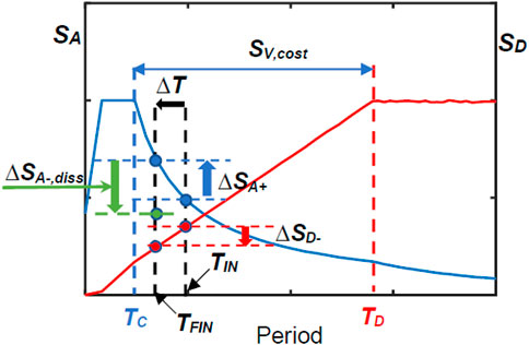
FIGURE 2. Spectral quantities involved in the sizing procedure.
The supplementary damping-related reduction in base shear, ΔV, is obtained by multiplying ΔSA-,diss by the seismic mass M of the building. Hence, the tentative energy dissipation capacity to be assigned to the protective system is computed as:
By separately applying relations (Eq. 7) through (Eq. 11) for the X and Y axes, the corresponding energy dissipation capacities, Ed,X, Ed,Y, are obtained. Then, the total numbers of plates of the sets of ADAS dampers to be installed in X and Y, np,X, np,Y, are evaluated by dividing Ed,X, Ed,Y by the estimated total energy dissipated by each plate, Ed,p,t, under the input ground motions assumed in the design analyses. Ed,p,t is calculated by computing, at a first step, the Ed,p,c energy dissipated by a plate in a cycle bounded by the maximum estimated (positive or negative) displacement, dmax,e (symbolically indicated in the graph of Figure 1 too), given by:
Then, Ed,p,t is obtained by summing to Ed,p,c the energy dissipated in all remaining cycles with smaller amplitudes, Ed,p,r. Ed,p,r was evaluated to be about 10 times greater than Ed,p,c in a recent extensive numerical research (Gandelli et al., 2021). At the same time, a similar value was preliminarily estimated in this study for simpler frame structures than the case study one, not reported here for brevity’s sake, by extending the findings of a previous study of the authors carried out for a special infrastructure (Sorace et al., 2016). Based on this approximate Ed,p,r value, the tentative evaluation of Ed,p,t results as follows:
Thus, np,X, np,Y are finally evaluated as follows:
For the practical application of Eqs 12, 13, dmax,e must be preliminarily quantified. This can be done by relating it to the maximum inter-storey drift (IDm) of the structure, and fixing a target design value for the latter, IDm,t. By considering that the supporting diagonal braces of the ADAS devices are remarkably rigid at the horizontal translation, and thus lateral displacements are mainly determined by the plastic deformation of the dissipators (Sorace et al., 2016), at the sizing stage dmax,e can be approximately assumed to coincide with IDm,t.
The latter is calibrated on the specific characteristics of each case study and the severity of the basic earthquake level considered in the performance assessment analysis (formally defined in the next section). By way of example, in order to limit damage to a fully repairable level in masonry infill and partition panels of RC frame buildings, when they are built in contact with the structural members, named IH the inter-storey height, IDm,t could be tentatively put as equal to 0.5% of IH, i.e., the limit fixed by the Italian Technical Standards (Italian Ministry of Infrastructure and Transport, 2018) as basic requirement for the attainment of the Immediate Occupancy (IO) performance level. The same drift limitation is assumed by internationally prominent performance-based seismic Standards and Guidelines, among which SEAOC Vision 2000 (SEAOC, 1995), FEMA 356 (ASCE, 2000), ATC 58-2 (ATC, 2003), ASCE/SEI 41 (ASCE, 2017), as repairability threshold for unreinforced masonry infill and partition walls.
The examined case study is a residential building, located in L’Aquila, Abruzzo, Italy, designed in compliance with the 1986 edition of the Italian Seismic Standards, where a maximum pseudo-acceleration spectral ordinate of 0.07 g (g = acceleration of gravity) was prescribed for the corresponding seismic zone. As illustrated in Figure 3, referred to the ground storey, the building has a 21.05 × 11.45 m2 sized rectangular plan, with the first side parallel to the X axis and the second one to the Y axis of the assumed Cartesian reference system. The building has six above-ground storeys in elevation, with inter-storey heights equal to 3.4 m for the ground storey and 3.04 m for the remaining ones.
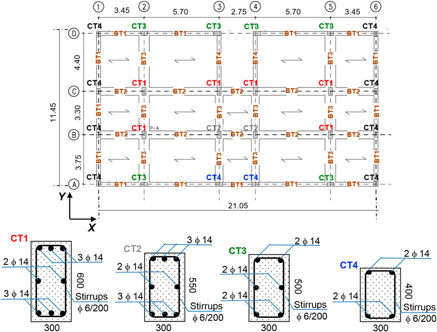
FIGURE 3. Structural plan of the building (ground storey, dimensions in meters) and cross sections of columns CT1 through CT4 (dimensions in millimeters).
The structure is constituted by a RC frame skeleton. Columns are of five types, named CT1 through CT5, having the following cross sections and steel reinforcing bars: CT1—300 × 600 (side parallel to X×side parallel to Y) mm2, 8ø14; CT2—300 × 550 mm2, 8ø14; CT3—500 × 300 mm2, 6ø14; CT4—300 × 400 mm2, 4ø14; and CT5—300 × 300 mm2, 4ø12. The transversal reinforcement is constituted by 200 mm-spaced ø6 stirrups for all columns. By way of example, the column types–vertical fixed lines association on the ground storey is the following (Figure 3): CT1—2/B, 5/B, 2/C, 3/C, 4/C, 5/C (columns with acronym printed in red); CT2—3/B, 4/B, 3/D, 4/D (grey); CT3—2/A, 3/A, 4/A, 5/A, 2/D, 5/D (green); CT4—1/A, 6/A, 1/B, 6/B, 1/C, 6/C, 1/D, 6/D (black). The cross sections of columns CT1 through CT4 are also drawn in Figure 3. The association for the entire structure is recapitulated in Table 1. On all storeys, perimeter beams (named BT1 in Figure 3) have out-of-depth section sized 300 × 500 (base×height) mm2, with constant reinforcement given by 3ø16 top bars and 2ø16 bottom bars, and 200 mm-spaced ø6 stirrups; internal beams parallel to X (BT2) have in-depth sections sized 600 × 250 mm2, with a maximum of 8ø16 top bars and 6ø16 bottom bars, and ø6 stirrups with spacing varying from 70 mm to 200 mm; internal beams parallel to Y (BT3) have in-depth sections sized 800 × 250 mm2, with a maximum of 8ø20 top bars and 5ø20 bottom bars, and ø6 stirrups with spacing varying from 150 mm to 200 mm. The flights of stairs, embedded in the 3/C-3/D and 4/C-4/D alignments in plan, are borne by inclined beams (BT4) having 300 × 400 mm2 section, with constant 4ø14 top and 4ø14 bottom bars, and 200 mm-spaced ø6 stirrups. The foundations are constituted by a mesh of inverse T-shaped RC beams. Their base sections are 2,600 mm-wide in Y direction and 1,600 mm-wide in X, with 1,200 mm (Y) and 800 (X) mm-high webs, and 600 mm (Y) and 400 mm (X) mm-high and 700 (X and Y) mm-wide webs. Floors are made of 200 mm-high RC joists, parallel to X axis, interposed clay lug bricks, and a 50 mm thick upper RC slab. Both for the elevation and foundation structures, reinforcing bars are made of FeB44k steel, with yield stress and tensile strength values greater than 430 MPa and 540 MPa, respectively; and concrete is 25/30 class, with cylindrical and cubic compressive strength of 25 MPa and 30 MPa, respectively. The dead and live loads assumed in the analyses are as follows: 5 kN/m2 (dead) and 2 kN/m2 (live) on first through fifth floor; 3.8 kN/m2 and 1.2 kN/m2 on sixth (roof) floor. The live loads on the stairwell are equal to 4 kN/m2.
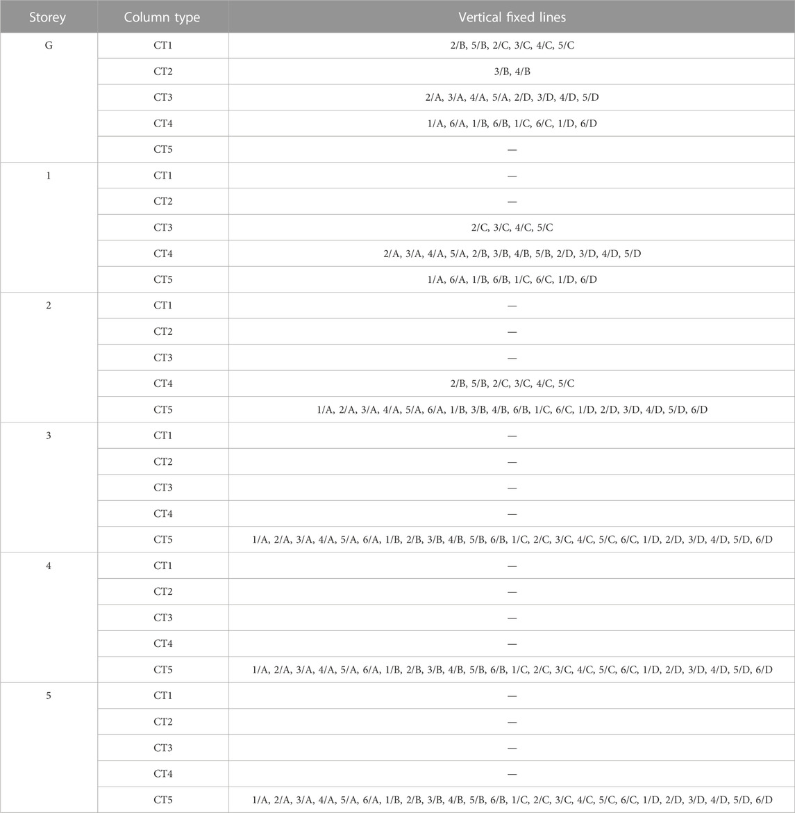
TABLE 1. Column sections.
A view of the finite element model of the structure, generated by SAP2000NL software (CSI, 2022), is displayed in Figure 4, where the Cartesian reference system is traced out too. Elastic frame elements were used to model columns and beams, consistently with the choice of evaluating the effectiveness of the sizing procedure within a conventional elastic analysis approach, where seismic performance in retrofitted conditions is assessed in terms of reductions of stress states in structural members and inter-storey drifts, as compared to current state. A Rayleigh-type inherent viscous damping was assigned to the finite element structural model.
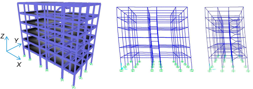
FIGURE 4. Views of the finite element model of the structure and the first mode shapes in X and Y.
A modal analysis carried out by this model highlighted two main translational modes in current state, whose shapes are plotted in Figure 4 too, with vibration period, TIN, equal to 1.21 s along X and 1.18 s along Y, and effective modal masses of 86.4% and 85.7%, respectively, of the total seismic mass M of the building, equal to 1,675 kN/g. Both values are greater than the 85% threshold representing the minimum percentile fraction required by the Italian Technical Standards to develop a modal superposition analysis. Period and effective mass of the first rotational mode around the vertical axis Z are equal to 1.05 s and 81.1%, respectively. As a consequence of the substantial structural regularity in plan and elevation, a total of nine modes is needed to activate summed modal masses greater than 90% of M along X, Y, and around Z, and a total of eighteen modes to attain over than 99% of M.
The seismic assessment study of the building was developed via time-history analysis by using as input a set of seven groups of three accelerograms. For each group, one accelerogram was applied in X direction, one in Y, and one in Z. The artificial ground motions were generated from the elastic pseudo-acceleration response spectra at linear viscous damping ratio of 0.05 assumed by the current Italian Technical Standards for L’Aquila, drawn in Figure 5. The three spectral graphs for the horizontal components and the three graphs for the vertical one are referred to the Serviceability Design Earthquake (SDE, characterized by 63% probability of being exceeded over the reference structural lifespan, VR), Basic Design Earthquake (BDE, with 10%/VR probability) and Maximum Considered Earthquake (MCE, with 5%/VR probability) hazard levels, for C-type (i.e., medium-dense sand) soil and T1-type (i.e., flat surface) topographic category. The corresponding peak ground acceleration values are: 0.156 g (SDE), 0.347 g (BDE), and 0.407 g (MCE), for the horizontal components; 0.045 g (SDE), 0.180 g (BDE), and 0.261 g (MCE), for the vertical one.
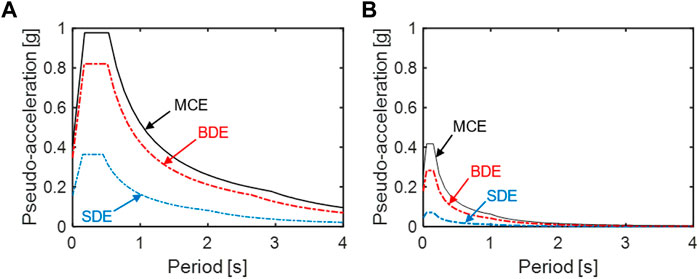
FIGURE 5. Horizontal (A) and vertical (B) pseudo-acceleration elastic response spectra for L’Aquila—SDE, BDE, and MCE hazard levels.
The results of the analysis in current conditions are synthesized in the top halves of Tables 2, 3. Table 2 reports the maximum storey shears along the two axes in plan, Vm,X and Vm,Y, and their ratios, ρV,X and ρV,Y, to relevant strength values, VR,X and VR,Y (where VR,X, VR,Y are given by the sums of the shear strength values of the ground storey columns). Table 3 lists the maximum inter-storey drifts, IDm,X, IDm,Y, and their ratios, ρID,X and ρID,Y, to IH.
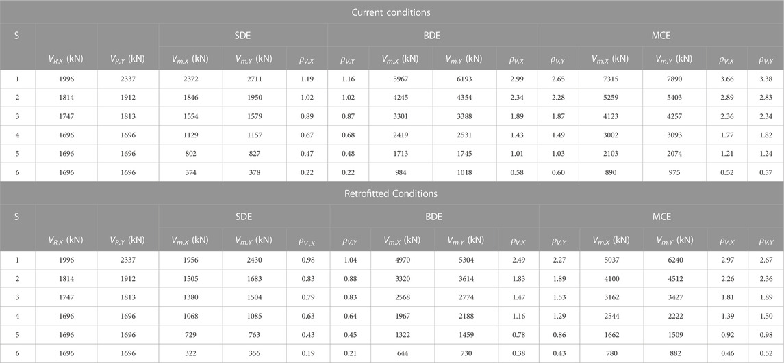
TABLE 2. Vm,X, Vm,Y maximum storey shears, and corresponding ρV,X, ρV,Y ratios to relevant VR,X, VR,Y strength values, in current and retrofitted conditions.
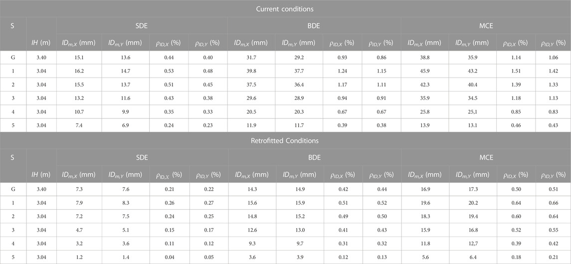
TABLE 3. IDm,X, IDm,Y maximum inter-storey drifts, and corresponding ρid,X, ρid,Y ratios to relevant IH inter-storey heights, in current and retrofitted conditions.
As shown in Table 2, ρs,X, ρs,Y ratios greater than 1 are found for the first two, four and five storeys at the SDE, BDE, and MCE, respectively, reaching values of 1.19, 2.99, 3.66 (ρs,X), and 1.16, 2.65, 3.38 (ρs,Y) on the ground storey. Values notably below 1 come out for the top storey up to the MCE. The corresponding results in terms of stress states in the structural members highlight 22%, 72%, and 81% of columns, and 18%, 68%, and 76% of beams in unsafe conditions at the SDE, BDE, and MCE, respectively. By way of example of these results, the M1–M2 biaxial moment interaction curves obtained at the BDE for the columns belonging to the 2/B vertical fixed line—where M1, M2 are the bending moments around the two local reference axes of the column cross section—are plotted in Figure 6. Except for the top storey, these curves remarkably overcome the boundaries of the axial force-biaxial moment safe domains, traced out for comparison in the same graphs, reaching maximum values of the demand/capacity ratio equal to 2.23 (ground storey), 1.76 (first), 1.98 (second), 1.84 (third), and 1.65 (fourth).
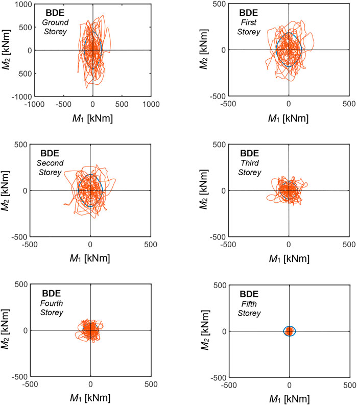
FIGURE 6. M1–M2 biaxial moment interaction curves (red lines) for the columns belonging to the 3/B vertical fixed line obtained from the most demanding BDE-scaled group of input accelerograms, and relevant safe domains (blue lines).
Table 3 highlights that the ρID,X ratios at the SDE are slightly greater than the above-mentioned IO performance level-related 0.5% IH limit (ρID,X = 0.53%, 0.51% on the first and second storey, respectively), assessing a satisfactory performance in terms of drifts for this earthquake level. At the same time, ρID,X and ρID,Y ratios slightly smaller than 1 are observed at the BDE on the ground and third storey, and greater than 1 on the first and second storey, reaching ρID,X peak values of 1.24% (first) and 1.17% (second), and ρID,Y peak values of 1.15% (first) and 1.11% (second), implicitly assessing irreparable damage conditions of infills and partitions at these storeys. At the MCE, ρID,X and ρID,Y values greater than 1 are observed on the four lower storeys, with maximum values of 1.51 (ρID,X) and 1.42 (ρID,Y) on the first storey.
By referring to the nomenclature in Figure 1, the retrofit intervention on the case study building was designed by assuming the following classical (Martinez-Romero, 1993; Tsai et al., 1993; Dargush and Soong 1995) geometric sizes of the plates: H = 150 mm, t = 15 mm, and B = 75 mm. The constituting steel is type S275, with yield stress and tensile strength equal to 275 N/mm2 and 430 N/mm2, respectively. For these geometrical and mechanical characteristics, the following values of the yielding force and displacement of a plate, to be introduced in relation (12), are obtained by means of expressions 1) and 2): Py = 5.156 kN, dy = 1.96 mm.
According to the approach followed in recent multi-objective sizing procedures of dampers for the seismic retrofit of frame buildings (Lavan and Dargush, 2009; Akehashi and Takewaki, 2021; De Domenico and Hajirasouliha, 2021), the design of the protective system is carried out for the BDE hazard level, with checks extended to the SDE and the MCE in the final verification analysis. In order to apply the sizing criterion presented in Section 2, the dmax,e maximum plate displacement, to be introduced in Eq. 12 too, is put as equal to IDm,t = 0.5% IH, by referring to the greater inter-storey height, equal to 3.4 m. Thus, the following value results: dmax,e = (0.005 ⋅ 3,400) mm = 17 mm. Consistently with this assumption, Dtop,targ is put as equal to 0.5% of the total height of the structure (18.6 m), which yields: Dtop,targ = (0.005 ⋅ 18,600) mm = 93 mm, both in X and Y. Moreover, by considering the substantial regularity of the case study structure, med = 1 is tentatively considered in (10).
Based on these hypotheses, the application of the criterion is separately detailed below for the two axes (thus, lower indexes X, Y are added to all quantities and symbols introduced in the previous sections).
TIN,X = 1.21 s
SD,X(TIN,X) = 159.4 mm
SA,X(TIN,X) = 0.349 g
SV,cost = 665.7 mm/s
Dtop,targ = 93 mm
ΔSD-,X = SD,X(TIN,X)—Dtop,targ = 66.4 mm
By (9): TFIN,X = 0.584 s
SA,X(TFIN,X) = 0.723 g
ΔSA+,X = SA,X(TFIN,X)—SA,X(TIN,X) = 0.374 g
By (10), for med = 1: ΔSA-,diss,X = ΔSA+,X = 0.374 g
By (11), for M = 1675 kN/g: Ed,X = (4 ⋅ 1675 ⋅ 9.81 ⋅ 0.374 ⋅ 0.0664) kJ = 1632 kJ
By (12), for dmax,e = 17 mm: Ed,p,c,X = [2 ⋅ 5.156 ⋅ 2 ⋅ (17—1.96)] J = 310 J = 0.31 kJ
By (13): Ed,p,t,X = (11 ⋅ 0.31) kJ = 3.41 kJ
By (14a): np,X = Ed,X/Ed,p,t,X = 479
TIN,Y = 1.18 s
SD,Y(TIN,Y) = 155.4 mm
SA,Y(TIN,Y) = 0.358 g
SV,cost = 665.7 mm/s
Dtop,targ = 93 mm
ΔSD-,Y = SD,Y(TIN,Y)—Dtop,targ = 62.4 mm
By (9): TFIN,Y = 0.591 s
SA,Y(TFIN,Y) = 0.719 g
ΔSA+,Y = SA,Y(TFIN,Y)—SA,Y(TIN,Y) = 0.361 g
By (10), for med = 1: ΔSA-,diss,Y = ΔSA+,Y = 0.361 g
By (11), for M = 1675 kN/g: Ed,Y = (4 ⋅ 1675 ⋅ 9.81 ⋅ 0.361 ⋅ 0.0624) kJ = 1481 kJ
By (12), for dmax,e = 17 mm: Ed,p,c,Y = [2 ⋅ 5.156 ⋅ 2 ⋅ (17—1.96)] J = 310 J = 0.31 kJ
By (13): Ed,p,t,Y = (11 ⋅ 0.31) kJ = 3.41 kJ
By (14b): np,Y = Ed,Y/Ed,p,t,Y = 434
It is noted that the SD,X(TIN,X) = 159.4 mm and SD,Y(TIN,Y) = 155.4 mm spectral displacements are 6.8% and 5.4% smaller than the sums of the IDm,X and IDm,Y values derived from the time-history analyses at the BDE, listed in Table 2, equal to 171 mm and 164.2 mm, respectively. At the same time, by multiplying the SA,X(TIN,X) = 0.349 g and SA,Y(TIN,Y) = 0.358 g spectral accelerations by g and the seismic mass M, the following base shear values are obtained: SA,X(TIN,X) ⋅ g ⋅ M = 5736 kN, SA,Y(TIN,Y) ⋅ g ⋅ M = 5884 kN, which are 3.9% and 5% smaller than the corresponding Vm,X = 5967 kN, Vm,Y = 6,193 kN values reported in Table 2 for the ground storey at the BDE. These small differences are related to the higher mode contributions to the time-history response of the structure, as compared to the first mode-based spectral evaluation assumed in the preliminary sizing procedure.
The similar total numbers of plates in X (479) and Y (434) obtained from its application is a consequence of the similar modal properties of the structure in the two directions. In order to preserve this similarity also in retrofitted conditions, an equal design number of plates in X and Y, npd,X, npd,Y, is adopted as final output of the procedure, nearly equal to the mean of np,X and np,Y, namely npd,X = npd,Y = 464.
Based on these total numbers of plates, the final design of the protective system is carried out by: 1) selecting the vertical alignments where the dissipative braces are to be inserted, and 2) distributing the plates in elevation along the storeys. In order to minimize the architectural impact of the intervention on the interiors of the building (Martinez-Romero, 1993; Mazza, 2014), as well as to increase the torsional stiffness of the building in plan (Terenzi et al., 2020; Kookalani et al., 2022), the following 16 (8 in X and 8 in Y) alignments are chosen, as highlighted in Figure 7: 1/A-2/A, 2/A-3/A, 4/A-5/A, 5/A-6/A, 1/D-2/D, 2/D-3/D, 4/D-5/D, 5/D-6/D, in X; and 1/A-1/B, 1/C-1/D, 3/A-3/B, 3/C-3/D, 4/A-4/B, 4/C-4/D, 6/A-6/B, 6/C-6/D, in Y. Among these alignments, 12 are situated on the building perimeter, two on the stairwell perimeter and two in the interiors (3/A-3/B, 4/A-4/B).
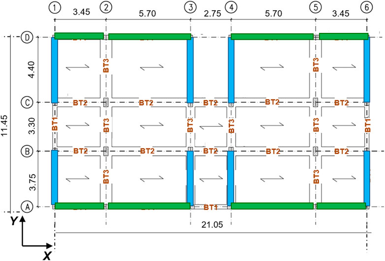
FIGURE 7. Positions of the dissipative bracing system in plan (green and light blue rectangles).
The numbers of plates to be installed on the various storeys are fixed in proportion to the inter-storey drift profiles reported in Table 3, so as to provide a response capacity proportional to the demand highlighted by the seismic assessment analysis in current conditions. Thus, they result as follows, both in X and Y: 12 plates on the ground storey, 14 on the first, 14 on the second, 10 on the third and 8 on the fourth, for a total of 58 plates per vertical alignment (by multiplying this number by the 8 alignments per axis, the npd,X = npd,Y = 464 total numbers of plates are obtained). No plates are installed on the upper storey, because of the elastic response of its structural members and the small drift values up to the MCE. However, traditional non-dissipative braces are mounted on this storey, so as to prevent discontinuities in the lateral stiffness of the structure along the height of the building. A 4.6 mm-thick circular tubular section with 150 mm diameter is adopted for the steel braces at all storeys.
Front views along the A and 1 horizontal fixed lines of the structure equipped with the protective system, and installation details of the latter in a frame span are shown in Figure 8, and a view of the finite element model including the dissipative braces in Figure 9.
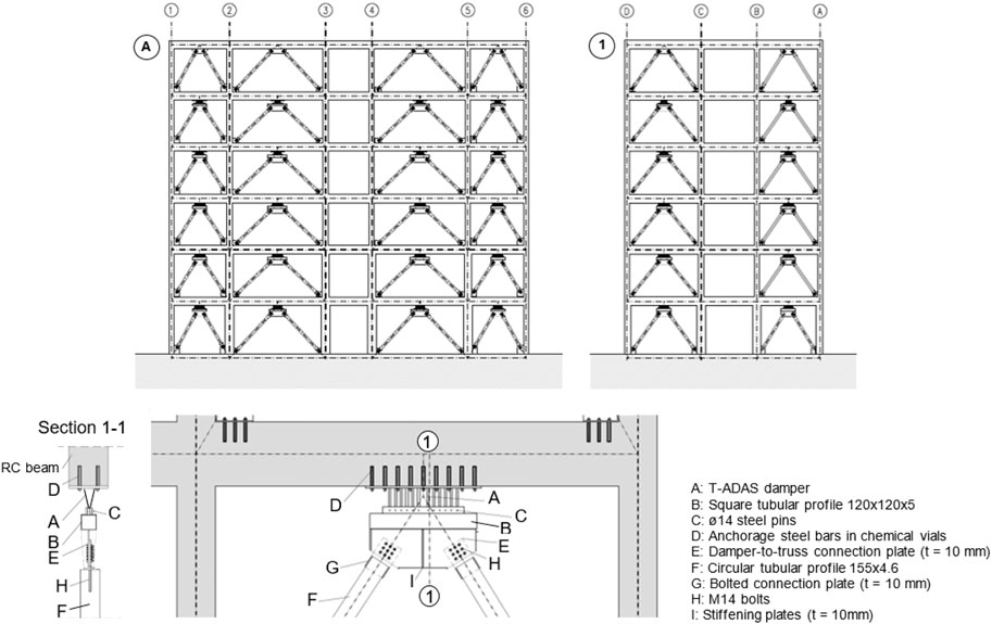
FIGURE 8. Front views of the retrofitted structure along A and 1 horizontal fixed lines, and installation details of the dissipative bracing system in a span of the frame structure.
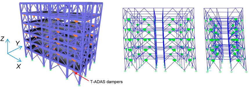
FIGURE 9. Views of the finite element model of the structure incorporating the dissipative bracing system and the first mode shapes in X and Y.
The modal analysis in retrofitted conditions highlights two main translational modes in this case too, whose shapes are shown in Figure 9, with vibration periods reduced to 0.609 s in X and 0.614 s in Y, and effective modal masses of 83.2% and 81.9%, and a first rotational mode around Z, with period and mass equal to 0.53 s and 80.7%. Like in current state, nine modes are needed to activate summed modal masses greater than 90% of the total seismic mass along X and Y, and around Z, whereas twenty-one modes—instead of eighteen—are needed to reach 99% of M. The two main translational periods are slightly greater than the TFIN,X = 0.584 s and TFIN,Y = 0.591 s values computed in the pre-sizing stage, with differences of 4.3% (X) and 3.9% (Y).
The Wen (1976) plasticity model, included in the library of SAP2000NL software, was assigned to the non-linear link elements adopted to simulate the response of the T-ADAS dampers in the time-history analyses. The results of the latter are recapitulated in the bottom halves of Tables 2, 3. Concerning storey shears (Table 2), reductions ranging from about 5% to 15% (SDE), 16%–23% (BDE) and 21%–31% (MCE) are noted when passing from original to retrofitted conditions. The growth of benefits in the transition from the lowest to the highest earthquake level is a consequence of the corresponding growth in the energy dissipated by the dampers. These data highlight that the latter compensates for—and even appreciably overcomes—the increase of shears caused by the stiffening effects of the protective system, as targeted by the sizing criterion.
The reductions in the stress states of columns and beams are significantly greater than the reductions in terms of storey shears. Indeed, as observed in Section 2, a significant portion of the latter is absorbed by the diagonal braces. The additional axial forces generated in the columns belonging to the alignments in plan where the system is installed, as well as the corresponding vertical forces transferred by the ground storey columns to the foundations, are all safely absorbed. As a consequence of the induced braced frame response mechanism to lateral forces and the supplementary damping action of the protective system, only 6% of columns and 6% of beams at the BDE, and 10% of columns and 9% of beams at the MCE are in unsafe conditions after retrofit, all situated on the ground storey. By way of example, the BDE-related M1–M2 biaxial moment curves for the columns situated on the 2/B vertical fixed line, shown in Figure 6 in current state, are duplicated in Figure 10 for retrofitted conditions. All response curves are limited within relevant safe domains, except for the ground storey column, where the demand/capacity ratio reaches a maximum value of 1.25. Similar results are obtained for the remaining ground storey columns in unsafe conditions (located on the 2/C, 3/A, 3/B, 3/C, 4/A, 4/B, 4/C, 5/B, 5/C lines, in addition to 2/B). The beams in unsafe conditions are the ones connecting these columns, with maximum demand/capacity ratios equal to 1.18 for bending moment, and 1.23 for shear. Thus, minimal local strengthening interventions are needed on these ground storey members, which consist in bonding single sheets of carbon fiber reinforced fabrics.
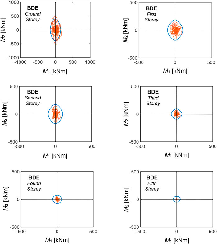
FIGURE 10. M1–M2 biaxial moment interaction curves (red lines) for the columns belonging to the 3/B vertical fixed line obtained from the most demanding BDE-scaled group of input accelerograms in retrofitted conditions, and relevant safe domains (blue lines).
The results in terms of drifts (Table 3) highlight that the target value of 0.5% IH is met on all storeys at the BDE, except for the first one, where it is marginally exceeded (0.51% in X, and 0.52% in Y). A satisfactory response is obtained up to the MCE, with peak drifts of 0.64% (X) and 0.66% (Y) on the same storey, and values below or equal to 0.5% IH on the ground, fourth and fifth storey.
The BDE-related response cycles of the dampers installed in the 2/D-3/D (parallel to X) and 1/C-1/D (parallel to Y) alignments are plotted in Figures 11, 12. By computing the energies dissipated by the dampers in their widest response cycles and the energies dissipated in all remaining cycles, the latter result to be equal to about 10.6 (2/D-3/D alignment dampers) and 11.2 (1/C-1/D alignment dampers) times the former. Similar values are calculated for all the remaining system alignments due to the substantial regularity of the building in plan and elevation, which determines slight seismic torsion effects. These data are well related to the value 10 assumed in the design expression (13), which underestimates the average values computed for the dampers situated in all alignments by about 10%. Concerning this estimate, it should be noted that the energy contribution associated with the secondary cycles is a function of the type of input ground motions assumed in the analysis. Indeed, a value approximately equal to 10 is well suited for artificial accelerograms generated from normative response spectra, like the ones used in this study, characterized by a considerable number of acceleration peaks with comparable amplitude to the widest peak. In the case of real ground motion records, the secondary peaks tend to be smaller. Therefore, the ratio of the energy dissipated in the secondary cycles to the one dissipated in the widest response cycle approximately ranges from 4 to 7, depending on several seismological, subsoil and building site factors (Sorace et al., 2016). This must be properly taken into account upon applying Eq. 13 when real ground motions, instead of artificial accelerograms, are used as input in the assessment analysis.
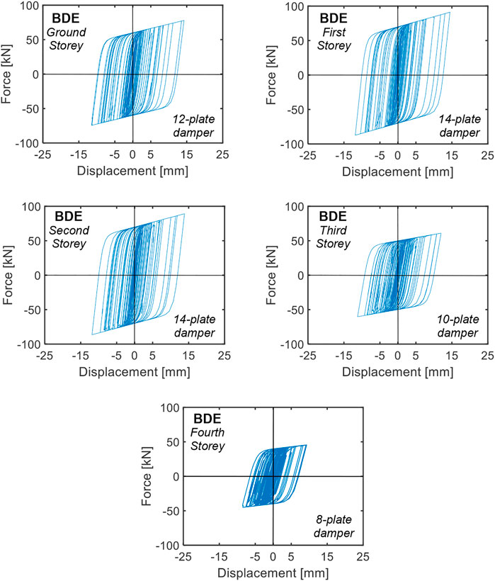
FIGURE 11. Response cycles of the dampers installed in the 2/D-3/D alignment obtained from the most demanding BDE-scaled group of input accelerograms.
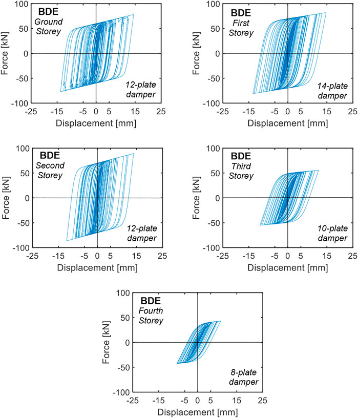
FIGURE 12. Response cycles of the dampers installed in the 1/C-1/D alignment obtained from the most demanding BDE-scaled group of input accelerograms.
By computing the total energy dissipated by the 464 + 464T-ADAS dampers, a value of 2489 kJ results at the BDE, i.e., 19.8% smaller than the sum of the Ed,X = 1632 kJ and Ed,Y = 1481 kJ values estimated by means of relation (11) in the sizing process, equal to 3103 kJ. This difference is motivated by the fact that the maximum displacements achieved in the response cycles of the dampers are nearly equal to 15 mm on the ground, first and second storey, 13 mm on the third and 8.5 mm on the fourth, that is, about 12%, 24%, and 50% smaller than the tentatively assumed dmax,e = IDm,t value, respectively. The resulting average 22% overestimation of peak displacements in the storeys is only partially compensated by about 10% underestimation of the dissipated energy contribution supplied by the secondary cycles, resulting in the above-mentioned approximate 20% overestimation yielded by the Ed,X, Ed,Y values.
The use of supplementary damping devices with high elastic stiffness requires, unlike pure dampers or low-stiffness dampers, proper control of the stiffening effects produced by their installation in dissipative bracing systems adopted as retrofit measure for existing frame structures. This is the case of ADAS dampers, the elastic stiffness of which is normally so high that the system behaves like a corresponding traditional bracing system up to the first plasticization of the devices.
A sizing procedure for ADAS dampers aimed at expressly controlling the stiffening effects involved in their application is offered in this study, whose conceptual and practical implications are summarized below.
- The procedure allows estimating the energy dissipation capacity to be assigned to the protective system by means of simple analytical relations making use of spectral displacement, velocity and pseudo-acceleration ordinates.
- As the energy dissipation preliminary estimate is obtained by means of a single linear analytical relation, the procedure is intrinsically not iterative. This marks a distinction as compared to sizing criteria based on non-linear expressions or trial-and-error tentative approaches.
- The damping action of the ADAS devices is calibrated in order to generate a prefixed pseudo-acceleration drop, ΔSA-,diss, compensating for the corresponding rise, ΔSA+, induced by the stiffening effects of the intervention.
- This compensation is modulated by means of the med energy dissipation demand coefficient to be calibrated on the design objectives formulated in terms of base shear, for which a value smaller than 1 can be selected in the case of essentially regular structures, so as to avoid excessive supplementary damping additions.
- This assumption, as well as the ones concerning the remaining parameters required to initialize the sizing process (the dmax,e maximum displacement of the damper plates, and the Ed,p,c total energy dissipated by the plates in the cycles with smaller amplitude than the widest cycle) are substantially validated for the examined frame building by the results of the non-linear time-history analyses carried out in the final verification stage.
- The latter results also satisfactorily meet the preliminarily estimated base shear and inter-storey drift demands.
- At the same time, energy demand is overestimated by about 20%, since while the estimated maximum damper displacements are nearly reached on the three lower storeys, where the peak response displacements are at most 12% smaller than the tentatively assumed dmax,e = IDm,t value, the differences reach about 24% and 50% on the third and fourth storey.
- Although this may suggest the need to further reduce the number of plates on these two storeys, as compared to the lower storeys, the exploitation of the energy dissipation capacities of the dampers is similar at all levels. This confirms the drift-proportional variation of the number of plates along the height of the structure as an acceptable choice at the sizing stage.
- Based on these results, in order to approximate better the maximum damper displacement demand for taller frame buildings than the case study one, it can be suggested to assume dmax,e = IDm,t for the storeys belonging to their bottom half, and a progressively decreasing value along the height (e.g., ranging from about 0.8 to 0.5 IDm,t) for the remaining storeys where the system is installed.
- Thanks to the balanced contributions of the stiffening and damping effects added by the dissipative braces, a satisfactory seismic performance improvement of the case study building is achieved in retrofitted conditions; this is assessed by the peak drifts practically constrained below the Immediate Occupancy-related 0.5% IH limitation at the BDE (and no greater than 0.66% peak values at the MCE), and the small number of frame members in slightly unsafe state (6% of columns and 6% of beams at the BDE, and 10% of columns and 9% of beams at the MCE). For these members, minimal local strengthening interventions based on the application of carbon fiber reinforced fabrics are suggested, as an alternative to a more expensive increase in the number of plates of the T-ADAS devices.
The raw data supporting the conclusions of this article will be made available by the authors, without undue reservation.
GT and SS equally contributed to the conception of the study and formulation of the sizing design procedure; GT, SS, and EF equally contributed to the development of numerical analyses, elaboration, and interpretation of results, and preparation of the draft manuscript.
This work was financed by DPC—Italian Department of Civil Protection, within the DPC-ReLUIS (Italian network of University laboratories of earthquake engineering) 2022-2024 Project—WP15: Normative contributions for Isolation and Dissipation.
The authors declare that the research was conducted in the absence of any commercial or financial relationships that could be construed as a potential conflict of interest.
All claims expressed in this article are solely those of the authors and do not necessarily represent those of their affiliated organizations, or those of the publisher, the editors and the reviewers. Any product that may be evaluated in this article, or claim that may be made by its manufacturer, is not guaranteed or endorsed by the publisher.
Aiken, I. D., Nims, D. K., Whittaker, A. S., and Kelly, J. M. (1993). Testing of passive energy dissipation systems. Earthq. Spectra 9 (3), 335–370. doi:10.1193/1.1585720
Akehashi, H., and Takewaki, I. (2021). Ideal drift response curve for robust optimal damper design for elastic-plastic MDOF structures under multi-level earthquakes. Comput. Model. Eng. Sci. 129 (3), 1181–1207. doi:10.32604/cmes.2021.017204
Aloisio, A., Rosso, M. M., Iqbal, A., and Fragiacomo, M. (2022). Hysteresis modeling of timber-based structural systems using a combined data and model-driven approach. Comput. Struct. 269 (3), 106830. doi:10.1016/j.compstruc.2022.106830
ASCE (2017). ASCE/SEI 41-17 – seismic evaluation and retrofit of existing buildings. Reston, VA: ASCE-American Society of Civil Engineers – Structural Engineering Institute.
ASCE (2000). Fema 356 – prestandard and Commentary for the seismic rehabilitation of buildings. Reston, VA: ASCE-American Society of Civil Engineers.
ATC (2003). ATC 58-2. Preliminary evaluation of methods for defining performance. Redwood City, CA: ATC-Applied Technology Council.
Bergman, D. M., and Goel, S. C. (1987). Evaluation of cyclic testing of steel-plate devices for added damping and stiffness. Report UMCE 87-10. Ann Arbor, MI: Department of Civil Engineering, University of Michigan.
Boggian, F., Tardo, C., Aloisio, A., Marino, E. M., and Tomasi, R. (2022). Experimental cyclic response of a novel friction connection for seismic retrofitting of RC buildings with CLT panels. ASCE J. Struct. Eng. 148 (5), 04022040. doi:10.1061/(ASCE)ST.1943-541X.0003313
CSI (2022). SAP2000NL. Theoretical and user’s manual. Release 23.07. Berkeley, CA: Computers & Structures Inc.
Dargush, G. F., and Soong, T. T. (1995). Behavior of metallic plate dampers in seismic passive energy dissipation systems. Earthq. Spectra 11 (4), 545–568. doi:10.1193/1.1585827
De Domenico, D., and Hajirasouliha, I. (2021). Multi-level performance-based design optimisation of steel frames with nonlinear viscous dampers. Bull. Earthq. Eng. 19, 5015–5049. doi:10.1007/s10518-021-01152-7
Di Trapani, F., Malavisi, M., Marano, G. C., Sberna, A. P., and Greco, R. (2020). Optimal seismic retrofitting of reinforced concrete buildings by steel-jacketing using a genetic algorithm-based framework. Eng. Struct. 219, 110864. doi:10.1016/j.engstruct.2020.110864
Fardis, M. N. (2007). Guidelines for displacement-based design of buildings and bridges. LESSLOSS Report No. 2007/05. Pavia, Italy: IUSS Press, 231. ISBN: 978-88-6198-009-9.
Gandelli, E., De Domenico, D., and Quaglini, V. (2021). Cyclic engagement of hysteretic steel dampers in braced buildings: A parametric investigation. Bull. Earthq. Eng. 19, 5219–5251. doi:10.1007/s10518-021-01156-3
Greco, R., and Marano, G. C. (2016). Optimum design of viscous dissipative links in wall-frame systems. Struct. Des. Tall Special Build. 25 (9), 412–428. doi:10.1002/tal.1265
Italian Ministry of Infrastructure and Transport (2018). Update of technical Standards for constructions. Rome, Italy: D.M. 17-01-2018(in Italian).
Khoshkalam, M., Mortezagholi, M. H., and Zahrai, S. M. (2022). Proposed modification for ADAS damper to eliminate axial force and improve seismic performance. J. Earthq. Eng. 26 (10), 5130–5152. doi:10.1080/13632469.2020.1859419
Kookalani, S., Shen, D., Zhu, L. L., and Lindsey, M. (2022). An overview of optimal damper placement methods in structures. Iran J. Sci. Technol. Trans. Civ. Eng. 46, 1785–1804. doi:10.1007/s40996-021-00752-2
Lavan, O., and Dargush, G. F. (2009). Multi-objective evolutionary seismic design with passive energy dissipation systems. J. Earthq. Eng. 13, 758–790. doi:10.1080/13632460802598545
Lu, W. T., and Phillips, B. M. (2022). A fundamental-period-preserving seismic retrofit methodology for low-rise buildings with supplemental inerters. Eng. Struct. 266, 114583. doi:10.1016/j.engstruct.2022.114583
Marano, G. C., Trentadue, F., and Greco, R. (2007). Stochastic optimum design criterion of added viscous dampers for buildings seismic protection. Struct. Eng. Mech. 25 (1), 21–37. doi:10.12989/sem.2007.25.1.021
Martinez-Romero, E. (1993). Experiences on the use of supplementary energy dissipators on building structures. Earthq. Spectra 9 (3), 581–625. doi:10.1193/1.1585731
Mazza, F. (2014). Displacement-based seismic design of hysteretic damped braces for retrofitting in-plan irregular r.c. framed structures. Soil Dyn. Earthq. Eng. 66, 231–240. doi:10.1016/j.soildyn.2014.07.001
Mazza, F., and Imbrogno, G. (2019). Effects of fire duration on the seismic retrofitting with hysteretic damped braces of r.c. school buildings. Front. Built Environ. 5, 141. doi:10.3389/fbuil.2019.00141
Moghaddasi, M., and Namazi, A. (2016). Assessment of performance of TADAS dampers for the seismic rehabilitation of buildings. Int. J. Appl. Eng. Res. 11 (21), 10516–10523. doi:10.37622/010516
Mohammadi, R. K., Nasri, A., and Ghaffary, A. (2017). TADAS dampers in very large deformations. Int. J. Steel Struct. 17, 515–524. doi:10.1007/s13296-017-6011-y
Priestley, M. J. N., and Calvi, G. M. (1997). “Concepts and procedures for direct displacement-based design and assessment,” in Seismic design methodologies for the next generation of codes (UK: Routledge), 11. ISBN: 9780203740019. doi:10.1201/9780203740019-16
Priestley, M. J. N., Calvi, G. M., and Kowalsky, M. J. (2007). Displacement-based seismic design of structures. Pavia, Italy: IUSS Press, 721. ISBN: 978-88-6198-0006.
Priestley, M. J. N. (1997). Displacement-based seismic assessment of existing reinforced concrete buildings. J. Earthq. Eng. 1, 157–192. doi:10.1080/13632469708962365
SEAOC (1995). “Performance-based seismic engineering.” in. Vision 2000 committee. Sacramento, CA: Structural Engineers Association of California.
Shojaeifar, H., Maleki, A., and Lotfollahi-Yaghin, M. A. (2020). Performance evaluation of curved-TADAS damper on seismic response of moment resisting steel frame. Int. J. Eng. 33 (1), 55–67. doi:10.5829/ije.2020.33.01a.07
Sorace, S., Terenzi, G., and Mori, C. (2016). Passive energy dissipation-based retrofit strategies for R/C frame water towers. Eng. Struct. 106, 385–398. doi:10.1016/j.engstruct.2015.10.038
Terenzi, G., Costoli, I., and Sorace, S. (2020). Activation control extension of a design method of fluid viscous dissipative bracing systems. Bull. Earthq. Eng. 18 (8), 4017–4038. doi:10.1007/s10518-020-00849-5
Teruna, D. R., Majid, T. A., and Budiono, B. (2015). Experimental study of hysteretic steel damper for energy dissipation capacity. Appl. Sci. 2015, 1–12. doi:10.1155/2015/631726
Tsai, K. C., Chen, H. W., Hong, C. P., and Su, Y. F. (1993). Design of steel triangular plate energy absorbers for seismic-resistant construction. Earthq. Spectra 9 (3), 505–528. doi:10.1193/1.1585727
Wen, Y. K. (1976). Method for random vibration of hysteretic systems. ASCE J. Eng. Mech. Div. 102 (1022), 249–263. doi:10.1061/JMCEA3.0002106
Whittaker, A. S., Bertero, V. V., Thompson, C. L., and Alonso, L. J. (1991). Seismic testing of steel plate energy dissipation devices. Earthq. Spectra 7 (4), 563–604. doi:10.1193/1.1585644
Keywords: added stiffness, added damping, dampers, design, sizing, seismic retrofit, frame structures
Citation: Terenzi G, Sorace S and Fuso E (2023) Stiffening effects-controlling sizing procedure of ADAS dampers in seismic retrofit of frame structures. Front. Built Environ. 9:1114349. doi: 10.3389/fbuil.2023.1114349
Received: 02 December 2022; Accepted: 12 January 2023;
Published: 26 January 2023.
Edited by:
Dora Foti, Politecnico di Bari, ItalyReviewed by:
Dario De Domenico, University of Messina, ItalyCopyright © 2023 Terenzi, Sorace and Fuso. This is an open-access article distributed under the terms of the Creative Commons Attribution License (CC BY). The use, distribution or reproduction in other forums is permitted, provided the original author(s) and the copyright owner(s) are credited and that the original publication in this journal is cited, in accordance with accepted academic practice. No use, distribution or reproduction is permitted which does not comply with these terms.
*Correspondence: Stefano Sorace, c3RlZmFuby5zb3JhY2VAdW5pdWQuaXQ=
Disclaimer: All claims expressed in this article are solely those of the authors and do not necessarily represent those of their affiliated organizations, or those of the publisher, the editors and the reviewers. Any product that may be evaluated in this article or claim that may be made by its manufacturer is not guaranteed or endorsed by the publisher.
Research integrity at Frontiers
Learn more about the work of our research integrity team to safeguard the quality of each article we publish.