 Yun-Peng Zhu
 Z. Q. Lang
 Kohei Fujita
 Izuru Takewaki
94% of researchers rate our articles as excellent or good
Learn more about the work of our research integrity team to safeguard the quality of each article we publish.
Find out more
ORIGINAL RESEARCH article
Front. Built Environ., 23 September 2022
Sec. Earthquake Engineering
Volume 8 - 2022 | https://doi.org/10.3389/fbuil.2022.971260
Additional power law nonlinear damping has shown advantages in seismic isolation of buildings. The design of nonlinear damped building isolation systems can be conducted in the frequency domain based on the output frequency response function (OFRF) of the building’s frequency output responses. But this often requires many runs of simulations of nonlinear building systems, which will spend a long time when the finite element (FE) model or differential equation model of the building system is complex. In this study, the issue will be resolved by an integrated mobility analysis and equivalent linearization approach. In this approach, the complex linear building system without additional nonlinear damping is represented by several data-driven autoregressive with exogenous input (ARX) models. Mobilities of the building system can be evaluated from these ARX models, so that a mobility-based frequency domain representation of the linear building system can be achieved. After that, an equivalent linearization approach is applied to simulate the building system with additional nonlinear damping. Finally, the OFRF-based design can be conducted based on the proposed mobility analysis and equivalent linearization approach. A 4-degree of freedom (DoF) building system is discussed to demonstrate the advantages of the proposed method. The results indicate that the new approach can significantly increase the efficiency of the design and be effectively applied to the design of complex nonlinear building isolation systems.
Power law nonlinear damping has been proven to have many advantages in the vibration control of building structures under earthquake ground motions, that additional power law nonlinear damping can reduce forces and displacements transmitted to buildings over a wide-band frequency range (Lang et al., 2009; Peng et al., 2011). The design of nonlinear damping has been comprehensively studied to achieve a desired building vibration isolation performance (Lang et al., 2013; Menga et al., 2021). For example, Lang et al. (2013) studied the optimal displacement and values of additional nonlinear damping isolators in a multistorey building subject to both harmonic and earthquake loadings. In general, the design of a nonlinear building isolation system finds optimal nonlinear damping values based on many runs of simulations. The design approach includes the trial-and-error approach and response surface methods (RSMs) (Khuri and Mukhopadhyay, 2010). But this is often ineffective and time-consuming when the finite element (FE) model or differential equations of the building system is complex (Fujita et al., 2014).
For linear systems, complex FE models or differential equations of building systems can be simplified by using mobility analysis (Mak and Jianxin, 2003). Mobility is defined in the frequency domain as the spectrum ratio of velocity and force (Gardonio and Brennan, 2002). Early in 1968, Soliman and Hallam (1968) proposed the mobility power flow approach enabling the analysis of vibration isolations between non-rigid machines and non-rigid foundations. It has shown that, if the mobilities of both non-rigid machines and non-rigid foundations were achieved, the system responses can be calculated in the frequency domain by using these mobilities. Since then, passive solutions using spring and damper to complex linear vibration isolation problems were developed based on the mobility power flow approach for transportation, marine, manufacturing, and construction applications (Koh, 1992; Mak and Su, 2002; Elliott et al., 2004). For example, Mak and Su (2002) applied the mobility analysis to address the occasional occurrence of unsatisfactory performance of vibration isolators observed in isolating vibratory machines placed on a concrete floor. Elliott et al. (2004) discussed the mobility analysis of active vibration isolation systems. Output responses of vibration isolation systems were derived in terms of the mobilities of the two structures connected by an active mount. Then frequency control techniques can be applied to stabilize the vibration isolation system. In practice, most systems are often too complex to theoretically achieve mobilities. In these cases, system mobilities can be directly evaluated from experiments by using modal testing approaches (Cremer and Heckl, 2013). However, this often requires many separate tests on the components of the system (Koh, 1992) to evaluate the mobilities of interest. In this study, system identification is applied to enable the evaluation of building system mobilities using a single experimental test or FE simulation. Autoregressive with exogenous input (ARX) models (Billings, 2013) of the inspected output velocity with respect to the related forces are identified under sufficiently random excitations. Then, the mobilities can be directly evaluated from these ARX models.
Although mobility analysis has been applied to the analysis of many complex vibration isolation systems, it is difficult to extend the idea to study nonlinear damped building isolation systems. The reason behind these difficulties is that the traditional mobility analysis and design is basically a linear approach, which cannot be directly applied to the nonlinear case. The current issue in the design of the building isolation system is the lack of the efficient approach that can be used to simulate nonlinear damped building isolation systems. Recently, Elloit et al. (2015) proved that the output responses of a nonlinear system can be calculated by using an equivalent linear system. In order to resolve the existing issue mentioned earlier, an integrated mobility analysis and equivalent linearization approach will be developed to simulate the building isolation system with additional nonlinear damping.
In practice, the output frequency response functions (OFRFs) have been successfully applied to the frequency design of engineering nonlinear materials and structures (Lang et al., 2007; Zhu and Lang, 2017). The OFRF indicates that nonlinear output spectra subject to demanding loads can be represented by polynomial functions of system design parameters, so that convex optimization and design of system nonlinear dynamics can be conducted (Xiao and Jing, 2015; Zhu and Lang, 2017). In this study, the OFRF representation of the nonlinear damped building isolation system is evaluated based on the numbers of simulations conducted by using the integrated mobility analysis and equivalent linearization approach. After that, an optimization problem is formulated according to the design requirements, and the OFRF representations are implemented to solve the optimal design problem.
The design of a 4- degree of freedom (DoF) nonlinear damped building isolation system will be discussed to demonstrate the application of the proposed analysis and design approach. The results indicate that the design efficiency increases over 50% compared to the traditional design based on solving nonlinear differential equations. The research outcomes are expected to be applied to address seismic isolation problems in various complex building systems.
Consider a building that can be simplified into a 4-DoF system as illustrated in Figure 1a, where
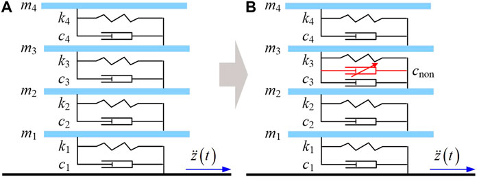
FIGURE 1. 4-DoF building system. (A) The linear 4-DoF building, (B) The 4-DoF building with nonlinear damping isolator.
The linear 4-DoF building system in Figure 1a can be expressed as
where
The output vector:
With
The aim of the design was to apply an additional nonlinear damping
In general, the frequency output responses of the nonlinear damped building isolation system can be represented by the OFRF as polynomial functions of the additional nonlinear damping for the system design (Lang et al., 2007). In traditional nonlinear damping design, many runs of simulations of the nonlinear damped building isolation system under different nonlinear damping values are needed to evaluate the OFRF representation. Then the OFRF representation can be applied to implement the system design (Fujita et al., 2014). The design process is illustrated in Figure 2. However, simulations based on solving nonlinear differential equations or applying FE simulations will become inefficient and time-consuming when the building structure is complex.
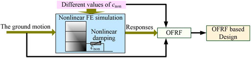
FIGURE 2. Traditional design of nonlinear damped building isolation system.
In order to address this problem, a novel integrated mobility analysis and equivalent linearization of nonlinear damped building isolation system will be developed next. In this approach, only one linear simulation is required to identify a frequency domain representation of building dynamics, known as the linear mobility model, based on which the simulations of the nonlinear damped building isolation system can be conducted much faster than solving the differential equations or applying FE simulations. The new design approach is illustrated in Figure 3 below.
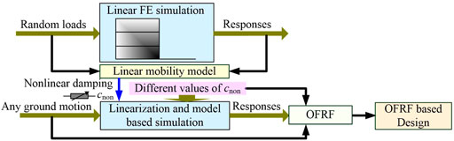
FIGURE 3. New mobility based design of nonlinear damped building isolation system.
In the following studies, the approach will be developed and demonstrated by using the 4-DoF building isolation system illustrated in Figure 1.
The 4-DoF linear building system in Figure 1a can be represented as a 3-layer multiple-input multiple-output (MIMO) vibration isolation system shown in Figure 4a, where
are input forces induced by the ground motion;
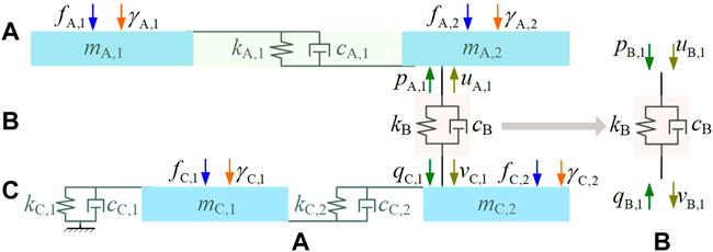
FIGURE 4. Three layer MIMO model of the 4-DoF building isolation system. (A) The three layer MIMO model, (B) The forces and velocities of thee isolator in layer B.
According to the mobility analysis approach (Soliman and Hallam, 1968), the velocity-force relationship of layer A can be represented as
where
where
The four pole relationship of layer B (Molloy, 1957) can be written as
where
For layer C, there is
where
where
According to Eqs 7, 10, there are
and
It is noticed that
Substituting
and
respectively.
By adding (14) and (15), the output force
where
When
Therefore, the linear 4-DoF system can be simulated in the frequency domain when the mobilities
Since
and
Eqs 17, 18 indicate that the velocities
where
The mobilities of layers A and C can be directly achieved from the ARX model, such as
where
In order to identify the ARX models, random excitations
For example, letting
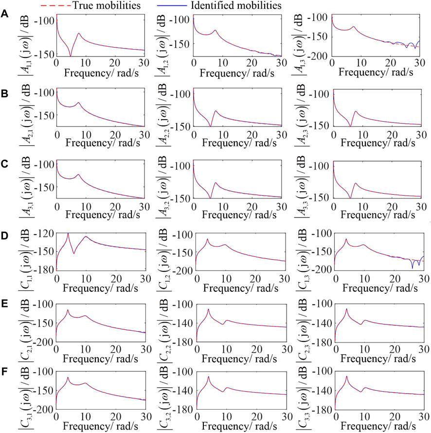
FIGURE 5. Mobilities of the 4-DoF building system. (A-C): The mobilities of layer A, (D-F): The mobilities of layer B.
Subject to a Kokuji wave ground motion shown in Figure 6, the output force spectra
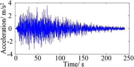
FIGURE 6. Input ground motion.
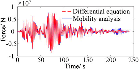
FIGURE 7. Output force of the 4-DoF system.
Consider the 4-DoF building system with additional nonlinear damping in Figure 1b. Denote
The 3-layer representation of the nonlinearly damped 4-DoF system is illustrated in Figure 8.
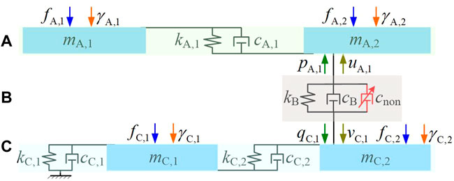
FIGURE 8. Three layer MIMO model of the 4-DoF nonlinear damped building isolation system.
The nonlinear damped system in Figure 8 can be calculated by the linear mobility approach using equivalent linearization. By finding a linear damping
Assuming the equivalent damping force is
The equivalence of the damping force is achieved by the error minimization approach (Elliott et al., 2015). The mean square error (MSE) between the nonlinear damping force and the equivalent linear damping force is
where
To minimize the MSE (24), letting
so that
It should be noted that the relative velocity
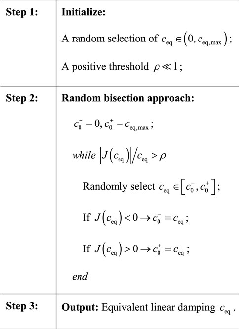
which can be iteratively solved using a bisection searching algorithm introduced in Appendix B.
Consider the additional nonlinear damping is
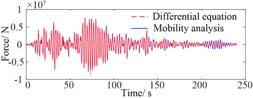
FIGURE 9. Output force of the nonlinearly damped 4-DoF system.
By solving nonlinear differential equations, it took 2.65 s to achieve the output forces, while 1.62 s were needed using the mobility model. The efficiency increases
The design requirement is to reduce the story drifts
Two optimization problems are discussed as follows.
1) Case study 1
Consider the optimization problem.
Find
Subject to the constraint
The output spectrum of the story drifts
where
Therefore, the energies
where
In order to evaluate the OFRF representations of the energies, the story drift energies are simulated by using the mobility analysis and the equivalent linearization approach under
where
The coefficients
As a result, the OFRF representations of
and shown in Figure 10.
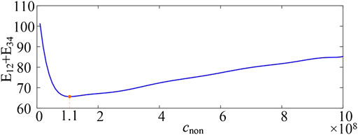
FIGURE 10. Output energy of the nonlinearly damped 4-DoF system. (A) The linear 4-DoF building, (B) The 4-DoF building with nonlinear damping isolator.
The optimized nonlinear damping can then be achieved by solving the optimization problems Eqs 28, 29 as
2) Case study 2
Denote the power loss as
where
Consider the optimization problem.
Find
Subject to the constraint
According to the discussion in case study 1, the power loss of the nonlinear damped building isolation system can be represented by OFRFs, which were evaluated as
and shown in Figure 11.
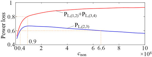
FIGURE 11. Power loss of the nonlinearly damped 4-DoF system.
The optimized nonlinear damping can then be achieved as
The design of a nonlinear damped building isolation system based on many runs of FE simulations or differential equations is often inefficient and time-consuming. For linear vibration isolation systems, mobility analysis can produce more efficient simulation processes than FE or differential equation methods. However, traditional mobility analysis requires separate tests or simulations on system components, and can only be applied to study linear systems. In order to solve these issues in the design of nonlinear damped building isolation systems, a novel data-driven–based evaluation of mobilities and equivalent linearization of nonlinear damping were developed in this study. For a linear building system, several ARX models can be identified from a single test of the building system to evaluate system mobilities. After that, the building system with additional nonlinear damping was simulated by using the equivalent linearization approach, based on which the OFRF-based design of nonlinear damping was conducted. Two case studies on the design of a 4-DoF nonlinear damped building isolation system were discussed. The results indicate the design efficiency increases by over 50% compared to traditional design methods.
In summary, the new approach is more efficient than traditional methods because the mobility model of a complex building isolation system is much simpler than a differential equation or FE model. Such a model can be achieved through a single test on the differential equation or FE model. After that, all the designs can be conducted based on the mobility model. The proposed approach can be extended to more complex building systems to further increase the design efficiency. Moreover, the results can also be applied to nonlinear vibration isolation design in manufacturing and vehicle engineering.
The original contributions presented in the study are included in the article/Supplementary Material; further inquiries can be directed to the corresponding author.
Y-PZ and ZQL developed the method applied in this manuscript; KF and IT provide the case study and necessary support from the engineering aspect to complete the manuscript.
This work was supported by the United Kingdom EPSRC grant: EP/R032793/1.
The authors declare that the research was conducted in the absence of any commercial or financial relationships that could be construed as a potential conflict of interest.
All claims expressed in this article are solely those of the authors and do not necessarily represent those of their affiliated organizations, or those of the publisher, the editors, and the reviewers. Any product that may be evaluated in this article, or claim that may be made by its manufacturer, is not guaranteed or endorsed by the publisher.
Billings, S. A. (2013). Nonlinear system identification: NARMAX methods in the time, frequency, and spatio-temporal domains. New Jersey, United States: John Wiley & Sons.
Cremer, L., and Heckl, M. (2013). Structure-borne sound: Structural vibrations and sound radiation at audio frequencies. Berlin, Germany: Springer Science & Business Media.
Elliott, S. J., Benassi, L., Brennan, M. J., Gardonio, P., and Huang, X. (2004). Mobility analysis of active isolation systems. J. Sound Vib. 271 (1-2), 297–321. doi:10.1016/s0022-460x(03)00770-3
Elliott, S. J., Tehrani, M. G., and Langley, R. S. (2015). Nonlinear damping and quasi-linear modelling. Phil. Trans. R. Soc. A 373, 20140402. doi:10.1098/rsta.2014.0402
Fujita, K., Kasagi, M., Lang, Z. Q., Guo, P. F., and Takewaki, I. (2014). Optimal placement and design of nonlinear dampers for building structures in the frequency domain. Earthquakes Struct. 7 (6), 1025–1044. doi:10.12989/eas.2014.7.6.1025
Gardonio, P., and Brennan, M. J. (2002). On the origins and development of mobility and impedance methods in structural dynamics. J. Sound Vib. 249 (3), 557–573. doi:10.1006/jsvi.2001.3879
Khuri, A. I., and Mukhopadhyay, S. (2010). Response surface methodology. WIREs. Comp. Stat. 2 (2), 128–149. doi:10.1002/wics.73
Koh, Y. K. (1992). “Prediction and control of vibrational power transmission between coupled structural systems,” (United Kingdom: University of Southampton). Doctoral dissertation.
Lang, Z. Q., Billings, S. A., Yue, R., and Li, J. (2007). Output frequency response function of nonlinear Volterra systems. Automatica 43 (5), 805–816. doi:10.1016/j.automatica.2006.11.013
Lang, Z. Q., Guo, P. F., and Takewaki, I. (2013). Output frequency response function based design of additional nonlinear viscous dampers for vibration control of multi-degree-of-freedom systems. J. Sound Vib. 332 (19), 4461–4481. doi:10.1016/j.jsv.2013.04.001
Lang, Z. Q., Jing, X. J., Billings, S. A., Tomlinson, G. R., and Peng, Z. K. (2009). Theoretical study of the effects of nonlinear viscous damping on vibration isolation of sdof systems. J. Sound Vib. 323 (1-2), 352–365. doi:10.1016/j.jsv.2009.01.001
Mak, C. M., and Jianxin, S. (2003). A study of the effect of floor mobility on structure-borne sound power transmission. Build. Environ. 38 (3), 443–455. doi:10.1016/s0360-1323(02)00185-3
Mak, C. M., and Su, J. X. (2002). A power transmissibility method for assessing the performance of vibration isolation of building services equipment. Appl. Acoust. 63 (12), 1281–1299. doi:10.1016/s0003-682x(02)00047-6
Menga, N., Bottiglione, F., and Carbone, G. (2021). Nonlinear viscoelastic isolation for seismic vibration mitigation. Mech. Syst. Signal Process. 157, 107626. doi:10.1016/j.ymssp.2021.107626
Molloy, C. T. (1957). Use of four‐Pole parameters in vibration calculations. J. Acoust. Soc. Am. 29 (7), 181–853. doi:10.1121/1.1918522
Peng, Z. K., Lang, Z. Q., Zhao, L., Billings, S. A., Tomlinson, G. R., and Guo, P. F. (2011). The force transmissibility of MDOF structures with a non-linear viscous damping device. Int. J. Non-Linear Mech. 46 (10), 1305–1314. doi:10.1016/j.ijnonlinmec.2011.06.009
Soliman, J. I., and Hallam, M. G. (1968). Vibration isolation between non-rigid machines and non-rigid foundations. J. Sound Vib. 8 (2), 329–351. doi:10.1016/0022-460x(68)90236-8
Xiao, Z., and Jing, X. (2015). Frequency-domain analysis and design of linear feedback of nonlinear systems and applications in vehicle suspensions. Ieee. ASME. Trans. Mechatron. 21 (1), 1–517. doi:10.1109/tmech.2015.2446519
Zhu, Y., and Lang, Z. Q. (2017). Design of nonlinear systems in the frequency domain: An output frequency response function-based approach. IEEE Trans. Control Syst. Technol. 26 (4), 1358–1371. doi:10.1109/tcst.2017.2716379
In layer B, the forces and velocities on the linear isolator are shown in Figure A1.
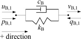
FIGURE A1. Forces and velocities of the isolator.
In Figure A1, there are
In the frequency domain, (A1) can be rewritten as
It is noticed that
Algorithm 1. The bisection searching algorithm
Keywords: nonlinear damping, building isolation, mobility, linearization, design
Citation: Zhu Y-P, Lang ZQ, Fujita K and Takewaki I (2022) The design of nonlinear damped building isolation systems by using mobility analysis. Front. Built Environ. 8:971260. doi: 10.3389/fbuil.2022.971260
Received: 16 June 2022; Accepted: 09 August 2022;
Published: 23 September 2022.
Edited by:
Massimo Latour, University of Salerno, ItalyReviewed by:
Fabio Freddi, University College London, United KingdomCopyright © 2022 Zhu, Lang, Fujita and Takewaki. This is an open-access article distributed under the terms of the Creative Commons Attribution License (CC BY). The use, distribution or reproduction in other forums is permitted, provided the original author(s) and the copyright owner(s) are credited and that the original publication in this journal is cited, in accordance with accepted academic practice. No use, distribution or reproduction is permitted which does not comply with these terms.
*Correspondence: Z. Q. Lang, ei5sYW5nQHNoZWZmaWVsZC5hYy51aw==
Disclaimer: All claims expressed in this article are solely those of the authors and do not necessarily represent those of their affiliated organizations, or those of the publisher, the editors and the reviewers. Any product that may be evaluated in this article or claim that may be made by its manufacturer is not guaranteed or endorsed by the publisher.
Research integrity at Frontiers
Learn more about the work of our research integrity team to safeguard the quality of each article we publish.