 Hiroki Akehashi
 Izuru Takewaki
95% of researchers rate our articles as excellent or good
Learn more about the work of our research integrity team to safeguard the quality of each article we publish.
Find out more
ORIGINAL RESEARCH article
Front. Built Environ. , 29 August 2022
Sec. Earthquake Engineering
Volume 8 - 2022 | https://doi.org/10.3389/fbuil.2022.964867
A set of approximate closed-form solutions of the maximum interstory drifts under the critical pseudo-double impulse (PDI) is derived for non-proportionally damped multi-story shear building models with bilinear hysteresis. The use of PDI and the closed-form solutions efficiently and accurately enable the capture of the critical responses of elastic-plastic multi-degree-of-freedom (MDOF) systems under the one-cycle sine wave, which substitutes for the main part of near-fault fling-step motions. The formulation of the closed-form maximum interstory drifts is based on the energy balance law. In the formulation, a quadratic function approximation of the damping force-interstory drift relation is introduced together with an updated mode-controlled energy-based approach (UMEA). While UMEA was proposed in the previous paper to derive the approximate maximum interstory drifts of undamped elastic-plastic MDOF systems under the critical PDI, it is extended so that it can be applied to non-proportionally damped MDOF systems. It is demonstrated that the proposed method can estimate the maximum interstory drifts of elastic-plastic non-proportionally damped MDOF systems under the critical PDI and the corresponding one-cycle sine wave with high accuracy. The estimation by the proposed method can be conducted much more efficiently and stably than the time-history response analysis (THRA). It is also shown that the hysteretic energy dissipation is not large enough to reduce the maximum interstory drifts. Finally, it is demonstrated that the proposed method can accurately estimate the maximum interstory drifts of elastic-plastic moment-resisting frames with viscous dampers under the resonant one-cycle sine wave.
Recently observed pulse-like near-fault ground motions greatly exceed the level of code-specified ground motions. Such ground motions may concentrate the plastic deformation to specific stories and cause devastating damage to building structures. However, earthquake events are uncertain and difficult to be precisely predicted. Therefore, such kind of uncertainty and the plastic deformation characteristics should be fully considered in the structural design of buildings to improve the buildings’ resilience. Many researches on the elastic-plastic response characteristics of buildings and the effectiveness of the structural control systems under near-fault ground motions have been accumulated so far (Bertero et al. (1978), Hall et al. (1995), Malhotra (1999), Jangid and Kelly (2001), Mavroeidis and Papageorgiou (2003), Bray and Rodriguez-Marek (2004), Mavroeidis et al. (2004), Akkar et al. (2005), Baker (2007), He and Agrawal (2008), Yang et al. (2010), Khaloo et al. (2015), Vafaei and Eskandari (2015), Fang et al. (2018), Hamidi et al. (2020), Akehashi and Takewaki (2020), (2022a)). However, few researchers focused on both the uncertainty of the input ground motion and the plastic deformation characteristics.
The critical excitation method is one of the most rational approaches to certainly treat the uncertainty of the input ground motion [Drenick (1970); Shinozuka (1970); Iyengar and Manohar (1987); Abbas and Manohar (2002); Au (2006); Takewaki (2013)]. The method is aimed at finding the excitation which maximizes the structural response of models under possible inputs. Generally, an iteration of numerical analyses is required to find the critical excitation for elastic-plastic models. For example, Caughey (1960a), Caughey (1960b) used the equivalent linearization technique to approximately derive the nonlinear stationary responses, and Iwan (1961), (1965a, b) formulated transcendental equations for stationary responses of elastic-plastic models under harmonic excitation. These methods require iterative procedures to find the critical (resonant) input frequency for a specified input level. Especially in the case of elastic-plastic MDOF systems, such procedures become more complicated. Moreover, these methods cannot accurately estimate the maximum responses under near-fault ground motions because the duration of such ground motions is short and the responses are not stationary.
To overcome these difficulties, Akehashi and Takewaki (2021) introduced a pseudo-double impulse (PDI) to capture the critical responses of elastic-plastic MDOF systems under fling-step ground motions. PDI is a set of impulsive lateral forces, and it substitutes for the main part of fling-step ground motions. An ordinary double impulse (DI), which was proposed by Kojima and Takewaki (2015), cannot accurately simulate the maximum responses of MDOF systems because DI is treated as a ground acceleration and largely excites the higher-mode responses. On the other hand, PDI hardly excites the higher-mode responses because the undamped fundamental participation vector is adopted as the influence coefficient vector. This reflects the critical response characteristics under the actual fling-step ground motions. It has been demonstrated that the maximum interstory drifts and the maximum floor accelerations under the critical PDI correspond well to those under the critical one-cycle sine wave, which is another substitute for the fling-step ground motions [Sasani and Bertero (2000); Makris and Black (2004); Kalkan and Kunnath (2006); Hayden et al. (2014)]. Moreover, Akehashi and Takewaki (2022b) developed an innovative displacement control analysis called an ‘updated mode-controlled energy-based approach (UMEA)’ to derive approximate closed-form critical maximum interstory drifts of elastic-plastic undamped MDOF systems. UMEA effectively captures the transitional phases of the interstory drift responses and the plastic deformation concentration under the critical PDI. However, the method by Akehashi and Takewaki (2022b) cannot treat damped elastic-plastic MDOF systems. The closed-form maximum interstory drifts of damped elastic-plastic MDOF systems under the critical PDI should be derived because the simple response evaluation will be helpful for the preliminary seismic design of structural members and passive viscous dampers.
In this paper, a set of approximate closed-form solutions of the maximum interstory drifts under the critical PDI is derived for non-proportionally damped multi-story shear building models with bilinear hysteresis. In Section 2, the relation among a one-cycle sine wave, DI and PDI is explained. In Section 3, the displacement responses of elastic MDOF systems under a single impulse are investigated when the undamped fundamental participation vector is applied to the influence coefficient vector. In Section 4, a set of approximate closed-form solutions of the maximum interstory drifts under the critical PDI is derived for a non-proportionally damped MDOF system with bilinear hysteresis. This formulation is based on an extended UMEA, a quadratic function approximation of the damping force-interstory drift relation and the energy balance law. In Section 5, the time-history response analysis (THRA) is conducted to check the accuracy of the proposed approximate closed-form expression of the maximum interstory drifts for elastic-plastic non-proportionally damped MDOF systems under the critical PDI and the corresponding one-cycle sine wave. The damping force-interstory drift relations, the hysteretic energy and the dissipated energy by viscous damping are also investigated. Finally, the applicability of the proposed approximate closed-form expression to elastic-plastic moment-resisting frames with viscous damper is investigated.
In this section, the relation among a one-cycle sine wave, a double impulse (DI) and a pseudo-double impulse (PDI) is explained briefly.
The main part of the near-fault fling-step ground motion is often expressed by the one-cycle sine wave [Sasani and Bertero (2000); Makris and Black (2004); Kalkan and Kunnath (2006); Hayden et al. (2014)]. On the other hand, Kojima and Takewaki (2015) introduced DI to more simply model the main part of the near-fault fling-step ground motion. As shown in Figure 1, the Fourier amplitude of DI and that of the one-cycle sine wave correspond well in the range of
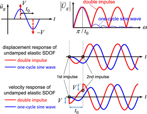
FIGURE 1. Input and response of double impulse (DI) and one-cycle sine wave.
The most important aspect of DI is that the critical maximum deformation and the critical time interval of an elastic-plastic SDOF system can be easily obtained without any repetition. This is because only the free vibration occurs after each impulse input and the energy-based approach is easily applied. Moreover, PDI has been introduced by Akehashi and Takewaki (2021), (2022b) so that this aspect can be applied to elastic-plastic MDOF systems. PDI is treated as a set of impulsive lateral forces, and the undamped fundamental participation vector is adopted as the influence coefficient vector (see Figure 2).
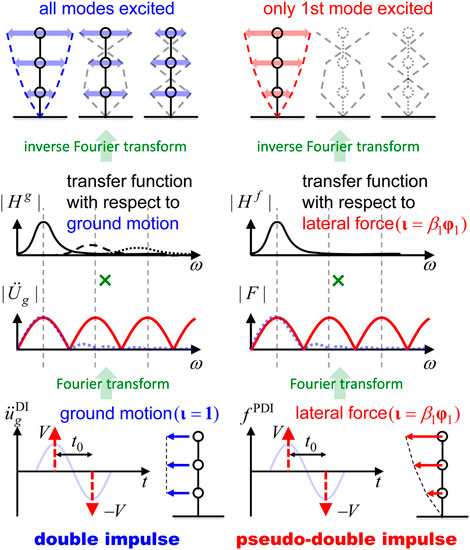
FIGURE 2. Double impulse (DI) and pseudo-double impulse (PDI).
Consider a N-story shear mass system. Let
where
PDI excites only the fundamental-mode responses of elastic proportionally-damped MDOF systems because
In this section, the displacement responses of elastic MDOF systems under a single impulse (SI) with
Consider an elastic proportionally damped MDOF system. The displacement response
where
Consider next an elastic non-proportionally damped MDOF system. The displacement response
where
It is noted that, depending on the non-proportionality of the damping distribution, the higher-mode responses are slightly excited under PSI. When the damping distribution has weak non-proportionality, the component
where
It is also noted that Equation 7 gives the exact value in the cases of elastic proportionally damped MDOF systems since
The accuracy of Equation 7 is investigated through numerical examples. Consider two 24-story shear building models with different damping distributions. Both models have a trapezoidal distribution of story stiffnesses
Figure 3 illustrates the maximum interstory drifts under PSI with
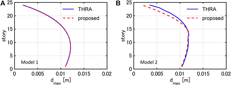
FIGURE 3. Maximum interstory drifts under PSI with
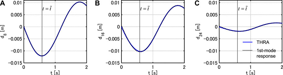
FIGURE 4. Interstory drift response time-history under PSI (Model 1), (A) 8-th story, (B) 16-th story, (C) 24-th story.
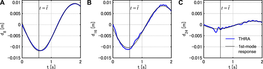
FIGURE 5. Interstory drift response time-history under PSI (Model 2), (A) 8-th story, (B) 16-th story, (C) 24-th story.
In this section, a set of approximate closed-form solutions of the maximum interstory drifts under the critical PDI is derived for non-proportionally damped MDOF systems with bilinear hysteresis. In Section 4.1, the updated mode-controlled energy-based approach (UMEA), which was introduced by Akehashi and Takewaki (2022b), is extended based on the formulation in Section 3 so that it can be applied to non-proportionally damped MDOF systems. In Section 4.2, a quadratic function approximation of the damping force-interstory drift relation is proposed. This leads to a closed-form expression of the dissipated energy by the viscous damping. In Section 4.3, the approximate closed-form solutions of the maximum interstory drifts are derived based on the extended UMEA, the quadratic function approximation and the energy balance law.
UMEA, which is a kind of displacement-controlled analyses, has been developed by Akehashi and Takewaki (2022b). UMEA leads to a set of approximate closed-form solutions of the maximum interstory drifts of elastic-plastic undamped MDOF systems under the critical PDI. UMEA provides the maximum displacement responses of the MDOF systems by considering the interstory drift increment, which is proportional to the undamped fundamental mode evaluated by the tangent story stiffnesses. It is noted that UMEA reflects the modal coupling effect due to the elastic-plastic responses under the critical PDI and the validity of UMEA was demonstrated in the previous paper [Akehashi and Takewaki (2022b)].
Although UMEA can be applied to undamped systems, it cannot be applied to damped systems. It is pointed out that viscous damping with strong non-proportionality excites the higher-mode responses, and it may influence the distribution of the maximum interstory drifts. To overcome this difficulty, UMEA is extended so that it can be applied to non-proportionally damped systems based on the formulation in Section 3. In UMEA for non-proportionally damped systems, the interstory drift increment
Consider the case where UMEA is applied to a 3DOF shear mass system with bilinear hysteresis (see Figure 6).
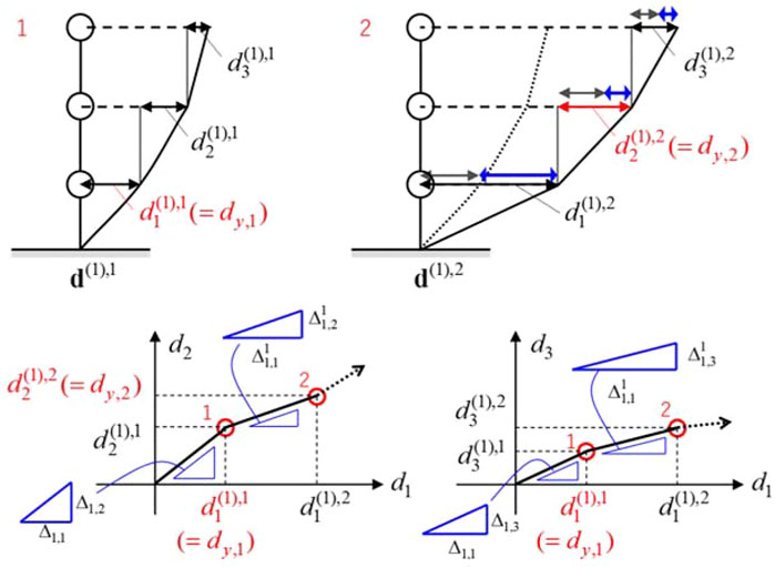
FIGURE 6. Overview of UMEA.
It is noted that, in the case of an undamped system,
Akehashi and Takewaki (2018) introduced a quadratic function approximation of the damping force-deformation relation to derive an approximate closed-form maximum deformation of an elastic-plastic SDOF system under the critical DI. This approach is extended to the damping force-interstory drift relation in each story of an elastic-plastic MDOF system.
Let
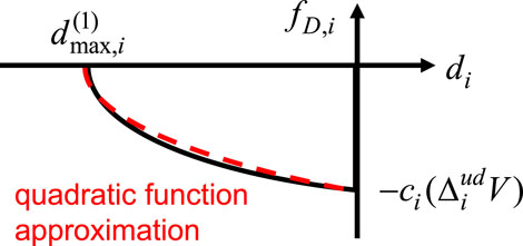
FIGURE 7. Quadratic function approximation of damping force-interstory drift relation.
By integrating Equation 9 from
This formulation helps to derive
A set of approximate closed-form solutions of the maximum interstory drifts
UMEA is conducted in the negative direction for deriving
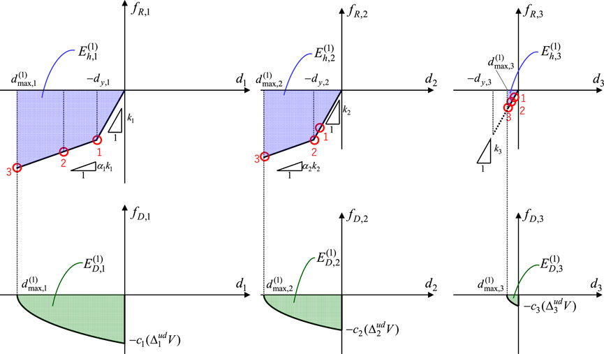
FIGURE 8. Evaluation of maximum interstory drifts
The input energy
The energy balance law between the timing just after the first impulse acts and the timing when the system attains
where
Next, the distribution
UMEA in the positive direction is conducted just after the second impulse input. Let us define
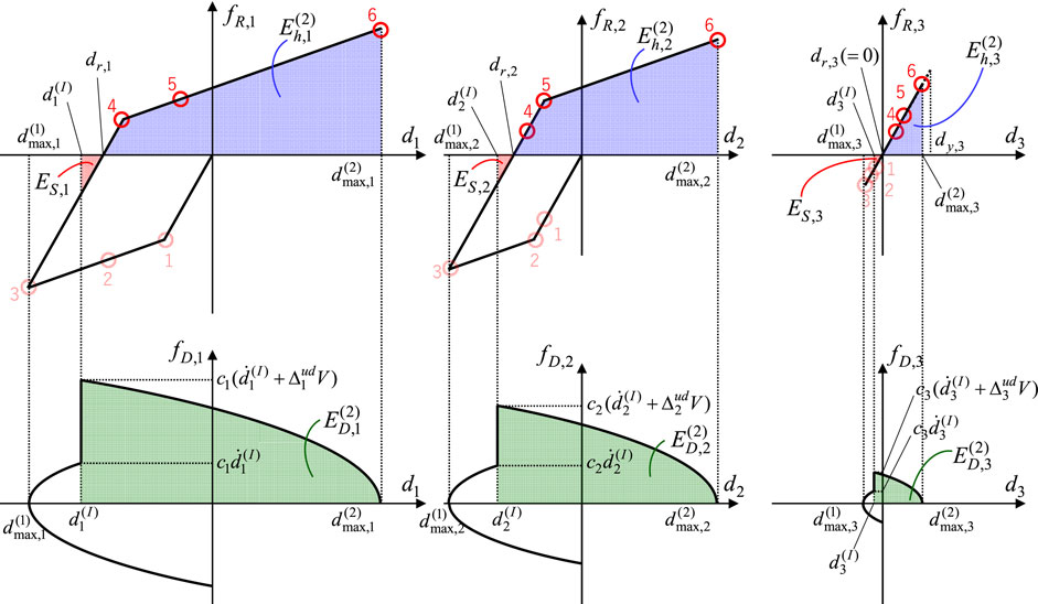
FIGURE 9. Evaluation of maximum interstory drifts
Let
The detailed formulation of
In Section 5.1, the time-history response analysis (THRA) is conducted to check the accuracy of the proposed approximate closed-form expression for elastic-plastic non-proportionally damped MDOF systems under the critical PDI. The damping force-interstory drift relations, the hysteretic energy and the dissipated energy by viscous damping are also investigated. In Section 5.2, the maximum interstory drifts under the corresponding one-cycle sine wave are compared with the proposed approximate closed-form expression. In Section 5.1, Section 5.2, Model 1
Figure 10 shows the distributions of the maximum interstory drifts by THRA under the critical PDI with
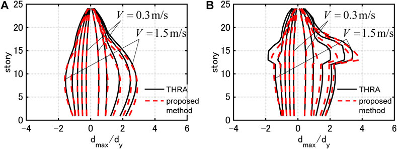
FIGURE 10. Maximum interstory drifts under critical PDI and those evaluated by proposed method,(A) Model 1
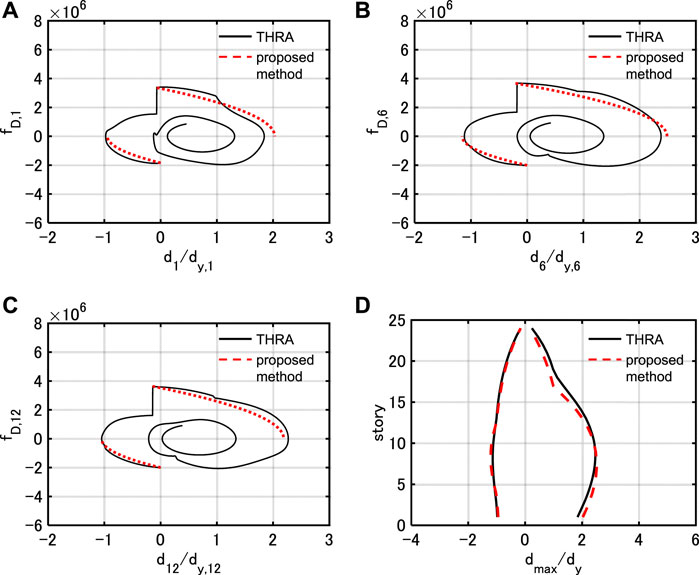
FIGURE 11. Damping force-interstory drift relation under PDI with
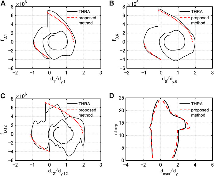
FIGURE 12. Damping force-interstory drift relation under PDI with
In the case of Model 1, the proposed method estimates the maximum interstory drifts with high accuracy for all the input levels. In addition, the approximate quadratic functions correspond well to the damping force-interstory drift relations by THRA, although the higher-mode responses slightly contribute.
In the case of Model 2, the proposed method tends to slightly overestimate the maximum interstory drifts in the 13th story. However, the proposed method estimates those in the remaining stories with high accuracy. It can be pointed out that the damping force-interstory drift relation in the 12th story by THRA does not correspond well to the corresponding quadratic function. This is because the value of the damping coefficient drastically switches at the 12, 13th stories, and the contribution of the higher-mode responses is relatively large. However, the correspondence between the estimated value of the dissipated energy (area formed by quadratic function) and the dissipated energy by THRA is fairly good.
It should be noted that the proposed method estimates the maximum interstory drifts efficiently and stably. The total computational time by the proposed method is about 1/170 of that by THRA (time step increment: 0.001s,
Figure 13 shows
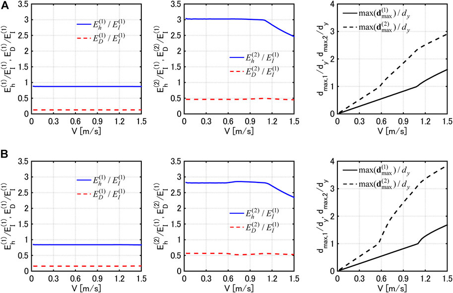
FIGURE 13. Comparison of
Figure 14 shows the distributions of the maximum interstory drifts by THRA under the corresponding one-cycle sine wave with
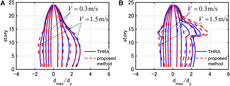
FIGURE 14. Maximum interstory drifts under corresponding one-cycle sine wave and those evaluated by proposed method, (A) Model 1, (B) Model 2.
In the case of Model 1, the maximum interstory drifts evaluated by the proposed method corresponds well to those evaluated by THRA for all the input levels. In the case of Model 2, the proposed method tends to overestimate the maximum interstory drifts in the 13–18th stories for larger input levels. This is because the non-proportionality of the damping distribution is strong and the correspondence between the critical PDI and the one-cycle sine wave gets worse. However, within the range where the plastic deformation ductility is less than 2, the maximum interstory drifts evaluated by the proposed method corresponds well to those evaluated by THRA.
In this section, the applicability of the proposed method to elastic-plastic moment resisting frames with viscous dampers is investigated. The transformation of moment frames into equivalent shear mass systems enables the application of the proposed method.
A 10-story 3-span planar moment-resisting frame is used. The details of the moment frame and the equivalent shear mass system with bilinear hysteresis are shown in the previous papers [Akehashi and Takewaki (2022b), Akehashi and Takewaki (2022c)]. The added damping coefficient
where
Figure 15 shows the distribution of the added damping coefficients by the viscous dampers and the maximum interstory drifts of the moment frame and the equivalent shear mass system under the one-cycle sine wave, which corresponds to the critical PDI with
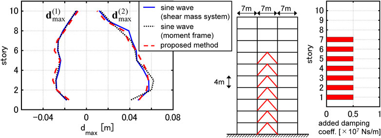
FIGURE 15. Maximum interstory drifts of moment-resisting frame and equivalent shear mass system under one-cycle sine wave and distribution of added damping coefficients.
A set of approximate closed-form solutions of the maximum interstory drifts under the critical pseudo-double impulse (PDI) was derived for non-proportionally damped multi-story shear building models with bilinear hysteresis. The main conclusions can be summarized as follows.
1) A set of approximate closed-form solutions of the maximum interstory drifts under the critical PDI was derived based on the energy balance law. While the damping was difficult to be treated in the previous paper, it was made possible to consider by extending an updated mode-controlled energy-based approach (UMEA) and introducing a quadratic function approximation of the damping force-interstory drift relation. It was demonstrated through numerical examples that the proposed method estimates the distributions of the maximum interstory drifts evaluated by the time-history response analysis (THRA) under the critical PDI. It was also demonstrated that, within the range where the plastic deformation ductility is less than 2, the maximum interstory drifts evaluated by the proposed method correspond well to those evaluated by THRA under the corresponding one-cycle sine wave.
2) The proposed method can be conducted efficiently and stably. The proposed method does not require the repetition of the matrix multiplication and the convergence calculation due to the elastic-plastic responses which are required in THRA.
3) The hysteretic energy dissipation is not large enough to reduce the maximum interstory drifts. Considering the plastic deformation concentration in specific stories, the interstory drifts may rather increase by yielding.
4) The proposed method developed for shear mass systems can estimate the maximum interstory drifts of elastic-plastic moment-resisting frames with viscous dampers under the resonant one-cycle sine wave with high accuracy.
The proposed method focuses on both the uncertainty of the input ground motion and the plastic deformation characteristics under the near-fault fling-step motions. Moreover, the proposed method can efficiently and stably estimate the critical maximum interstory drifts. Although the one-cycle sine wave substitutes well for the main part of the near-fault fling-step motions, it requires much computational load to find the critical resonant input period. By using the critical PDI, structural members and passive viscous dampers can be efficiently designed, and such design will be a resilient design because the uncertainty of the input ground motion is considered.
The raw data supporting the conclusions of this article will be made available by the authors, without undue reservation.
HA formulated the problem, conducted the computation, and wrote the paper. IT supervised the research and wrote the paper.
Part of the present work is supported by the Grant-in-Aid for Scientific Research (KAKENHI) of Japan Society for the Promotion of Science (Nos. 18H01584 and JP20J20811). This support is greatly appreciated.
The authors declare that the research was conducted in the absence of any commercial or financial relationships that could be construed as a potential conflict of interest.
All claims expressed in this article are solely those of the authors and do not necessarily represent those of their affiliated organizations, or those of the publisher, the editors and the reviewers. Any product that may be evaluated in this article, or claim that may be made by its manufacturer, is not guaranteed or endorsed by the publisher.
The Supplementary Material for this article can be found online at: https://www.frontiersin.org/articles/10.3389/fbuil.2022.964867/full#supplementary-material
Supplementary Data Sheet | Closed-form expressions on the maximum interstory drifts after the first impulse and the maximum interstory drifts after the second impulse.
Abbas, A. M., and Manohar, C. S. (2002). Investigations into critical earthquake load models within deterministic and probabilistic frameworks. Earthq. Eng. Struct. Dyn. 31 (4), 813–832. doi:10.1002/eqe.124
Akehashi, H., Kojima, K., and Takewaki, I. (2018). Critical response of single-degree-of-freedom damped bilinear hysteretic system under double impulse as substitute for near-fault ground motion. Front. Built Environ. 4, 5. doi:10.3389/fbuil.2018.00005
Akehashi, H., and Takewaki, I. (2020). Comparative investigation on optimal viscous damper placement for elastic-plastic MDOF structures: Transfer function amplitude or double impulse. Soil Dyn. Earthq. Eng. 130, 105987. doi:10.1016/j.soildyn.2019.105987
Akehashi, H., and Takewaki, I. (2021). Pseudo-double impulse for simulating critical response of elastic-plastic MDOF model under near-fault earthquake ground motion. Soil Dyn. Earthq. Eng. 150, 106887. doi:10.1016/j.soildyn.2021.106887
Akehashi, H., and Takewaki, I. (2022a). Bounding of earthquake response via critical double impulse for efficient optimal design of viscous dampers for elastic-plastic moment frames. Jpn. Archit. Rev. 5 (2), 131–149. doi:10.1002/2475-8876.12262
Akehashi, H., and Takewaki, I. (2022b). Closed-form critical response of undamped bilinear hysteretic MDOF system under pseudo-double impulse for estimating resonant response under one-cycle sine wave. Soil Dyn. Earthq. Eng. 157, 107254. doi:10.1016/j.soildyn.2022.107254
Akehashi, H., and Takewaki, I. (2022c). Inverse optimal damper placement via shear model for elastic–plastic moment-resisting frames under large-amplitude ground motions. Eng. Struct. 250, 113457. doi:10.1016/j.engstruct.2021.113457
Akkar, S., Yazgan, U., and Gülkan, P. (2005). Drift estimates in frame buildings subjected to near-fault ground motions. J. Struct. Eng. 131 (7), 1014–1024. doi:10.1061/(asce)0733-9445(2005)131:7(1014)
Au, S. K. (2006). Critical excitation of SDOF elasto-plastic systems. J. Sound. Vib. 296 (4-5), 714–733. doi:10.1016/j.jsv.2006.01.034
Baker, J. W. (2007). Quantitative classification of near-fault ground motions using wavelet analysis. Bull. Seismol. Soc. Am. 97 (5), 1486–1501. doi:10.1785/0120060255
Bertero, V. V., Mahin, S. A., and Herrera, R. A. (1978). Aseismic design implications of near-fault San Fernando earthquake records. Earthq. Eng. Struct. Dyn. 6 (1), 31–42. doi:10.1002/eqe.4290060105
Bray, J. D., and Rodriguez-Marek, A. (2004). Characterization of forward-directivity ground motions in the near-fault region. Soil Dyn. Earthq. Eng. 24 (11), 815–828. doi:10.1016/j.soildyn.2004.05.001
Caughey, T. K. (1960a). Random excitation of a system with bilinear hysteresis. J. Appl. Mech. 27 (4), 649–652. doi:10.1115/1.3644077
Caughey, T. K. (1960b). Sinusoidal excitation of a system with bilinear hysteresis. J. Appl. Mech. 27 (4), 640–643. doi:10.1115/1.3644075
Drenick, R. F. (1970). Model-free design of aseismic structures. J. Engrg. Mech. Div. 96 (4), 483–493. doi:10.1061/jmcea3.0001260
Fang, C., Zhong, Q., Wang, W., Hu, S., and Qiu, C. (2018). Peak and residual responses of steel moment-resisting and braced frames under pulse-like near-fault earthquakes. Eng. Struct. 177, 579–597. doi:10.1016/j.engstruct.2018.10.013
Hall, J. F., Heaton, T. H., Halling, M. W., and Wald, D. J. (1995). Near-source ground motion and its effects on flexible buildings. Earthq. Spectra 11, 569–605. doi:10.1193/1.1585828
Hamidi, H., Karbassi, A., and Lestuzzi, P. (2020). Seismic response of RC buildings subjected to fling-step in the near-fault region. Struct. Concr. 21 (5), 1919–1937. doi:10.1002/suco.201900028
Hayden, C. P., Bray, J. D., and Abrahamson, N. A. (2014). Selection of near-fault pulse motions. J. Geotech. Geoenviron. Eng. 140 (7), 04014030. doi:10.1061/(asce)gt.1943-5606.0001129
He, W. L., and Agrawal, A. K. (2008). Analytical model of ground motion pulses for the design and assessment of seismic protective systems. J. Struct. Eng. (N. Y. N. Y). 134 (7), 1177–1188. doi:10.1061/(asce)0733-9445(2008)134:7(1177)
Iwan, W. D. (1961). The dynamic response of bilinear hysteretic systems. Pasadena: Doctoral dissertation, California Institute of Technology.
Iwan, W. D. (1965a). The dynamic response of the one-degree-of-freedom bilinear hysteretic system. New Zealand: Proc of the Third World Conf. on Earthquake Eng.
Iwan, W. D. (1965b). The steady-state response of a two-degree-of-freedom bilinear hysteretic system. J. Appl. Mech. 32 (1), 151–156. doi:10.1115/1.3625711
Iyengar, R. N., and Manohar, C. S. (1987). Nonstationary random critical seismic excitations. J. Eng. Mech. 113 (4), 529–541. doi:10.1061/(asce)0733-9399(1987)113:4(529)
Jangid, R. S., and Kelly, J. M. (2001). Base isolation for near-fault motions. Earthq. Eng. Struct. Dyn. 30 (5), 691–707. doi:10.1002/eqe.31
Kalkan, E., and Kunnath, S. K. (2006). Effects of fling step and forward directivity on seismic response of buildings. Earthq. Spectra 22 (2), 367–390. doi:10.1193/1.2192560
Khaloo, A. R., Khosravi, H., and Jamnani, H. H. (2015). Nonlinear interstory drift contours for idealized forward directivity pulses using “modified fish-bone” models. Adv. Struct. Eng. 18 (5), 603–627. doi:10.1260/1369-4332.18.5.603
Kojima, K., and Takewaki, I. (2015). Critical earthquake response of elastic-plastic structures under near-fault ground motions (Part 1: Fling-step input). Front. Built Environ. 1, 12. doi:10.3389/fbuil.2015.00012
Makris, N., and Black, C. J. (2004). Dimensional analysis of rigid-plastic and elastoplastic structures under pulse-type excitations. J. Eng. Mech. 130 (9), 1006–1018. doi:10.1061/(asce)0733-9399(2004)130:9(1006)
Malhotra, P. K. (1999). Response of buildings to near-field pulse-like ground motions. Earthq. Eng. Struct. Dyn. 28 (11), 1309–1326. doi:10.1002/(sici)1096-9845(199911)28:11<1309::aid-eqe868>3.0.co;2-u
Mavroeidis, G. P., Dong, G., and Papageorgiou, A. S. (2004). Near-fault ground motions, and the response of elastic and inelastic single-degree-of-freedom (SDOF) systems. Earthq. Eng. Struct. Dyn. 33 (9), 1023–1049. doi:10.1002/eqe.391
Mavroeidis, G. P., and Papageorgiou, A. S. (2003). A mathematical representation of near-fault ground motions. Bull. Seismol. Soc. Am. 93 (3), 1099–1131. doi:10.1785/0120020100
Sasani, M., and Bertero, V. V. (2000). “Importance of severe pulse-type ground motions in performance-based engineering: Historical and critical,” in Proc. Of the 12th world conf. On earthq. Eng. (Upper Hutt, New Zealand: New Zealand Society for Earthq. Eng.).
Shinozuka, M. (1970). Maximum structural response to seismic excitations. J. Engrg. Mech. Div. 96 (5), 729–738. doi:10.1061/jmcea3.0001284
Takewaki, I. (2013). Critical excitation methods in earthquake engineering. Oxford: Butterworth-Heinemann.
Vafaei, D., and Eskandari, R. (2015). Seismic response of mega buckling‐restrained braces subjected to fling-step and forward-directivity near-fault ground motions. Struct. Des. Tall Spec. Build. 24 (9), 672–686. doi:10.1002/tal.1205
Keywords: critical excitation, elastic-plastic earthquake response, nonlinear resonance, pseudo-double impulse, near-fault ground motion, non-proportional damping, updated mode-controlled energy-based approach
Citation: Akehashi H and Takewaki I (2022) Closed-form critical response of elastic-plastic shear building with viscous damper under pseudo-double impulse for simulating resonant response under near-fault fling-step motion. Front. Built Environ. 8:964867. doi: 10.3389/fbuil.2022.964867
Received: 09 June 2022; Accepted: 18 July 2022;
Published: 29 August 2022.
Edited by:
Solomon Tesfamariam, University of British Columbia, CanadaReviewed by:
Binbin Li, Zhejiang University, ChinaCopyright © 2022 Akehashi and Takewaki. This is an open-access article distributed under the terms of the Creative Commons Attribution License (CC BY). The use, distribution or reproduction in other forums is permitted, provided the original author(s) and the copyright owner(s) are credited and that the original publication in this journal is cited, in accordance with accepted academic practice. No use, distribution or reproduction is permitted which does not comply with these terms.
*Correspondence: Izuru Takewaki, dGFrZXdha2lAYXJjaGkua3lvdG8tdS5hYy5qcA==
Disclaimer: All claims expressed in this article are solely those of the authors and do not necessarily represent those of their affiliated organizations, or those of the publisher, the editors and the reviewers. Any product that may be evaluated in this article or claim that may be made by its manufacturer is not guaranteed or endorsed by the publisher.
Research integrity at Frontiers
Learn more about the work of our research integrity team to safeguard the quality of each article we publish.