 Marco Donà
 Enrico Bernardi
 Alberto Zonta
 Marco Ceresara
 Francesca da Porto
95% of researchers rate our articles as excellent or good
Learn more about the work of our research integrity team to safeguard the quality of each article we publish.
Find out more
ORIGINAL RESEARCH article
Front. Built Environ. , 05 August 2022
Sec. Earthquake Engineering
Volume 8 - 2022 | https://doi.org/10.3389/fbuil.2022.944026
This article is part of the Research Topic Seismic vulnerability assessment of structural and non-structural components in industrial plants View all 7 articles
Recent Italian earthquakes have shown the high seismic vulnerability of pallet racking systems. In the down-aisle direction and in the absence of bracing systems, these structures are very flexible moment-resisting frames. Instead, in the cross-aisle direction they consist of slender trusses, stiffened by various bracing systems; the latter, although necessary for lateral stability, attract significant seismic accelerations, which can cause the stored goods to fall, posing a threat to human safety. To reduce this risk while increasing the rack structural performance, some mitigation systems were proposed, based on specific base-isolation or dissipation devices. In this paper, an innovative passive control system is investigated, i.e., the Load-Level Isolation System (LLIS), which consists of applying isolators to the load level to control the movement of pallets in the cross-aisle direction. The LLIS is based on the Tuned Mass Damper (TMD) strategy and exploits the high payload of these structures. Among the major uncertainties of this system are the amount of isolated mass and its position within the structure. Therefore, for a case study rack, the LLIS parameters (isolation stiffness and damping ratio) are optimized for various arrangements of this system, considering cases with one or two isolated levels. The applied optimization procedure is an extension of the classical TMD approaches. The effectiveness of the optimized LLISs is then investigated through bidirectional Time-History analyses on 3D Finite Element rack models. The results show that using the LLIS, even on a single load-level, can greatly reduce the upright stresses and the cross-aisle displacements and accelerations, and that the optimal position of the LLIS is in the upper part of the rack.
Various goods storage systems are currently available and increasingly used due to the increase in e-commerce and the logistics sector. Among these, the main ones (EN15878 CEN 2010, EN15512 CEN 2020, Shaheen and Rasmussen 2022) are: 1) standard pallet racks, characterized by structures with one or two entries and separated by aisles, allowing access to every single pallet; 2) drive-in (or drive-through) racks, which allow the forklift truck to enter the lanes of stacked rows from one (or both ends), saving space in the storage of goods; 3) flow-through racks, which are equipped with gravity-driven skate wheels and operate according to the first-in first-out rotation principle (i.e., the goods stored first are the first to be picked up). These storage systems differ from each other especially as regards the lateral stability systems in the two main directions, being all composed of cold formed profiles with open thin cross-sections, assembled by means of hinged or semi-rigid connections. Among the common features of these systems, the main ones are the very low self-weight compared to the high payloads (ratio of about 5%, Bernuzzi and Simoncelli 2016), and the different seismic behavior between the longitudinal (down-aisle) and transverse (cross-aisle) directions.
In particular, pallet racks consist of moment-resisting frames in the down-aisle direction, made using uprights, i.e., thin-walled perforated profiles, connected consecutively by pallet beams, generally consisting of open profiles assembled to form a rectangular section. Indeed, possible longitudinal bracing systems are often avoided for operational reasons. The behavior in this direction is strongly influenced by the beam-to-column and base connections, which are generally semi-rigid joints (EN 1993-1-8 CEN 2005). The high flexibility of these frames, due to the profiles and connections used, while raising issues relating to second-order effects (to be checked appropriately), results in high vibration periods and therefore in more contained seismic accelerations compared to the cross-aisle direction. Along the latter, on the other hand, the stability of the pallet racking is guaranteed by a series of slender trusses, consisting of pairs of uprights that are stiffened by various bracing systems, made with thin-walled, horizontal and diagonal open profiles.
Various studies are currently available on the seismic behavior of storage systems. Some of these focused on the behavior of individual rack components, such as: the axial and flexural cyclic behavior of open steel profiles, including their local, distortional, and global buckling (Padilla-Llano et al., 2014 and 2016); the non-linear behavior of beam-to-column connections, through experimental tests (Bernuzzi and Castiglioni 2001; Yin et al., 2016; Dai et al., 2017, 2018; Gusella et al., 2018; Zhao et al., 2018) and numerical analyzes, with the proposal of hysteretic models (Jovanović et al., 2019, Yin et al., 2018a, b, Gabbianelli et al., 2020); the non-linear behavior of base connections, still with experimental (Baldassino and Zandonini, 2008; Petrone et al., 2016) and numerical (Huang et al., 2021) studies. Other research focused on the seismic vulnerability of the entire storage systems. For example, Yin et al. (2018a, 2018b) analyzed the seismic response of spine braced racks using pushover and nonlinear dynamic analysis. Jacobsen and Tremblay (2017) carried out shaking-table tests of rack moment-resisting frames, with numerical simulation of the related responses. Various pushover tests of real racks, as well as component tests and numerical simulations were then conducted within two large experimental campaigns, SEISRACKS (Proenca et al., 2009) and SEISRACKS2 (Drei et al., 2016). SEISRACKS2 provided an essential contribution to the definition of the current seismic standard EN16681 (CEN 2016).
Although seismic code provisions are currently available for these storage systems (e.g., EN16681 CEN 2016; FEMA460 2005), as well as increasingly performing profiles and stiffening systems to increase the seismic capacity of these structures, a critical aspect remains the possible fall out of stored goods, which can represent a significant threat to human safety. In this regard, some studies showed that the possible sliding of the pallet on the support beams has a beneficial effect in reducing the seismic forces (e.g., Jacobsen and Tremblay 2017; Castiglioni et al., 2018), and this effect can be taken into account in the design phase by using a reduction coefficient of the design spectrum (e.g., UNI EN 16681). However, this phenomenon can also lead to the fall of the goods due to high seismic accelerations, generally obtained at the highest load levels, requiring appropriate checks. Furthermore, damage to goods as well as partial or total collapse of racks strongly affect the high seismic losses suffered by enterprises, including indirect losses due to business interruption (e.g., Brown et al., 2015; Donà et al., 2019). Therefore, to reduce seismic accelerations on storage racks while improving their overall performance and safety, various mitigation solutions were recently proposed (e.g., Franco et al., 2015; Simoncelli et al., 2020; Shaheen and Rasmussen 2022), based on specific base-isolation or dissipation systems to be implemented both in newly designed racks, in high seismic areas, and in existing ones, to reduce their seismic vulnerability and continue to use them without significantly reducing their payload.
One of the first studies showing the effectiveness of base isolation systems applied to storage racks is that of Filiatrault et al. (2008); through shaking-table tests, these authors investigated a specific sliding system, consisting of a U-shaped plate positioned on a low-friction bearing material, for sliding in the cross-aisle direction, and two laminated rubber mounts for recentering. Subsequently, Kilar et al. (2011) numerically evaluated the seismic performance of an externally braced high-rack storage structure, with and without a base isolation system consisting of 20 rubber bearings, demonstrating the positive effect of this system especially in cases of greater occupancy and mass eccentricity. Kilar et al. (2013) also assessed the economic feasibility of this system, concluding that it is not economically viable for small to moderate ground motion intensities, i.e., when only repair costs are involved, whereas it could be of great benefit for higher intensities, i.e., when downtime and costs of damaged content are also considered.
Only a few rack-specific isolation systems have been proposed so far, most of which are described in the literature review by Simoncelli et al. (2020). Among the peculiarities of the racks that require the design of specific isolation systems are the geometries, the dynamic performances and the loads involved, which differ considerably from those of common structures (buildings and bridges). The low diffusion of these systems, on the other hand, is mainly due to the lack of specific code provisions and to the high uncertainty on the masses. This last aspect requires treating the mass distribution as a design unknown, making preferable those isolation systems that allow choosing isolation periods regardless of the mass and its positioning, such as that based on curved surface sliders investigated by Tagliaferro et al. (2021) through shaking-table tests, and the roller-type one analyzed numerically by Álvarez et al. (2021). To avoid interference with goods handling operations and since the down-aisle vibration periods are already quite high, most of these systems work in the cross-aisle direction only. However, studies were also conducted on bidirectional systems, such as the one proposed by Ferrari, (2019a) and Ferrari, (2019b), consisting of two bidirectional sliders, with a marble bearing system and a recentering rubber membrane, a beam damper and two anti-lifting devices.
Within this context, this paper aims to investigate an innovative seismic mitigation solution for storage systems, i.e., the Load-Level Isolation System (LLIS), which consists in placing isolation devices on the load levels, at the base of the goods (pallets). This solution falls within the Tuned Mass Damper (TMD) techniques, widely used in civil engineering, and takes advantage of the high payload of storage systems compared to their self-weight. Applying isolation to the load levels rather than the base of the racks has some advantages, including: 1) no space limitation at the rack base, due to the presence of the devices and the need to ensure the isolation displacement; 2) less influence of mass variability on the design of isolation devices and avoidance of lifting problems; 3) greater ease of implementation, especially in existing racks, where the LLIS would represent an effective retrofit solution. Although it can be adapted to various storage systems, relying on the same operating mechanisms, the LLIS is specifically evaluated in this paper for standard pallet racks. A first study in this regard is that of Bernardi et al. (2022), in which the Rolling-Ball Rubber-Layer (RBRL) system (Donà et al., 2017) was adapted to be implemented as LLIS for a case study rack.
In this paper, the effectiveness of the LLIS is evaluated without reference to a specific isolation system (or technology), adopting for this a linear modeling, for general purposes. In particular, the LLIS parameters, i.e., the isolation stiffness and the equivalent viscous damping ratio, are optimized for a pallet racking and for six arrangements of the LLIS, considering one or two isolated levels. The applied optimization procedure is an extension of the classical TMD approaches in the frequency domain, as they are inadequate to correctly represent the LLIS. The effectiveness of these optimized control systems is then demonstrated by bidirectional Time-History (TH) analyzes on 3D Finite Element (FE) rack models.
The case study structure analyzed in this paper is shown in Figure 1, and consists of a double-entry pallet racking system with 5 spans 2.7 m long and 7 levels, with a height between levels of 1.25 m. The structural system has plan dimensions of 13.5 m × 2.40 m, with a total height (relating to the top load level) of 8.75 m. The frames, in the cross-aisle direction, consist of two uprights braced by open, diagonal and horizontal steel profiles, connected to the uprights using bolted hinged joints. These frames are connected to each other by pallet beams in the down-aisle direction, using semi-rigid beam-to-column connections. The two series of frames are connected to each other by rigid spacers. The base connections (at the upright base) are bolted in such a way as to create a semi-rigid joint for rotation around the cross-aisle (Y) direction and a hinged joint for rotation around the down-aisle (X) direction. Each pair of beams supports 3 pallets of 700 kg each, for a total weight of 2.1 t per level, span, and frame.

FIGURE 1. Global view of the case study rack and cross sections of the main structural elements.
As shown in Figure 1, all elements of the rack are open thin-walled steel profiles. Pallet beams are C-coupled profiles to form a rectangular section, with dimensions of 100 × 50 × 9 in mm and thickness of 1.5 mm; the section of the uprights has dimensions 100 × 87 in mm and a thickness of 2.0 mm; lastly, the diagonal/horizontal elements of the frames are C profiles, with dimensions of 20 × 35 × 9.5 in mm and a thickness of 1.2 mm. The type of steel used is S275JR for the beams, S350GD for the uprights and S250GD for the diagonal and horizontal bracing elements. The main inertial properties of the cross sections are shown in Table 1. As regards the semi-rigid behavior of the connections in the down-aisle direction, the rotational stiffnesses (kφ,Y) of 1.17 × 10⁸ and 4.35 × 10⁸ N mm/rad were respectively assumed for the beam-to-column and base joints, based on experimental information.
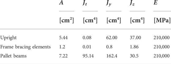
TABLE 1. Inertial properties of the cross-sections of the rack profiles.
The 3D finite element (FE) modeling of the racking system was carried out with Midas Gen software (Gen, 2021), using beam elements to simulate the elastic behavior of the uprights and pallet beams, and using truss elements to simulate that of the horizontal and diagonal bracing elements. The total mass per level, span, and frame (i.e., 2.1 t) was simulated with a single lumped mass positioned in its center of gravity, supported by a dummy substructure according to the indications of EN16681 (CEN 2016). This substructure, shown in Figure 2, allows to consider the effective height of the pallet’s center of gravity, and consists of four truss elements connecting the mass to the rack, having an adequate axial stiffness, such as not to significantly influence the modal characteristics of the structure and therefore the results of the seismic analysis. Lastly, in the case of the LLIS application, the isolation system was simulated using the classic Kelvin model (spring in parallel with a linear dashpot), connecting the dummy substructure with the lumped mass (Figure 2).
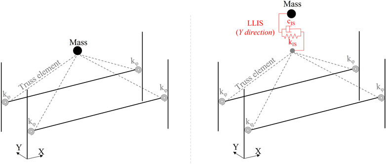
FIGURE 2. Pallet mass modeling with and without LLIS.
Among the main modeling assumptions, it is worth mentioning that the frame stiffness in the transverse direction was not reduced to take into account the actual stiffness of the base and brace-to-column connections and the loosening of the bolts. Then, the connections were modeled with their elastic rotational stiffness only, as their hysteretic behavior is significant in the down-aisle response of the rack, whereas the LLIS mainly affect the cross-aisle rack performance. Lastly, the warping effects (that might be evaluated according to Bernuzzi et al., 2014) were not considered in this study also due to the type of analyzed rack. Indeed, this study refers to double entry racks without spine bracing systems, which show less significant torsional modes than braced and more slender rack configurations. In general, these simplifications allowed making a more replicable study, omitting, for the sake of simplicity, all factors that do not significantly affect the comparative evaluation of racks with and without LLIS.
Figure 3 shows the main results of the modal analysis performed on the case study rack without LLIS. As can be seen, the first two vibration modes are in the down-aisle direction, while the third one is in the cross-aisle direction. For the purposes of this study, the frequency of the latter mode, defined as ωSDOF, is taken as a reference, as this mode corresponds to the single degree of freedom (SDOF) system which dynamically represents the racking in the cross-aisle direction, in which direction the LLIS acts.
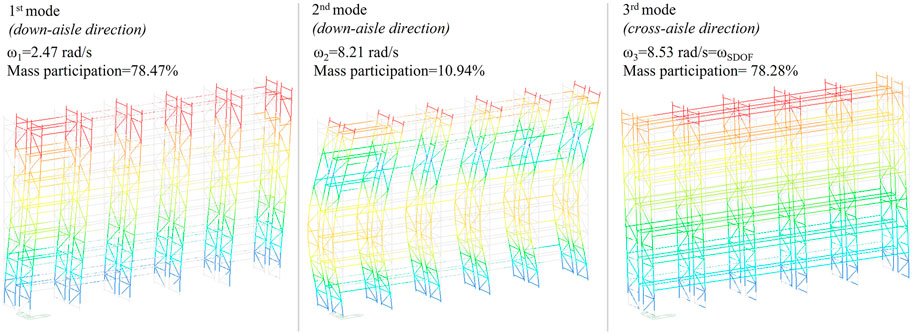
FIGURE 3. Modal analysis results of the case study rack without LLIS.
To evaluate the potential of the LLIS technique in improving the seismic response of the rack, six case studies were investigated, obtained by varying the position and quantity of the isolated pallet mass. In particular, three arrangements of the LLIS applied to a single load level (LL), i.e., the 7th, 5th, and 3rd LL, and three arrangements of the LLIS applied to two load levels (LLs), i.e., the 7-6th, 5-4th, and 3rd-2nd LLs, were analyzed, as shown in Figure 4. For each of the six case studies, the parameters of the LLIS were specifically optimized in the next Section, making it possible to rationally evaluate the effectiveness of this technique, as well as the trend of the optimal parameters, as a function of the position and quantity of the isolated mass.
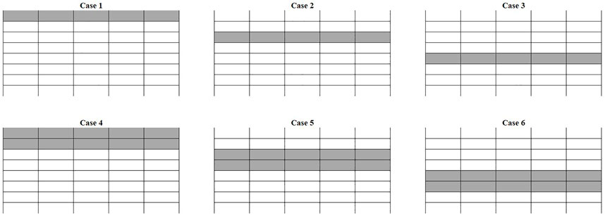
FIGURE 4. Arrangements of the pallet mass isolated by LLIS (in gray) analyzed in this study.
The rack structure with the LLIS can be dynamically represented through a simplified system with three lumped masses, as shown in Figure 5. In particular, the structure can be modeled with a 2 degree-of-freedom (DOF) system, one representing the part of the rack below the control system (ml) and the other representing the part above it (mU). The control system, i.e., the LLIS, is then dynamically described by a single DOF (mIS) connected to the lower DOF of the rack. As seen in Figure 5, the DOF representing the upper part of the rack and the DOF representing the isolated load levels are not directly connected to each other, but through the lower DOF of the rack. Therefore, mL and mU are the modal mass of the part of the rack below and above the LLIS, respectively, whereas kL and kU, and cL and cU are the respective modal stiffnesses and modal damping coefficients, calculated as described below. Instead, mIS is the total isolated mass, and kIS and cIS are the stiffness and damping coefficients of the isolation system.
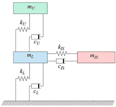
FIGURE 5. Simplified dynamic model of the rack structure with the LLIS.
The mass (M), damping (C) and stiffness (K) matrices of the 3DOF reduced-order system in Figure 5 are defined as:
The specific mass (m), damping (c) and stiffness (k) parameters are calculated as follows:
In Eq. 4, ML and MU are the mass matrices of the structural parts below and above the LLIS, respectively, and ϕ1,L and ϕ1,U are the respective first-mode eigenvectors in the cross-aisle direction, both normalized to one. In Eq. 5, ωL and ωU are the angular frequencies associated with the previous eigenvectors, and ξL and ξU are the related equivalent viscous damping ratios, assumed in this study equal to 3% (according to EN16681 CEN 2016, for the seismic design of steel racking).
To calculate the parameters m, c and k of the simplified dynamic model it is therefore necessary to carry out the modal analysis of the two structural parts of the rack separated by the isolated mass, evaluating them as independent and with a fixed base. The modal characteristics of interest are those relating to the first vibration mode in the cross-aisle direction. The values of ωL and ωU obtained from these analyzes and the associated values of mL and mU obtained through Eq. 4 are reported in Table 2 for the various case studies, as well as the mIS values corresponding to the total isolated pallet mass.
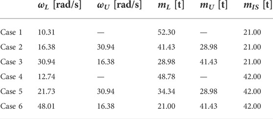
TABLE 2. Modal mass and angular frequency values to define the reduced order systems.
Instead, the angular frequency (ωIS) and the equivalent damping ratio (ξIS) of the isolation system (LLIS) are the two parameters to be optimized; they were calculated for all six case studies in Figure 4, by performing a structural optimization based on the reduced order system of Figure 5, as described in the following subsection.
For case studies 1 and 4, Table 2 does not provide the values of ωU and mU, as these parameters refer to the piece of frame above the last load level, and therefore tend to have very high and very low values, respectively, which are of little significance for this study. Indeed, this situation is equivalent to considering a 2DOF reduced-order system (eliminating mU), which is the system generally used in TMD optimization approaches.
Tuned Mass Damper (TMD) strategy is widely used in practice and investigated in the literature. Although for many years studies have focused on TMDs with low mass ratios (e.g., Warburton 1982), recently investigations have been directed towards TMDs with large mass ratios (non-conventional TMDs), also thanks to the growing interest in innovative applications (e.g., mega-sub-control-structures and inter-story isolation systems). Various methods of TMD optimization are currently available, which differ mainly in the pursuit of different objective functions. Some of these maximize the effect of TMD (e.g., Sadek, 1997) or the energy dissipated by it (e.g., Reggio and De Angelis 2015); others minimize a certain structural response (e.g., Moutinho 2012; Zhou et al., 2016; Pietrosanti et al., 2017) or functions that take into account multi structural responses (e.g., Yahyai et al., 2019); still, some rely on multi-objective approaches to minimize primary structure response while controlling isolation drift or acceleration (e.g., Bernardi et al., 2021).
Although the mass isolation strategy has also recently been investigated through the inter-story isolation technique for the retrofit of existing buildings (e.g., Faiella et al., 2020; Donà et al., 2022), it has not yet been thoroughly analyzed as a seismic mitigation technique for racking systems. Furthermore, to evaluate the effectiveness of the LLIS in various positions within the rack, it is necessary to refer (at least) to the 3DOF system shown in Figure 5, thus requiring an extension of the traditional TMD optimization approaches for buildings, these being based on a reduced order system with 2 DOFs only (one representing the primary structure and the other the TMD).
Using the matrices M, C and K shown in Eqs 1–3 it is possible to define the frequency response functions (FRFs) of the simplified 3DOF system. These functions describe the way in which sinusoidal input signals, of given excitation frequencies (ω), are transferred within the system in relation to the various structural response parameters. The FRF associated with the relative displacements [H(ω)] of the 3DOF system can be obtained according to the well-known Eq. 7, where τ is the unitary vector ([1, 1, 1] in this study).
The Power Spectral Density (PSD) function of a zero-mean Gaussian stochastic process, S(ω), is generally assumed to model the stochastic nature of the earthquake ground motion. Based on this seismic input model, the random vibration theory provides the covariance matrix in Eq. 8, where x is the vector of the relative displacements of the system. Cov [xxT] represents the power of the displacement response signal, and therefore its minimization can be used for structural optimization purposes. By introducing the simplified hypothesis that the seismic excitation can be represented also as a white noise process, the PSD function S(ω) is no longer dependent on ω and can be replaced by a constant S0. Based on this, the integral in Eq. 8 can be simplified with that in Eq. 9, where σ2 represents the variance of the relative displacements of the system. In this way, the optimization of the LLIS parameters (i.e., ωIS and ξIS), which are the variables of H(ω), can be based on the minimization of the variance σ2 (i.e., of the integral in Eq. 9).
In this study, a single objective optimization was adopted, assuming the relative displacement of the mass mU as a reference performance parameter. Indeed, this DOF represents the top racking portion, and therefore its displacement is the most representative of the maximum rack displacement, in the cross-aisle direction. Minimizing this displacement is significant for reducing the variations in axial stresses on the uprights, which are considerable in these very slender structures, and therefore for reducing the maximum stresses on structural elements in general. In particular, the chosen objective function (OFd) is defined in Eq. 10 and corresponds to the ratio between the displacement variance of mU and that of the equivalent SDOF of the rack without LLIS, in the cross-aisle direction (i.e., the third mode from the global modal analysis, see Figure 3). HU(ω) and HSDOF(ω) are clearly the FRFs of the mass mU and the equivalent SDOF system, respectively.
Therefore, the optimization problem (Jd) can be defined as in Eq. 11:
Figure 6 shows the results of the optimization carried out, in terms of optimal values of the objective function OFd (above) and of the isolation parameters ωIS and ξIS (below), as a function of the isolated levels and for all the analyzed case studies. The main observations are outlined below.
• By increasing the quantity of the isolated mass mIS (i.e., from Cases 1-2-3 to Cases 4-5-6), the structural performance of the rack improves, as the OFd values are reduced (see Figures 6A,B). Furthermore, the position of the isolated mass (i.e., the isolated level) is another determining factor for the dynamic control of the rack via LLIS, and therefore it influences the OFd values as expected.
• In particular, passing from Case 1 to Case 3 (mIS = 21 t per level, span, and frame), and from Case 4 to Case 6 (double mIS compared to the previous cases) it is possible to observe a slightly parabolic trend of the OFd values, with the lower values (i.e., better rack performances) obtained by isolating the upper levels of the rack. Then, it is interesting to note that the minimum values of OFd are obtained for Case 2 (mIS = 21 t) and Case 5 (mIS = 42 t), and that the expected minimum values fall between Cases 1-2 and Cases 4-5. This suggests that the best structural performance should be achieved by placing the LLIS in the upper part of the rack, but slightly lower than its top (i.e., the last load level).
• As regards the optimal parameters of the LLIS (see Figures 6C,D), it is observed that increasing the quantity of the isolated mass (i.e., from Cases 1-2-3 to Cases 4-5-6), the values of the angular frequency ωIS decrease and those of the damping ratio ξIS increase, tending towards less rigid and more dissipative isolation solutions, especially for the higher isolated levels.
• Furthermore, as regards the trend of the optimal parameters with respect to the positioning of the LLIS, a non-linear trend is noted, decreasing monotone for ωIS and increasing monotone for ξIS as the installation height of the LLIS increases. Therefore, the optimal application of LLIS requires more rigid and less dissipative isolation solutions as the position of the isolated levels decreases.
• Lastly, it can be observed that the optimal values of ωIS are comparable with the frequency of the main vibration mode of the rack in the cross-aisle direction (i.e., ωSDOF), which is the third global mode shown in Figure 3. In particular, ωIS is very similar to ωSDOF for cases with an intermediate position of the LLIS among those analyzed (i.e., Case 2 and Case 5). Therefore, the optimal isolation frequencies thus obtained are much higher than the frequencies of traditional base isolation systems, as the LLIS must interact with the rack structure to optimize its performance, actually behaving like a TMD.
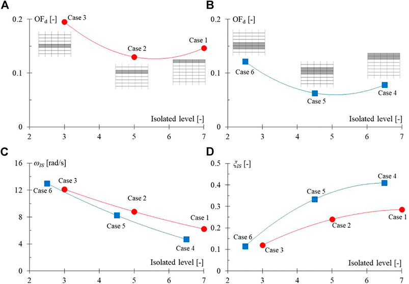
FIGURE 6. Optimal values of the OFd (A,B) and of the LLIS parameters, ωIS (C) and ξIS (D), as a function of the isolated levels and for all case studies.
The optimal values of the parameters ωIS and ξIS are also reported in Table 3 for the various case studies, together with the associated values of isolation stiffness kIS and linear viscous damping coefficient cIS of the LLIS.
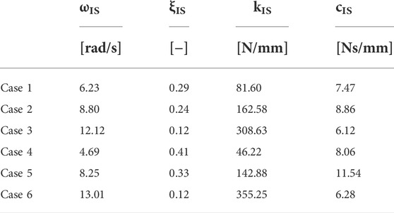
TABLE 3. Optimal values of the LLIS parameters.
Figure 7 compares the modal shapes obtained from the FE modeling of the rack with those derived from the reduced order model presented in subsection 3.1, considering all the optimized case studies (i.e., applying the LLIS with the optimal parameters in Table 3). Only the modal shapes that deform the structure are shown in these graphs, i.e., those associated with the second (Φ2) and third (Φ3) modes of the simplified model, thus leaving out (for clarity of representation) the first mode shapes (Φ1) associated with the LLIS displacement. Furthermore, the modal shapes from the FE models were obtained as an average among the eigenvectors of all the transverse frames of the rack, and are similar to the modal shapes of the second frame.
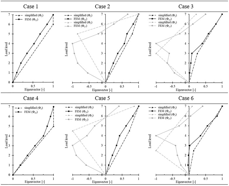
FIGURE 7. Comparisons between modal shapes of the FE and simplified models, for all optimized case studies.
Then, Table 4 compares the three angular frequencies of the simplified model (ω1, ω2 and ω3) with the corresponding ones from the FE modeling (ω/, ω// and ω///), which are associated with different global modes in the cross-aisle direction depending on the case study (as indicated in Table 4).
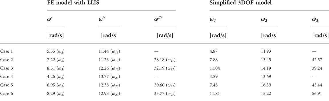
TABLE 4. Comparisons between modal frequencies of the FE and simplified models, for all optimized case studies (in brackets the global modes from the FE modal analysis).
In general, the comparisons shown in Figure 7 and Table 4 demonstrate, for all optimized case studies, the sufficient representativeness of the reduced order system compared to a more complex FE modeling, in terms of dynamic behavior, which is the basis for a correct optimization study. The greatest differences are found by comparing the values of ω3 with the corresponding values of ω/// in Cases 3 and 6, which share the lowest position of the LLIS. However, as seen by the previous optimization results (Figure 6) and as will be demonstrated by the subsequent validations in TH, these cases are the least interesting, i.e., those where LLIS is less effective in controlling the dynamic behavior of the rack. Indeed, these are also the only cases where the first mode in the cross-aisle direction (ω/) corresponds to the third global mode (as in the case without LLIS) instead of the second (as in the other cases with the LLIS).
Furthermore, some general considerations can be made on the frequency values shown in Table 4. For example, the values of ω/ are generally lower than ωSDOF (= 8.53 rad/s, see Figure 3), which is the first modal frequency in the cross-aisle direction without LLIS, and tend to ωSDOF by lowering the position of the LLIS (i.e., Cases 3 and 6). In addition, it is noted that as the isolated mass increases (i.e., from Cases 1-2-3 to Cases 4-5-6), the values of the first mode frequencies (ω/-ω1) decrease slightly. On the contrary, those of the second and third modes (ω//-ω2 and ω///-ω3), associated with structural deformation, slightly increase, since the total non-isolated mass is relatively reduced; although the frequencies increase only slightly, the related global mode numbers increase significantly (from 13 to 17 for Cases 1-2-3, to 23-27 for Cases 4-5-6), as the number of local modes increases.
The effectiveness of the LLIS was investigated for the case study structure through bidirectional time-history (TH) analyzes. All the selected cases with different positions of the LLIS (from Case 1 to Case 6) were analyzed under the seven seismic events reported in Table 5, and the average values of the maximum structural responses (i.e., displacements, accelerations, and upright stresses) due to each event were compared with the reference case without LLIS (see subsection 5.2).
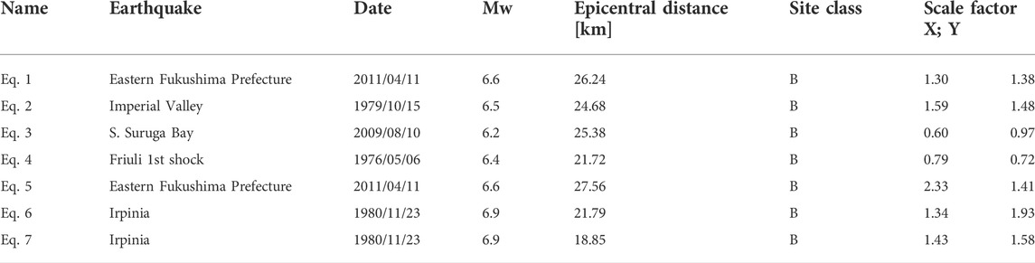
TABLE 5. Selected bidirectional natural records.
The seven bidirectional natural records were selected from the SIMBAD Database (Iervolino et al., 2009). These records were scaled to be compatible, on average, with the elastic design spectrum of EC8, Type 1 (CEN 2004), considering a bedrock acceleration (ag) of 0.25 g and a soil type B (i.e., a soil factor S = 1.2), and therefore a peak ground acceleration (PGA = ag·S) of 0.3 g (see Figure 8). In particular, compatibility is assessed according to MIT (2018, 2019); that is, the average of the SRSS spectra of the various events (obtained by the square root of the sum of the squares of the spectra of each component) is compatible with the “reference spectrum”, which is the elastic design spectrum scaled by √2 (considering conservatively the same design spectrum in both directions).
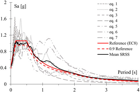
FIGURE 8. Acceleration response spectra (SRSS) of the selected events and EC8 reference spectrum.
The effectiveness of the LLIS is shown in this subsection through the maximum relative displacement profiles (Figure 9), the maximum absolute acceleration profiles of the pallet masses (Figure 10) and the maximum compressive and shear stresses on the uprights (Figure 11), averaged among the seven events analyzed, comparing the rack cases with optimized LLIS to the reference one without LLIS.
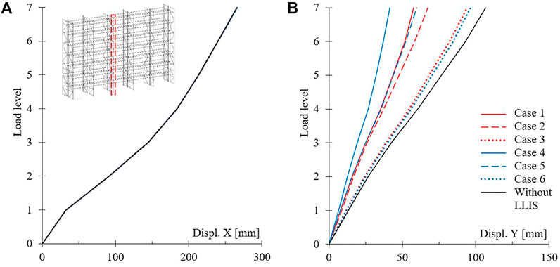
FIGURE 9. Mean values of the maximum absolute displacement profiles of the central frame: (A) down-aisle and (B) cross-aisle directions.
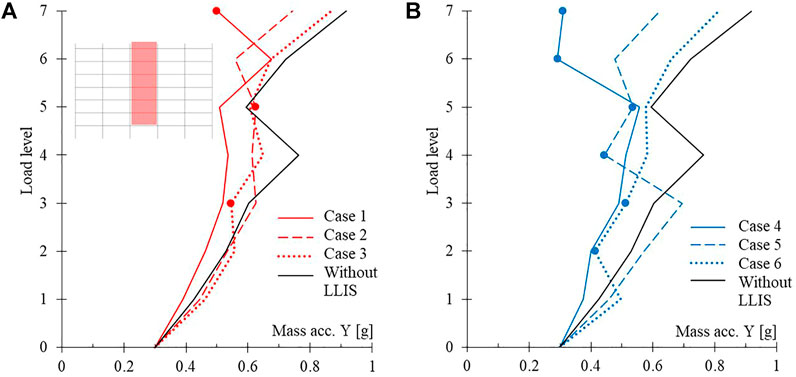
FIGURE 10. Mean values of the maximum absolute acceleration profiles of the pallet masses in the central span, in the cross-aisle direction: cases with (A) one and (B) two isolated load levels.
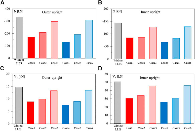
FIGURE 11. Mean values of the maximum compressive (N) and shear (VY) stresses on the outer (A,C) and inner (B,D) uprights of the central frame.
Figure 9 shows the mean values of the maximum absolute displacement profiles of the central frame (i.e., the most stressed), in both the down-aisle (Figure 9A) and cross-aisle (Figure 9B) directions, for all case studies. The main considerations on these results are listed below.
• Along the down-aisle direction (Figure 9A), the LLIS does not affect the structural response in terms of peak displacements, as expected.
• Instead, along the cross-aisle direction (Figure 9B), the adoption of LLIS significantly modifies the structural response, reducing the displacement profiles in all cases.
• Furthermore, it is noted (Figure 9B) how the position of the LLIS (indicated by the type of line) has a greater influence than the quantity of isolated mass (indicated by the different colors), and the best performance is achieved for the cases with the LLIS placed higher (i.e., Cases 1 and 4). Also, lowering the LLIS position reduces the beneficial effect of a larger amount of isolated mass (e.g., compare Cases 1-4 to Cases 3-6).
• Lastly, the reduction of the maximum displacement (at the rack top) in the Y direction is 46% with Case 1 and reaches 61% with Case 4.
Figure 10 shows the mean values of the maximum absolute acceleration profiles of the pallet masses in the central span, in the cross-aisle direction, for the cases with one (Figure 10A) and two (Figure 10B) isolated load levels, comparing them to those of the case without LLIS. The main considerations on these results are listed below.
• The acceleration profile of the case without LLIS has two peak values, one local at mid-height of the rack and one global (i.e., maximum acceleration) at the rack top, and this is justified by the specific higher vibration modes of this structural system.
• In general, the application of LLIS reduces the maximum seismic accelerations on the pallet masses, in the cross-aisle direction, for all cases investigated, even if more significantly in Cases 1 and 4, i.e., when the control system is positioned in the upper part of the rack. By lowering the control system in the central part of the rack (Cases 2 and 5), effective acceleration reductions in the central-upper part of the rack can still be obtained, in the face of slight increases in acceleration in the lower part of the rack, where it is in any case more contained. Instead, the application of LLIS in the lower part of the rack (Cases 3 and 6) is the least effective, as expected.
• Furthermore, the use of the LLIS with more isolated mass (Figure 10B) clearly allows greater control of these accelerations than in cases with less isolated mass (Figure 10A). The reduction of the maximum acceleration in the Y direction (registered at the rack top only for the case without LLIS) is 26% with Case 1 and reaches 39% with Case 4.
• Lastly, if the goal was to minimize accelerations on the pallet masses (e.g., for racking systems located in high seismic areas where safety against falling goods cannot be guaranteed in any other ways), it would be effective to isolate, individually or both, the load levels that register the acceleration peaks in the case without LLIS (e.g., for this case study rack, the fourth level in addition to the seventh).
Figure 11 shows the mean values of the maximum upright stresses, in terms of compression axial force (N) and shear force in the cross-aisle direction (VY), recorded at the base of the outer (Figures 11A,C) and inner (Figures 11B,D) uprights of the central frame. From these results the following considerations can be drawn.
• The LLIS technique allows to considerably reduce the axial compressive stresses at the base of the uprights, when the control system is positioned between the central part and the top of the rack (Figures 11A,B). The increase in the amount of isolated mass (i.e., from one to two isolated load levels) allows a greater reduction of these stresses, especially when the LLIS is positioned at the top of the structure; however, this further reduction in stresses is not proportional to the increase in isolated mass and therefore to the increase in the cost of the LLIS. The reductions obtained in the maximum values of N are 52% and 61% for the inner and outer uprights of Case 4, respectively, and 41% and 49% for the inner and outer uprights of Case 1, respectively.
• As regards the control of the shear forces of the uprights in the cross-aisle direction (Figures 11C,D), the same considerations just made for the axial forces still apply. However, unlike the latter, which are greater in the outer upright, the maximum shear forces are recorded at the base of the inner upright, where the first diagonal bracing of the frame is connected. The reductions obtained in the maximum values of VY are 49% for both the inner and outer uprights of Case 4 and 40% for those of Case 1.
Lastly, as regards the relative displacement of the optimized isolation systems, it is reduced by lowering the position of the LLIS and increasing the amount of isolated mass. In particular, the isolation drift for the various case studies, averaged among the maximum ones obtained from the seven seismic events, are: 10.0, 7.2 and 3.6 cm respectively for Cases 1, 2, and 3; 8.4, 6.2, and 2.9 cm respectively for Cases 4, 5, and 6. As expected, these values are smaller than the common design displacements of base isolation systems, performing the LLIS a different function.
Figure 12 shows the maximum axial stress state on all uprights, calculated with the “combined stress” criterion (see Midas Gen, 2021) that adds up the axial and bending contributions, for the reference case without LLIS (Figure 12A) and for Cases 1 and 4 (Figures 12B,C), under the Eq. 1 seismic event. The contour indicating this stress state was set in such a way as to highlight the structural parts that undergo greater stresses than the yield strength of these profiles (i.e., about 350 MPa), which are shown in blue and red (for tension and compression, respectively). This representation, which is not strictly a resistance check of the uprights, as the “combined stress” criterion is simplified and the structural checks are to be carried out according to the standard requirements (e.g., EN16681 CEN 2016, also evaluating the instability phenomena), it is however a useful reference for these comparisons.
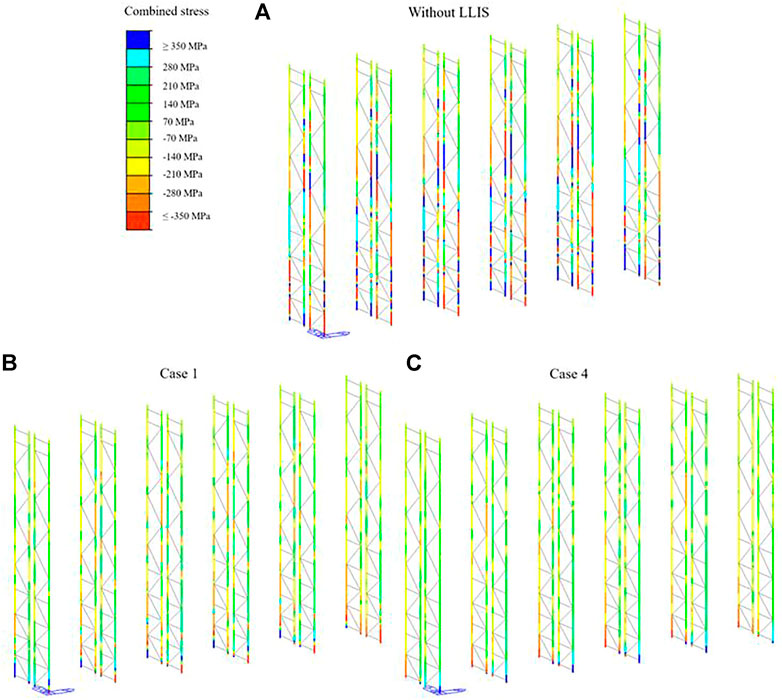
FIGURE 12. Maximum axial stress state on the uprights, under the Eq. 1 event: (A) without LLIS; (B) Case 1; (C) Case 4.
As can be seen from these figures, the use of LLIS is very effective in reducing the maximum stress state on the uprights. Indeed, in the case without LLIS, the Eq. 1 event (with a PGA of 0.3 g) caused a stress state that widely exceeds the yield strength within the racking (in particular, two yield zones are identified, one lower and one central-upper, in accordance with the deformation and acceleration profiles seen in Figures 9, 10). Instead, with Cases 1 and 4, these areas of excessive tension were limited to the elements of the first level only.
To provide a practical reference on the effectiveness of the LLIS technique, the Eq. 1 event was scaled, reducing the PGA, until reaching maximum stresses just below the yield strength of the profiles. The values of these reduced PGAs are 0.13 g for the case without LLIS, 0.21 g for Case 1, and 0.25 g for Case 4. Therefore, we can say that the LLIS allowed an increase in structural capacity of approximately 1.6 and 1.9 times, respectively for the case with one and two isolated levels.
The results of the optimization process shown in Figure 6 indicate that the best structural performance should be obtained by isolating the load levels slightly below the top level (although the differences in OFd values are small). However, the results of the parametric study in TH indicate that the best solutions, among those analyzed, are Cases 1 and 4 (i.e., with LLIS placed at the top of the rack). This is justified by the fact that the optimization carried out is based on the minimization of the variance rather than the peak of the structural response (displacement of m3), and takes into account the entire range of frequencies, thus resulting independent of the seismic input. On the contrary, the TH analysis results are clearly influenced by the specific frequency content of the selected events, and the reported values of the various performance parameters are the maximum ones recorded during the analysis (for a more effective representation), therefore associated with the peak responses. Furthermore, the approximation introduced using the reduced order model in the frequency domain analysis must also be considered, which would be greater in the case of racks such as that of the case study (with double frames, not very tall) than in more slender structures (with single frames and/or a high number of load levels).
To investigate this issue, Figure 13 shows the RMS (root mean square) values of two performance parameters, i.e., the axial compression force (N) on the outer upright and the shear force (VY) on the inner upright (both central), obtained for Cases 1 and 2 under the various seismic events and normalized to the respective values in the case without LLIS. For comparison purposes, a further case study was also analyzed, which implements the LLIS (optimized with the same proposed procedure) at the sixth level, resulting therefore intermediate between Cases 1 and 2; the associated dimensionless RMS values of N and VY are also plotted in Figure 13. The comparisons shown in this figure demonstrate that the best case can vary depending on the seismic event (and therefore its dynamic characteristics) and that the best performances, in terms of RMS, are often obtained with the intermediate case to those 1 and 2, according to the optimization results in Figure 6. Therefore, all this supports the adequacy of the proposed optimization approach, which is effective and simple to use, being independent of the random nature of the earthquake.
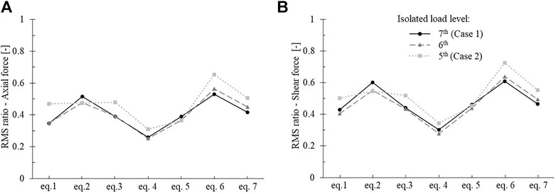
FIGURE 13. RMS values of (A) N and (B) VY, for the central uprights of the Cases 1, 2 and intermediate, normalized to the case without LLIS.
Previous results demonstrated the effectiveness of the LLIS technique in mitigating seismic excitations, even for applications with only one isolated LL. Therefore, the LLIS is very promising, and above all for the retrofit of existing, seismically inadequate racks, which otherwise would have to be replaced or used with partial filling. However, the final choice whether to adopt this technique is clearly subordinated to economic evaluations, or rather, to cost-effectiveness analyzes, which are beyond the scope of this work.
Considering the generally very low costs of industrial racking systems compared to traditional steel structures, a direct comparison between the costs of possible control devices and racks could lead to the conclusion that the LLIS is not economically viable, as well as for the base isolation systems (e.g., Simoncelli et al., 2020) and other mitigation systems (e.g., Shaheen and Rasmussen 2022) currently proposed for racks. However, their cost-effectiveness must be assessed taking into account all the expected seismic losses, both direct and indirect, mitigated by these systems, which strongly depend on the type of business as well as on the seismicity of the site and the vulnerability of the racking systems.
Therefore, the correct evaluation of the cost-effectiveness of these control systems is to be carried out through specific risk analyzes, including all the main cost and benefit factors. In addition to the issue of worker safety, which remains the first concern, and the direct seismic costs, associated with the destruction of the goods and the restoration of the storage systems damaged by the earthquake, indirect losses must also be considered; the latter arise from business interruption and other consequences of the disruption (e.g., Brown et al., 2015), and can be even more important than direct losses. Indeed, the high exposure of a production/storage plant does not depend on the value of the equipment and stored goods only, but also on the resilience of the business process (e.g., the possibility to implement business recovery strategies, such as relocation or production in outsourcing, see Donà et al., 2019).
In addition, many studies have been conducted over the past 20 years on new types of low-cost isolation or control devices, to be widely applied in developing countries or in non-industrialized areas (e.g., Kelly 1999; Van Engelen 2019; Tan et al., 2021). This research has contributed to the development of new high-performance yet cost-effective reinforcement materials, such as fiber reinforcements (e.g., Madera Sierra et al., 2018) and engineered plastics (e.g., Tan et al., 2014), as well as new dynamic control techniques, such as the tuned viscous mass damper with rotational inertia (e.g., Ikago et al., 2012) and the tuned mass damper with eddy current damping mechanism (e.g., Wang et al., 2012). All this therefore represents an excellent basis for devising innovative low-cost technologies suitable for LLIS. A first technology investigated for the LLIS, traditional but promising, is based on the RBRL system (Donà et al., 2017; Bernardi et al., 2022); this is a low-cost and easily adaptable system, consisting of a rolling support with rubber tracks and steel balls, capable of offering moderate dissipation during the rolling of the balls, and cylindrical rubber springs for re-centering the system.
Finally, it is worth mentioning that, especially for retrofit interventions, the LLIS technique could be more competitive than base isolation systems, due to a simpler and faster installation and to the fact that it is designed for a much lower load, although being still effective in containing accelerations on stored goods below safety thresholds for workers.
This paper presented an innovative seismic mitigation solution for industrial storage systems, namely the Load-Level Isolation System (LLIS), which consists of directly isolating the pallets in the cross-aisle direction, placing the isolation devices above certain load levels. The LLIS is based on the Tuned Mass Damper (TMD) strategy and takes advantage of the high payload of these structural systems, which is much greater than their self-weight. This control system has not yet been sufficiently analyzed in the literature, and among its major uncertainties are the amount of mass to be isolated (to prove effective) and its position within the structure.
Therefore, this paper investigated the LLIS through a case study pallet rack, by first optimizing the isolation parameters (i.e., isolation stiffness and damping ratio) for various arrangements of this system, considering cases with one or two isolated levels, and then evaluating the structural performance of the rack through Time-History (TH) analyses on Finite Element (FE) 3D models, applying a set of seven spectrum-compatible bidirectional events.
The proposed optimization procedure, defined in the frequency-domain and based on the minimization of the structural response variance, is an extension of the classical TMD approaches, which being based on a reduced order system with two degrees of freedom are not appropriate for investigating the rack with the LLIS. Indeed, for this structural system it is necessary to adopt an equivalent 3DOF system at least. The optimization carried out aimed at minimizing the displacement variance of the DOF (of the reduced order system) representing the upper part of the rack, i.e., the one above the LLIS. Indeed, this corresponds to minimizing the overall displacement of the rack and therefore the stresses on the uprights.
The results from the bidirectional TH analyses were shown in terms of maximum relative displacement profiles, maximum absolute acceleration profiles and maximum compressive (N) and shear (VY) stresses on the uprights, averaged among the seven events analyzed, comparing the cases with the optimized LLIS in various positions to the reference case without LLIS. Furthermore, the maximum axial stress state on the uprights was also shown, for the case without LLIS and for Cases 1 and 4 (i.e., with the LLIS applied at the top of the rack, in one and two load levels respectively), which allowed to obtain the best control of the structural performances.
From the analysis of the various results presented, the following conclusions can be drawn.
• The 3DOF reduced-order model, proposed for the LLIS optimization, adequately captures the dynamic characteristics of the rack in the cross-aisle direction, sufficiently approximating the main vibration modes and the related frequencies in that direction.
• According to the optimization study in the frequency-domain, the effectiveness of the LLIS in controlling the seismic performance of the rack increases as the isolated pallet mass increases; furthermore, the best performance of the rack should be achieved by placing the LLIS in the upper part of the structure, but slightly lower than the last load level.
• As regards the optimal parameters of the LLIS, the values of the angular frequency ωIS decrease and those of the damping ratio ξIS increase as both the quantity of the isolated mass and the installation height of the LLIS increase, tending in both cases towards less rigid and more dissipative isolation solutions.
• The results of the TH parametric analysis demonstrated the effectiveness of the LLIS technique, which significantly improved the seismic response of the rack in cross-aisle direction (and in the fully loaded service condition); on the other hand, as expected, the application of LLIS did not significantly influence the response along the down-aisle direction.
• The best seismic performance of the rack was obtained with the LLIS applied in the upper part of the structure, i.e., in Case 1 (with one isolated load level) and Case 4 (with two isolated load levels). In these cases, the maximum reductions in the peak seismic response were, respectively: 46% and 61% for the relative displacements; 26% and 39% for the mass absolute accelerations; 49% and 61% for the compressive stresses on the uprights; 40% and 49% for the shear stresses on the uprights. Furthermore, compared to the case without LLIS, an increase in structural capacity of approximately 1.6 and 1.9 times was estimated, respectively for Cases 1 and 4.
• Finally, by evaluating the stress response on the uprights in terms of RMS (root mean square) instead of peak, it was shown that the optimal position of the LLIS, among the upper levels of the rack, depends on the specific earthquake (i.e., its frequency content). For the selected events, the best level to install the LLIS turned out to be the one just below the top level, in accordance with the optimization study (which is independent of the seismic input). However, this issue remains worthy of investigation, especially for slender (i.e., tall, single-frame) storage racks.
Future works will be aimed at deriving general equations to estimate the optimal LLIS parameters, as a function of the isolated mass and its position. To this end, it is necessary to perform a parametric analytical study, introducing other variables and hypotheses in order to continuously represent the variation of the structural dynamic characteristics of the parts of the rack above and below the LLIS. The value ranges of the various parameters will have to be calibrated to represent a wide range of racking systems. Based on this study, a practical procedure for the design of the LLIS, of general validity, can therefore be defined.
Suggestions for future works also concern the cost-effectiveness assessment of these systems, which requires specific seismic risk analyzes, taking into account the main direct and indirect expected seismic losses, and therefore the actual exposure of the production/storage plants.
The original contributions presented in the study are included in the article/supplementary material, further inquiries can be directed to the corresponding author.
MD: Conceptualization, methodology, software, validation, writing—original draft, writing—review and editing. EB: Conceptualization, methodology, software AZ: Formal analysis, data Curation MC: Formal analysis, visualization FP: Supervision, writing—review and editing.
This study has been supported by the program “POR FSE VENETO 2014-2020,” through the project 2105-0031-14632019, with the title: “Innovative technologies for the mitigation of the effects of dynamic actions on storage/racks systems.”
The authors declare that the research was conducted in the absence of any commercial or financial relationships that could be construed as a potential conflict of interest.
All claims expressed in this article are solely those of the authors and do not necessarily represent those of their affiliated organizations, or those of the publisher, the editors and the reviewers. Any product that may be evaluated in this article, or claim that may be made by its manufacturer, is not guaranteed or endorsed by the publisher.
Álvarez, O., Maureira, N., Nuñez, E., Sanhueza, F., and Roco-Videla, Á. (2021). Numerical study on seismic response of steel storage racks with roller type isolator. Metals 11, 158. doi:10.3390/met11010158
Baldassino, N., and Zandonini, R. (2008). “Performance of base-plate connections of steel storage pallet racks,” in Proceedings of fifth international conference on coupled instabilities in metal structures (CIMS2008) (Sydney, Australia: Gregory J. Hancock Symposium), 119–130.
Bernardi, E., Donà, M., da Porto, F., and Tan, P. (2021). “Investigations on inter-storey seismic isolation as a technique for adding upper storeys,” in Proc. of 8th International Conference on Computational Methods in Structural Dynamics and Earthquake Engineering (COMPDYN), Athens, Greece (Greece: National Technical University of Athens (NTUA)).
Bernardi, E., Donà, M., Zonta, A., Ceresara, M., Mozzon, S., da Porto, F., et al. (2022). “Load-level isolation system for industrial racks: Evaluations on a case study structure,” in Proc. of the Eighth International Conference on Structural Engineering, Mechanics and Computation (SEMC 2022), Cape-Town, South Africa.
Bernuzzi, C., and Castiglioni, C. A. (2001). Experimental analysis on the cyclic behaviour of beam-to-column joints in steel storage pallet racks. Thin-Walled Struct. 39 (10), 841–859. doi:10.1016/s0263-8231(01)00034-9
Bernuzzi, C., Gobetti, A., Gabbianelli, G., and Simoncelli, M. (2014). Warping influence on the resistance of uprights in steel storage pallet racks. J. Constr. Steel Res. 101, 224–241. doi:10.1016/j.jcsr.2014.05.014
Bernuzzi, C., and Simoncelli, M. (2016). An advanced design procedure for the safe use of steel storage pallet racks in seismic zones. Thin-Walled Struct. 109, 73–87. doi:10.1016/j.tws.2016.09.010
Brown, C., Stevenson, J., Giovinazzi, S., Seville, E., and Vargo, J. (2015). Factors influencing impacts on and recovery trends of organisations: Evidence from the 2010/2011 canterbury earthquakes. Int. J. Disaster Risk Reduct. 14, 56–72. doi:10.1016/j.ijdrr.2014.11.009
Castiglioni, C. A., Drei, A., Mouzakis, H., and Kanyilmaz, A. (2018). Earthquake-Induced pallet sliding in industrial racking systems. J. Build. Eng. 19, 122–133. doi:10.1016/j.jobe.2018.05.004
CEN (European Committee for Standardization). (2005). Design of steel structures, Part 1-8: Design of joints. Eurocode 3, EN 1993-1-8 (Brussels: CEN).
CEN (European Committee for Standardization). (2004). Design of structures for earthquake resistance, Part 1: General rules, seismic actions and rules for buildings. Eurocode 8, EN 1998–1. (Brussels: CEN).
CEN (European Committee for Standardization) (2020). EN 15512 steel static storage systems – adjustable pallet racking systems – principles for structural design. Brussels.
CEN (European Committee for Standardization) (2010). EN 15878 steel static storage systems – terms and definitions. Brussels.
CEN (European Committee for Standardization) (2016). EN 16681 steel static storage systems – adjustable pallet racking systems – principles for seismic design. Brussels.
Dai, L., Zhao, X., and Rasmussen, K. J. (2018). Cyclic performance of steel storage rack beam-to-upright bolted connections. J. Constr. Steel Res. 148, 28–48. doi:10.1016/j.jcsr.2018.04.012
Dai, L., Zhao, X., and Rasmussen, K. J. (2017). Flexural behaviour of steel storage rack beam-to-upright bolted connections. Thin-Walled Struct. 124, 202–217. doi:10.1016/j.tws.2017.12.010
Donà, M., Bernardi, E., Zonta, A., Saler, E., and da Porto, F. (2022). “Assessment of the inter-story isolation technique applied to an existing school building,” in Proc. of the Eighth International Conference on Structural Engineering, Mechanics and Computation (SEMC 2022), Cape-Town, South Africa.
Donà, M., Bizzaro, L., Carturan, F., and da Porto, F. (2019). Effects of business recovery strategies on seismic risk and cost-effectiveness of structural retrofitting for business enterprises. Earthq. Spectra 35 (4), 1795–1819. doi:10.1193/041918eqs098m
Donà, M., Muhr, A. H., Tecchio, G., and da Porto, F. (2017). Experimental characterization, design and modelling of the RBRL seismic-isolation system for lightweight structures. Earthq. Eng. Struct. Dyn. 46, 831–853. doi:10.1002/eqe.2833
Drei, A., Rovere, L., Vayas, I., Jehin, D., Orsatti, B., Kanyilmaz, A., et al. (2016). Seismic behaviour of steel storage pallet racking systems (SEISRACKS2): Final report. (Brussels: European Commission, Directorate-General for Research and Innovation. Publications Office). https://data.europa.eu/doi/10.2777/686466
Faiella, D., Calderoni, B., and Mele, E. (2020). Seismic retrofit of existing masonry buildings through inter-story isolation system: A case study and general design criteria. J. Earthq. Eng. 26, 2051–2087. doi:10.1080/13632469.2020.1752854
FEMA460 (2005). Seismic considerations for steel storage racks located in areas accessible to the public. Washington D.C.: National Institute of Building Sciences, U.S. Department of Homeland Security, FEMA, NEHRP.
Ferrari, M. (2019a). Lokibase: The device for seismic isolation of pallet racking systems lokibase: Dispositivo per l’isolamento sismico di scaffalature metalliche portapallet. Costr. Met. 3, 82–91.
Ferrari, M. (2019b). Lokibase: The device for seismic isolation of pallet racking systems lokibase: Dispositivo per l’isolamento sismico di scaffalature metalliche portapallet. Costr. Met. 4, 111–122.
Filiatrault, A., Higgins, P. S., Wanitkorkul, A., Courtwright, J. A., and Michaele, R. (2008). Experimental seismic response of base isolated pallet-type steel storage racks. Earthq. Spectra 24 (3), 617–639. doi:10.1193/1.2942375
Franco, A., Massimiani, S., and Royer-Carfagni, G. (2015). Passive control of steel storage racks for parmigiano reggiano cheese under seismic accelerations. J. Earthq. Eng. 19, 1222–1259. doi:10.1080/13632469.2015.1049386
Gabbianelli, G., Francesco, C., and Nascimbene, R. (2020). Seismic vulnerability assessment of steel storage pallet racks. Ing. Sismica 37 (2).
Gusella, F., Lavacchini, G., and Orlando, M. (2018). Monotonic and cyclic tests on beam-column joints of industrial pallet racks. J. Constr. Steel Res. 140, 92–107. doi:10.1016/j.jcsr.2017.10.021
Huang, Z., Wang, Y., Zhao, X., and Sivakumaran, K. S. (2021). Determination of the flexural behavior of steel storage rack baseplate upright connections with eccentric anchor bolts. Thin-Walled Struct. 160, 107375. doi:10.1016/j.tws.2020.107375
Iervolino, I., Galasso, C., and Cosenza, E. (2009). Rexel: Computer aided record selection for code-based seismic structural analysis. Bull. Earthq. Eng. 8, 339–362. doi:10.1007/s10518-009-9146-1
Ikago, K., Saito, K., and Inoue, N. (2012). Seismic control of single-degree-of-freedom structure using tuned viscous mass damper. Earthq. Eng. Struct. Dyn. 41 (3), 453–474. doi:10.1002/eqe.1138
Jacobsen, E., and Tremblay, R. (2017). Shake-table testing and numerical modelling of inelastic seismic response of semi-rigid cold-formed rack moment frames. Thin-Walled Struct. 119, 190–210. doi:10.1016/j.tws.2017.05.024
Jovanović, Đ., Žarković, D., Vukobratović, V., and Brujić, Z. (2019). Hysteresis model for beam-to-column connections of steel storage racks. Thin-Walled Struct. 142, 189–204. doi:10.1016/j.tws.2019.04.056
Kelly, J. M. (1999). Analysis of fiber-reinforced elastomeric isolators. J. Seismol. Earthq. Eng. 2 (1), 19–34.
Kilar, V., Petrovčič, S., Koren, D., and Šilih, S. (2013). Cost viability of a base isolation system for the seismic protection of a steel high-rack structure. Int. J. Steel Struct. 13 (2), 253–263. doi:10.1007/s13296-013-2005-6
Kilar, V., Petrovčič, S., Koren, D., and Šilih, S. (2011). Seismic analysis of an asymmetric fixed base and base-isolated high-rack steel structure. Eng. Struct. 33 (12), 3471–3482. doi:10.1016/j.engstruct.2011.07.010
Madera Sierra, I. E., Marulanda, J., and Thomson, P. (2018). Matrix and reinforcement materials for low-cost building isolators: An overview of results from experimental tests and numerical simulations. Appl. Res. Technol. J. 16, 99–111.
Midas Gen (2021). On-line manual. Korea: MIDAS Information Technology Co, Ltd. http://manual.midasuser.com/EN_Common/Gen/905/index.htm.2.1.
MIT (Italian Ministry of Infrastructure and Transport) (2018). Update of the “Technical Standards for Constructions”. DM 2018/01/17, “S.O. No. 8 alla G.U. del 20 Febbraio 2018, No 32”. Rome, Italy. (in Italian).
MIT (Italian Ministry of Infrastructure and Transport). (2019). Instructions for the application of the «update of the “technical standards for constructions”». Circ. 2019/01/21 no. 7, “S.O. No. 5 alla G.U. del 11 Febbraio 2019, No. 35”, Rome, Italy (in Italian).
Moutinho, C. (2012). An alternative methodology for designing tuned mass dampers to reduce seismic vibrations in building structures. Earthq. Eng. Struct. Dyn. 41, 2059–2073. doi:10.1002/eqe.2174
Padilla-Llano, D. A., Eatherton, M. R., and Moen, C. D. (2016). Cyclic flexural response and energy dissipation of cold-formed steel framing members. Thin-Walled Struct. 98, 518–532. doi:10.1016/j.tws.2015.10.021
Padilla-Llano, D. A., Moen, C. D., and Eatherton, M. R. (2014). Cyclic axial response and energy dissipation of cold-formed steel framing members. Thin-walled Struct. 78, 95–107. doi:10.1016/j.tws.2013.12.011
Petrone, F., Higgins, P. S., Bissonnette, N. P., and Kanvinde, A. M. (2016). The cross-aisle seismic performance of storage rack base connections. J. Constr. Steel Res. 122, 520–531. doi:10.1016/j.jcsr.2016.04.014
Pietrosanti, D., De Angelis, M., and Basili, M. (2017). Optimal design and performance evaluation of systems with tuned mass damper inerter (TMDI). Earthq. Eng. Struct. Dyn. 46, 1367–1388. doi:10.1002/eqe.2861
Proença, J., Rosin, I., and Calado, L. (2009).Storage racks in seismic areas. (Brussels: European Commission, Directorate-General for Research and Innovation. Publications Office). https://data.europa.eu/doi/10.2777/60886.
Reggio, A., and De Angelis, M. (2015). Optimal energy-based seismic design of non-conventional Tuned Mass Damper (TMD) implemented via inter-story isolation. Earthq. Eng. Struct. Dyn. 44, 1623–1642. doi:10.1002/eqe.2548
Sadek, F., Mohraz, B., Taylor, A. W., and Chung, R. M. (1997). A method of estimating the parameters of tuned mass dampers for seismic applications. Earthq. Eng. Struct. Dyn. 26 (6), 617–635. doi:10.1002/(sici)1096-9845(199706)26:6<617::aid-eqe664>3.0.co;2-z
Shaheen, M. S. A., and Rasmussen, K. J. R. (2022). Development of friction-damped seismic fuses for steel storage racks. J. Constr. Steel Res. 192, 107216. doi:10.1016/j.jcsr.2022.107216
Simoncelli, M., Tagliafierro, B., and Montuori, R. (2020). Recent development on the seismic devices for steel storage structures. Thin-Walled Struct. 155, 106827. doi:10.1016/j.tws.2020.106827
Tagliafierro, B., Montuori, R., and Castellano, M. G. (2021). Shake table testing and numerical modelling of a steel pallet racking structure with a seismic isolation system. Thin-Walled Struct. 164, 107924. doi:10.1016/j.tws.2021.107924
Tan, P., Liu, H., and Donà, M. (2021). Unconventional elastomeric isolators reinforced with engineered plastic plates: Compressive failure analysis. Int. J. Solids Struct. 230–231, 111163. doi:10.1016/j.ijsolstr.2021.111163
Tan, P., Xu, K., Wang, B., Chang, C. M., Liu, H., Zhou, F. L., et al. (2014). Development and performance evaluation of an innovative low-cost seismic isolator. Sci. China Technol. Sci. 57 (10), 2050–2061. doi:10.1007/s11431-014-5662-6
Van Engelen, N. C. (2019). Fiber-reinforced elastomeric isolators: A review. Soil Dyn. Earthq. Eng. 125, 105621. doi:10.1016/j.soildyn.2019.03.035
Wang, Z. H., Chen, Z. Q., and Wang, J. H. (2012). Feasibility study of a large-scale tuned mass damper with eddy current damping mechanism. Earthq. Eng. Eng. Vib. 11 (3), 391–401. doi:10.1007/s11803-012-0129-x
Warburton, G. B. (1982). Optimum absorber parameters for various combinations of response and excitation parameters. Earthq. Eng. Struct. Dyn. 10 (3), 381–401. doi:10.1002/eqe.4290100304
Yahyai, M., Zebarjad, L., Head, M., and Shokouhian, M. (2019). Optimum parameters for large mass ratio TMDs using frequency response function. J. Earthq. Eng., 1–20. doi:10.1080/13632469.2019.1624228
Yin, L., Tang, G., Li, Z., Zhang, M., and Feng, B. (2018a). Responses of cold-formed steel storage racks with spine bracings using speed-lock connections with bolts I: Static elastic-plastic pushover analysis. Thin-Walled Struct. 125, 51–62. doi:10.1016/j.tws.2018.01.005
Yin, L., Tang, G., Li, Z., and Zhang, M. (2018b). Responses of cold-formed steel storage racks with spine bracings using speed-lock connections with bolts II: Nonlinear dynamic response history analysis. Thin-Walled Struct. 125, 89–99. doi:10.1016/j.tws.2018.01.002
Yin, L., Tang, G., Zhang, M., Wang, B., and Feng, B. (2016). Monotonic and cyclic response of speed-lock connections with bolts in storage racks. Eng. Struct. 116, 40–55. doi:10.1016/j.engstruct.2016.02.032
Zhao, X., Dai, L., and Rasmussen, K. J. (2018). Hysteretic behaviour of steel storage rack beam-to-upright boltless connections. J. Constr. Steel Res. 144, 81–105. doi:10.1016/j.jcsr.2018.01.006
Keywords: pallet racking system, load-level isolation system, tuned mass damper, frequency response function, structural optimization, time-history analysis
Citation: Donà M, Bernardi E, Zonta A, Ceresara M and da Porto F (2022) Effectiveness of load-level isolation system for pallet racking systems. Front. Built Environ. 8:944026. doi: 10.3389/fbuil.2022.944026
Received: 14 May 2022; Accepted: 11 July 2022;
Published: 05 August 2022.
Edited by:
Roberto Nascimbene, IUSS—Scuola Universitaria Superiore Pavia, ItalyReviewed by:
Giammaria Gabbianelli, University of Pavia, ItalyCopyright © 2022 Donà, Bernardi, Zonta, Ceresara and da Porto. This is an open-access article distributed under the terms of the Creative Commons Attribution License (CC BY). The use, distribution or reproduction in other forums is permitted, provided the original author(s) and the copyright owner(s) are credited and that the original publication in this journal is cited, in accordance with accepted academic practice. No use, distribution or reproduction is permitted which does not comply with these terms.
*Correspondence: Francesca da Porto, ZnJhbmNlc2NhLmRhcG9ydG9AdW5pcGQuaXQ=
Disclaimer: All claims expressed in this article are solely those of the authors and do not necessarily represent those of their affiliated organizations, or those of the publisher, the editors and the reviewers. Any product that may be evaluated in this article or claim that may be made by its manufacturer is not guaranteed or endorsed by the publisher.
Research integrity at Frontiers
Learn more about the work of our research integrity team to safeguard the quality of each article we publish.