 Julia Hopkins
 Nicholas Lutsko2
95% of researchers rate our articles as excellent or good
Learn more about the work of our research integrity team to safeguard the quality of each article we publish.
Find out more
ORIGINAL RESEARCH article
Front. Built Environ. , 09 June 2022
Sec. Coastal and Offshore Engineering
Volume 8 - 2022 | https://doi.org/10.3389/fbuil.2022.885298
This article is part of the Research Topic Natural and Nature-Based Features for Flood Risk Management View all 17 articles
Nature-based solutions (NBS) have been broadly defined in coastal resilience as the restoration of natural environments or as civil infrastructure with natural elements, with examples ranging from marsh restoration and new oyster beds to artificial reefs and living shorelines. The multiplicity of NBS types makes it difficult to quantify and model their effectiveness as a whole in coastal flood reduction and environmental co-benefits. Specific types of NBS operate under a variety of physical and ecological regimes: oyster beds care about the benthic environment and can be modeled as bed roughness elements, while living shorelines are a combination of emergent/submerged vegetation elements located in the dynamic swash zone. As such, NBS cannot be investigated as a monolith and their evaluation will be intervention-specific. Here, we present the evaluation of an engineered NBS called the Emerald Tutu, a series of interlinked vegetated mats which leverage known physical and ecological properties of marsh environments and combine them in networked formats for rapid deployment around shoreline environments. The Tutu takes inspiration from marsh canopies, but aims to transport the physical protection of these canopies to urban areas using the wave attenuation properties of floating vegetation elements and network effects. Prototype Tutu units were deployed in the OH Hinsdale Wave Lab at Oregon State University in summer 2021 to test the physical efficacy of the mat networks. The results show the effect of network arrangement, mat canopy size, and Tutu unit density on wave attenuation. We show how these results can be used to design the Tutu for a variety of coastal environments, and discuss the impact of submerged vegetation dynamics on Tutu effectiveness and what research gaps remain for the implementation of these kinds of engineered NBS.
Coastal environments and coastal communities are vulnerable to climate change impacts such as sea level rise, higher rates of erosion, and more intensified storms. These effects will increase flooding and expose more inhabited land to the ocean, damaging livelihoods, infrastructure, and ecological systems. Historically, issues of erosion and flooding have been mitigated in populated areas using “hard” infrastructure such as seawalls, groins, jetties, and other concrete- or steel-based structures (Smallegan et al., 2016; Morris et al., 2018). Eroding beaches along more natural coasts have been managed with nourishments as well as hard structures to encourage sand accumulation (van Duin et al., 2004; Stive et al., 2013; de Schipper et al., 2020). These traditional measures are being challenged by the uncertain impacts of climate change both in terms of sea level rise and weather patterns, as hard infrastructure is difficult to design or adapt to uncertain climate futures (Sutton-Grier et al., 2015). Nature-based solutions (NBS) offer alternative coastal resilience measures which have the potential to adapt to a changing climate.
NBS leverage aspects of the natural environment to buffer against negative effects of climate change. Coastal examples include efforts to restore marshes and mangrove forests (Quartel et al., 2007; Howard et al., 2017), and designs to deploy oyster reefs near urban areas (Morris et al., 2018). These examples attempt to build natural barriers of vegetation and benthic organisms between ocean forces (e.g., storm waves) and coastal communities. The physical premise for the effectiveness of these NBS is reasonably well-understood. Research into seagrass and mangrove forests shows that their effectiveness at damping wave energy comes from forcing complex vortical structures in the landward flow (Quartel et al., 2007; Crooks et al., 2011; Howard et al., 2017; Bergstrom et al., 2019; Menendez et al., 2020). Similarly, submerged oyster reefs and even submerged artificial reefs operate under the principle of enhanced bed roughness, increasing the friction between the bed and incoming waves or surge and reducing the energy of the flow before it reaches the shoreline (Morris et al., 2018). NBS are organic, living entities and as such have the potential to adjust to, and mitigate, climate change effects like sea level rise and storm intensity.
These natural types of NBS require a significant amount of space to be effective: mangrove forests and marshes demand shoreline real estate and the research into the footprint of an oyster reef needed to fully damp a storm wavefield is ongoing, but likely in the range of hundreds of meters to kilometers. In urban environments, the necessary real estate may not be readily available. This presents both a challenge and an opportunity to develop new types of NBS which are engineered to incorporate natural features in infrastructure designed for urban environments and flexible enough to evolve as the climate changes. The research presented here focuses on one such engineered NBS, the Emerald Tutu, as a model for how these types of solutions may operate and be evaluated for effective deployment in urban environments.
The Emerald Tutu consists of floating vegetated mats that are interlinked and anchored to the seafloor to provide a modular network of protective canopies encircling urban coastlines (Figure 1). The Tutu was developed through collaboration between landscape architects, coastal engineers, climate scientists, and water resource specialists to provide flood mitigation as well as ecological and social co-benefits to coastal communities. Floating wetlands similar to the Tutu have been used thus far as individual elements in quiescent water bodies such as wastewater treatment plants, rivers, and lakes to improve water quality (Faulwetter et al., 2011; Hwang and LePage, 2011; Bi et al., 2019). Isolated vegetated canopies seeded with emergent and submerged vegetation have also been tested in laboratory conditions, showing that vegetated canopies have the potential to damp incident wave energy (Chen et al., 2016; Zhu et al., 2021). The Tutu extends the floating canopy concept to increase robustness for exposed coastal conditions, and adds the element of network effects to damp storm wave energy.
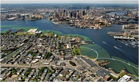
FIGURE 1. Aerial view of a rendering of the Emerald Tutu (green circles) surrounding East Boston, MA. The white strips represent walkways through the mat which can be used by community members during calm weather.
The modular, floating nature of the Tutu design makes it ideal for deployment in areas where land real estate is difficult to use for coastal resilience. Its structural reliance on vegetation provides benefits to native plants and animals. However, the efficacy of the Tutu, or any similarly engineered NBS, needs to be carefully evaluated to determine its optimal design and deployment. At present, there are few site-specific examples of NBS performance and few studies which dive into the physical underpinnings of NBS operations to the extent that coastal scientists could use them to improve existing numerical models or create new models which accurately predict and quantify NBS effects (Chen et al., 2016; Sarabi et al., 2019; Chausson et al., 2020; Zhu et al., 2021). The Emerald Tutu is an opportunity to begin to bridge this knowledge gap between NBS ideation and performance.
In this paper, we report on initial tests of the physical effectiveness of the Tutu system. The objective of the study was to evaluate the efficacy of an interlinked network of floating mats in attenuating nearshore waves. We designed and built scaled physical analogues of the Tutu and observed their behavior under a variety of wave conditions in the Natural Hazards Engineering Research Infrastructure (NHERI) O.H. Hinsdale Wave Basin at Oregon State University. In particular, we tested the hypothesis that the attenuation of waves owing to a network of Tutu mats is a function of mat network geometry, wavelength, and mat density. Our results show the existence of a relationship between network geometry and incident wavelength, as opposed to network density and incident wave conditions. Further, our results support the idea that a truly effective NBS requires a significant footprint along either the shoreline or the nearshore environment, suggesting that approaches to NBS which incorporate multiple, tiered solutions may be optimal for urban coastal communities in the face of climate change.
This initial study tests the physical behavior of the Emerald Tutu, focused on the abilities of individual mats and the network as a whole to damp incident wave energy. The facility we used was the NHERI O.H. Hinsdale Directional Wave Basin at Oregon State University, a lab capable of simulating both regular and random wavefields for a range of heights and directions. The basin is 48.8 m by 26.5 m in the horizontal, and 2.1 m deep with a 1:10 sloped steel beach for wave energy dissipation set opposite a series of wave paddles (Figure 2). The basin’s capabilities, most importantly its width, make it an ideal setting to focus on understanding the wave dissipation properties of a floating dense mat network.
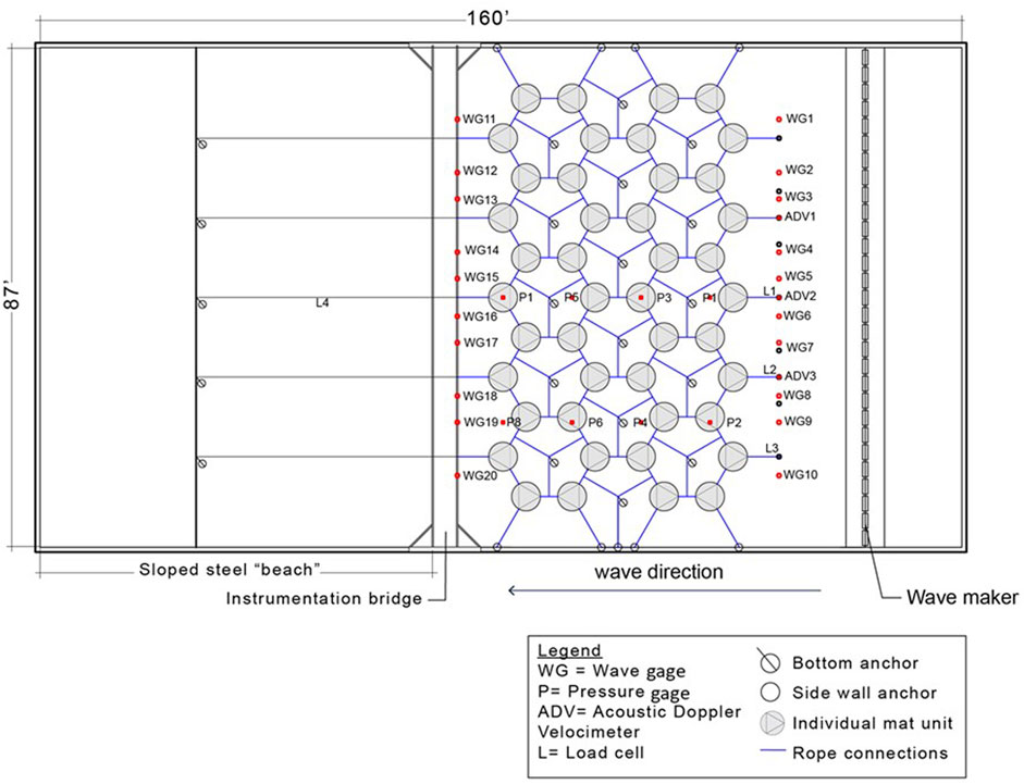
FIGURE 2. Aerial view of the “sparse” Tutu network in the wave basin, with the wavemaker on the right and the beach on the left. The 5 ft diameter Tutu mats are show in grey, the dark blue lines are nylon connections between the mats and the anchors to the beach and side walls, empty circles with lines show bottom anchors, and the red dots show the location of instruments measuring hydrodynamic properties. The 1:10 sloped beach begins to the left of the instrumentation bridge. The instruments are labeled as shown in the legend to the bottom right.
We deployed a scaled physical replica of the Tutu network according to the spatial limitations of the lab setup. The mats were designed to be half the diameter of what we would expect in a field deployment (thus 1.5 m diameter in the lab). We built and deployed 44 mats in the basin (Figure 2) to allow for sufficient space between the wavemaker, the network, and the beach slope for wave development. The mats consisted of canvas shells, stuffed with discarded wood fragments from a nearby forestry service in Corvallis, OR, and a large piece of pink insulation foam (cut into a hexagon with 1.4 m length diagonals) for buoyancy (Figure 3). The wood fragments are used in the Tutu design because they are an abundant, reliable, cheap, and ubiquitous biomass sources (and wood lignin takes longer to break down than biomass alternatives). The wood fragments also have a large surface area, which for the field means that they get covered with slime and algae and jumpstart the food chain to encourage vegetation. In the real mat design, we mix sharp wood fragments with coconut fiber (Figure 3), which makes a substrate able to hold its shape and encourages Spartina roots to grow in these nooks.
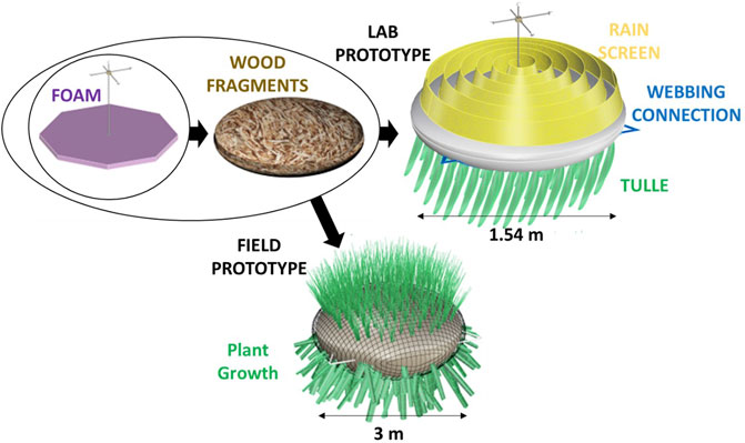
FIGURE 3. Flow chart of the components of the wave basin prototype and the field prototype. Both contain foam (purple) and wood fragments from local forestry services (brown), but the Field Prototype (bottom) is made from burlap and coconut fiber to encourage natural plant growth (e.g., Spartina) while the Lab Prototype (top right) is made from lightweight canvas, a rain screen sewn to the top (yellow), strands of tulle sewn to the bottom (green), and webbing also sewn to the bottom in a triangle with the corners stick out (blue) to provide connection points to other mats and basin anchors.
For the lab prototype, the canvas shells had two components, a top and a bottom circular piece stitched together at the edges by hand. The outer canvas shell and the inner wood fragments are identical to the proposed field design. The buoyant insulation foam made the draft of each unit (0.3 m draft for 150 lbs) such that only the top of the yellow canvas shell was exposed once water had soaked into the mats (see Figures 3, 4E,F).
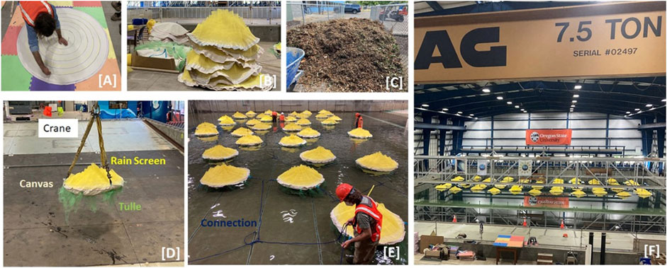
FIGURE 4. Construction of the individual mats and the network, from (A) cutting and marking canvas to 5 ft diameter, (B) sewing rain screen (yellow) to the top canvas piece and tulle (light green) with a webbing triangle (light blue) to the bottom piece, (C) using wood discard fragments to stuff the units, (D) lifting a stuffed and sewn unit into the basin where (E) it is tied to other units using nylon rope (dark blue) to finally set the (F) completed network in 1.37 m of water depth.
Material was sewn onto the canvas shells to represent light vegetation, with a rigid and porous rain screen sewn on the top and flimsier, more flexible strands of tulle sewn to the bottom (Figure 3). The rains screen was chosen as an analog for Spartina grass vegetation because: 1) its suppleness matches marsh grass, 2) it is porous/fiber-based and dense (which makes it omnidirectional), and 3) is available in a “surface” (roll) format which made it easy to sew onto the top of the units. The submerged vegetation (tulle) was chosen so it could move/sway in a similar manner to actual seaweed strands. Also sewn to each bottom piece were triangles of webbing that served as anchor points for the network connections (blue in Figures 3, 4E).
The mats were anchored together using nylon rope (blue in all figures) that was spliced together at webbing anchor points on the mats and eye bolts between mats set into the floor of the basin and the basin walls. The webbing anchor points on the mats were from three corners of webbing triangles that were otherwise sewn into the bottom half of the canvas shell (the corners extended beyond the shell diameter, see Figure 3). Nylon rope was chosen to connect the mats and the wave basin anchors because it has similar resistance to tension as rigid shipping line, which we used in the field deployment, while being simpler to work with in the lab.
We tested wave conditions within the range of what was feasible given the facility and the strength of connections between the mats. The weak point in the mat construction was the hand-sewn canvas around the webbing anchors, where the bulk of the force on the mats was being applied by incident waves. This limited the intensity of waves and meant we discarded our highest wave height of 0.5 m over the duration of the experiment. Despite this, we were able to test a representative range of waves (Table 1), in both regular and random regimes. The conditions were repeated for two mat network configurations, one where the mats were spread out in a “sparse” configuration (S, Table 1 and Figure 5) and another where the mats were pulled together to eliminate the spacing between them in a “dense” configuration (D, Table 1 and Figure 5). The networks are arranged in hexagons according to the Tutu design for the field, intended to accommodate multi-directional wave fields. We chose the sparse configuration to fill the possible width provided by the wave basin (0.915 m spacing between the mats), and the dense configuration to test the extreme of no space between the mats (0 m spacing between the mats).
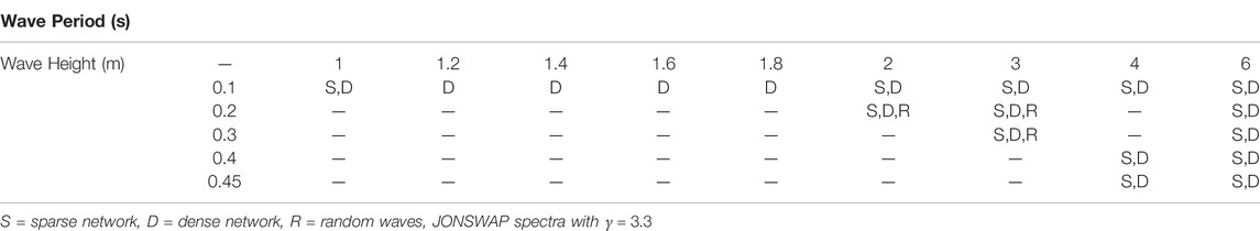
TABLE 1. List of wave conditions tested on the 50% scaled Tutu mat network.
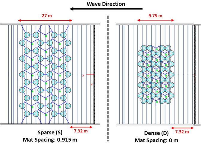
FIGURE 5. Aerial view sketches of the two mat network configurations (Sparse, left, and Dense, right) inside the basin. The vertical lines represent divots in the bottom of the basin where eyelets (light green) were placed as anchor points. The spacing between these lines is 1.22 m. The wavemaker is to the right, the beach is to the left. The dark blue lines are interconnections between the mats (circles), with the light blue lines within the circles indicating the webbing sewn into the canvas.
The wave basin was outfitted with a number of instruments to track mat behavior and hydrodynamic conditions before and after the mat network (Figure 2). The primary measurements of interest for this paper are: 1) the wave attenuation measured by wave gages set before and after the mat network, and 2) the pressure gages scattered within the network. As seen in Figure 2, there were ten wave gages deployed between the mats and the wavemaker, and ten deployed between the mats and the beach. The first set of gages (wavemaker-to-mats) were deployed on steel struts anchored to eyebolts in the bed of the basin. The second set of gages (mats-to-sloped beach) were deployed on the gantry (instrument bridge) above the basin and suspended in the water. The eight pressure gages deployed within the network were placed at the bed along the unistrut supports running alongshore relative to the wave direction. All gages collected data at 100 Hz.
In addition to the tests conducted with sparse and dense mat networks (Table 1), we ran all of the “Dense” wave conditions for a basin with no mats. This gave us a baseline for wave behavior measured by the gages and the pressure sensors, and also allowed us to determine wave reflectance from the sloped beach and the side wall to remove any confounding factors in our analysis.
Initial results focus on the wave attenuation properties of the mat network. Regular wave tests were about 3 min long to allow for steady state in the basin. The timeseries of wave height and pressure measured within these 3 minutes was analyzed at each wave and pressure gage location to determine time-averaged wave behavior in space around the mat network for the full set of tests. The signals were analyzed with Fourier transforms to isolate the wave height (water oscillation amplitude) and wave period. Wavelengths were calculated using the intermediate depth wave dispersion relationship
We calculated the time-averaged energy of the waves at each gage location using
The wave gages before and after the mat network were compared to determine the attenuation for the network as a whole. Figure 6 demonstrates the signal before and after the mats at the centerline of the flume. The mat network performance depends on the incident wave conditions.
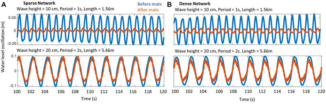
FIGURE 6. Sample wave gage signals from the sparse network (A) and the dense network (B) for wave heights of 10 cm (top) and 20 cm (bottom). Incident wave conditions (blue) are higher than wave conditions after the network (red) but the damping effect of the network changes depending on the wave conditions and network configuration. The gages used here are located in the middle of the basin in the direction of wave propagation.
To be consistent in the analysis despite the different spatial extents of the network configurations (the sparse network extends to the edges of the tank, dense does not, see Figure 5), and to reduce erroneous measurements owing to wall effects, we focus on the gages aligned with the center of the network in the cross-shore in this analysis. The resulting wave attenuation patterns are shown in Figure 7, averaged over the three gages closest to the centerline of the basin in the direction of wave propagation. Figure 7A shows the attenuation compared to the wave steepness, a non-dimensional quantity calculated by dividing wave height by wavelength (calculated using the dispersion relationship). Figure 7B shows the same attenuation broken up between wavelength (x-axis, Figure 7B) and wave height (colors, Figure 7B).
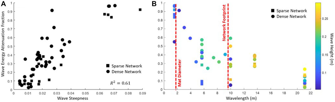
FIGURE 7. (A) Wave steepness (x-axis) versus wave attenuation (y-axis) where 0 is no attenuation and 1 is full attenuation. Symbols represent the network configuration (square is sparse, circles are dense). (B) Wavelength (x-axis) versus wave attenuation (y-axis). Color indicates wave height (yellow is higher, blue is lower) and symbol represents the network configuration (square is sparse, circles are dense). The red dotted lines indicate the size of the mat diameter and of the network footprint in the direction of wave propagation (specifically for the dense network configuration).
The pressure sensors were strategically located throughout the mat network and occasionally returned a staccato signal indicating that they were not measuring perfect wave shapes. This signal is owing to the fact that the pressure gages were measuring both pressure from the water and occasionally pressure from a mat passing over the gage in response to wave action. As a result, a point-by-point comparison in time between the pressure gages was not possible, and we focused on relating the incident wave conditions to the spatial variance in the average wave measurements from the pressure sensors (how much the wave energy kept moving through the network). A low variance suggests that either the wave energy did not change throughout the mat network, or that it was all dissipated by the initial line of mats. Figure 8A shows that the variance in space has a dependency on wave height more so than wavelength. Similarly, the velocity measurements from the ADVs placed before the mat network show a relationship between velocity and wave height, as expected from linear wave theory since larger waves generate higher wave orbital velocities (Figure 8B).
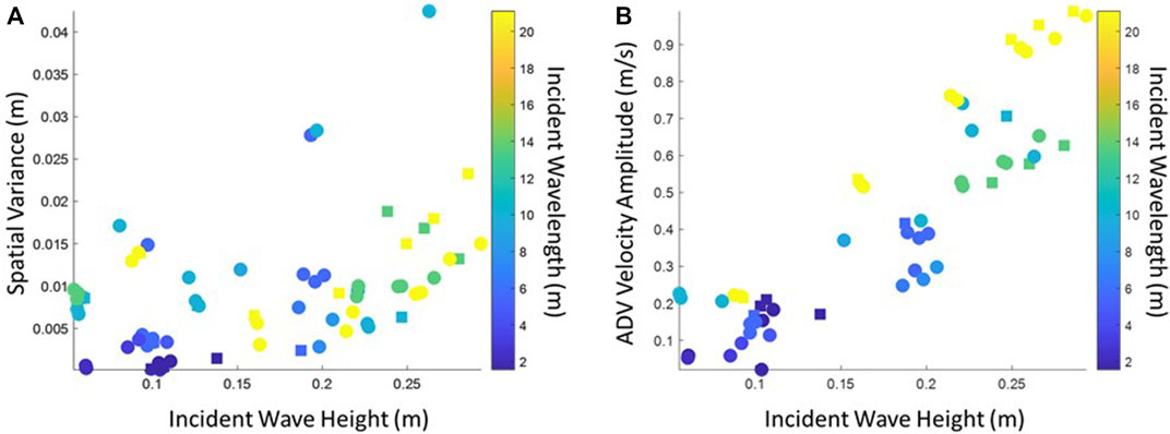
FIGURE 8. (A) The spatial variance of wave height within the mat network as measured by the pressure gages (y-axis), and (B) wave height (x-axis) versus velocity (y-axis) measured before the mats by the ADV. Color shows the associated wavelength with lighter colors indicating longer waves, and darker colors indicating shorter waves. Higher incident wave height translates to higher velocities before the mats, as expected, and higher variance of pressure within the mat network indicates greater changes in wave height as the waves penetrate the network.
We used the pressure sensors and the wave experiments run without Tutu units in the basin to calculate wave reflection for all the regular wave conditions, following the method of using three gages in the direction of wave propagation as outlined in Isaacson (1991). This method shows that reflection increases as the wavelength increases, yet the reflection coefficient remains less than 0.1 for most wave conditions tested. Experiments with reflections over this threshold were not considered in our analysis, hence the results presented here are not contaminated by significant wave reflection either before or after the mat network.
The three random wave tests using the Dense configuration were run for 10 minutes to allow for a fully random sea state. The results from the wave gage measurements in the random tests were analyzed in frequency space to determine the reduction in wave energy before and after the mat network. The results show a similar picture to the regular wave cases across the frequency spectrum (Figure 9) with more detail of how the attenuation behaves at different frequencies (lower frequencies = longer wavelengths). We considered only frequencies which had measurable wave energy density generated by the wavemaker, excluding frequencies below 0.05 Hz and above 1.5 Hz.
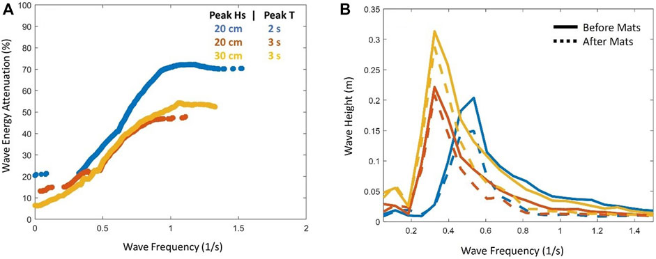
FIGURE 9. (A) Wave frequency (x-axis) versus wave attenuation (y-axis) for the three random cases (colors and legend) centered on varying peak wave heights and peak periods around a JONSWAP spectra with
These lab experiments show the potential for a modular network of floating mats to reduce incident wave energy. We see a strong relationship between the wave steepness and the attenuation, where steeper waves are more attenuated than shallower ones (Figure 7A). We divide this into wavelength and wave height (Figure 7B) to better understand this relationship, and find that wavelength is a primary indicator of wave attenuation. The test conditions with both regular waves and random waves suggest that the geometry of the network relative to the incident wavelength drives wave attenuation. The majority of the wave attenuation occurs at wavelengths shorter than or equal to the length of individual mats, though wave energy continues to be reduced until the wavelengths grow beyond the cross-shore footprint of the entire mat network. Further, the results show that wave attenuation is not appreciably different between sparse and dense network layouts (Figure 7, squares versus circles). Instead, the size of individual mats and the network footprint relative to the wavelength (Figure 7, red dashed lines) have a stronger impact on wave attenuation than the separation between mats.
The mechanics of wave orbital velocity explains some of this dependence. The dissipation of wave velocity in the vertical water column scales with wavelength, with shorter (longer) wavelengths losing energy at shallower (deeper) water depths. A generalization from linear wave theory describes the depth of the wave velocity dissipation as half of the wavelength. The Tutu network is suspended at the surface with a draft of about 0.3 m maximum, thus we would expect the Tutu canopies to impact the shortest waves more than longer waves. To explain the dependence relative to the network footprint (Figure 7B, red dashed lines), we note that if a wave is shorter than the diameter of the Tutu mats then the crest and trough of the wave encounter a mat simultaneously which leads to dissipation. If the wave is longer than an individual mat, but shorter than the network, its crest and trough encounters two or more mats linked together, and energy dissipates owing to tension between them as the wave moves the mats in opposition. If the wave is longer than the entire network, however, the network rides along the wave and dissipation is negligible.
Our initial hypothesis was that the network spacing–sparse and dense–would be a significant factor in wave attenuation, with the denser cluster of mats dampening more wave energy than the sparse cluster. Our results show that there is not a significant difference between the mat spacing in the network for these two configurations, suggesting that the mechanism of mats moving in opposition to dissipate wave energy can work even if that tension is transferred on a rope between them. We cannot generalize to larger spacings between mats than tested here, though we anticipate that at the extreme a Tutu design with too much space between mats will not be in enough tension to dissipate energy. The comparisons between sparse and dense networks, however, do suggest that a field deployment of the Tutu could attenuate waves while allowing space for light to penetrate the water (a concern for ecological systems in the water column and in the benthic region of shallow areas) and space for small craft to move between the network (for maintenance and leisure).
Whether or not the wave energy dissipates at the initial row of mats or after several rows appears to depend on wave height rather than wavelength (Figure 8A). The spatial variance of wave energy within the mat network, calculated using the pressure sensors, shows how much the waves change in the direction of wave propagation. A higher (lower) variance indicates that the wave energy changes within (at the first row of) the network. In this experiment, we found that smaller incident waves had little energy variance within the mat network, suggesting that the first row of mats dissipate the bulk of the energy. Higher energy waves often had more energy variance within the mat network, suggesting that the waves change as they moved through the network. The wavelength does not appear to be as relevant as the wave height in determining where within the network the waves dissipate. Wavelength indicates whether dissipation will happen at all, and wave height directly correlates to the wave velocity (Figure 8B). the amount of energy in a wave, and thus likely the number of mat rows the wave needs to encounter for that energy to attenuate.
The results presented here are relevant for dense floating mats with minimal, short, stiff “emergent vegetation” represented by the rain screen, but not for mats with submerged vegetation. We found that the strips of tulle sewn to the bottom were not influencing the wave attenuation. We tested this by flipping the mats and re-running the Dense network regular waves, which produced similar results. At most 12 bunches of tulle were sewn onto each mat, and the bunches extended down to less than 20% of the water depth, so it is perhaps unsurprising that the effect was small. Observations from cameras placed underwater around the mats showed that the tulle was moving freely with the waves, and thus had little rigidity to contribute to energy attenuation. However, a concurrent full-scale prototype of a Tutu mat deployed in East Boston in summer 2021 showed dense vegetation undergrowth after 2 months in the water, which would have translated to a column of vegetation at least a meter deep in our wave basin experiments. Previous studies with kelp suggest that this type of submerged vegetation will enhance the dissipation of waves. These studies measured and modeled the dissipation of waves by suspended canopies of submerged kelp (fixed to a rigid platform above the water surface) (Zhu et al., 2021; Zhu et al., 2022) and suggest that the wave attenuation would improve with more realistic submerged vegetation structures, possibly extending the wavelengths at which the scaled Tutu is effective.
Our results build on previous work studying wave attenuation by floating individual canopies, notably experiments simulating floating shellfish farms in the field (Zhu et al., 2020). These experiments focused on dense buoys tethered individually to the sea floor and subjected to random wave attack. Attenuation measured from these tests using random waves are similar to Figure 9, with suspended canopies attenuating waves at higher frequencies better than at lower frequencies and plateauing at high frequencies. The plateau evident in Figure 9A occurs at wave frequencies greater than 1 Hz, which for a basin water depth of 1.36 m translates to a wavelength of 1.5m, which is also the diameter of our mats. The plateau appears to occur when the wavelength is at or smaller than the mat diameter. Zhu et al. (2020) further shows that the number of floating elements within the canopy influences attenuation, with more floating elements providing greater attenuation. This suggests that adding more mats to a Tutu network will improve performance at longer wavelengths.
In particular, Zhu et al. (2020) test the potential of combining floating shellfish farms (buoyant elements on individual tethers) with submerged seagrass or other vegetation patches anchored to the seafloor. Their results suggest that the floating farms can attenuate short waves and the submerged vegetation can attenuate longer waves (whose wave orbital velocities are more likely to penetrate the water column to the bed). This supports the idea that a tiered NBS approach to coastal protection should be used to protect against storm waves, with floating elements tackling higher wave frequencies and submerged elements tackling lower wave frequencies. The results presented above suggest that we can extend the frequency range attenuated by floating elements through interconnections between dense mats and network geometry. Future work will investigate how dense, suspended undergrowth from the mats impacts wave attenuation, and will likely expand the range of wave frequencies that a floating structure such as the Emerald Tutu can dissipate.
We tested the efficacy of a new NBS called the Emerald Tutu to attenuate waves in nearshore environments. Physical analogues of the mats were tested in the OH Hinsdale Wave Basin at Oregon State University for both regular and random wave conditions. Results from these tests show that wave attenuation depends on the geometry of the mat system, notably mat size and network size relative to the wavelength. These results are in line with previous work studying wave attenuation in the field owing to individually anchored floating shellfish farms. Both results suggest that floating nearshore networks of mats have the potential to protect the coastline from wave attack. Future research into the Tutu will include testing the impact of submerged vegetation, suspended from the mats, on additional wave attenuation, and developing a non-hydrostatic numerical model to replicate these lab results and scale them to the field.
The datasets presented in this study can be found in online repositories. The names of the repository/repositories and accession number(s) can be found below: https://www.designsafe-ci.org/data/browser/public/designsafe.storage.published/PRJ-3283.
JH, JT, and GC collected data for the experiment. JH and LW processed the data. JH wrote the manuscript, while LW and NL collaborated on revisions.
NSF SBIR Phase 1: funds for the experiment and the prototypes of the Tutu deployed and studied in 2021. This work was funded by a Phase 1 grant from the NSF Small Business Innovation Research (SBIR) program.
The authors declare that the research was conducted in the absence of any commercial or financial relationships that could be construed as a potential conflict of interest.
All claims expressed in this article are solely those of the authors and do not necessarily represent those of their affiliated organizations, or those of the publisher, the editors, and the reviewers. Any product that may be evaluated in this article, or claim that may be made by its manufacturer, is not guaranteed or endorsed by the publisher.
We are forever grateful to the staff of the OH Hinsdale Wave Basin, who were invaluable in helping us to set up the instrumentation around the mat network, troubleshooting wave maker functionality issues, determining the best sets of regular and random waves to prioritize for our time in the facility, and being an amazing crew who fostered an excellent scientific environment. In particular, we would like to thank Pedro Lomonaco and Tim Maddux for being patient with us as we filled the space with wood chips, sewing machines, and colorful playmats. We also thank the REU students who helped us build and monitor the mats, Chelsea Wilhite, Alexis Lipovich, and Carter Howe.
Bergstrom, E., Silva, J., Martins, C., and Horta, P. (2019). Seagrass Can Mitigate Negative Ocean Acidification Effects on Calcifying Algae. Sci. Rep. 9 (1), 1–11. doi:10.1038/s41598-018-35670-3
Bi, R., Zhou, C., Jia, Y., Wang, S., Li, P., Reichwaldt, E. S., et al. (2019). Giving Waterbodies the Treatment They Need: A Critical Review of the Application of Constructed Floating Wetlands. J. Environ. Manag. 238, 484–498. Academic Press. doi:10.1016/j.jenvman.2019.02.064
Chausson, A., Turner, B., Seddon, D., Chabaneix, N., Girardin, C. A. J., Kapos, V., et al. (2020). Mapping the Effectiveness of Nature‐based Solutions for Climate Change Adaptation. Glob. Change Biol. 26 (11), 6134–6155. Blackwell Publishing Ltd. doi:10.1111/gcb.15310
Chen, X., Chen, Q., Zhan, J., and Liu, D. (2016). Numerical Simulations of Wave Propagation over a Vegetated Platform. Coast. Eng. 110, 64–75. Elsevier. doi:10.1016/j.coastaleng.2016.01.003
Crooks, S., Herr, D., Tamelander, J., Laffoley, D., and Vandever, J. (2011). Marine Ecosystem Series Mitigating Climate Change through Restoration and Management of Coastal Wetlands and Near-Shore Marine Ecosystems Challenges and Opportunities. Washington, DC: World Bank. Available at: www.worldbank.org/environment/publications (Accessed December 10, 2020).
de Schipper, M. A., Ludka, B. C., Raubenheimer, B., Luijendijk, A. P., and Schlacher, T. A. (2020). Beach Nourishment Has Complex Implications for the Future of Sandy Shores. Nat. Rev. Earth Environ. 2, 70–84. doi:10.1038/s43017-020-00109-9
Faulwetter, J. L., Burr, M. D., Cunningham, A. B., Stewart, F. M., Camper, A. K., and Stein, O. R. (2011). Floating Treatment Wetlands for Domestic Wastewater Treatment. IWA Publ. 64 (10), 2089–2095. doi:10.2166/wst.2011.576
Howard, J., Sutton-Grier, A., Herr, D., Kleypas, J., Landis, E., Mcleod, E., et al. (2017). Clarifying the Role of Coastal and Marine Systems in Climate Mitigation. Front. Ecol. Environ. 15 (1), 42–50. Wiley Blackwel. doi:10.1002/fee.1451
Hwang, L., and LePage, B. A. (2011). “Floating Islands-An Alternative to Urban Wetlands,” in Wetlands (Dordrecht: Springer Netherlands), 237–250. doi:10.1007/978-94-007-0551-7_14
Isaacson, M. (1991). Measurement of Regular Wave Reflection. J. Waterw. Port, Coast. Ocean Eng. (ASCE) 117 (6), 553–569. doi:10.1061/(asce)0733-950x
Menéndez, P., Losada, I. J., Torres-Ortega, S., Narayan, S., and Beck, M. W. (2020). The Global Flood Protection Benefits of Mangroves. Sci. Rep. 10, 4404. doi:10.1038/s41598-020-61136-6
Morris, R. L., Konlechner, T. M., Ghisalberti, M., and Swearer, S. E. (2018). From Grey to Green: Efficacy of Eco-Engineering Solutions for Nature-Based Coastal Defence. Glob. Change Biol. 24 (5), 1827–1842. Blackwell Publishing Ltd. doi:10.1111/gcb.14063
Quartel, S., Kroon, A., Augustinus, P. G. E. F., Van Santen, P., and Tri, N. H. (2007). Wave Attenuation in Coastal Mangroves in the Red River Delta, Vietnam. J. Asian Earth Sci. 29 (4), 576–584. Pergamon. doi:10.1016/J.JSEAES.2006.05.008
Sarabi, S., Han, Q., Vries, de, and Wendling, L. A. (2019). Key Enablers of and Barriers to the Uptake and Implementation of Nature-Based Solutions in Urban Settings: A Review. Resources 8 (3), 121. doi:10.3390/resources8030121
Smallegan, S. M., Irish, J. L., Van Dongeren, A. R., and Den Bieman, J. P. (2016). Morphological Response of a Sandy Barrier Island with a Buried Seawall during Hurricane Sandy. Coast. Eng. 110, 102–110. Elsevier B.V. doi:10.1016/j.coastaleng.2016.01.005
Stive, M. J. F., de Schipper, M. A., Luijendijk, A. P., Aarninkhof, S. G. J., van Gelder-Maas, C., van Thiel de Vries, J. S. M., et al. (2013). A New Alternative to Saving Our Beaches from Sea-Level Rise: The Sand Engine. J. Coast. Res. 290, 1001–1008. The Coastal Education and Research Foundation. doi:10.2112/JCOASTRES-D-13-00070.1
Sutton-Grier, A. E., Wowk, K., and Bamford, H. (2015). Future of Our Coasts: The Potential for Natural and Hybrid Infrastructure to Enhance the Resilience of Our Coastal Communities, Economies and Ecosystems. Environ. Sci. Policy 51, 137–148. doi:10.1016/j.envsci.2015.04.006
van Duin, M. J. P., Wiersma, N. R., Walstra, D. J. R., van Rijn, L. C., and Stive, M. J. F. (2004). Nourishing the Shoreface: Observations and Hindcasting of the Egmond Case, The Netherlands. Coast. Eng. 51 (8–9). Elsevier, 813–837. doi:10.1016/j.coastaleng.2004.07.011
Zhu, L., Huguenard, K., Fredriksson, D. W., and Lei, J. (2022). Wave Attenuation by Flexible Vegetation (And Suspended Kelp) with Blade Motion: Analytical Solutions. Adv. Water Resour. 162, 104148. Elsevier. doi:10.1016/j.advwatres.2022.104148
Zhu, L., Huguenard, K., Zou, Q.-P., Fredriksson, D. W., and Xie, D. (2020). Aquaculture Farms as Nature-Based Coastal Protection: Random Wave Attenuation by Suspended and Submerged Canopies. Coast. Eng. 160, 103737. Elsevier B.V. doi:10.1016/j.coastaleng.2020.103737
Keywords: coastal resilience, nature-based solutions, vegetated solutions, wave attenuation, floating canopy, climate change
Citation: Hopkins J, Lutsko N, Cira G, Wise L and Tegeler J (2022) The Emerald Tutu: Floating Vegetated Canopies for Coastal Wave Attenuation. Front. Built Environ. 8:885298. doi: 10.3389/fbuil.2022.885298
Received: 27 February 2022; Accepted: 06 May 2022;
Published: 09 June 2022.
Edited by:
Brian C McFall, U.S. Army Engineer Research and Development Center, United StatesReviewed by:
Longhuan Zhu, Michigan Technological University, United StatesCopyright © 2022 Hopkins, Lutsko, Cira, Wise and Tegeler. This is an open-access article distributed under the terms of the Creative Commons Attribution License (CC BY). The use, distribution or reproduction in other forums is permitted, provided the original author(s) and the copyright owner(s) are credited and that the original publication in this journal is cited, in accordance with accepted academic practice. No use, distribution or reproduction is permitted which does not comply with these terms.
*Correspondence: Julia Hopkins, ai5hLmhvcGtpbnNAbm9ydGhlYXN0ZXJuLmVkdQ==
Disclaimer: All claims expressed in this article are solely those of the authors and do not necessarily represent those of their affiliated organizations, or those of the publisher, the editors and the reviewers. Any product that may be evaluated in this article or claim that may be made by its manufacturer is not guaranteed or endorsed by the publisher.
Research integrity at Frontiers
Learn more about the work of our research integrity team to safeguard the quality of each article we publish.