 Jie Hu
 Wei Li
94% of researchers rate our articles as excellent or good
Learn more about the work of our research integrity team to safeguard the quality of each article we publish.
Find out more
ORIGINAL RESEARCH article
Front. Built Environ., 21 June 2022
Sec. Fire Resistant Engineering
Volume 8 - 2022 | https://doi.org/10.3389/fbuil.2022.883454
This article is part of the Research TopicInsights in Fire Resistant Engineering: 2021View all 4 articles
Concrete-filled steel tubular (CFST) structures using high-strength materials have been increasingly used in civil engineering due to their exceptional mechanical performance. A comprehensive numerical analysis was performed in this study, where a finite element model was established for a CFST stub column using high-strength materials with consideration of fire and load combinations. The influence of critical parameters to the resistance in axial compression were analyzed based on the verified model, including the fire exposure time, the axial load level, the confinement factor, etc. The results showed that the residual resistance of a high-strength circular CFST (HCFST) column in axial compression decreased with the increase of axial load level and fire exposure time, while it increased with the increase of material strength.
The circular concrete-filled steel tubular (CFST) has been widely used in engineering structures for its high compressive capacity, exceptional seismic performance, and convenient constructability. Using high-strength steel (fy≥460 MPa) and high-strength concrete (fcu≥60 MPa) in CFST can further improve the structural compressive capacity and save the amount of materials and the cost. Therefore, CFST structures using high-strength materials have been increasingly used in civil engineering projects such as high-rise buildings (Han, 2016). On the other hand, fire occurs frequently in modern society. The performance of damaged structures after fire has been gravely scrutinised. It is of great scientific significance and engineering application value to study the compressive capacity of high-strength concrete-filled steel tubular structures after fire.
In the past, the mechanical properties of CFST structures with high strength concrete at room temperature have been studied extensively, and calculation methods of the compressive capacity of CFST structures at room temperature have been proposed (Liew and Xiong, 2012; Han, 2016). Experimental and theoretical analysis has also been conducted on the fire resistance of CFST structures with normal strength materials. Han and Feng (1995) conducted a fire resistance test of CFST short columns and analyzed the influence of various factors on the fire resistance of CFST columns. Huo and Han (2002) studied the compressive capacity of a CFST cross section after fire and proposed relevant calculation formulas. Xiong and Liew (2015), Xiong and Liew (2016), Han (2016), Han et al. (2017), and Mirmomeni et al. (2017) studied the fire resistance rating and mechanical properties of steel tube high-strength concrete under and after high temperature. Song et al. (2010) established a finite element model and studied the influence of load ratio during fire, fire exposure time, and other parameters on the compressive capacity of CFST short columns using normal materials after fire. Kamil et al. (2019a) and Kamil et al. (2019b) made a fiber element simulation of interaction behaviour of local and global buckling in axially loaded rectangular concrete-filled steel tubular slender columns under fire exposure and made a numerical analysis of axially loaded rectangular concrete-filled steel tubular short columns at elevated temperatures.
However, the research on the mechanical properties of HCFST after fire is still rather limited, which restricts the application of HCFST in practical engineering. In this paper, the research of high-strength steel and high-strength concrete of a concrete-filled steel tubular short column is conducted, and a finite element model on the high strength concrete-filled steel tubular short column under the effect of temperature and load coupling is established. The stress distribution, the effect of fire and load combination, and the residual loading capacity of the high-strength CFST stub column is studied, which will provide a scientific basis for the structural strength assessment after fire exposure.
A finite element model was established in the ABAQUS software platform, while the whole fire process was analysed by the thermal mechanics sequential coupling method. The model consisted of a heat transfer analysis model and a mechanical analysis model.
The heat transfer analysis model is used to calculate the temperature field of the specimen during the fire. The temperature field result of heat transfer analysis is introduced into the stress analysis model, where the deterioration response of materials at high temperature and the compressive capacity of the section after fire was calculated accordingly.
Figure 1 shows the analysis path under the combination of fire and load (Han, 2016), where T represents the temperature, N represents the load, t represents the time, T0 represents the ambient temperature, and N0 represents the load applied at ambient temperature. The typical analysis path is as follows: 1) loading at ambient temperature (AA′): the load increases from 0 to the initial value N0; 2) loading and heating stage (A’B’): the load N0 remains unchanged, the time t increases from 0 to the set time th while the temperature rises from T0 to set temperature Th following the ISO-834 standard fire curve; 3) loading and cooling section (B’C’D’): the load N0 remains unchanged, the temperature drops to T0, and the whole structure continues cooling down to the ambient temperature; and 4) loading after fire (D’E’): the load increases until the structure is damaged under ambient temperature. The path AA’B’C’D’E can reasonably reflect the loading situation of the structure in a real fire.
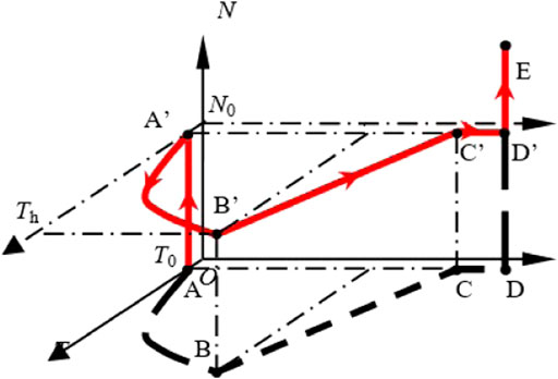
FIGURE 1. Temperature-load-time curve.
For the thermal parameters of steel and concrete, the calculation methods proposed by Lie (1994) were adopted, including the thermal conductivity coefficient, specific heat, and density.
For the mechanical properties, the constitutive relations of steel provided by Lie (1994) were used to calculate the steel at normal temperature and the heating stage, and the double-line model proposed by Yang et al. (2008) was used to calculate the constitutive relation after high temperature. For the concrete, the stress-strain relation at ambient temperature and the heating stage proposed by Han (2016) was adopted. And in the post-fire stage, the temperature correction was made to adjust the peak stress and strain (Song et al., 2010).
In the heat transfer analysis model, the DS4 element was used for the steel tube, the DC3D8 element was used for the concrete and loading plates, and the global size of the grid was approximately 15 mm. For the surface heat exchange condition of the steel tube, the heat dissipation coefficient of the film layer was 25 W/(m2K) and the emissivity of the steel tube surface εm was 0.7. The interface heat transfer between the steel tube and concrete was set according to Ghojel (2004). The “Tie” contact was set between the concrete and upper and lower plates.
In the mechanical analysis model, the S4R shell element was used for the steel tube, and the C3D8R solid element was used for the concrete and loading plates. The mesh was consistent with that in the thermal analysis model to ensure the results imported correctly from the last step. For the contact between the steel tube and concrete, the friction coefficient of tangential behaviour was 0.6, the friction mode was selected as “Penalty”, and the normal behaviour was chosen as “Hard” contact. The “Tie” contact was set between the steel tube, concrete, and upper and lower plates. The load was applied at one end while the other end was fixed. The mesh of the finite element model is shown in Figure 2.
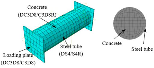
FIGURE 2. Mesh of the finite element model.
The axial compression performance of high-strength CFST at room temperature, the fire resistance rating of CFST, and the compressive performance of the CFST short column after the fire were calculated using the established finite element model, and compared with the existing test results.
Figure 3A shows the measured and predicted load-displacement curves of the high-strength CFST stub column under axial compression at ambient temperature (Specimen S1-three to three in Liew et al., 2016). Figure 3B shows the comparison results of the displacement time-history of the CFST column end (Specimen C1-1 in Han, 2016). Figure 3C shows the calculation and test comparison results of the load-strain curve of CFST short columns under compression after fire exposure (Specimen CF-1 in Song et al., 2010), while the load is kept constant during the fire. It can be seen that the predicted results were in good agreement with the experimental ones in terms of the compressive stiffness and compressive capacity of the CFST stub column using high-strength materials at ambient temperature, the fire resistance rating of normal CFST, and the compressive capacity of the CFST section after fire.
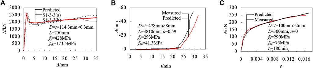
FIGURE 3. Verification results. (A) Axial compressive performance at ambient temperature. (B) Fire resistence. (C) Axial compressive performance after fire.
The finite element model was used to further analyse the compressive behaviour of high-strength CFST short columns after fire. The basic information of the numerical prototype is as follows: steel tube profile is D×t = 600 mm × 12 mm, column length L = 1800 mm (D:L = 1:3); the compressive strength of the high-strength concrete cube fcu = 80 MPa, the yield strength of the high-strength steel tube fy = 460 MPa; axial load level (defined as the ratio of initial load to ultimate compressive capacity at ambient temperature) n = 0.2; fire exposure time is 1 h.
Temperature curves of points in the middle section of high-strength CFST specimens are shown in Figure 4. Among them, point 1 is the temperature measuring point of the outer surface of the steel tube, and points 2, 3, 4, and 5 are the temperature measuring points in the radial direction at the concrete section a total of 0, 96, 192, and 288 mm away from the outer surface of concrete, respectively.
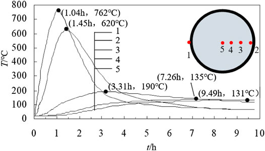
FIGURE 4. T-t curve of middle section of high strength CFST.
It can be seen that the historical maximum temperature experienced by the section decreases successively from the outside to the inside. Due to the thermal resistance between the steel tube and concrete and the low thermal conductivity of concrete, the temperature change of concrete has a certain delay, and the concrete centre has the lowest historical maximum temperature.
The axial load (N)- axial displacement (Δ) curve of a typical calculation example is shown in Figure 5. It can be seen that the curve of this numerical sample can be divided into four stages: 1) loading at ambient temperature (oa): the column develops axial compression deformation; 2) at the beginning of the loading-heating stage (aa’): when the column load is small, the compressive deformation is smaller than the expansion caused by thermal expansion, and the specimen has expansion deformation; 3) loading-heating and loading-cooling stage (a’b): when the temperature continues to rise, the compressive displacement exceeds the expansion due to the increasing degree of material deterioration, and the specimen begins to develop compressive deformation; when the ambient temperature starts to cool, the axial shortening of the column is further increased due to the continuous temperature increase inside the section and the deterioration of concrete material performance; and 4) post-fire loading stage (bc): with the increase of axial compressive deformation, the load increases to the peak value and then decreases.
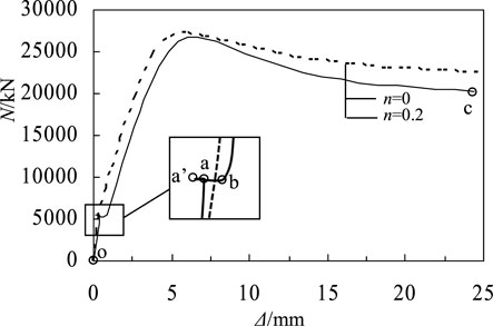
FIGURE 5. N-Δ curve of specimen section.
In Figure 5, the N-Δ curve of the specimen without loading during fire is also presented, which follows the analysis path ABCDE in Figure 1. It can be seen that the post-fire compressive capacity of the section without load during fire was about 5% higher than that with constant load (n = 0.2) during fire. This was because the internal force redistribution occurred in the column during the whole process of fire, which affected the structural behaviour after fire.
The proportion of axial load carried by the steel tube and core concrete in the post-fire loading stage is shown in Figure 6. In the initial loading stage, due to the residual stress and deformation generated in the heating and cooling stage, the steel tube bears approximately 40% of the load. With the increase of deformation, the proportion of axial load resisted by the steel tube decreased to the extreme point and then increased gradually.
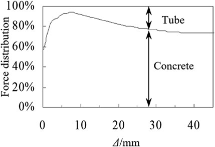
FIGURE 6. Axial force distribution.
Figure 7 shows the contact stress variation between the steel tube and concrete at different stages.
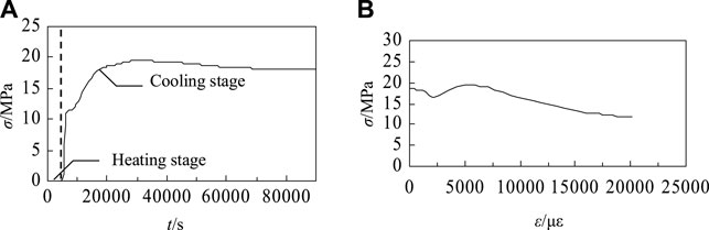
FIGURE 7. Change of contact stress between steel tube and concrete. (A) Heating and cooling stage. (B) Post-fire loading stage.
In the loading-heating stage, there was no contact stress between the steel tube and concrete, as the thermal expansion of the steel tube is much larger than that of the concrete. In the loading-cooling stage, the steel tube shrinks rapidly while the internal concrete is still being heated and expanding. The steel tube is in contact with concrete, and the maximum contact stress is 19.4 MPa. With the decrease of temperature, the concrete also begins to shrink gradually, and the contact stress decreases accordingly.
At the beginning of post-fire loading stage, the initial contact stress starts to decrease as the transverse deformation of the steel tube grows. It begins to increase as the plastic deformation develops in the concrete. The contact stress between the concrete and steel tube increases gradually with a maximum value of approximately 20 MPa. The contact stress decreases again with the deterioration of concrete with a minimum value of approximately 10 MPa, which ensures the confinement effect of high-strength steel tube to the high-strength concrete.
Based on the verified finite element model, the influence of the key parameters on the post-fire compressive strength of the high-strength CFST stub column is analysed. The geometry of the basic specimen is the same as that in Compressive Performance of Stub Column After Fire. The main parameters include: fire exposure time (0–180 min), diameter-thickness ratio (defined as D/t, where D and t represent the outer diameter and the thickness of the steel tube, respectively), axial load level (0∼0.3), the compressive strength of concrete (80∼120 MPa), and the yield strength of the steel tube (460∼690 MPa).
Figure 8 shows the load-displacement (N-Δ) curves of each specimen after fire when n = 0.2, where the specimens are subjected to fire for 0, 90, and 180 min. It can be seen from the figure that, under the same other conditions, the post-fire compression capacity of high-strength CFST specimens decreased with the increase of fire exposure time. The specimens subjected to fire for 90 and 180 min reduced by 13 and 24% respectively when compared with those without fire exposure.
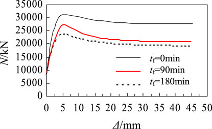
FIGURE 8. The influence of fire time on N-Δ curve.
Figure 9 shows the post-fire load-displacement curves of specimens with diameter to thickness ratios of 75, 60, 50, and 43 when the axial load level is 0.2 and the fire exposure time is 90 min. It can be seen that when other conditions were the same, the post-fire compressive strength of the high-strength CFST section increased with the decrease of the diameter to thickness ratio. For example, when the D/t reduced from 75 to 43, the post-fire compression capacity of the section increased by 23%. This was because the smaller the diameter to thickness ratio, the stronger the confinement effect of the high-strength steel tube provided, and the improvement of concrete strength was more significant.
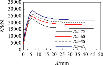
FIGURE 9. The influence of D/t on N-Δ curve.
Load-displacement curves of specimens with axial compression levels of 0, 0.1, 0.2, and 0.3 after the same fire exposure time are shown in Figure 10. It can be seen that when the fire exposure time was 90 min, the influence of axial compression level on the residual compressive capacity of the specimen section is not significant. The cross-sectional compressive capacity with an axial load level of 0.3 decreased by less than 5% compared with that without constant axial load. When subjected to fire for 180 min, the compressive capacity of specimens with an axial load level of 0.3 was about 10% lower than that without axial load. During the fire, the internal force redistribution occurred in the specimen, which might affect the ultimate compressive capacity after fire. The effect increased when the fire exposure time was longer.
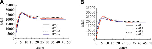
FIGURE 10. The influence of n on N-Δ curve. (A) tf = 90 min (B) tf = 180 min.
Figure 11 shows load-displacement curves of specimens with tube yield strengths of 460, 550, and 690 MPa. It can be seen that the post-fire compression capacity of the high-strength CFST short column increased with the increase of the yield strength of the steel tube. When the yield strength of the steel tube increased from 460 to 690 MPa, the cross-sectional compressive strength after fire increased by 25%.
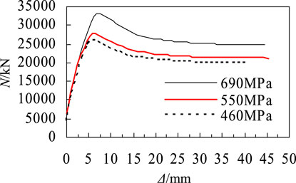
FIGURE 11. The influence of fy on the N-Δ curve.
Figure 12 shows load-displacement curves of specimens with concrete strength grades of C80, C100, and C120. It can be seen that the compressive strength of high-strength CFST short columns after fire increased with the increase of the compressive strength of concrete. When the concrete strength grade increased from C80 to C120, the compressive capacity increased by 28%.

FIGURE 12. The influence of fcu on the N-Δ curve.
In this paper, finite element analysis was carried out on the compressive performance of high-strength CFST stub columns after fire. The following conclusions were obtained within the parameters of this paper.
1) The results of the established comprehensive numerical model were in good agreement with the test results in terms of fire resistance rating and cross-sectional compressive strength before and after fire of CFST columns.
2) Using high strength materials could significantly improve the post-fire compressive capacity of specimens. For instance, when the yield strength of the steel tube increased from 460 to 690 MPa, the cross-sectional compressive strength after fire increased by 25%. When the concrete strength grade increased from C80 to C120, the compressive capacity increased by 28%.
3) In the post-fire loading stage, the high-strength steel tube still provided effective confinement to the core high-strength concrete. The compressive capacity of the section after fire decreased with the increase of axial load level, fire exposure time, and diameter to thickness ratio.
The original contributions presented in the study are included in the article/Supplementary Material, further inquiries can be directed to the corresponding author.
JH drafted the manuscript and conducted the analysis. WL contributed to the concept, methodology, supervision, and revised the manuscript.
The authors declare that the research was conducted in the absence of any commercial or financial relationships that could be construed as a potential conflict of interest.
All claims expressed in this article are solely those of the authors and do not necessarily represent those of their affiliated organizations, or those of the publisher, the editors and the reviewers. Any product that may be evaluated in this article, or claim that may be made by its manufacturer, is not guaranteed or endorsed by the publisher.
Ghojel, J. (2004). Experimental and Analytical Technique for Estimating Interface thermal Conductance in Composite Structural Elements under Simulated Fire Conditions. Exp. Therm. Fluid Sci. 28 (4), 347–354. doi:10.1016/s0894-1777(03)00113-4
Han, L. H. (2016). Concrete Filled Steel Tubular Structures––Theory and Practice. Third Edition. Peking: Science Press. (in Chinese).
Han, L. H., and Feng, J. B. (1995). The Constitutive Relationship Model of concrete and its Application in the Numerical Analysis of concrete-filled Steel Tube. J. Harbin Univ. Architecture Eng. 5, 26–32. (in Chinese).
Han, L. H., Song, T. Y., and Zhou, K. (2017). Fire Safety Design Theory of Steel-Concrete Composite Structures. Second Edition. Peking: Science Press. (in Chinese).
Huo, J. S., and Han, L. H. (2002). Axial and Flexural Stiffness of concrete-filled Steel Tube after Exposure to ISO-834standard Fire. Earthquake Eng. Eng. Vibration 5, 143–151. doi:10.13197/j.eeev.2002.05.026
Kamil, G. M., Liang, Q. Q., and Hadi, M. N. S. (2019a). Fiber Element Simulation of Interaction Behavior of Local and Global Buckling in Axially Loaded Rectangular concrete-filled Steel Tubular Slender Columns under Fire Exposure. Thin-Walled Structures 145, 106403. doi:10.1016/j.tws.2019.106403
Kamil, G. M., Liang, Q. Q., and Hadi, M. N. S. (2019b). Numerical Analysis of Axially Loaded Rectangular concrete-filled Steel Tubular Short Columns at Elevated Temperatures. Eng. Structures 180, 89–102. doi:10.1016/j.engstruct.2018.11.037
Lie, T. T. (1994). Fire Resistance of Circular Steel Columns Filled with Bar‐Reinforced Concrete. J. Struct. Eng. 120 (5), 1489–1509. doi:10.1061/(asce)0733-9445(1994)120:5(1489)
Liew, J. Y. R., and Xiong, D. X. (2012). Ultra-high Strength concrete Filled Composite Columns for Multi-Storey Building Construction. Adv. Struct. Eng. 15 (9), 1487–1503. doi:10.1260/1369-4332.15.9.1487
Liew, J. Y. R., Xiong, M., and Xiong, D. (2016). Design of Concrete Filled Tubular Beam-Columns with High Strength Steel and Concrete. Structures 8 (2), 213–226. doi:10.1016/j.istruc.2016.05.005
Mirmomeni, M., Heidarpour, A., Zhao, X.-L., and Packer, J. A. (2017). Effect of Elevated Temperature on the Mechanical Properties of High-Strain-Rate-Induced Partially Damaged concrete and CFSTs. Int. J. Impact Eng. 110, 346–358. doi:10.1016/j.ijimpeng.2017.02.006
Song, T.-Y., Han, L.-H., and Uy, B. (2010). Performance of CFST Column to Steel Beam Joints Subjected to Simulated Fire Including the Cooling Phase. J. Constructional Steel Res. 66 (4), 591–604. doi:10.1016/j.jcsr.2009.12.006
Xiong, M.-X., and Liew, J. Y. R. (2016). Mechanical Behaviour of Ultra-high Strength concrete at Elevated Temperatures and Fire Resistance of Ultra-high Strength concrete Filled Steel Tubes. Mater. Des. 104, 414–427. doi:10.1016/j.matdes.2016.05.050
Xiong, M.-X., and Richard Liew, J. Y. (2015). Spalling Behavior and Residual Resistance of Fibre Reinforced Ultra-high Performance concrete after Exposure to High Temperatures. Mater. Construcc. 65 (320), e071. doi:10.3989/mc.2015.00715
Keywords: high-strength concrete-filled steel tube, stub column, post-fire, resistance in axial compression, numerical analysis
Citation: Hu J and Li W (2022) Numerical Analysis on Post-Fire Resistance of High-Strength Circular CFST Stub Column in Axial Compression. Front. Built Environ. 8:883454. doi: 10.3389/fbuil.2022.883454
Received: 25 February 2022; Accepted: 04 April 2022;
Published: 21 June 2022.
Edited by:
Amin Heidarpour, Monash University, AustraliaCopyright © 2022 Hu and Li. This is an open-access article distributed under the terms of the Creative Commons Attribution License (CC BY). The use, distribution or reproduction in other forums is permitted, provided the original author(s) and the copyright owner(s) are credited and that the original publication in this journal is cited, in accordance with accepted academic practice. No use, distribution or reproduction is permitted which does not comply with these terms.
*Correspondence: Wei Li, aWxpd2VpQHRzaW5naHVhLmVkdS5jbg==
Disclaimer: All claims expressed in this article are solely those of the authors and do not necessarily represent those of their affiliated organizations, or those of the publisher, the editors and the reviewers. Any product that may be evaluated in this article or claim that may be made by its manufacturer is not guaranteed or endorsed by the publisher.
Research integrity at Frontiers
Learn more about the work of our research integrity team to safeguard the quality of each article we publish.