 Tao Fu
 Kai Wang1
95% of researchers rate our articles as excellent or good
Learn more about the work of our research integrity team to safeguard the quality of each article we publish.
Find out more
ORIGINAL RESEARCH article
Front. Built Environ. , 27 April 2022
Sec. Geotechnical Engineering
Volume 8 - 2022 | https://doi.org/10.3389/fbuil.2022.868908
During the construction of a bridge, due to the deep sand mining in the riverbed at the bridge site, a sand mining disturbance stratum is formed at the bridge site, and it has an impact on the construction quality of the pile group foundation. In this paper, in view of the special geological conditions caused by sand mining, the high-pressure jet grouting method was used to reinforce the disturbed stratum at the bridge site, and a scheme and key construction technology high-pressure rotary jet pile grouting to reinforce the disturbed stratum caused by sand mining is proposed. A three-dimensional finite element model of the pile group before and after reinforcement of the disturbed stratum by high-pressure jet grouting method is established. The distribution characteristics of the lateral displacement of the borehole wall in the disturbed stratum before and after reinforcement are compared and analysed. Application on an actual bridge proves that the high-pressure jet grouting method has a good reinforcement effect on the disturbed stratum, which effectively solves the phenomenon of hole expansion and pile casing falling in the construction process of the pile foundation caused by sand mining disturbance and improves the working performance and construction quality of the pile group foundation. The high-pressure jet grouting technique for reinforcement of disturbed stratum is proved to be effective in practice.
The reinforcement mechanism of the high-pressure rotary jet grouting method is to use high-pressure cement slurry and air sprayed by the duct to jointly impact and destroy the structure of the soil, and fully mix with it to form a cylindrical solid structure with certain strength, so as to strengthen the foundation (Zhu et al., 2015; Liu and Zhao, 2016; Jia N. et al., 2018).
The jet grouting method uses a slurry pump and a high-pressure water pump to change the jet fluid medium for anti-seepage or waterproof curtains. Because the swing angle of the nozzle can be adjusted according to need, the solidified body formed by spraying will be fan-shaped or wall-shaped in an underground anti-seepage project. After fan-shaped or wall-shaped consolidated bodies are superimposed to form a closed area, groundwater infiltration can be effectively prevented, improving the flow properties of the foundation soil and facilitating slope engineering (Shen et al., 2013; Cheng, 2014; Ng and Tan, 2014; LIU et al., 2017).
Wong I H (Wong and Poh, 2020) used rotary jet grouting technology to reinforce a pit wall and bottom, and it was found that it could effectively reduce the uplift of the pit bottom soil and the displacement of the pit wall during excavation. Shibazaki M (Shibazaki, 2003) and Kauschinger J L (Kauschinger et al., 2011) studied the pile forming radius when jet grouting was carried out and an empirical formula for calculating the pile forming radius was obtained. Rollins K M (Rollins et al., 2009) studied the use of high-pressure jet grouting to improve the lateral resistance of a pile group foundation in soft soil and found that jet grouting can significantly improve the lateral resistance of a pile group. Liu Li (Liu and Cui, 2011) studied the mechanism of high-pressure jet grouting strengthening of a pile foundation and found that it could form a composite foundation with the soil between piles, improving bearing capacity and reducing settlement. Ren (2017) studied the advanced support technology and construction process of horizontal high pressure jet grouting, and analyzed the reinforcement effect of horizontal high pressure jet grouting technology. The results show that the advanced reinforcement of horizontal high pressure jet grouting has good effect on reducing settlement and deformation in soft strata, and can meet the requirements of safe construction. Jia J. et al. (2018) studied the bearing capacity of high-pressure jet grouting pile composite foundation based on the subgrade of a railway hub southwest ring railway. According to the numerical simulation calculation, the characteristic value of composite foundation bearing capacity was obtained, which can be used for construction reference. Han and Wang (2019) took the air jet pressure during the rotary jet grouting construction as the main control parameter, and proposed a quantitative calculation formula that could express the effect of compressed air on the increase of pile diameter through regression analysis, which significantly increased the pile diameter of high-pressure rotary jet grouting pile and improved the reinforcement effect of rotary jet grouting method on soft soil foundation. Liu (2019) analyzed the calculation of bearing capacity of composite foundation and its mechanical characteristics under vertical load, and proposed a calculation model of bearing capacity of high-pressure jet grouting pile composite foundation for construction reference. Zhang and Wang (2020) proposed the concept of high-pressure jet grouting pile reinforcement of bridge deep foundation pit combined with aeolian sand characteristics, provided technical support for the construction of bridge deep foundation pit. Shangzhi (2021) established the research and application framework of strengthening karst cavity soft foundation with high-pressure jet grouting pile. The results show that the integrity, stability and continuity of the foundation are significantly improved after high pressure jet grouting pile reinforcement.
During the construction of the bridge, the riverbank in the construction area of the main bridge site collapsed. After preliminary measurement, there was a significant deviation between the riverbed elevation and the design map, and riverbed subsidence was diagnosed. According to the analysis, the riverbed and riverbank collapse around the bridge site were caused by sand mining, as shown in Figure 1. The soil above the sand mining layer was in a state of settlement, which made the riverbed soil loose, forming disturbed strata. Through measurement, it was found that the riverbed had collapsed by between 7 and 8 m due to the serious sand mining at the location of the main bridge, and the influence range of the soil layer was deep. After geological investigation, it was finally determined that the disturbed strata range was between −18.1 m and −32.8 m, and the disturbance depth of the soil layer reached 14.7 m. The range of soil disturbed by sand mining is shown in Figure 2. In view of the problems of riverbed decline and stratum disturbance, it was necessary to resurvey and check the main bridge. After a core drilling survey and calculations, the original bridge design scheme was changed. A design scheme increasing pile diameter, pile foundation spacing and pile length was adopted. The pile diameter was changed from 2.0 to 2.5 m, and the pile foundation spacing was increased from 5.0 to 6.25 m. After changing the design scheme, the cross-section form of the main pier bearing platform was rectangular, the plane size increased, the thickness increased from 5.0 to 6.0 m, and 20 friction bored piles with a 2.5 m diameter and a 103 m length were set under the pile cap. A schematic diagram of the pile group foundation is shown in Figure 3.
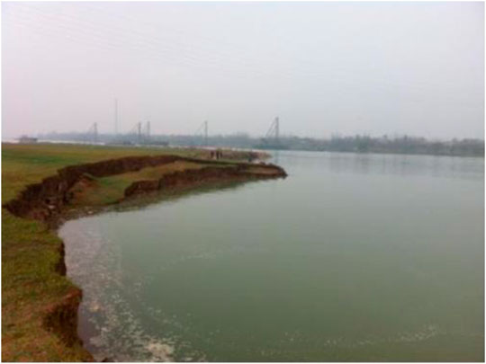
FIGURE 1. Riverbank collapse at bridge site.
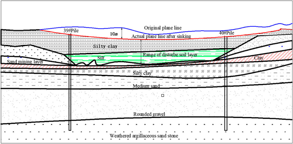
FIGURE 2. Schematic diagram of the range of soil disturbance.
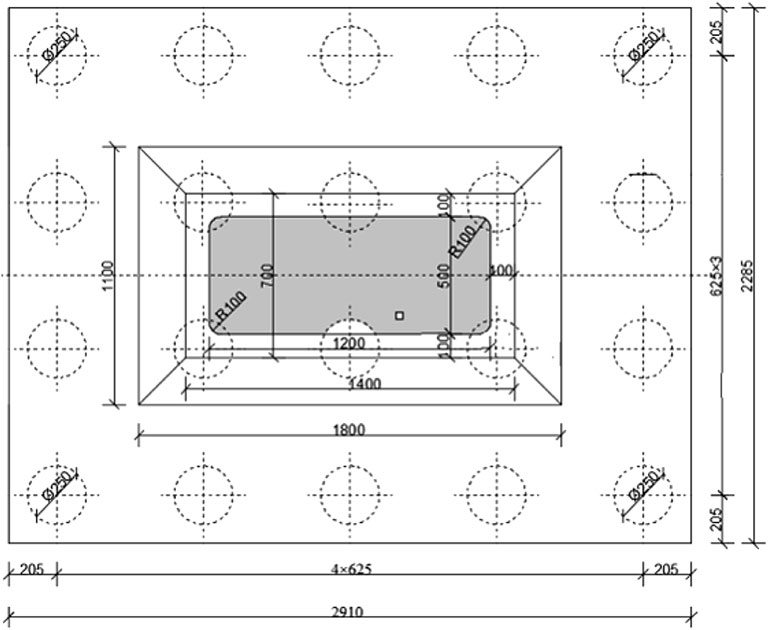
FIGURE 3. Schematic diagram of the pile group fourdation.
In order to control the construction quality of the pile foundation, it was necessary to control the performance index of the mud, and different strata needed to deploy different indexes of mud. Especially for strata disturbed by sand mining, the specific gravity of the wall protection slurry can be increased to achieve better wall protection. Reasonable control of drilling speed, with different drilling speeds for different soil strata is necessary. When drilling into strongly weathered sandy mudstone, due to the high soil viscosity, the phenomenon of “paste backfill” often occurs. The drill bit needed to be lifted and cleaned, resulting in slow drilling. Even if measures to ensure the quality of the pile foundation were adopted in the drilling process, the phenomenon of a sudden sinking of the pile casing and instantaneous failure to enter the water still occurred.
It can be seen that even with slow drilling and high-quality mud wall protection, the phenomenon of hole expansion and pile casing falling still occurred during the drilling process. Furthermore, the deep disturbance range of the stratum, large hole expansion range and deep dropping of the steel casing seriously affected the construction of the pile foundation. It was found that the bottom of the steel casing was located in the range of the disturbed stratum during drilling, and bottom hole reaming developed upward along the outside of the pile casing after it occurred, causing the pile casing to separate from the outside soil. When the friction resistance of the outer soil on the pile casing was not enough to balance with the self-weight of the casing, the casing would fall. Due to the relatively thick disturbed strata and a large range of expansion holes, the falling depth of the pile casing was large.
Analysis of the problems encountered during the drilling of bored piles revealed that, due to the special geological conditions caused by sand mining at the main bridge location, the construction of the bridge group pile foundations was not possible without pre-reinforcement of the disturbed soil layers.
In view of the special geological condition of stratum disturbance caused by sand mining at the main bridge site, the treatment scheme for high-pressure jet grouting reinforcement was adopted. A certain number of high-pressure jet-grouted columns were set around each single pile, and the soil structure was destroyed by the injection of high-pressure mud and air, and a cylindrical consolidation body was formed in the soil to reinforce the disturbed soil layer. Before drilling the cast-in-place pile, a high-pressure jet-grouted column was installed at each bored pile. Thirteen high-pressure jet-grouted columns were set around each foundation pile. The diameter of the jet-grouted columns was 1 m, spaced at 76.57 cm, and the overlap between the jet-grouted columns was 23.34 cm. Three high-pressure jet-grouted columns were set in each foundation pile. The diameter of the jet-grouted columns was 0.8 m, and the pile centre distance was 121.24 cm. The design is shown in Figures 4, 5. There were 16 high-pressure jet-grouted columns applied at each foundation pile position, and a total of 20 foundation piles were under each main pier, meaning 320 high-pressure jet-grouted columns were under each main pier. The upper end of the jet-grouted column is wrapped with a pile casing of 5.0 m, and the lower end is embedded with fully weathered sandy mudstone of 2.0 m.
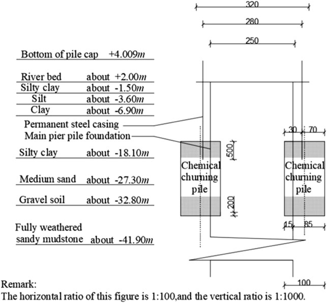
FIGURE 4. Longitudinal section of a high-pressure jet grouted column/cm.
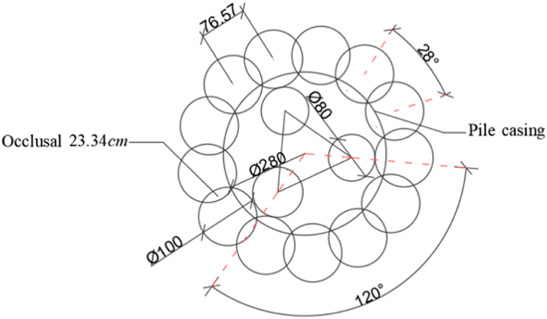
FIGURE 5. Cross-section of a high pressure jet grouted column/cm.
Two finite element models were established by selecting the hole wall after the disturbance stratum was reinforced by high-pressure jet-grouted column as the research object, with an aperture of 2.5 m and a hole depth of 103 m. They were a soil model reinforced by high-pressure jet-grouted columns and a soil model without high-pressure jet-grouted columns. The analytical programme is shown in Table 1.
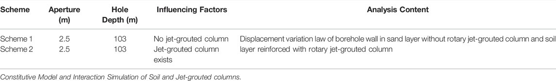
TABLE 1. Stability analysis scheme of hole wall.
Selection of the soil calculation area will directly affect the calculation accuracy of the model. In general, the larger the soil calculation area, the longer the calculation time and the greater the calculation accuracy. Furthermore, the shear strain decreases to zero at the n-times aperture (n is usually 8–15) of the pile shaft from the pile shaft axis. In this paper, when determining the calculation area of the model, 15 times of the aperture was selected as the radius of the lateral boundary of the calculation area. When determining the vertical boundary of the geometric model, the calculation range of twice the length of the pile was taken, that is, a large size was used to establish the model to simulate the semi-infinite space (Liu, 1990). A schematic diagram of the calculation model is shown in Figure 6. The established three-dimensional finite element model is shown in Figure 7.
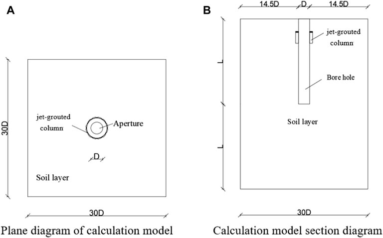
FIGURE 6. Calculation model diagrams. (A) Plane diagram of calculation model. (B) Calculation model section diagram.
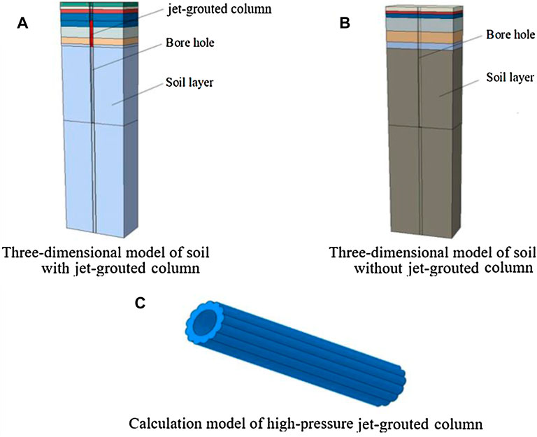
FIGURE 7. Three dimensional fnite element model. (A) Three dimensional model of soil with jet-grouted column. (B) Three-dimensional model of soil without jet-grouted. (C) Calculation model of hige-pressure jet-grouted column.
When establishing the finite element model of the rotary jet-grouted column and the soil layer, the C3D8 element was used. The soil material adopted the Mohr-Coulomb model, which can easily define material parameters of different soils.
Solving the contact between high-pressure rotary piles and soil using penalty functions when simulating a pile-soil model for group pile foundations used the finite element software ABAQUS. In this paper, the normal action of the contact surface was determined by the hard contact method, and the tangential action between surface and surface was determined by the coulomb friction model. By defining the friction coefficient between the contact surfaces, the friction characteristics between the contact interfaces were simulated. When the equivalent friction force was not greater than the critical stress, there would be no slippage (Chandra et al., 2005; Nie, 2016). The determination of the contact surface and the constitutive model of the contact surface are the two main problems to be solved when simulating the contact problem between jet-grouted columns and soil (Wang et al., 2011; Zhang, 2016). When defining the contact model, the Master-Slave contact model was adopted. When determining the master-slave surface, the principle should be based on using the surface with large stiffness as the master surface and the surface with small stiffness as the subordinate surface. If the stiffness of the two surfaces was similar, the coarser grid division was selected as the main control surface. Based on this principle, the surface of the jet grouted pile was selected as the main control surface, and the soil surface was the subordinate surface. When analysing the contact between the jet grouted pile and the soil layer, Coulomb friction was selected, and the friction coefficient between pile and soil was 0.45.
Meshing is the key to numerical simulation. The sweeping technique was used to divide the grid. When dividing the grid, two seeds were divided in the radial direction of the jet-grouted column, and the global seeds were arranged vertically with a density of 0.5. The soil was divided radially at a distance of 2/2.5 (the further away from the axis, the sparser the grid). The global seeds were arranged vertically at a density of 2. The horizontal degree of freedom on the right side of the model was defined as 0, and the horizontal and vertical degrees of freedom at the bottom were defined as 0. Meshing of 2D borehole finite element simulation is shown in Figure 8.
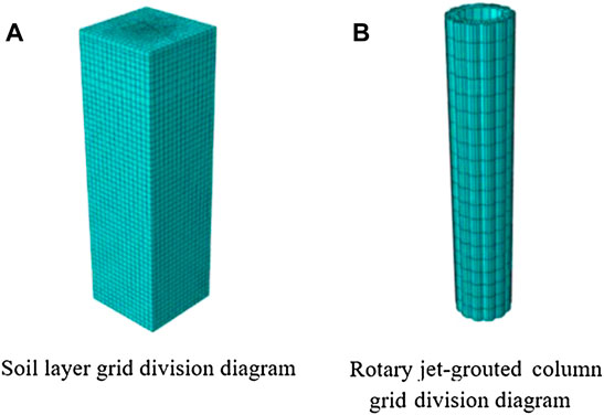
FIGURE 8. Grid division schematics. (A) Soil layar grid division diagram. (B) Rotary jet grouted column grid division diagram.
Soil parameters were selected according to the geological exploration report. Parameter values are selected according to Table 2, jet grouted pile parameters are selected according to Table 3, and mud parameters are selected according to Table 4.
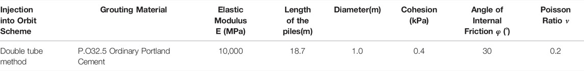
TABLE 2. Calculation parameters of high-pressure jet-grouted column.
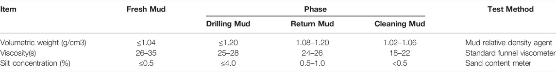
TABLE 3. Mud performance parameters.
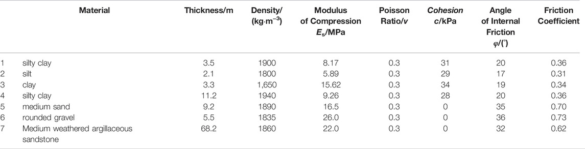
TABLE 4. Calculation parameter table of the soil layer.
Before any construction, although there is no displacement on the surface, there is stress in the soil layer, and the state of stress without displacement is called the ground stress balance (Wang and Liu, 2012; Hu et al., 2018). Firstly, the equilibrium load analysis step of geostress was established, that was, pressing boundary conditions to the finite element model according to the actual situation of the project. Considering the self-weight of the soil, the stress distribution of the soil element under gravity load was calculated, and then the self-weight was applied by defining the equilibrium load step. The internal force of the calculated element was extracted and applied to the finite element model in reverse. According to the balance principle, gravity load was applied to balance the internal force and external force, and the vertical displacement of the surface and the deformation of the soil tended to zero displacement. The initial stress field was defined by inputting the highest and lowest point gravity stresses of different materials and the corresponding coordinates in the initial analysis step. A cloud picture of the vertical displacement of the soil layer after equilibrium is shown in Figure 9. The order of magnitude of the maximum stratum displacement is 10−6 m. The equilibrium results meet the requirements and will not affect the subsequent numerical analysis results.
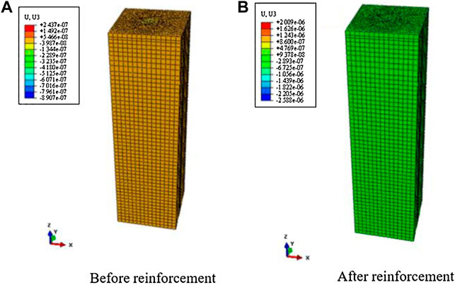
FIGURE 9. Displacement nephogram fter geostress balance/m. (A) Before reinforcement by jet-grouted column. (B) After reinforcement by jet-grouted column.
By defining the Remove analysis step, the soil within the scope of the borehole was removed, and excavation of the borehole was simulated. When the soil was removed, the contact pair between the excavated soil and the undisturbed soil was invalid. The load analysis step was used to impose linear load on the borehole wall to simulate slurry wall protection.
In this paper, the lateral displacement of the borehole wall is analysed for the stability of the borehole wall, and the variation characteristics of lateral displacement of the borehole wall before and after reinforcement of the high-pressure jet-grouted column are compared and analysed, as shown in Figure 10.
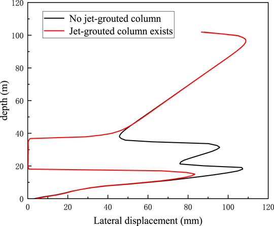
FIGURE 10. Comparison of lateral displacement of hole wall before and after reinforcement by high-pressure jet-grouted column.
It can be seen from Figure 10 that the lateral displacement of the hole wall changed significantly in the range of the jet-grouted column after reinforcement. It was not easy to compress due to the large modulus of the jet-grouted column, so its lateral displacement was very small. On both sides of the jet-grouted column, the change trend of lateral displacement was basically the same. It showed that after the reinforcement by rotary jet-grouted column, the lateral displacement of the hole wall in the soft soil could be effectively reduced, and the stability of the hole wall of the bored pile could be improved to avoid drilling reaming in the drilling process.
The cement used in the grouting material of the high-pressure jet-grouted columns was Ordinary Portland Cement. The strength grade was 42.5, the water cement ratio was controlled to between 0.8 and 1.1, and the slurry temperature was controlled to between 5 and 40°C.
The grouting pressure was controlled to between 20 and 25MPa, the grouting rate was controlled to between 55 and 65 L/min, the lifting speed of the spray rod was controlled to between 13 and 18 cm/min, and the spray speed of the spray rod was controlled to between 18 and 22R/min.
In order to preliminarily understand the reinforcement effect of the high-pressure rotary jet-grouted column on the soil layer, a pile construction test was carried out on the bank beach in the bridge location area. Through observation of the soil layer after excavation, it was found that the reinforcement effect was good.
The high-pressure jet-grouted column was constructed by the double pipe method. In order to prevent the string hole in the construction process, interval drilling was adopted as the construction method for each unit. When crossing the high-compression soil layer, the spraying pressure was appropriately reduced, and the lifting speed and rotation speed were increased.
Construction of the high-pressure jet-grouted columns was divided into three rounds. The peripheral foundation piles were constructed in the first round. After meeting the requirements, the peripheral residual pile foundation was constructed in the second round. The pile foundation in the hole was constructed in the last round. The construction sequence is shown in Figure 11.
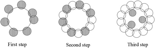
FIGURE 11. Construction secquence.
When a new hole was drilled during the construction of the jet-grouted column, the strength of the hole previously drilled had to meet the requirements. The next round could only be constructed after the high-pressure jet-grouted column reached the age of 2 days.
In the construction process of the high-pressure jet-grouted column, strictly in accordance with the design lofting, the casing was set in the water as a positioning hole. The casing was made of steel pipes with a diameter of 20 cm and a wall thickness of 8 mm. Casing buried depth was no less than 2 m, orifice plane error was not more than 2 cm, casing inclination was not more than 1%, and the orifice was fixed onto the construction platform after accurate positioning. During the drilling process, the verticality of the drilling hole was no more than 1%, and the wall was protected by bentonite slurry.
In this paper, the high-pressure jet grouting method was used to reinforce the disturbed strata due to deep sand mining in view of the phenomenon of hole expansion and pile casing falling during pile foundation drilling. By comparing and analysing the lateral displacement distribution characteristics of the borehole wall in the disturbed strata before and after reinforcement, it was shown that the treatment scheme of high-pressure jet grouting reinforcement of disturbed strata can effectively solve the phenomenon of hole expansion and pile casing falling during drilling, ensuring construction progress, effectively ensuring the construction quality of the pile group foundation and enhancing the reliability and safety of the bridge superstructure. The treatment scheme of high-pressure jet-grouted column to strengthen disturbed strata has a good effect in preventing borehole collapse and enhancing the stability of the borehole wall. The scheme has been proved feasible.
The original contributions presented in the study are included in the article/Supplementary Material, further inquiries can be directed to the corresponding authors.
FT investigation, funding acquisition. WK writing—original draft, date curation, formal analysis. XR writing—review and editing, resources. ZZ validation, software. WL conceptualization, project administration.
This research has been supported by National Natural Science Funds, Grant No. 51408339, China. Natural Science Funds of Shandong Province, Grant No. ZR2021ME227 and Postgraduate Education Quality Improvement Program Funds of Shandong Province, Grant No. SDYAL19110.
WL was employed by Shandong Hi-Speed Group.
The remaining authors declare that the research was conducted in the absence of any commercial or financial relationships that could be construed as a potential conflict of interest.
All claims expressed in this article are solely those of the authors and do not necessarily represent those of their affiliated organizations, or those of the publisher, the editors and the reviewers. Any product that may be evaluated in this article, or claim that may be made by its manufacturer, is not guaranteed or endorsed by the publisher.
Chandra, S. D., Shashank, K. P., and David, C. (2005). Cyclic Testing and Constitutive Modeling of Saturated Sand-Concrete Interfaces Using the Disturbed State Concept[J]. Int. J. Geomechanics 5 (4), 286. doi:10.1061/(asce)1532-3641(2005)5:4(286)
Chen, X., and Huang, H. (2020). Application of High-Pressure Jet Grouting Pile in Bridge Foundation Reinforcement [J]. Transport Manager World, 88.
Cheng, Y., Huang, X., and Ma, C. (2014). Discussion on Construction Technology of High- Pressure Jet Grouting Pile Strengthening Soft Foundation [J]. Ind. Buildings 44 (S1), 666.
Hu, C., Yuan, Y., and Yuan, M. (2018). Research on In-Situ Stress Balance Method of Stratum-Structure Method Model Based on ABAQUS [J]. Mod. Tunnel Technol. 55 (4), 76. doi:10.13807/j.cnki.mtt.2018.04.012
Han, L., and Wang, Z. (2019). Practical Method to Predict Diameter of Jet Grout Column by Double Fluid System [J]. China J. Highw. Transp. 32 (3), 128–134. doi:10.19721/j.cnki.1001-7372.2019.03.014
Jia, N., Zhang, P., Liu, Y., and Ding, H. (2018). Bearing Capacity of Composite Bucket Foundations for Offshore Wind Turbines in Silty Sand. Ocean Eng. 151 (6), 1–11. doi:10.1016/j.oceaneng.2018.01.006
Jia, J., Liu, J., Lai, Y., and Li, M. (2018). Bearing Capacity of Composite Foundation of High-Pressure Jet Grouting Pile [J]. China Railw. Sci. 39 (6), 1–7. doi:10.3969/j.issn.1001-4632.2018.06.01
Kauschinger, J. L., Perry, E. B., and Hankour, R. (2011). Jet Grouting: State of the Practice[C]. Amherst: Soil Improvement and Geosynthetics ASCE, 235.
Liu, J. (2018). Bearing Capacity of Composite Foundation of High-Pressure Jet Grouting Pile [J]. China Railw. Sci. 39 (6), 1–7. doi:10.3969/j.issn.1001-4632.2018.06.01
Li, J. (2019). Application of High-Pressure Jet Grouting Piles in Bridge Construction [J]. Traffic World, 105.
Liu, H. L., Zhou, H., and Kong, G. Q. (2017). High-pressure Jet-Grouting Column Installation Effect in Soft Soil: Theoretical Model and Field Application[J]. Comput. Geotechnics 88, 74–94. doi:10.1016/j.compgeo.2017.03.005
Liu, H., and Zhao, M. (2016). Research Progress in Foundation Treatment [J]. J. Civil Eng. 49 (1), 96. doi:10.15951/j.tmgcxb.2016.01.012
Liu, J. (1990). Pile Foundation Design and Calculation [M]. Beijing: China Construction Industry Press.
Liu, L., and Cui, X. (2011). Application of High-Pressure Jet Grouting Pile Treatment Technology in Soft Soil Foundation [J]. Highw. Traffic Technol. 7 (11), 131. (Applied Technol. Edition).
Lu, R., Kong, G., Shen, Y., and Ding, X. (2015). Application of High-Pressure Jet Grouting Pile Method in Soft Foundation Treatment of Existing Highway [J]. Construction Mechanization 36 (01), 70.
Ng, K. S., and Tan, S. A. (2014). Stress Transfer Mechanism in 2D and 3D Unit Cell Models for Stone Column Improved Ground[J]. Int. J. Geosynthetics Ground Eng. 1 (1), 1–9. doi:10.1007/s40891-014-0003-1
Nie, S. (2016). Settlement Analysis of Pile Group Foundation Based on ABAQUS [D]. Changchun: Jilin Jianzhu University.
Ren, P. (2017). Research On The Application Of Horizontal High Pressure Jet Grouting Pile In The Reinforcement Of Tunnel Weak Surrounding Rock [D]. Cheng Du: Southwest Jiaotong University.
Rollins, K. M., Adsero, M. E., and Brown, D. A. (2009). Jet Grouting to Increase Lateral Resistance of Pile Group in Soft Clay[C]. Orlando: International Foundation Congress and Equipment Expo, 265.
Shen, S.-L., Wang, Z.-F., Yang, J., and Ho, C.-E. (2013). Generalized Approach for Prediction of Jet Grout Column Diameter. J. Geotech. Geoenviron. Eng. 139 (12), 2060–2069. doi:10.1061/(asce)gt.1943-5606.0000932
Shi, Y., Cui, H., and Cui, H. (2021). Construction Technology and Quality Control Measures of High-Pressure Jet Grouting Pile [J]. Jushe (22), 69.
Shibazaki, M. (2003). State of Practice of Jet Grouting[C]. Florida: Grouting and Ground Treatment, 198.
Shang, Z. (2021). Research On The Mechanism And Key Application Technologies Of Highpressure Rotary Jet Grouting Pile In Strengthening Karst Cavity Soft Foundation[D]. Xi’An University of Architecture and Technology. doi:10.27393/d.cnki.gxazu.2021.000109
Wang, B. (2020). Single Pile Bearing Capacity Analysis of High-Pressure Jet Grouting Pile [J]. Geotechnical Eng. 34 (01), 48.
Wang, C., and Liu, Q. (2012). Numerical Analysis of Vertical Bearing Behavior of Pile Group Foundation Considering the Influence of Foundation Pit Excavation [J]. Geotechnical Mech. 33 (6), 1851. doi:10.3969/j.issn.1000-7598.2012.06.038
Wang, Yg., Zhang, G., and Hu, Q. (2011). Borehole Wall Stability Analysis of Bored Piles [J]. Rock Mech. Eng. J. (S1), 3283.
Wong, I. H., and Poh, T. Y. (2020). Effects of Jet Grouting on Adjacent Ground and Structures[J]. Geotechnical Geoenvironmental Eng. l26 (3), 247. doi:10.1061/(ASCE)1090-0241(2000)126:3(247)
Xiang, A. (2018). Analysis on the Application of High-Pressure Jet Grouting Pile in Embankment Reinforcement–Taking the Reinforcement Project of the Right Bank of Liuxi River Embankment as an Example [J]. Value Eng. 37 (17), 133.
Yang, Y., Lei, Z., and Yang, T. (2021). Construction Pressure Jet Grouting Pile Reinforcement Karst Cavity Soft Foundation Construction Technology [J/OL]. Construction Technol. 1-12, 11.
Zhang, P. (2016). Study on Influencing Factors and Stability of Dynamic Compaction Reinforcement of Large Bored Pile Hole Wall [N]. Qingdao: Qingdao University of Technology.
Zhu, D. (2020). Research on the Influence of High-Pressure Jet Grouting Pile Construction on Existing Pile Foundation [D]. Dalian University of Technology.
Zhu, Q. (2019). Analysis on the Treatment and Reinforcement Effect of High-Pressure Jet Grouting Method on Highway Soft Foundation [J]. Shandong Traffic Science and Technology, 118.
Zhu, Z., Shen, Y., and Wang, Li. (2015). Research on Reinforcement Method of High‐Pressure Jet Grouting Pile in Soft Soil Interlayer Foundation [J]. Sci. Technol. Eng. 15 (35), 64. doi:10.3969/j.issn.1671-1815.2015.35.012
Keywords: high-pressure jet-grouted pile, strata disturbance, reinforcement technology, jet grouting method, finite element model
Citation: Fu T, Wang K, Ren X, Zhu Z and Wang L (2022) Jet-Grouting Technology for Reinforcement Strata Disturbance After Sand Mining. Front. Built Environ. 8:868908. doi: 10.3389/fbuil.2022.868908
Received: 05 February 2022; Accepted: 04 April 2022;
Published: 27 April 2022.
Edited by:
Domenico Lombardi, The University of Manchester, United KingdomReviewed by:
Joanna Bzówka, Silesian University of Technology, PolandCopyright © 2022 Fu, Wang, Ren, Zhu and Wang. This is an open-access article distributed under the terms of the Creative Commons Attribution License (CC BY). The use, distribution or reproduction in other forums is permitted, provided the original author(s) and the copyright owner(s) are credited and that the original publication in this journal is cited, in accordance with accepted academic practice. No use, distribution or reproduction is permitted which does not comply with these terms.
*Correspondence: Tao Fu, Z3JlZW52aWxsYWdlXzE3QDE2My5jb20=; Xiaoqian Ren, eGlhb3FpYW45NzExMTNAMTYzLmNvbQ==
Disclaimer: All claims expressed in this article are solely those of the authors and do not necessarily represent those of their affiliated organizations, or those of the publisher, the editors and the reviewers. Any product that may be evaluated in this article or claim that may be made by its manufacturer is not guaranteed or endorsed by the publisher.
Research integrity at Frontiers
Learn more about the work of our research integrity team to safeguard the quality of each article we publish.