
94% of researchers rate our articles as excellent or good
Learn more about the work of our research integrity team to safeguard the quality of each article we publish.
Find out more
ORIGINAL RESEARCH article
Front. Built Environ., 06 June 2022
Sec. Structural Sensing, Control and Asset Management
Volume 8 - 2022 | https://doi.org/10.3389/fbuil.2022.814911
 Lucio Blandini1*
 Walter Haase1Stefanie Weidner1
 Michael Böhm2Timon Burghardt3Daniel Roth3Oliver Sawodny2Werner Sobek1
An interdisciplinary research team of the University of Stuttgart has been working extensively since 2017 on the development and integration of adaptive systems and technologies in order to provide solutions for a more sustainable built environment. An experimental 36.5 m tall high-rise building, called D1244, was designed and completed in 2021 to show the potential of adaptive structures and facades as well as to verify on a real scale the developed systems and the related numerical predictions. The building was designed to offer a flexible experimental platform: each component is dismountable so that structural as well as facades elements can be replaced with new ones introducing new functionalities to be investigated. The structure is currently equipped with twenty-four hydraulic actuators that are installed in the columns and diagonal bracers. Strain gauge sensors and an optical tracking system are employed to monitor the state of the structural system. This paper describes the design and construction of the adaptive tower as well as the preliminary experimental testing on different scaled structural prototypes. The research work on these prototypes provided relevant information for the final set-up of the high-rise building. An outlook on future research, including the planned first structural testing phase and the implementation of adaptive façade systems, is included at the end.
Since 2017, the Collaborative Research Centre (CRC) 1244 “Adaptive Skins and Structures for the Built Environment of Tomorrow” based at the University of Stuttgart has been working through an extensive and interdisciplinary research program on adaptive systems for the construction sector (Sobek et al., 2021). The research group comprises structural, mechanical, control and aeronautical engineers as well as architects and computer scientists. The building sector is responsible for more than 50% of the global resource consumption and for more than 38% of global CO2 emissions (UNEP 2020). Given the ongoing climate and material resource crises, and considering the objectives of the Paris agreement, new solutions are needed to drastically increase resource-efficiency and to reduce associated greenhouse gas emissions (GHG). Adaptive structures and facades have a high potential to meet the urgent need for greater resource efficiency in the construction sector. Active control of structures through mechanical actuation enables optimal distribution of the stress as well as significant reduction of deflections and vibrations (Sobek 2016). Adaptive facades are being investigated with the aim of achieving a dynamic response to varying weather conditions and to changing user needs, thus also improving the comfort of users and inhabitants.
Research on adaptive systems in construction has had few contributors in the last 10 years, who have investigated design and control of smart systems and components within the field of civil constructions: the two main centre of researches have been the University of Stuttgart and the EPFL, Lausanne. In the Stuttgart Smart Shell (Neuhaeuser et al., 2013), a wooden shell equipped with controlled hydraulic actuators at the supports was employed to reduce the deflections under loading in order to minimize material input. Adaptivity has been investigated at EPFL Lausanne to improve resource efficiency using combined optimization of structural layout and actuator positions (Reksowardojo et al., 2020; Wang and Senatore 2020). In (Senatore and Reksowardojo 2020) it has been shown that well designed adaptive structures can achieve up to 60% reduction of the whole-life energy (material + operational for actuation) compared to optimized passive structures. Semi-active control through thermal actuation of variable stiffness and damping joints were investigated to significantly reduce the dynamic response of a 1:10-scale multi-story building under earthquake loading (Wang et al., 2021). Adaptive façades have been investigated at different universities over the last years (Loonen et al., 2013; Bedon et al., 2019a; Bedon et al., 2019b). Recently a dynamic building envelope was developed at ETH Zurich to actively modulate solar radiation for local energy generation and to improve passive heating, shading and daylight penetration (Svetozarevic et al., 2019). This is achieved by means of a lightweight module with an integrated photovoltaic system, which is based on a hybrid hard/soft-material actuator to improve solar tracking.
Within the scope of the CRC 1244, adaptive structures and facades are understood as systems whose physical properties are actively manipulated by means of feedforward and feedback control systems, which depend on the current external excitation or situation. The state is monitored through sensors. In the structure, mechanical actuators are operated on the basis of the collected information and following the defined targets. This means that when an external load acts on the structure, the structural shape and stiffness are actively manipulated so that the resulting stress field and deflections meet required limits. In a similar way dynamic behaviour can also be controlled to reduce vibrational motion. In the design of adaptive systems, the optimization, placement and integration of sensors and actuators is of key importance to guarantee good performance. However, not all structural typologies are suitable to be effectively adapted: one of the objectives of the work carried out by CRC 1244 is therefore to identify which structural types can benefit most from this new design approach.
Adaptivity can also be effectively employed for façades. Conventional envelopes have only a very limited range of reactions to varying external agents or to changing user needs. Using conventional systems, façade engineers often achieve sub-optimal design in terms of light transmission, insulation, acoustic performance and shading capability (Blandini, 2021). The CRC 1244 focuses on the design of adaptive façade elements that enable the manipulation of transparency, reflectivity, insulation as well as acoustic properties to control indoor as well as outdoor conditions in the vicinity of the building envelope. In addition, the dynamic feature of adaptive facades enables new architectural functions such as changes of shapes and colour. The current status of research in this field is provided in section 2.3.
The experimental adaptive tower D1244 was designed and built as an integral part of the research work carried out within the framework of CRC 1244 since 2017. The main target is to test and to validate the concept of adaptive architecture on a large-scale experimental structure offering real-word conditions. The following sections describe the design process of the adaptive tower (section 2) as well as the integrated actuation and control system (section 3) (section 4). Section 5 focuses on the experimental testing on a 1:18-scale prototype as well as on a 1:1-scale prototype and describes the realization of the adaptive tower. Section 6 provides an outlook on the planned tests and on the ongoing developments of adaptive facade systems.
The initial concept was developed under the guidance of Prof. Werner Sobek, who was the speaker for the CRC 1244s first research phase as well as the architect of the experimental high-rise building (see Figure 1). The design has been further developed through a trans- and multi-disciplinary process, which has led to the development of a multifunctional and flexible experimental platform.
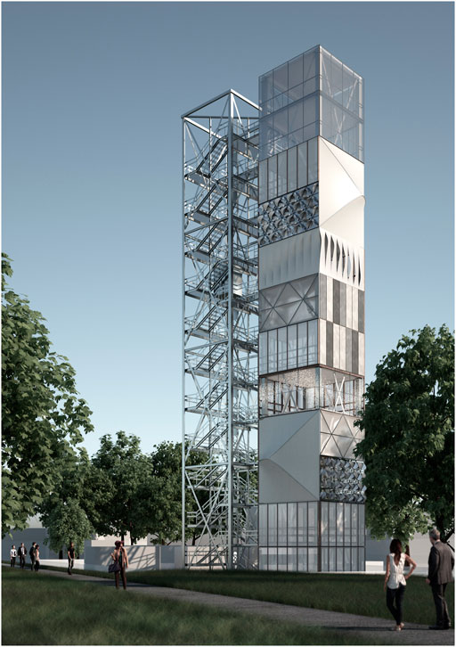
FIGURE 1. Visualization of the experimental building (source: ILEK).
To achieve maximum flexibility, the vertical circulation system and services have been decoupled from the adaptive structural system. Figure 2 shows the adaptive tower (left) and the staircase-tower (right) that houses all supplying pipes, vertical shafts and cables. Such a layout enables significant flexibility in the interior setting as well as simplified retrofitting of technical assets, for example the integration of a lift. Moreover, if needed every component of the adaptive tower can be replaced by newly developed adaptive systems. The two building parts are statically independent from each other, since the connecting bridges end ca. 20 cm before the demonstration tower’s façade. Flaps can decrease the gap for a safe entrance to the rooms.
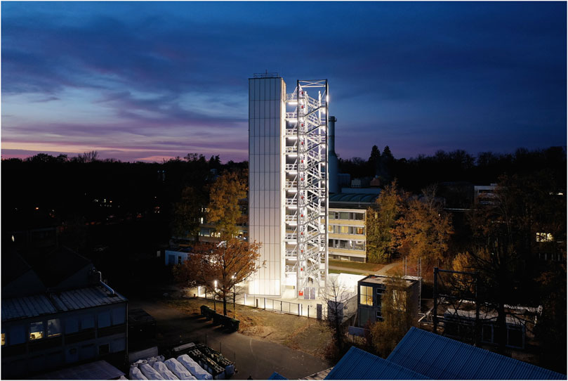
FIGURE 2. Photography of the finalized D1244 in 2021 (source: René Müller).
Essential for the successful design of such a unique and innovative building has been the integration of all stakeholders and disciplines (including mechanical engineers and system dynamics) since the early project stage. While conventional design processes are often architect-centred and linear, the design of D1244 was an iterative, non-linear process where team interaction was of paramount importance (Leistner et al., 2020). In order to reduce the amount of limiting restrictions and laws, the building is not designed for a specific usage (e.g. residential or office). It is meant to serve for research purposes only, thus offering a wide spectrum of possibilities for adaptations and adjustments without the limits of e.g. workplace directives. Yet, for study reasons, test persons can occupy the rooms for a certain test period to simulate a work environment.
The structure has a height of 36.5 m and a width of 5 m. Preliminary investigations have shown that high-rise and slender structures are a promising building typology for the integration of adaptive elements since they are stiffness governed (Steffen et al., 2020). Due to lateral loading (e.g. wind), material input requirement in high-rise structures increases exponentially with gaining height, therefore they offer a great opportunity to improve material resource efficiency. The structural layout is divided into four modules having three stories each. The bracing system consists of diagonal cross bracings positioned on all sides of each module. The width-to-height ratio (i.e. slenderness) is 1:7, which falls within the range of most tall buildings thus making experimental testing relevant and immediately transferable to practical applications.
A variety of different simulation scenarios have been conceived to test the concept of adaptivity in load-bearing structures, thus allowing for an extensive experimental research program. During service, the structure will be controlled to reduce wind-induced vibrations. In addition, vibration control will be performed against solicitations generated by the actuation system. This way the range of loading conditions and the experimental program can be expanded. Generally, the role of the actuators is to redistribute the stress in the structural components with the objective to reduce peak demands under loading. Since the maximum stress can be reduced through this approach, significant saving of material input is enabled by reducing the size of the structural components.
Steel elements allow for a high reliability of sensor measurements; moreover, the wide range of available profile sections enables the integration of both parallel and serial actuation (Weidner et al., 2018). For these reasons, the primary structure of D1244 is made of steel, as this is the ideal material to carry out initial testing on large scale adaptive structural system. Column elements consists of hollow profiles that enable the placing of actuators in parallel: in this case the actuator is installed inside the column profile. On the other hand, actuators are placed in series with the diagonal elements because these are subjected to smaller forces compared to the columns. Section 3 provides further details regarding the actuator installation. The structure is modular: all elements are dismountable; thus, columns, bracing elements, floor slabs as well as facades elements can be replaced. This offers a flexible experimental framework for future research work.
The first adaptive façade elements are currently in the design phase: they will be installed in the top floors of D1244 during the second half of 2022. Every floor will focus on different functions or technologies. The behaviour of switchable insulated glass units will be tested on the 12th floor, following to the extensive research work carried at the ILEK in the past years (Haase et al., 2017). Here the adaptability of the light and energy transmittance of the glazing elements is achieved by means of a liquid crystal technology. After installation the indoor and outdoor conditions will be monitored and evaluated, in order to further develop control strategies and improve performances. Outdoor parameters include solar radiation, temperature, wind speed and relative humidity. Indoor parameters include light intensity, temperature and relative humidity.
An ETFE façade system will be tested on the 11th floor. The lightweight façade elements have several infills that enable control of the appearance, thermal performance and shading capacity of the façade. One of the most promising infills is the Pneumatically Actuated Origami Sun Shading (PAOSS) system that will be installed on the south-west side. Here the lightweight features of textile materials are combined with an integrated active pneumatic system to control light transmission with the objective of reducing room overheating and of increasing user comfort (Eisenbarth et al., 2021). Textile folding structures work well for this purpose thanks to the possibility to deploy from a compact folded to an unfolded state. Moreover, textile fabrics create a unique aesthetic due to their haptic qualities, translucency and texture.
The façade design takes inspiration from the “Starshade” system developed by the NASA (National Aeronautics and Space Administration) (Sigel et al., 2014). The folding technique and the actuation have been further developed in the PAOSS to achieve a robust deployment system, which allows for an effective Sun and glare protection. The unfolding of the element is achieved by means of a central pneumatic actuator, whereas folding is activated by an integrated spiral spring. This way, only a small amount of energy is required for deployment. During the day, the unfolded, opened structure reflects solar radiation, thereby preventing an overheating of the interior. Individually activated single elements enable selective glare protection while at the same time ensuring the required daylight level (Figure 3). Overnight cooling can be also affected to some extent by deployment of the façade elements. The reader is referred to (Eisenbarth et al., 2021) for further details on material selection, folding mechanism, as well as on the actuation technology. The objective of the planned experimental testing is to evaluate the reliability and efficiency of the façade in real weather conditions.
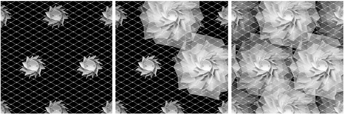
FIGURE 3. PAOSS sun-shading system. In closed state (left), in partially actuated state as selective glare protection (middle) and in open state as full sun protection (right) (source: ILEK/(Eisenbarth et al., 2021)).
A new textile-based hydroactive facade system developed at ILEK will be tested on the 9th and 10th floor. The aim of the so called “HydroSKIN” is to improve rainwater management as well as urban microclimate in the proximity of the building (Eisenbarth et al., 2022). In the 9th floor a conventional unitized glass façade will be optimized by integrating the external “HydroSKIN” add-on elements, thereby showing the retrofitting potential of this technology. The 10th storey represents a further development towards a fully textile and film based, multi-functional hydroactive lightweight façade system. The implementation of the façade systems in the top four floors of D1244 is supported by several manufacturers: Dr. Zwissler Holding AG, Essedea GmbH & Co. KG, Guardian Glass, Merck KGaA, PFEIFER Seil-und Hebetechnik GmbH, RAICO Bautechnik GmbH, Hydro Building Systems Germany GmbH, etc. The remaining facades will host other components whose functions are currently under investigation. Further cooperations are therefore envisioned.
The following sections focus on the structural adaptation, since the research work in this field is in a more advanced stadium.
Adaptive structures require the integration of actuators. Based on the preliminary structural design, a placement concept of the actuators was developed, as explained in detail in the next section. This served as a basis for an iterative optimization process and for the development of the final actuation system.
The objective of the actuator placement algorithm adopted in this work has been to determine which structural elements should be active (i.e. equipped with actuators) to achieve the best possible compensation of stationary disturbances and increase the damping properties using a minimum number of actuators. This is a combinatorial optimization problem based only on control aspects. Due to the large number of structural elements and the resulting high number of possibilities1, finding the optimum by trial and error is not feasible. In this work, the actuator placement has been carried out using an optimization process based on Greedy algorithms: an actuator element is added to each structural element in turn with the objective to maximize a defined quality measure compared to all other possible element locations. For this purpose, two quality measures are defined: 1) compensation of the effect of static loading (e.g. reduction of stress and deflections) (Wagner et al., 2020); 2) increase of damping properties to reduce vibrational motion under dynamic loading (Heidingsfeld et al., 2017). The element utilization ratio can also be included in the quality measure which enables homogenization of the element capacity (Böhm et al., 2019). The static and dynamic structural response is predicted through FE calculations.
Actuator placement should not be carried separately from the sizing of the structural elements, since the structural behaviour depends on the actuator placement. Through actuation, the internal forces are manipulated and therefore element sizing needs to be adapted, resulting in an implicit dependence, which can be solved iteratively. However, it has been shown that a combined (i.e. simultaneous) optimization of actuator placement and structural sizing leads to structures whose static and dynamic response can be controlled effectively. Such structures are lighter compared to passively optimized structures that are actuated in a second step (Geiger et al., 2020). However, the computational cost of simultaneous optimization of structural sizing and actuator placement is high for typical structures. Therefore, an iterative approach was adopted for D1244 to reduce computational efforts: the actuator placement was optimized by the authors as shown in (Heidingsfeld et al., 2017; Wagner et al., 2018; Böhm et al., 2019), whereas optimisation of the structural sizing was carried out by a structural engineering office. At the end of the process, 24 actuators have been placed at specific locations (Figure 4). In this configuration it is possible to adapt to loads coming from all directions since the actuator placement is independent of specific loads or load case assumptions. Depending on the intended experimental test, different set of actuators can be employed to excite as well as to control and damp the structure.
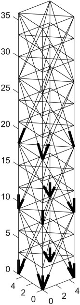
FIGURE 4. D1244 Actuator placement. A bold line at the bottom end indicates an active element. The actuator layout allows for an equally good adaptation for all loading directions (Source: ISYS).
The actuation of a structural element can be done by arranging the actuators in parallel or in series as shown in Figure 5.
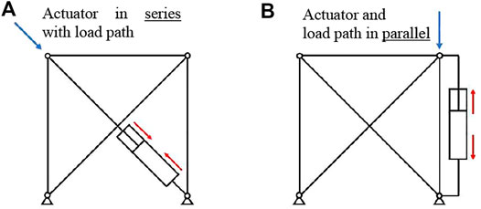
FIGURE 5. Actuation principles: serial (A) and parallel actuation (B) (Source: ISYS/(Böhm et al., 2020)).
Parallel actuation could be more suitable when the element is subjected to high static loads, e.g. due to the structure’s self-weight. In that case, the passive part of the element carries the static load, whereas the effect of dynamic loading is damped through the action of actuators that are installed in parallel. Therefore, control energy is only required to compensate for the dynamic component of the load. In this case, the actuator is connected to the element to be influenced in such a way that the load acts on both. Nevertheless, it must be ensured that the loads can be transferred when the actuator is deactivated. With parallel actuation, the resistance of the hosting structural element must be considered, hence the effect of this type of actuation remains local to the element. On the contrary, with serial actuation there is only resistance from the stiffness of the rest of the structure but none from the hosting element, and thus a larger part of the structure can be controlled through serial actuation (Geiger et al., 2020). As large forces up to 400 kN are needed to actuate D1244 structure, hydraulic cylinders have been employed (Weidner et al., 2018). This limit value is defined as a result of the coordination of the requirements coming from structural and mechanical engineers. Further investigations as to which actuation principle is favourable and in what situation is part of ongoing research within the CRC 1244.
Since the permanent load (self-weight + dead load) is transferred through the columns, actuation has been installed in parallel for the column elements. An active column extends over 3 floors and it includes a passive outer part having a square hollow profile and an active inner part (see Figure 6). The latter comprises a single actuator at the lower end of the column and a smaller hollow profile connecting this actuator with the upper end of the 9 m-column. The inner profile is supported by sliding guides on the outer hollow profile. This prevents buckling under compressive loads. Additionally, relative movement between the inner structure and the hollow profile is possible.
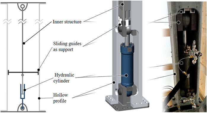
FIGURE 6. Visualization (left) and realization (right) of the column-integrated actuator (Source: IKTD).
A bracing system consists of several components that are articulated to one another and in which the actuators are installed in series (see Figure 7). The active bracing can be prestressed to ensure the stability of the building. The hydraulic cylinder employed in the installation can generate approximately double the compression force compared to the tensile force using the same pressure. For this reason, the cylinder is employed in compression. The compression force is redirected through an auxiliary mechanism to the opposite end of the assembly and into the bracing. This redirection causes the actuator force to act in tension on the bracing. This way, a longer but slimmer actuator assembly could be realized.
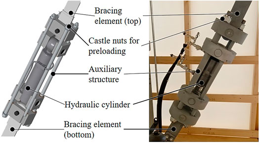
FIGURE 7. Visualization (left) and realization (right) of the bracing-actuator assembly (Source: IKTD).
The stress state of the structure is monitored through strain gauges that are installed on the columns and diagonal bracings. An optical tracking system has been employed to monitor the structure displacements. This consists of infrared emitters placed on two adjacent exterior sides of the building. and connected directly to the supporting structure. The light from the emitters is captured by a camera located on the ground in the vicinity of the building (Guerra et al., 2020). The actuator stroke (change of length) is measured together with the pressure state in each of the cylinder chamber. Additional accelerometers are installed in each module (every three floors) to monitor the dynamic response whereas wind measurement sensors are employed to record the excitation. This way the system state is fully characterized. A battery-buffered acquisition system records all sensor values at a rate of 500 Hz. Based on the acquired data and the mathematical model of the system, anomalies can be detected in order to derive information on sensor and actuator errors (Gienger et al., 2020; Gienger et al., 2021).
The control strategy has two objectives. On the one hand, deformations caused by external loads that exceed serviceability and comfort limitations should be reduced within acceptable limits under all loading scenarios. This can be thought of as adding stiffness when needed since the structure is relatively flexible due to the reduced material input. On the other hand, the actuator system should also reduce the stress and vibrations due to dynamic effects. For this purpose, the structural damping ratio is increased by means of a control algorithm.
Sensors often deliver noisy signals. Furthermore, not all physical effects are considered when modelling the structure motion; this might cause process noise that could lead to significant control inaccuracy. To avoid this, the state predicted from the model simulation is corrected using the measured sensor values. A Kalman filter is employed to minimize the estimation error in the presence of known sensor and process noise. The latter is often not known exactly. However, it can be determined through additional measurements (Warsewa et al., 2020). Strain gauge signals are sampled at 1 ms while displacement measurements are recorded every 10 ms from the optical tracking system. Sensor fusion has been implemented by means of two separate Kalman filter correction steps, where the correction using the optical sensors is performed only every 10th time step. Eventually, the estimated state
Based on the system state estimate
According to (Wagner et al., 2020), the optimization problem can be formulated as follows:
where the inputs are collected in
The optimization problem is solved by an interior-point algorithm as proposed by (Wagner et al., 2020), realized through an implementation of the OPTI Toolbox, a free MATLAB Toolbox for Optimization by Inverse Problems Ltd. from 20142. This method has been successfully validated on a 1:18-scale model (see section 5.1) (Wagner et al., 2020).
An optimal controller is implemented to reduce structural vibrations by increasing the structural damping ratio. Two models are considered. In the first one, it is assumed that the input constraints on u (actuator forces) are not effective and the diagonals can act as tension and compression members, so that the structural model is linear. Therefore, the optimal controller reduces to a linear-quadratic regulator (LQR), for which the feedback law can be analytically derived. The control signals
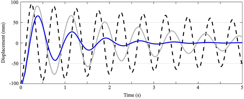
FIGURE 8. Uncontrolled motion of a node at the top of the building (dashed) compared with the controlled motion based on linear (grey) and nonlinear model (blue).
Preliminary testing was carried out on a 1:18-scale model that was built in 2017 (see Figure 9). At that time, D1244 was planned to be made of five modules, each containing two floors. The model is 2 m high and stands on a shaking table that induces vibrational motion in both horizontal directions independently. The model was built in such a way to match the natural frequencies of the full-scale building by installing springs of appropriate stiffness in the diagonals and supports. Using this scaled prototype, the following two algorithms along with the sensor system could be validated in preliminary tests at an early stage: the state estimation using the optical measurements including sensor fusion (Warsewa et al., 2020), and the static compensation by optimization (Wagner et al., 2020) together with feedback damping. The test was not intended to provide information on loadings which are expected in D1244.
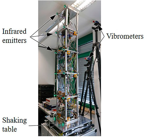
FIGURE 9. 1:18-Scale model. Optical measuring system and two vibrometers to validate the estimated displacement (Source: ISYS).
In order to validate simulation results, a 1:1 scale prototype was built. It has a height of approx. 9 m and a width of 5.2 m (see Figure 10). The structure of D1244 is divided into four modules each containing 3 floors for a total height of 9 m: The prototype reproduces one of the sides of a module at a full-scale: it includes all structural as well as control system components, such as the actuators, strain gauges and the optical measurement system.
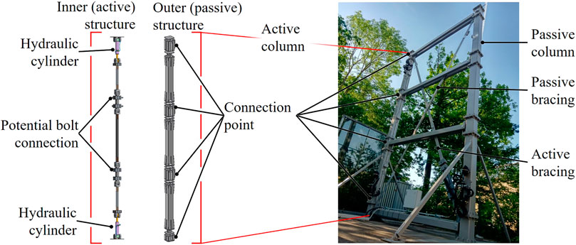
FIGURE 10. Structure of the active column (left) and prototype (right) (Source: IKTD).
The prototype consists of two columns separated by horizontal beams connected via bolts. One of the two diagonal bracings and one column are actuated. In comparison with the final solution for D1244, a slightly different design was implemented for the active column in the 1:1-scale prototype (see Section 3.2). In this case it is also be possible to investigate the influence of the active length of the column. Therefore, the inner (active) structure was developed so that there are two hydraulic cylinders inside the 9 m long column, one at the lower end and one at the upper end, respectively. These cylinders are connected to each other via several elements in a chain-like manner. Sliding guides are used to support the inner elements on the outer hollow profile to prevent buckling of the inner structure. The outer (passive) and inner (active) parts of the adaptive column can be bolted together at each “node” where the horizontal beams are connected to the columns. This prevents relative movement between inner and outer parts at these positions. The load is redirected accordingly. This concept was originally designed to allow for a more flexible experimental setup. However, it was found to be too complex during the design development and therefore was not implemented in D1244. Here there are no optional bolts within an active column, i. e. the active length of an actuated column is fixed.
The bracing function of the diagonals is activated by applying a small pretension force in the elements. The passive diagonal bracing is pretensioned with a turnbuckle, whereas in the active diagonal the pretension is achieved by a length change in the actuator. This is permanently fixed by means of castle nuts on the actuator assembly and secured by splints. Strain gauges are employed to measure the deformation of the structural elements. The sensor values are then used to calculate the element forces, which in active elements corresponds to the force generated by the actuator. Five load cases were tested using the actuator placed on the diagonal by applying forces in the range of 50–200 kN. In addition, a compressive force of -200 kN was tested using the actuators inside the column.
Figure 11 shows a comparison between the stress predicted through the finite element simulations and the strain measurements. The stress in the active column and the passive bracing are observed. The adaptive column is less stiff compared to what was observed through simulation. There are several reasons. For example, the Young modulus assumed in the simulation (210,000 N/mm2) and employed to calculate the stress from the strain measured by the gauges (Weidner et al., 2019) may differ slightly in reality.
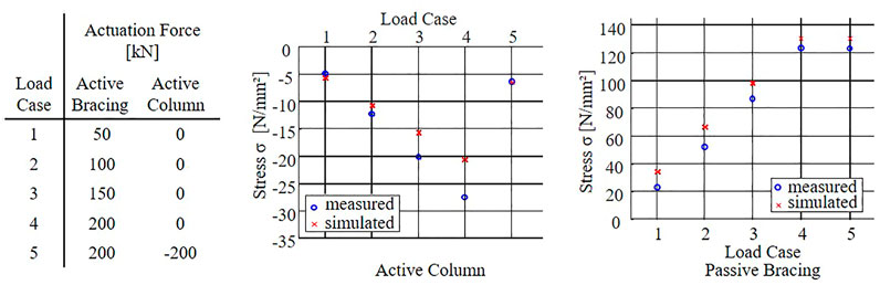
FIGURE 11. Prototype test results (Source: (Weidner et al., 2019)).
In addition, certain simplifications were made in the simulation. For example, the openings within the outer profile, which were necessary to integrate the hydraulic system, were not considered. Moreover, by actuating the bracing element, the column is loaded not only in compression but also slightly in bending. Therefore, the measured values may include additional bending effects, while the simulation foresees only the normal forces. Last but not least, the connections between consecutive column elements are not as rigid as assumed. The constant deviation between the measured and simulated values for the active bracing is due to the fact that the strain gauges were calibrated after installation and application of prestress. Overall, the comparison shows good agreement between the simulation and experimental values. This was the last preparatory step to integrate the tested approaches in the structure of the D1244 at full scale.
The construction of D1244 started in 2020. Figure 12 (left) shows an intermediate stage of construction in February 2021. In order to reduce manufacturing efforts, it was decided to eliminate the possibility of changing the length of the adaptive column, as it was done in the prototype. The option of bolting the outer hollow profile and the inner structure has not been implemented. The typical column, which originally was supposed to span over 6 stories, was therefore divided into two. Both the outer hollow profile and the inner structure of the adaptive column run continuously over three stories with a total length of 9 m. A hydraulic cylinder is located at the lower end of each column and can be accessed for maintenance. Figure 12 (right) shows two bracing- and a column-actuator assemblies at the ground floor.
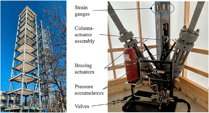
FIGURE 12. left: D1244 during construction phase in February 2021 (Source: ILEK), right: Realization of the actuator systems inside the D1244 (Source: IKTD).
Starting from a central hydraulic unit, oil pipes run to the actuators located in the columns and bracing elements. The hydraulic system operates at a nominal pressure of 260 bar, which can be increased to a maximum of 330 bar: this needs a continuous power of 2 kW for the test operation. A proportional valve is located in front of each hydraulic cylinder, allowing the cylinders to be controlled separately. A high-pressure tank, located adjacent to the cylinder compensates for peak demands. Thus, it is possible to use a hydraulic power unit with a rated output of 15 kW during service. Compared to operations under regular conditions, for example active control of forces and displacement under wind loading, experimental operation requires a higher power because the actuators will also be employed to excite the structure. In addition to the proportional valves, manually operated valves can be used to diagnose failure of individual actuators and subsystems.
A control unit is located inside each module. An additional control unit operates the hydraulic power assembly. The programmable logic controller (PLC) merges sensor values (see section 4.1) measured over the different modules of the structure. Sensor values are transferred via Ethernet interfaces using user datagram protocol (UDP) multicast to the monitoring system. The proportional valves and thus the hydraulic cylinders are controlled via PLC amplifier modules. The control system algorithm has been implemented in Matlab/Simulink. The control hardware communicates via Profinet. Depending on the desired experimental setup, control of the modules can be decentralized or carried out via the central control system.
D1244 is the first adaptive high-rise building in the world (see Figure 13). It is a flexible experimental platform to explore and validate several adaptive systems, most of them developed within Research Centre CRC 1244. Thanks to adaptive structures it is possible to drastically reduce the use of resources, since buildings can react to varying loadings as wind or earthquake by means of sensors, actuators and control units. This is an alternative way to withstand such loads; rather than using structural mass, D1244 utilizes specifically induced countermovements: the conventional sizing of structural element for conditions which occur only on a very irregular basis can be this way overcome and lead to a better ecological footprint of such structures. A similar potential is present in adaptive façade systems: here the target is to reduce resource consumption and energy input, while improving the comfort of users and inhabitants. A resource saving of up to 30% (material) compared to a light-weight passive structure can be achieved (Ostertag et al., 2020). Looking at the greenhouse gas emissions during the whole life-cycle of the building shows that a reduction by more than 40% can be reached. This calculation includes energy related emissions for the adaptive elements.
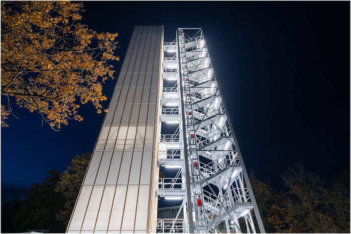
FIGURE 13. View of the completed high-rise building D1244 (Source: René Müller).
D1244 is based on a modular design for the structural and façade components. This allows at a later stage to replace several elements to test different what-if scenarios. This way the building can evolve gradually, while new components developed within the frame of the research group CRC 1244 are being investigated. In general, the design process has been more complex compared to that of a conventional building. This is also due to the fact that the innovative approach implemented and its strong interdisciplinary character has led to further development while the building was being planned. The demonstrator thus works not only as a test platform but also serves to develop methods and processes for the design of adaptive buildings (Leistner et al., 2020).
The development of mock-ups and scale models was crucial, since they allowed for an early assessment on the implemented methods and technologies: this has led to an improved design of the actuation as well as to an optimised electronics installation. The upcoming tests will focus on the performance of each developed component, such as the optical sensors and the actuators, but also on the behaviour of the entire system. Moreover, both centralized and decentralized control strategies will be tested and validated. Failures of individual components, e.g. of actuators and sensors will be specifically triggered in a controlled way in order to analyse the resulting effects.
D1244 will demonstrate how actuation and sensor technology combined with control and monitoring can be integrated in a high-rise building. For the construction of the building, current standards regarding safety and reliability had to be met. In case of failure of the actuators and the control system, the building changes to a passive state. In this state, it is equivalent to a conventional building in terms of safety aspects. If failure and safety concepts are taken into account during the design phase, the structural efficiency will be further increased.
The model-based toolchain supporting simulation, analysis and design of adaptive systems together with the methodologies developed within CRC 1244 has laid the foundation for the design and realization of adaptive building structures. In the future this will expand to other types of structures than just high-rise buildings. In the meantime, the model-based tool-chain is going to be further investigated. Among others the logic of digital twin is going to be further developed. On the one hand, this will allow for an easier integration of additional new components and information on maintenance and disassembly strategies; on the other hand, an integrated monitoring and a more precise evaluation of structural and energetic performances as well as a better life cycle analysis will thus become possible in the near future.
Future component development will focus on façade elements. Different adaptive envelope solutions are being designed to test functions such as dynamic shading and glare control, energy production and storage and to foster interaction with the users. The most promising systems will be implemented in D1244 and validated through an extensive testing and monitoring process. Collaborations have been established with several façade manufacturers to develop and build the adaptive facades of the ground floor and the upper five floors; further collaborations will follow in the coming years. The approach to design structures and facades implemented through this work could potentially lead to new developments in the construction sector within a short-to-medium time frame. The results obtained so far show the potential of adaptive design strategies to lead to a new kind of sustainable architecture that optimally meets human needs.
The raw data supporting the conclusions of this article will be made available by the authors, without undue reservation.
LB organised the paper structure, supervised the contributions and has written the introduction. Design and realisation of D1244 (2.1, 2.2, 5.3): SW. Adaptive facades (2.3) and conclusion: LB and WH. Actuation and related prototype (3 and 5.2): TB, DR and MB. Control and scale model (4 and 5.1): MB. Funding and review: OS, WS, LB. Architectural and structural design of D1244: WS. All authors contributed to the article, reviewed the text and approved the submitted version.
This work is funded by the Deutsche Forschungsgemeinschaft (DFG, German Research Foundation)–Project-ID 279064222–SFB 1244. The authors are grateful for the generous support.
The authors declare that the research was conducted in the absence of any commercial or financial relationships that could be construed as a potential conflict of interest.
All claims expressed in this article are solely those of the authors and do not necessarily represent those of their affiliated organizations, or those of the publisher, the editors and the reviewers. Any product that may be evaluated in this article, or claim that may be made by its manufacturer, is not guaranteed or endorsed by the publisher.
1The structure of D1244 has 48 elements that are potentially suitable for actuation. For example, there are about 6.54 × 10⁹ possibilities to position 10 actuators. With 20 actuators, there are about 2,500 times as many. Eventually, 24 elements were selected
2More information can be found online at https://www.inverseproblem.co.nz/OPTI/index.php/Main/HomePage
Bedon, C., Honfi, D., Machalická, K. V., Eliášová, M., Vokáč, M., Kozłowski, M., et al. (2019). Structural Characterisation of Adaptive Facades in Europe - Part I: Insight on Classification Rules, Performance Metrics and Design Methods. J. Build. Eng. 25, 100721. doi:10.1016/j.jobe.2019.02.013
Bedon, C., Honfi, D., Machalická, K. V., Eliášová, M., Vokáč, M., Kozłowski, M., et al. (2019). Structural Characterisation of Adaptive Facades in Europe - Part II: Validity of Conventional Experimental Testing Methods and Key Issues. J. Build. Eng. 25, 100797. doi:10.1016/j.jobe.2019.100797
Blandini, L. (2021). “Glass Facades: Present and Future Challenges, Ce Papers,” in Engineered Transparency2021. Editors B. Weller, H. Schneider, C. Louter, and S. Tasche (Berlin: Ernst & Sohn), 1–12. doi:10.1002/cepa.1621
Böhm, M., Steffen, S., Gade, J., Geiger, F., Sobek, W., Bischoff, M., et al. (2020). “Input Modeling for Active Structural Elements - Extending the Established FE-Workflow for Modeling of Adaptive Structures,” in IEEE Int. Conf. on Advanced Intelligent Mechatronics (AIM 2020), Boston, MA, USA, 6-9 July 2020.
Böhm, M., Wagner, J., Steffen, S., Sobek, W., and Sawodny, O. (2019). “Homogenizability of Element Utilization in Adaptive Structures,” in IEEE International Conference on Automation Science and Engineering (CASE), Vancouver, BC, Canada, 22-26 Aug. 2019.
Eisenbarth, C., Haase, W., Blandini, L., and Sobek, W. (2022). Potentials of Hydroactive Lightweight Façades for Urban Climate Resilience. Civ. Eng. Des. (in press). doi:10.1002/cend.202200003
Eisenbarth, C., Haase, W., Klett, Y., Blandini, L., and Sobek, W. (2021). PAOSS - Pneumatically Actuated Origami Sun Shading. J. Facade Des. Eng. 9 (1), 147–162. doi:10.7480/jfde2021.1.5535
Geiger, F., Gade, J., von Scheven, M., and Bischoff, M. (2020). “Optimal Design of Adaptive Structures versus Optimal Adaptation of Structural Design,” in Proc. of the 21st IFAC World Congress, Berlin, Germany, July 12-17, 2020.
Gienger, A., Ostertag, A., Böhm, M., Bertsche, B., Sawodny, O., and Tarín, C. (2020). Data-based Distributed Fault Diagnosis for Adaptive Structures Using Convolutional Neural Networks. Un. Sys. 08, 221–228. doi:10.1142/S2301385020500156
Gienger, A., Wagner, J., Bohm, M., Sawodny, O., and Tarin, C. (2021). Robust Fault Diagnosis for Adaptive Structures with Unknown Stochastic Disturbances. IEEE Trans. Contr. Syst. Technol. 29, 1131–1146. doi:10.1109/TCST.2020.2993068
Guerra, F., Haist, T., Warsewa, A., Hartlieb, S., Osten, W., and Tarín, C. (2020). Precise Building Deformation Measurement Using Holographic Multipoint Replication. Appl. Opt. 59 9, 2746–2753. doi:10.1364/ao.385594
Haase, W., Husser, M., and Sobek, W. (2017). “Potential of Structured Switchable Glazing,” in Proceedings of Glass Performance Days, Tampere (FI), 6–211.
Heidingsfeld, M., Rapp, P., Bohm, M., and Sawodny, O. (2017). “Gramian-based Actuator Placement with Spillover Reduction for Active Damping of Adaptive Structures,” in IEEE International Conference on Advanced Intelligent Mechatronics, Munich, Germany, 3-7 July 2017, 904–909. doi:10.1109/AIM.2017.8014133
Leistner, S., Honold, C., Maierhofer, M., Haase, W., Blandini, L., Sobek, W., et al. (2020). Research on Integral Design and Planning Processes for Adaptive Buildings. Archit. Eng. Des. Manag. 16, 1–20. doi:10.1080/17452007.2020.1856031
Loonen, R. C. G. M., Trčka, M., Cóstola, D., and Hensen, J. L. M. (2013). Climate Adaptive Building Shells: State-Of-The-Art and Future Challenges. Renew. Sustain. Energy Rev. 25, 483–493. doi:10.1016/j.rser.2013.04.016
Neuhaeuser, S., Weickgenannt, M., Witte, C., Haase, W., Sawodny, O., and Sobek, W. (2013). Stuttgart SmartShell – A Full Scale Prototype of an Adaptive Shell Structure. J. Int. Assoc. Shell Spatial Struct. 54, 259–270.
Ostertag, A., Schlegl, F., Gienger, A., Wagner, J., Dazer, M., Bertsche, B., et al. (2020). “Reliable Design of Adaptive Load-Bearing Structures with Focus on Sustainability,” in Proceedings of the 30th European Safety and Reliability Conf. and 15th Probabilistic Safety Assessment and Management Conf. ESREL 2020 and PSAM 15, Venedig, June 21–26, 2020. doi:10.3850/978-981-14-8593-0_3806-cd
Reksowardojo, A. P., Senatore, G., and Smith, I. F. C. (2020). Design of Structures that Adapt to Loads through Large Shape Changes. J. Struct. Eng. 146 (5), 04020068. doi:10.1061/(ASCE)ST.1943-541X.0002604
Senatore, G., and Reksowardojo, A. P. (2020). Force and Shape Control Strategies for Minimum Energy Adaptive Structures. Front. Built Environ. 6, 105. doi:10.3389/fbuil.2020.00105
Sigel, D., Trease, B. P., Thomson, M. W., Webb, D. R., Willis, P., and Lisman, P. D. (2014). “Application of Origami in Starshade Spacecraft Blanket Design,” in ASME 2014 Design Engineering Technical Conferences and Computers and Information in Engineering Conference (DETC), Buffalo, New York, USA, August 17–20, 2014.
Sobek, W., Sawodny, O., Bischoff, M., Blandini, L., Böhm, M., Haase, W., et al. (2021). Adaptive Hüllen und Strukturen. Bautechnik 98, 208–221. doi:10.1002/bate.202000107
Sobek, W. (2016). Ultra-Lightweight Construction. Int. J. Space Struct. 31, 74–80. doi:10.1177/0266351116643246
Steffen, S., Weidner, S., Blandini, L., and Sobek, W. (2020). Using Influence Matrices as a Design and Analysis Tool for Adaptive Truss and Beam Structures. Front. Built Environ. 6, 83. doi:10.3389/fbuil.2020.00083
Svetozarevic, B., Begle, M., Jayathissa, P., Caranovic, S., Shepherd, R. F., Nagy, Z., et al. (2019). Dynamic Photovoltaic Building Envelopes for Adaptive Energy and Comfort Management. Nat. Energy 4, 671–682. doi:10.1038/s41560-019-0424-0
UNEP (2020). 2020 Global Status Report for Buildings and Construction: Towards a Zero-Emissions, Efficient and Resilient Buildings and Construction Sector. Nairobi: UNEP.
Wagner, J. L., Gade, J., Heidingsfeld, M., Geiger, F., von Scheven, M., Böhm, M., et al. (2018). On Steady-State Disturbance Compensability for Actuator Placement in Adaptive Structures. A. T. - Autom. 66, 591–603. doi:10.1515/auto-2017-0099
Wagner, J. L., Gienger, A., Stein, C., Arnold, P., Tarín, C., Sawodny, O., et al. (2020). Optimal Static Load Compensation with Fault Tolerance in Nonlinear Adaptive Structures under Input and State Constraints. Front. Built Environ. 6, 93. doi:10.3389/fbuil.2020.00093
Wang, Q., Senatore, G., Jansen, K., Habraken, A., and Teuffel, P. (2021). Seismic Control Performance of a Three‐story Frame Prototype Equipped with Semi‐active Variable Stiffness and Damping Structural Joints. Earthq. Engng Struct. Dyn. 50 (13), 3379–3402. doi:10.1002/eqe.3514
Wang, Y., and Senatore, G. (2020). Minimum Energy Adaptive Structures - All-In-One Problem Formulation. Comput. Struct. 236, 106266. doi:10.1016/j.compstruc.2020.106266
Warsewa, A., Böhm, M., Guerra, F., Wagner, J. L., Haist, T., Tarín, C., et al. (2020). Self-Tuning State Estimation for Adaptive Truss Structures Using Strain Gauges and Camera-Based Position Measurements. Mech. Syst. Signal Process. 143, 106822. doi:10.1016/j.ymssp.2020.106822
Weidner, S., Kelleter, C., Sternberg, P., Haase, W., Geiger, F., Burghardt, T., et al. (2018). The Implementation of Adaptive Elements into an Experimental High-Rise Building. Steel Constr. 11 (2), 109–117. doi:10.1002/stco.201810019
Keywords: adaptive structures, adaptive envelopes, experimental high-rise, interdisciplinary design, sustainability
Citation: Blandini L, Haase W, Weidner S, Böhm M, Burghardt T, Roth D, Sawodny O and Sobek W (2022) D1244: Design and Construction of the First Adaptive High-Rise Experimental Building. Front. Built Environ. 8:814911. doi: 10.3389/fbuil.2022.814911
Received: 14 November 2021; Accepted: 09 May 2022;
Published: 06 June 2022.
Edited by:
Ann Christine Sychterz, University of Illinois at Urbana-Champaign, United StatesReviewed by:
Nizar Bel Hadj Ali, École Nationale d'Ingénieurs de Gabès, TunisiaCopyright © 2022 Blandini, Haase, Weidner, Böhm, Burghardt, Roth, Sawodny and Sobek. This is an open-access article distributed under the terms of the Creative Commons Attribution License (CC BY). The use, distribution or reproduction in other forums is permitted, provided the original author(s) and the copyright owner(s) are credited and that the original publication in this journal is cited, in accordance with accepted academic practice. No use, distribution or reproduction is permitted which does not comply with these terms.
*Correspondence: Lucio Blandini, bHVjaW8uYmxhbmRpbmlAaWxlay51bmktc3R1dHRnYXJ0LmRl
Disclaimer: All claims expressed in this article are solely those of the authors and do not necessarily represent those of their affiliated organizations, or those of the publisher, the editors and the reviewers. Any product that may be evaluated in this article or claim that may be made by its manufacturer is not guaranteed or endorsed by the publisher.
Research integrity at Frontiers
Learn more about the work of our research integrity team to safeguard the quality of each article we publish.